1. Introduction
Transportation is a significant contributor to the emission of CO2, which has been identified as a major cause of global warming [
1]. Researchers and governments worldwide are placing significant importance on reducing dependence on fossil fuels and substituting them with environmentally friendly alternatives [
2,
3]. In 2020, the transport sector was responsible for 24% of the total emissions in the UK [
4]. One effective solution is to replace fossil fuels with electrical energy storage for transportation purposes. For example, the UK plans to end the sale of new petrol, diesel, and hybrid cars by 2035 or earlier, and only EVs will be available for purchase [
1].
EV batteries can be charged at home or at public charging points. These chargers are typically powered by the national electricity grid. The interaction between the charger and the grid is critical and must be carefully managed. Charging an EV battery can take as long as 8 h [
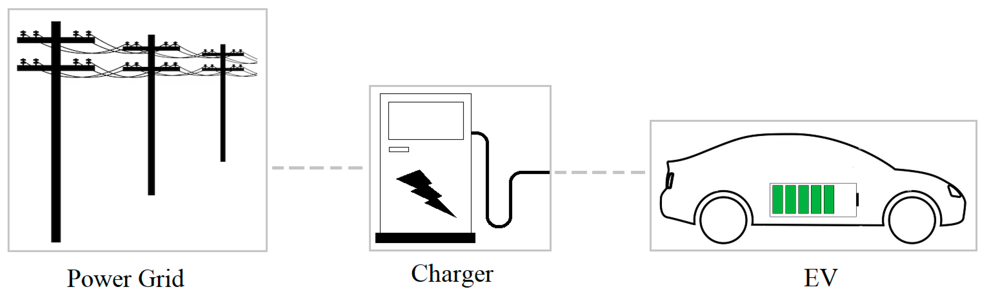
5], the duration of charging depends on the capacity of the battery and the power of the charger being used. As a result, the charger may remain connected to the electrical grid for up to one-third of the day. The overall system is illustrated in
Figure 1. In certain situations, such as when multiple users are utilizing a public charger or when the charger is providing ancillary services to the grid (i.e., supporting the grid by controlling frequency, voltage, and reactive power), the charger may remain connected to the grid for even longer periods of time. Manufacturers of EV chargers believe that the key to widespread adoption of electric vehicles is to create converters that can withstand grid faults [
6]. Grid codes (the technical and operational guidelines and requirements that govern the integration of power generation sources into the electrical grid) [
7] determine the fault ride-through requirements for power electronics-based energy resources, but there are no specific standards for EV battery chargers.
Power network implications of electric vehicles and the various charging standards associated with them are discussed in [
8]. Some researchers are concerned that the interaction between the grid and EVs could limit their widespread adoption, and more research is needed to fully understand of this interaction [
9,
10]. The research community is showing interest in fault ride-through capabilities of Distributed Energy Resources (DERs) due to their continuous growth. EV, while in vehicle-to-grid (V2G) operation mode, is a promising example of DERs.
There is a significant amount of research being conducted on how DERs of various types (even the traditional types) respond to power system disturbances. A review of the literature is presented in this paper on the grid unbalances impact on the EV charger. Since there is a lack of literature related to how EV chargers respond to grid disturbances [
11,
12], the review also includes other applications that have similarities to the battery charging and discharging operations such as PV and energy storage systems (ESS).
The purpose of this paper is to address the importance of comprehending the interaction between EV chargers and the power grid. By gaining a better understanding of this interaction, it becomes possible to develop a resilient EV charger that can effectively manage grid disruptions. To achieve this objective, the research encompasses various aspects associated with the operation of EV chargers. These aspects include investigating how EV chargers respond to grid events, identifying optimal control and fault detection strategies, as well as assessing the influence of charger topology on performance during grid events. As mentioned earlier, there is a limited amount of literature available regarding the response of EV chargers to grid disturbances. The existing literature primarily focuses on investigating the impact of grid unbalances on EV chargers from specific perspectives. This review paper aims to address this gap by providing a comprehensive review that contributes to a better understanding of the topic
There are four major review sections in this paper. Each section considers the impact of grid events on EV chargers from a different perspective. The paper is structured as follows:
Section 2 provides a generic overview that is essential to introduce the topic and its related issues as well as the standards and codes that affect the design and operation of the EV charger.
Section 3 concentrates on how grid events affect EV chargers and explores their responses and behavior in the presence of grid faults. The control side and its related aspects such as fault detection are presented in
Section 4. Control techniques and fault detection strategies are of utmost importance when examining the impact of grid faults on EV chargers.
Section 5 will discuss the impact of the EV charger circuit topologies on its performance during grid unbalances. The performance of an EV charger during grid faults can be influenced by its circuit topology.
Section 6 concludes the paper and discusses the future research.
2. General Review
The ability of DERs to withstand and remain connected to the grid during faulty conditions, known as Fault Ride-Through (FRT) capability, is crucial in preventing unexpected disconnections. FRT capability is determined by the duration in which a DER can maintain its connection to the grid during grid events, which varies depending on the type and intensity of the event.
The main scope of this paper is the impact of grid faults on EV chargers, but it is also important to note that the grid may also be impacted by the charger disconnections due to the abrupt failures of DERs, such as EV battery during V2G operation, can have a detrimental impact on grid operations and potentially result in more severe incidents than the initial fault [
13,
14].
In contrast to traditional synchronous machines that are powered by a mechanical prime mover, which can supply a significant amount of current for a brief period (1~100 ms) and possess high inertia, power electronics-based resources can only supply a slightly higher amount of current than their full load current [
15]. Due to this limitation, it is necessary to conduct further research on the abilities of power electronics-based resources during grid disturbances.
Codes that dictate how to integrate power electronics-based sources specify the necessary FRT capabilities. These requirements determine the duration for which the source must continue supplying energy to the grid during an event, which depends on the type and severity of the event. Two examples of such codes are UK G5/4 and IEEE 1547. G5/4 focuses on limiting the harmonics levels of non-linear equipment connected to the grid as shown in
Table 1, but it does not specify the type and operating conditions of the equipment.
On the other hand, IEEE 1547 provides requirements for interconnecting DERs with the power system. IEEE 1547 addresses universal voltage and frequency FRT requirements for various types of DERs as shown in
Table 2 and
Table 3, respectively. However, neither G5/4 nor IEEE 1547 addresses the response of EV charger to grid faults, and the SAE J2894 standard for plug-in EVs, also doesn’t specify the behaviour of charger during network disturbances [
12,
16,
17]. Several other standards and technical guidelines exist that specifically address the protection of EV chargers against abnormal conditions. These standards primarily emphasize charger protection rather than ride-through capabilities during disturbances [
8,
18].
Table 4 provides a summary of some of these standards. The limited availability of standards and technical guidelines that specifically outline how EV chargers should respond to grid faults can be attributed to many factors. Firstly, the widespread adoption of electric vehicles and EV chargers is a relatively recent topic. Therefore, the industry is still evolving, and codes may take time to catch up with the rapidly advancing technology. Secondly, grid faults and their interaction with EV chargers are complex issues that involve various technical considerations. Developing comprehensive standards and codes that address all possible scenarios and disturbances can be a challenging task. Moreover, power grid systems and their characteristics may vary across different regions and countries. The diverse nature of grid infrastructure makes it a challenge to develop a universal set of standards that can be applied globally.
Based on the grid transient stability, some requirements for the charger are proposed in [
10]. To avoid over currents during voltage sags, it is proposed to consume constant current rather than consuming constant power. It is also suggested that to disconnect the charger from the grid during severe faults and large grid excursions and keep the charger connected during minor faults. However, the author did not define severe faults, large excursions, or minor faults. Furthermore, consuming constant current may affect the charger’s reliability as the charging power will be varied rapidly.
In [
19], practical data was presented on the responses of solar and wind farms to a single-phase to ground fault in a 500 kV transmission system station in Canada. During the fault, dozens of solar and wind farms located at different distances from the fault and connected to different voltage levels of the power system were disconnected from the grid. For example, a 100 MW solar farm at the 230 kV level located 200 km away from the fault disconnected immediately after the fault started and took one second to restart, even though the faulty phase experienced only a 10% voltage sag, and the original fault was cleared within 50 ms. Solar farms at the distribution level of less than 50 kV also disconnected from the grid during the fault, including two 100 MW solar farms connected to a 44 kV distribution grid and located at 70 km and 300 km from the fault. Similar disconnections were reported for wind farms, including a 10 MW and a 6 MW wind farm connected to a 28 kV distribution network located at 70 km and 130 km away from the 230 kV fault, respectively.
Although the author did not provide specific reasons for the disconnections except for the sudden phase angle jump observed in the data which forced the solar farms’ controls to initiate protective action. The solar farms’ owner subsequently reviewed the system control settings to avoid future unnecessary disconnections, indicating that power electronics limitations and country grid code requirements were not the cause of such disconnections. The presented data highlights the need for further investigation into the responses of power electronics-interfaced resources to grid contingencies.
The dynamics of a 2 MW PV system connected to the grid during a grid symmetrical fault (three-phase to ground fault) were studied using MATLAB/Simulink in [
20]. The fault is located 14 km away from the PV system. The study found that the output power of the PV system was significantly affected by the grid fault, and the DC link voltage experienced a 60% overshoot during the fault. The PV system voltage remained in a transient state for 3.5 s even after the fault was cleared. The study also found that the PWM pulses generated by the system were affected by the fault, with changes in the shape, order, and magnitude of the PWM signal indicating the effect of the fault on the inverter controllers. These results provide an indication of what would the EV charger experience during V2G operation as its similarity with the operation of PV system. However, unsymmetrical (unbalanced) faults, where the phase currents, shifts, and voltages are different, could be more challenging to analyse and control.
3. Grid Unbalances Impact on EV Charger
It is acknowledged that EV chargers frequently encounter different grid power quality incidents such as voltage sag, inrush currents, voltage unbalance, earthed faults, and others. For instant, in situations where the grid voltage falls below 80% of the nominal value, it is recommended to employ under voltage protection measures to disconnect the charger from the grid [
21,
22,
23]. This section reviews several research studies that have explored the effects of grid events on the performance of EV chargers.
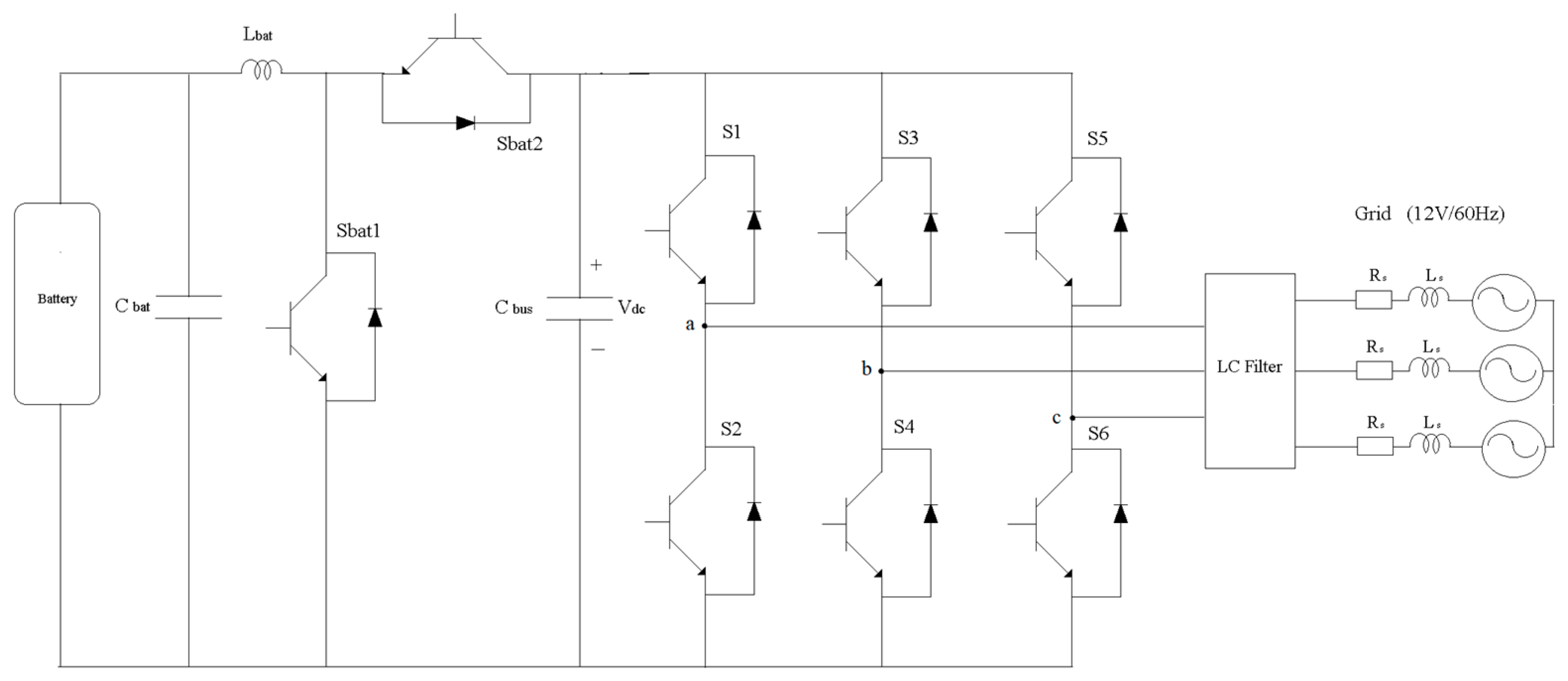
An 8 kW bidirectional EV charger system shown in
Figure 2 is simulated to assess its performance under various scenarios in [
24]. The system is tested and analyzed for cases involving voltage sag, voltage unbalance, and local load variation.
In the G2V (Grid-to-Vehicle) mode, a 15% voltage sag has a negligible impact on the DC bus voltage, allowing the battery to charge normally. However, when the voltage sag increases to 30%, the charger system experiences significant oscillations. The DC voltage oscillates between 0 V and 600 V, leading to distortion of the Point of Common Coupling (PCC) voltage and the propagation of severe current oscillations to the battery. In the V2G (Vehicle-to-Grid) mode, both a 15% voltage sag and a 30% voltage sag do not disrupt the battery current, and the PCC voltage and DC bus voltage remain stable, similar to their operation before the voltage sags occur.
In [
11], twenty-two EV bidirectional chargers are connected to a thirteen-bus grid to examine their response to grid voltage sags due to faults that are applied in two locations within the grid (and three types of faults are used) while in V2G mode. During the grid faults, chargers managed to reduce the grid harmonics with almost the same percentage for both fault locations, but the grid voltage is supported by the chargers with a variation in the level depending on the fault location. The longer the distance from the fault, the higher the improvement in the grid voltage which is achieved by chargers injecting the necessary reactive power to the grid. Furthermore, there is no considerable variation in the level of grid voltage improvement depending on the fault type for the far-fault. But there is a significant variation for the near-fault case as the voltage is improved by 462%, 120%, and 240% (i.e., higher voltage is attained) during line to ground, line to line, and symmetrical faults, respectively. The authors did not mention and discuss such observations. The charger control technique, fault detection method, and G2V operation are also not discussed.
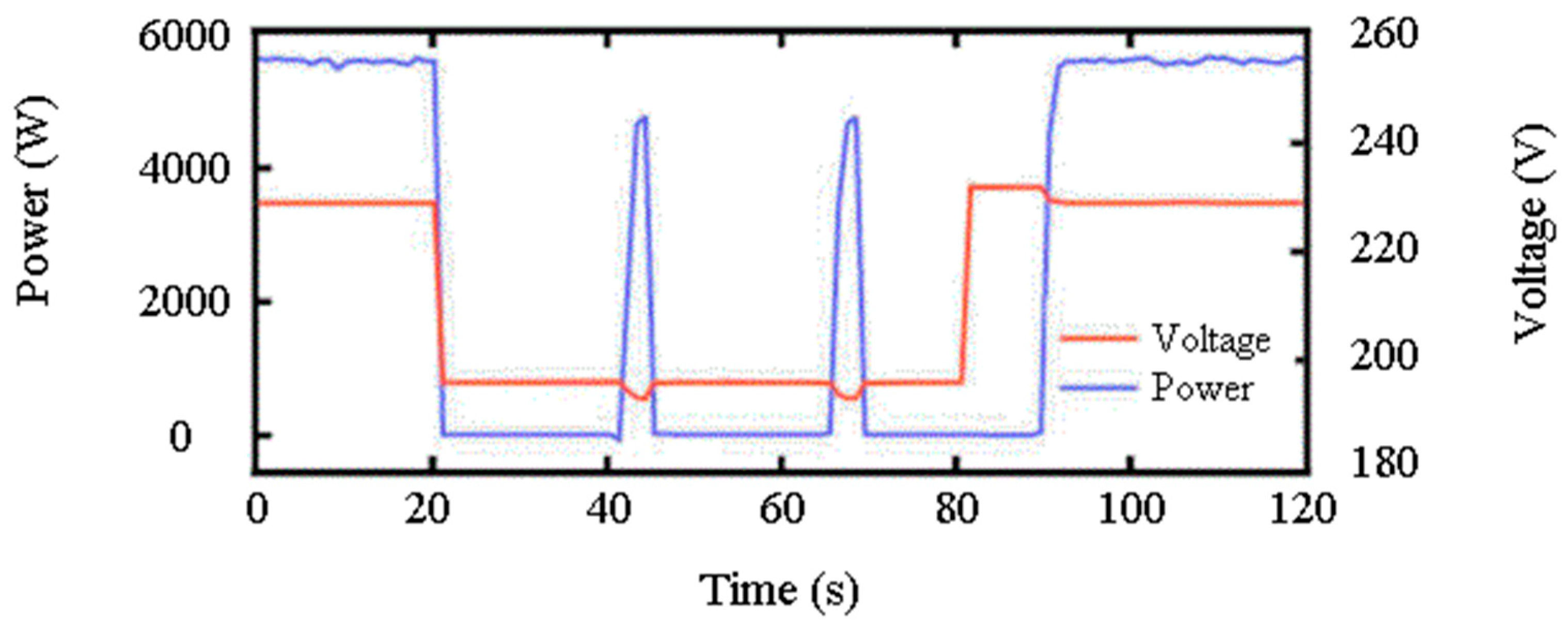
An experiment is conducted to test a wall-mounted practical bidirectional charger in [
25]. A grid simulator is used to test the charger’s ability to handle changes in grid frequency and voltage sags. The results showed that the charger was able to handle a step drop of 2 Hz while charging and discharging, but it failed to handle a step rise of 2 Hz or a +1 Hz/s rate of change in grid frequency while charging. It took almost 20 s for the charger to recover (i.e., return to the pre-fault power level) from a voltage drop from the normal operating voltage of 230 V to 202 V for 60 s. However, when the voltage was reduced to 196 V for 60 s, the charger did not recover and remained disconnected for almost 10 s after the voltage sag was cleared as shown in
Figure 3. The authors did not provide an explanation for this delay in the charger’s re-operation. As shown in
Figure 3, the charger attempts to return to the pre-fault power level every 20 s. On the third attempt, the charger was able to successfully resume operation after the voltage returned to the predefined limits set in the control system.
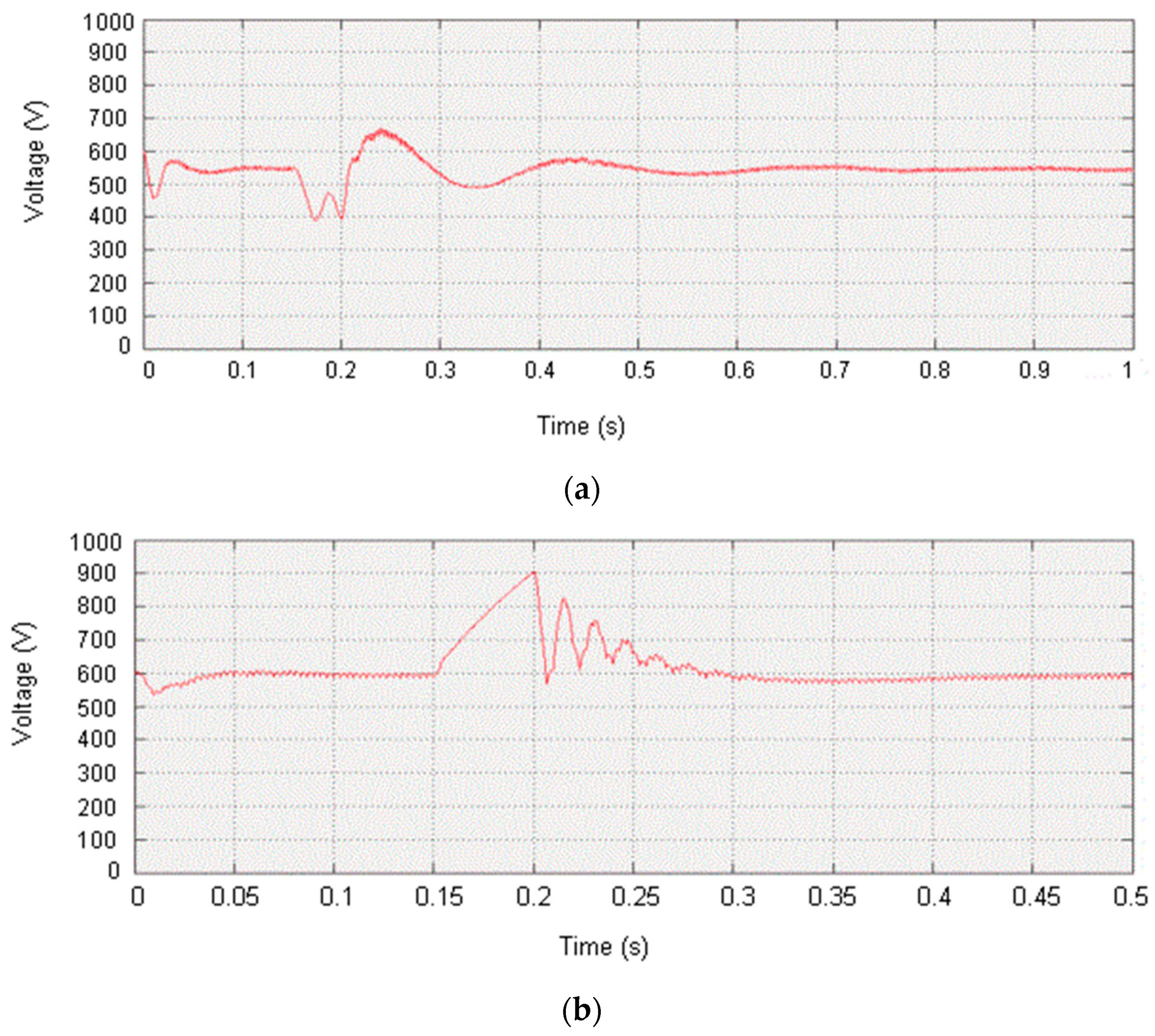
A further insight into the grid unbalance impact on the EV charger in terms of the effect of the EV charger’s working state (charging or discharging) on its response to grid disturbances is provided in [
16]. The study investigates how a bidirectional EV charger responds to grid voltage surge, voltage sag, and network reclosing action during both charging (G2V) and discharging (V2G) operation modes. The results show that when a grid reclosing is applied for 50 ms while the charger is in G2V mode, the charger output voltage and current are stabilized 0.8 s and 0.21 s after the reclosing, respectively. In the case of the charger being in V2G mode, the output voltage is stabilized 0.3 s after the reclosing, and almost no output current fluctuations are observed. A 20% grid voltage sag is also applied for 50 ms. It takes 0.8 s and 0.15 s for the charger to stabilize the output voltage and current, respectively, while in the charging state, and 0.25 s to stabilize the output voltage in the discharging state, with no considerable output current fluctuations. A voltage rise of 20% is applied to the grid for 50 ms, and the charger output voltage is recovered after 0.5 s while in charging mode and 0.25 s while in discharging mode, with negligible change in output current in both modes. The study concludes that grid transients have a greater impact on the EV charger operation when the charger is in G2V (charging) state, and a lighter impact when the charger is in V2G state. However, the study only relies on the stabilization time factor for comparison, while the reported graphs show that the overshoot in the charger output voltage response to grid reclose while in discharging mode is much larger than the overshoot while in charging mode as shown in
Figure 4. Therefore, it is important to consider and evaluate the impact of such overshoots before deciding which operation state has superiority over the other (i.e., longer stabilization time may have less impact than higher overshoots).
The impact of grid voltage sags on various charger topologies is examined in [
26]. The study reveals that the chargers experience significant changes in output voltage in response to variations in input voltage. Furthermore, it is found that three-phase voltage dips have more effect on charger operation compared to two-phase or single-phase voltage dips. The performance of the charger during voltage sag disturbances is influenced by the characteristics of the voltage sag and the charger’s operational state. Additionally, the charger’s response is also influenced by its output power during grid voltage sags, with lower output power resulting in a higher ability to withstand voltage sags.
Section 5 of the paper provides further details on this study.
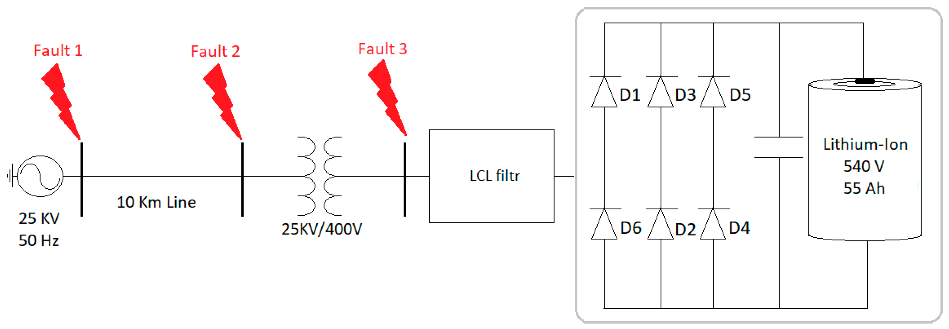
The MATLAB/Simulink simulation environment is used to test a three-phase unidirectional battery charger connected to a 10 km long power line against grid faults in [
27]. A phase-to-phase fault is intentionally triggered at three different locations, as shown in
Figure 5, for a duration of 2 cycles (0.04 s), resulting in voltage variations that affect the charger. Each fault scenario is repeated for different SOC percentages.
Throughout all three faults and SOC cases (20%, 50%, and 80%), notable voltage changes are observed across the charger switches (diodes). In faults 1 and 2, the diodes connected to the faulty phases A and B (diodes 1, 2, 3, and 6) experience voltage variations ranging from +11.7% to −32.6%. In fault 3, these diodes exhibit a voltage change of +4% to −25%. Diodes 4 and 5, which are connected to the healthy phase C, experience the least impact among all simulation cases during fault 3. Additionally, the location of the fault significantly influences the charger’s response. The voltage drops seen by the charger during faults 1 and 2, occurring on the medium voltage side, are approximately 30% lower than the voltage drop caused by fault 3.
In [
8], it is demonstrated that the charger’s performance is significantly impacted during grid voltage dips in the absence of a voltage support strategy to compensate for the charger’s input voltage. Without support for the charger’s input voltage, voltage sags have adverse effects on the charger’s DC output voltage, the battery’s voltage and current, and the SOC of the battery.
4. A Review of Control and Fault Detection Techniques
Control techniques and fault detection strategies are crucial when studying the impact of grid faults on EV chargers. Control techniques play a vital role in ensuring the optimal performance and safety of EV chargers. They are not only regulating the charging process, but also monitoring the charger’s input and output voltages and currents, and maintaining the desired charging parameters. In the event of grid faults, effective control techniques can help detect and ride-through the fault. Fault detection strategies are also essential for identifying and diagnosing grid faults promptly. Fault detection strategies enable the charger system to detect abnormal grid conditions and take appropriate actions. By implementing appropriate control techniques, the charger can adapt and respond to these grid conditions, ensuring proper charging functionality while minimizing any adverse effects on the grid.
In [
28], two current control strategies for voltage source converters (VSC) under unbalanced grid faults are discussed namely power-characteristic-orientated and voltage-support-orientated controls. The power-characteristic-orientated strategy generates VSC control reference current during grid disturbances to achieve a balanced fault current contribution, constant active power output, or constant reactive power. If the converter has a left current margin, both active and reactive currents can be injected simultaneously. However, the choice of control strategy depends on the application and the priorities of the supplied loads. Additionally, a control system that can identify different types of grid faults and operation states to determine the appropriate control strategy for specific cases requires further investigation. However, such an approach may be of interest to EV charger control design if charging the vehicle and providing the ancillary services to the grid are required simultaneously.
In [
29], more than 25 control strategies for grid-connected photovoltaic inverters with low voltage ride-through (LVRT) were compared. The most effective approaches were those that focused on minimizing the voltage unbalance factor and limiting the inverter current to a safe maximum to prevent overcurrent protection from activating. The International Electrotechnical Commission (IEC) defines the Voltage Unbalance Factor (VUF) as the ratio of negative-sequence voltage to positive-sequence voltage, but this definition ignores the phase angle, which is a critical factor in fault analysis [
30].
where
and
are the negative-sequence voltage and the positive-sequence voltage, respectively. Additionally, the authors concluded that such strategies could minimize inverter overcurrent, prevent active power oscillations, improve inverter capacity utilization, and reduce voltage imbalance. However, the comparison did not address other grid disturbances like frequency variations. Furthermore, the study did not examine if they could be achieved concurrently with other requirements like fault detection and the ability to handle grid reclosing actions.
The first step in initiating a control action in response to grid faults is to detect the fault. The traditional method of detecting the voltage sag, for example, is by computing the RMS voltage, which takes at least half a cycle, which may be considered in some cases as a long time to initiate the required control action. A method that uses a Kalman filter to detect voltage sags at the PCC of the DER for LVRT operation is presented in [
31,
32,
33]. Unlike the traditional method of computing the RMS voltage, the Kalman filter method computes the RMS voltage faster, resulting in a quicker control response and settling time. Despite the clear advantages of this approach over the traditional method, the impact of the control system’s complexity on normal operation and its validity in relation to other grid events are not investigated.
The papers [
14,
34,
35] provide statistical evidence of a correlation between the pattern of 2nd, 3rd, 5th, and 7th harmonics and the prediction of voltage sags which is employed to detect voltage sags early (in their development), as these harmonics can transfer through the grid faster than the reduction in voltage magnitude. However, the method does not consider pre-fault grid harmonic conditions, and its validity with different power system types and sizes is not proven. Moreover, it is not proven that these harmonic patterns are only related to voltage sags and cannot be produced by other types of grid events or loads. Additionally, the feasibility of employing a control system with continuous heavy statistical computation requires further investigation.
The vast amount of power quality data generated during the operations of power systems can make analysis challenging. As a result, there is a need for smart tools and methodologies to detect and classify this data. The review of techniques for detecting and classifying grid disturbances in [
36] concluded that the commonly used techniques for detecting grid events are based on wavelet, Laplace (S), Fourier, and Hilbert Huang transforms, while artificial neural networks, support vector machine, genetic algorithm, expert system, and fuzzy logic are commonly used for event classification. However, some of these techniques have their advantages and disadvantages depending on the grid event that needs to be dealt with, but a combination of them—neuro-fuzzy systems, for example—can be used to accomplish the required features. A summary of the computational efficiency of the aforementioned detection techniques for some grid disturbances is illustrated in
Table 5.
One of the approaches introduced in the literature is the power electronics that mimics the response of synchronous machines. In [
37,
38], a grid-connected inverter is presented that mimics the slow response of a synchronous machine to frequency changes. The proposed control system calculates the reference power signal from a single-phase rather than a three-phase. In the event of a voltage sag caused by a line-to-ground fault, the reference power signals for the healthy phases are computed to provide normal operation power, while the reference power signal for the faulty phase is computed to produce less power to avoid overcurrent passing through the faulty phase. This approach may enhance the fault ride-through (FRT) capabilities against line-to-ground faults. However, for EV chargers, the inverter is bidirectional i.e., capable of both DC-AC and AC-DC conversions, which means that further investigation is needed to determine the feasibility of using this approach with the EV charger.
In [
39], a distribution feeder reconfiguration approach is proposed to enhance the reliability of EV chargers. This approach seeks to identify the optimal grid structure that provides the most reliable operation for the charger by connecting and disconnecting various switches among the radial distribution system while respecting grid constraints. However, while this approach may improve the system reliability for a particular charger or a particular part of the grid, it may also negatively affect the operation of other distributed energy resources (DERs) and loads elsewhere in the grid, as the power flow is altered. In addition, the frequent reconfiguration of complex grid structures requires significant computational effort, and a high number of communications between the charger and grid switches/circuit breakers are necessary.
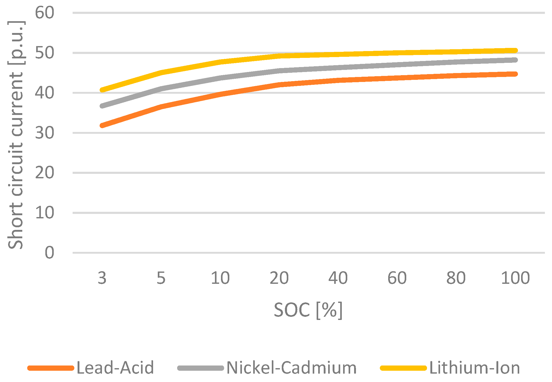
The use of a battery storage system for reducing the short circuit current during grid faults, with and without the use of constant voltage charging control is examined in [
40,
41]. The study uses a 1MW, 3-phase battery storage system with different types of batteries (Lithium-Ion, Nickel-Cadmium, and Lead-Acid) connected to the grid via a bidirectional charger. The results show that the short circuit current produced by line-to-ground and line-to-line faults in the grid is reduced by up to 50% when constant voltage control is used. It also concluded that short circuit current increases with an increase in SOC percentage. As shown in
Figure 6, the rate of increase in short circuit current is particularly high when SOC is between 0% and 50%, and it becomes lower after 50%. Although the author did not provide an explanation for this behaviour, one possible reason is that the internal resistance of the battery decreases as the SOC increases. However, the rate of this decrease slows down as the SOC increases, therefore short circuit current also increases slowly after 50% SOC [
42]. Additionally, the study finds that Lithium-Ion batteries have the highest short circuit current, followed by Nickel-Cadmium and then Lead-Acid batteries, with a difference of approximately 6% between them.
A Sliding Mode Control (SMC)—DC-link voltage controller (SMC-DLVC) that aims to mitigate excessive dc-link voltage overshoot during grid disturbances in all operation modes of an EV charger is introduced in [
43]. The effectiveness of the proposed control algorithm is verified using a laboratory prototype of a 12.6-kVA off-board charger. Although the tests are conducted for a specific type of grid disturbance, namely load variations, the SMC-DLVC control outperforms the conventional proportional-integral DC-link voltage controller (PI-DLVC). The main differences between these two control strategies are summarized in
Table 6.
In [
44], the implementation of model predictive control (MPC) for multiphase EV-drive train on-board battery chargers (OBC) is outlined. The simulations conducted demonstrate the feasibility of supplying a three-phase grid with balanced currents and zero torque from the machine side, both during normal operation and after a fault occurs, using the proposed control scheme. The outer loop of the control strategy is executed at each sampling time, while the inner loop is performed for each possible state. However, the presented results do not indicate the sampling time, which is important to determine if it is suitable for achieving the minimum required fault detection time necessary to trigger the control action.
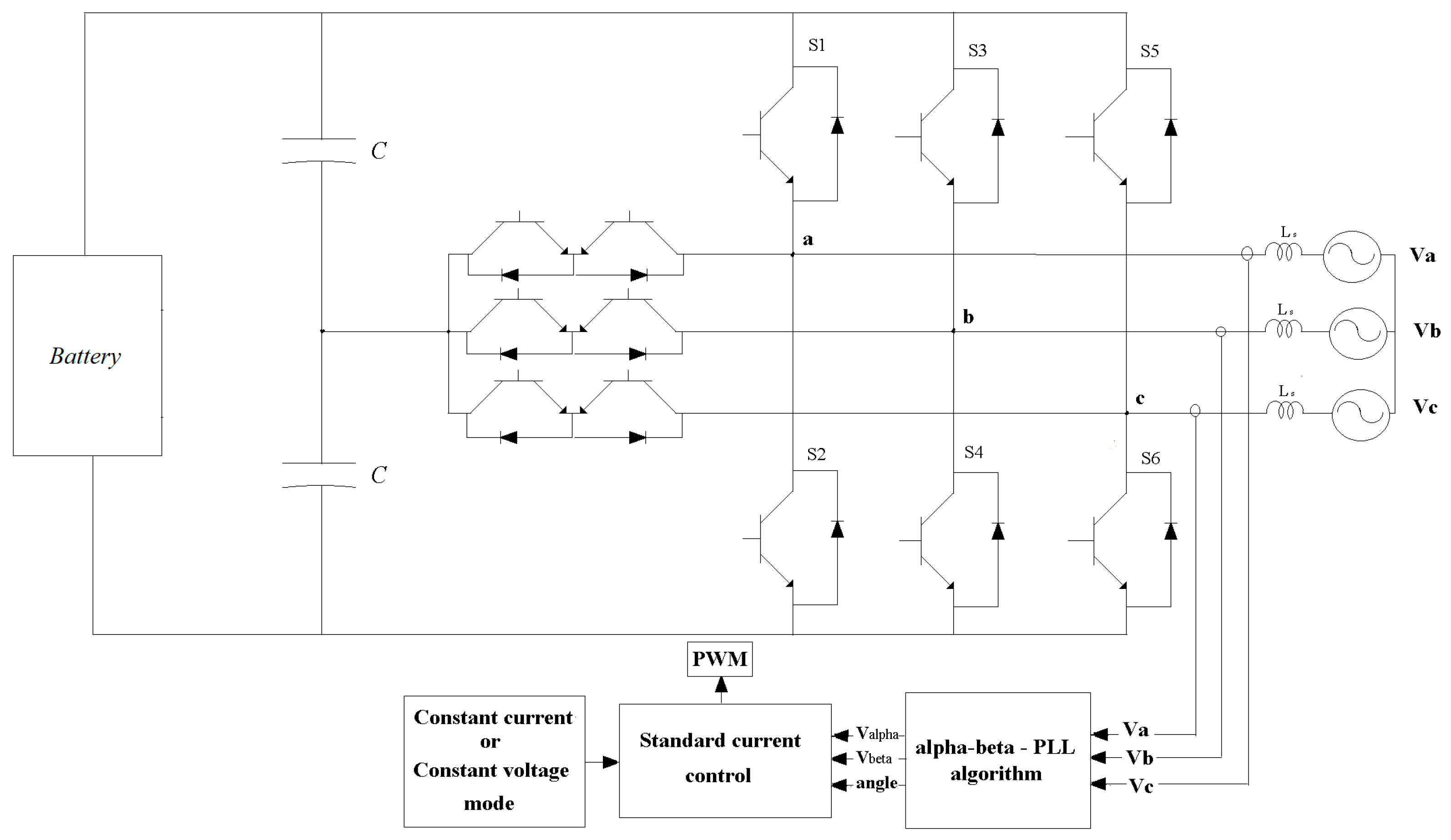
A three-level T-type converter and a proposed control strategy for off-board battery chargers is presented in [
45]. The proposed control strategy aims to generate three-phase sinusoidal currents even in the presence of grid voltage distortions and unbalances. Since the linear grid angle cannot be detected due to abnormal grid voltage, achieving sinusoidal grid currents becomes challenging. To address this, the paper introduces an αβ—Phase Locked Loop (PLL) algorithm derived from the conventional αβ—PLL algorithms. This algorithm utilizes the αβ-axes reference voltage and compares it with the feedback signals to identify any errors. The resulting error is then fed into a PI controller to determine the control angle. The proposed charger is shown in
Figure 7.
When considering faults tolerance, each charger topology has its own advantages and disadvantages. While some topologies may offer benefits in terms of efficiency or component count, they may have drawbacks related to fault ride-through, making them unsuitable for fault-tolerant chargers. However, control strategies can be used to address these drawbacks and enable the use of certain topologies in designing fault-tolerant chargers. For instance, a solution for the problem of unequal power exchange between the grid and a modular multilevel converter (MMC) chain-links during voltage unbalance is suggested in [
46]. The proposed solution involves injecting triple harmonics current into the chain links in proportion to the degree of voltage unbalance.
In [
6], an online optimization of a proportional-integral (PI) controller for coping with faulty semiconductor switches in Vienna rectifiers used for EV charging is presented. The proposed approach optimizes the PI control based on the variations of the output voltage caused by open-switch or short-switch faults. As grid disturbances may cause stress on the charger components, which could result in faulty switch devices, this approach may enhance the fault ride-through capabilities of the EV charger, improving its reliability during grid faults.
5. Circuit Topology Review
The impact of grid disturbances on EV chargers depends on various factors, one of the most important factors is the charger topology. Therefore, selecting the appropriate circuit topology is essential for EV chargers.
In [
26], uncontrolled 6 pulse and 12 pulse rectifiers, as well as pulse width modulator (PWM) rectifier chargers, are tested against grid voltage sags. The study concludes that the output voltage of the 6 and 12 pulse uncontrolled rectifiers changes proportionally to the input voltage changes, while the output voltage of the PWM rectifier reduces rapidly with input voltage dip. The study also finds that 6 and 12 pulse rectifiers perform better than PWM rectifiers during strong voltage sags, although the definition of strong voltage sag is not provided by the author. Additionally, the study concludes that three-phase voltage dips have a stronger impact on charger operation than two-phase or single-phase voltage dips. The characteristics of the voltage sag and the charger’s working state also affect the charger’s performance during voltage sag disturbances. Both 12 pulse and PWM rectifiers are affected by phase jumps due to grid disturbances, but 6-pulse rectifiers are more significantly affected. The charger’s output power during grid voltage sags also influences the charger’s response, with smaller output power resulting in a higher ability to ride through voltage sags.
In [
47,
48,
49], the redundancy and FRT capabilities of the MMC are discussed. Bypassing the damaged switching device due a grid event can enhance the FRT capabilities, but the issue of unequal power exchange between the grid and the MMC chain links which may occur during grid unbalances must be considered, the trade-off between the features of MMC and its control complexity should be carefully evaluated.
A transformer-less, on-board EV charger has been suggested in [
50]. The paper proposes adding capacitors between the charger and the grid to bypass the leakage currents (which are supposed to be blocked by the transformer). However, since the transformer also helps with the voltage conversion, an additional power conversion stage may be necessary for the proposed charger.
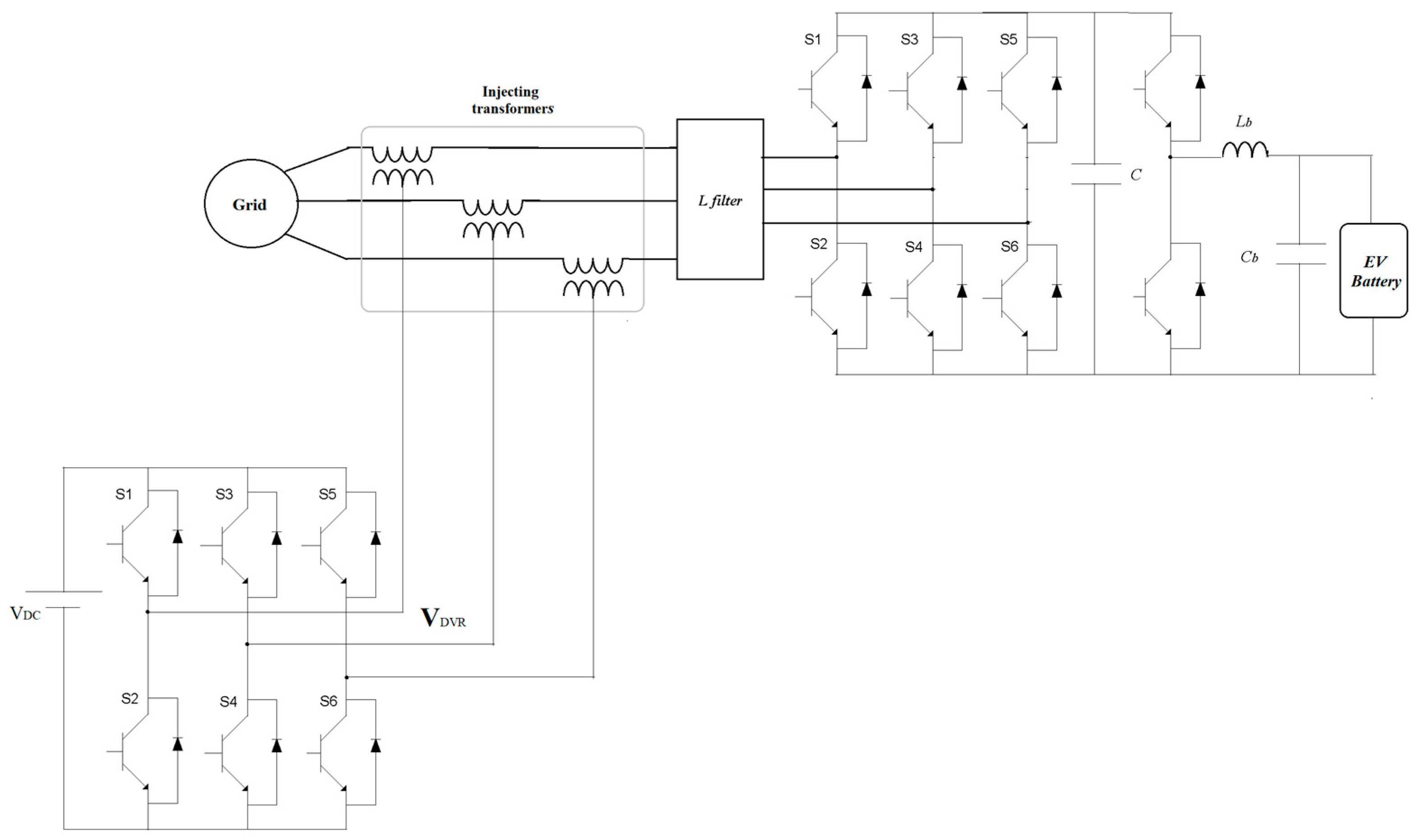
A Dynamic Voltage Restorer (DVR) is a device used to compensate for voltage sags for a short duration at the load PCC. In addition to necessary detection and control mechanisms, the DVR mainly consists of a DC power source (batteries or capacitors), an inverter, and a transformer. The DC power is converted to AC by the inverter and then injected through the transformer, which is connected in series with the feeder and the load.
In [
12], a dynamic voltage restorer (DVR) is used to assist the EV charger’s AC input voltage when there are dips in the grid voltage. The circuit diagram is shown in
Figure 8. Without the DVR, voltage sags have negative effects on the charger’s DC output voltage, the battery’s voltage and current, and its SOC. However, with the DVR in operation, the charger was able to smoothly ride through voltage sags of 30%, 60%, and 90%, without any negative impact on the battery characteristics. However, the DVR has its limitations, as it can only support the load voltage for a limited time and voltage amplitude. Therefore, for longer voltage disturbances, further investigations are required to determine the capacity of the DVR and the depth of the voltage sag it can handle. Additionally, the impact of the DVR transformer on the charger’s performance during various grid disturbances needs to be studied.
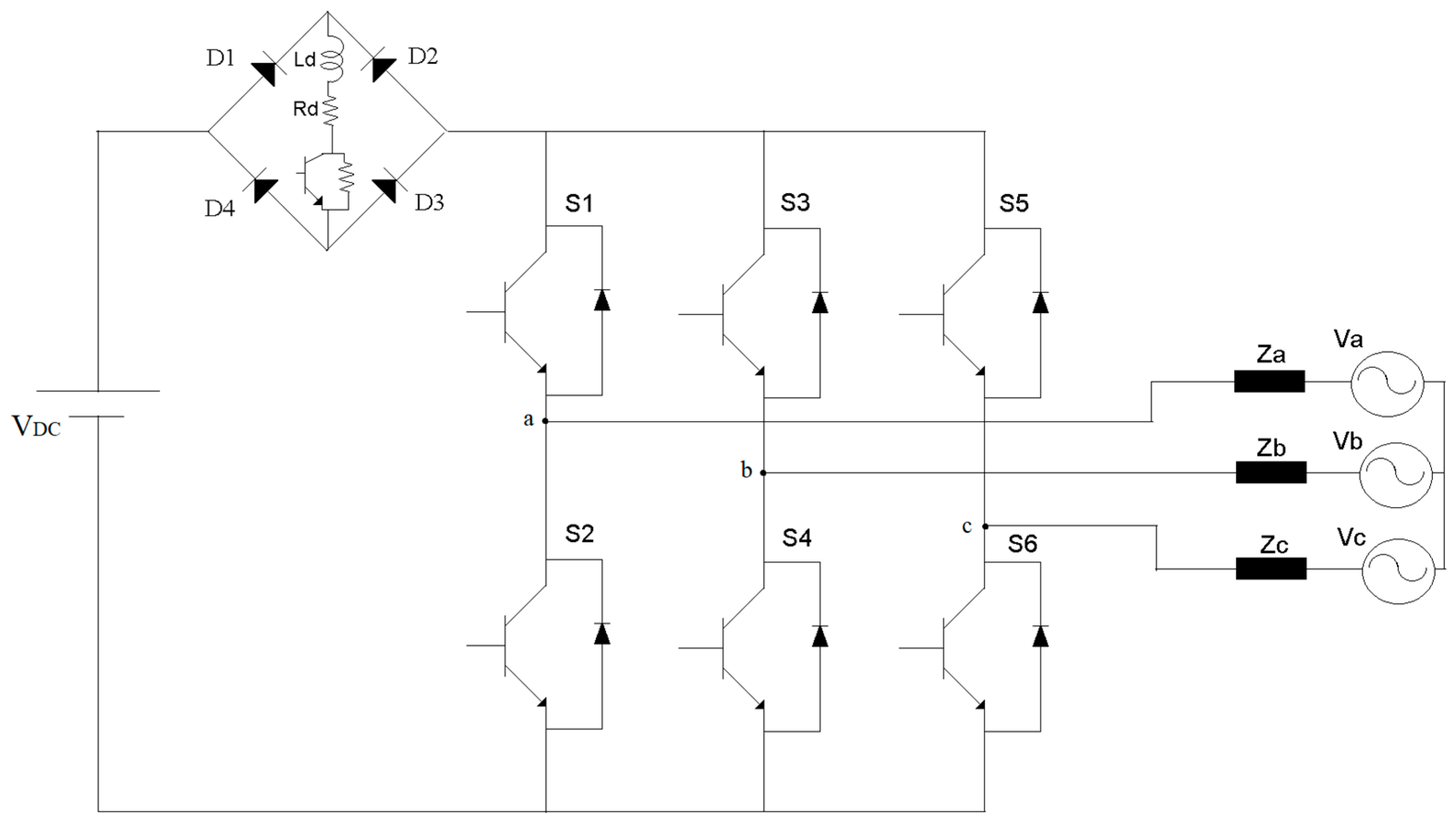
Usually, fault current limiters are connected in series with each phase on the AC side of the inverter, in [
51] a different approach is proposed by connecting a single fault current limiter in series with the inverter on the DC side in order to limit current during grid faults. The proposed limiter is made up of four diodes, an inductor, and a controllable semiconductor switch as shown in
Figure 9. During normal operation, the switch is conducting, and the resistor is bypassed. When the current reaches a predetermined value, the switch turns off and the resistor is connected in series to the inductor to discharge its energy. This effectively limits fault current during three-phase to ground faults. The switch then turns on again according to predefined settings. The proposed limiter sets the maximum inverter current magnitude at 2 p.u. However, the maximum time that the limiter can handle high current is not specified, and the impact of the transients generated by the reactor on charger performance has not been investigated.
In [
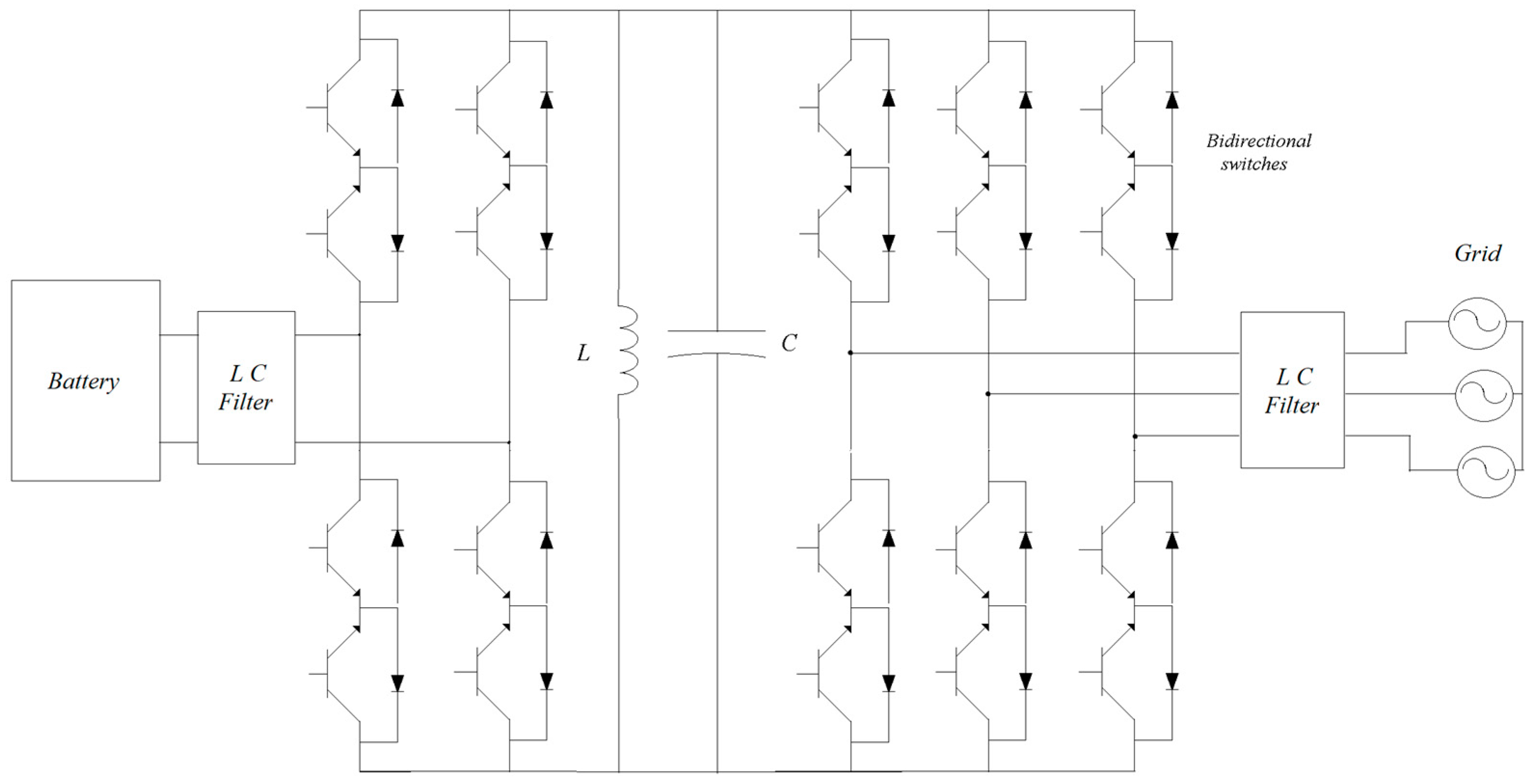
52], the integration of a bidirectional battery storage system with LVRT capabilities into the electrical grid is discussed. A parallel link consisting of a capacitor and an inductor is connected at the DC output (between the inverter and the buck/boost converter) as shown in
Figure 10. During normal vehicle-to-grid operation, the input DC from battery charges the DC-link capacitor to the required level by controlling the bidirectional switches as shown in
Figure 8, and when the switches’ states are changed, the DC-link is discharged to the output side (i.e., the power flows through the link). During the voltage sag, all the switches are turned on and off so that the link is charged with the maximum current, and then it is discharged into the output to compensate for the voltage reduction and maintain the control current references. However, the research does not investigate the duration of the proposed ride-through or the impact of the capacitor charge/discharge dynamics. In [
40], the contribution of a 3-phase, 1 MW battery storage system to short circuit current is discussed when connected to the grid using chargers with different switching devices. The study uses insulated gate bipolar transistor (IGBT)-based and thyristor-based chargers with typical specifications. During the same fault, the thyristor-based charger experienced slightly higher (almost 5%) short circuit current. However, the author did not include the switches’ specifications and details. A summary of the discussed topologies is shown in
Table 7.


