Article

A Scalable Segmented-Based PEM Fuel Cell Hybrid Power System Model and Its Simulation Applications

1
School of Automation and Electrical Engineering, Zhejiang University of Science and Technology, Hangzhou 310023, China
2
Key Institute of Robotics Industry of Zhejiang Province, Hangzhou 310023, China
3
College of Automation Engineering, Nanjing University of Aeronautics and Astronautics, Nanjing 211100, China
4
State Key Laboratory of Fluid Power & Mechatronic System, School of Mechanical Engineering, Zhejiang University, Hangzhou 310058, China
5
Jinhua HydroT Technology Co., Ltd., Jinhua 321017, China
6
Vehicle Measurement Control and Safety Key Laboratory of Sichuan Province, Xihua University, Chengdu 610039, China
*
Author to whom correspondence should be addressed.
Energies 2023, 16(17), 6224; https://doi.org/10.3390/en16176224
Submission received: 8 August 2023 / Revised: 22 August 2023 / Accepted: 25 August 2023 / Published: 27 August 2023
(This article belongs to the Special Issue Advanced Management Techniques for Energy Storage Systems)

Abstract

:
A scalable segmented-based proton-exchange membrane fuel cell (PEMFC) hybrid power system model is developed in this paper. The fuel cell (FC) is developed as a dynamic lumped parameter model to predict the current distributions during dynamic load scenarios. The fuel cell is segmented into 3 × 3 segments connected with several physical ports and with the variables balanced automatically. Based on the proposed model, a real-time energy management framework is designed to distribute the load current demand during dynamic operations. Simulation results show that the proposed strategy has good performance on both single/segmented fuel cell–battery hybrid systems and the low battery state of charge (SOC) situation. This paper proposes an approach that uses an interconnected ordinary differential equations (ODEs) system model in control problems, which makes the control algorithms readily applicable.

1. Introduction

PEMFCs are considered as clean and energy-efficient sources amid the increasing awareness of environmental pollution and the growing energy crisis [1,2]. However, because the fuel cell is a complicated system and has various couplings among its multiple-domain physical subsystems, there are still many research problems that impede its wider applications [3,4]. For example, although fuel cells have great advantages in life and energy conversion during stable operation, their dynamic performance has difficulty meeting the transient peak power demand in high-power application scenarios, which may even affect its lifetime [5]. At the same time, fuel cells cannot be reverse-charged compared to batteries or ultracapacitors. Therefore, with a battery or an ultracapacitor, a fuel cell hybrid power system is produced to enhance the peak power capacity, improve the dynamic output characteristics, and increase the fuel economy [6]. The service life of the whole system is mainly influenced by the fuel cell due to its high manufacturing cost.
A fuel cell–lithium batteries hybrid power system is considered an important form of fuel cell commercial applications [7,8]. Since the current of the fuel cell cannot be mutated and the voltage decreases greatly with the rapid increasing current, the fuel cell is usually connected to a unidirectional DC-DC converter, and then linked to the load. Compared to two DC-DC hybrid power systems, one DC-DC system is simpler and has a lower system cost but with less flexibility [2]. Therefore, a hybrid power system model with one DC-DC converter is proposed in this paper. Many researchers have studied single DC-DC converter hybrid power system models [9,10]. L. M. Fernandez et al. [11] proposed a hybrid electric power system composed of a fuel cell and rechargeable Ni-MH battery for a real surface tramway. K. Simmons et al. [12] established a model of a FC–battery hybrid power system for electric buses. However, researchers always focus on the dynamics of the electrical subsystem of the PEMFC, ignoring the multiphysical coupling between all the subsystems. At the same time, the distributions of key variables are always ignored but are also important in system analysis and life estimation. Thus, producing a fuel cell model considering the multiphysical coupling and the key variables’ distributions is of great importance for the modeling of hybrid power systems.
To distribute the power between fuel cell and battery according to different operating states, control strategies are designed, which are always named energy management strategies (EMSs) [13]. For economic aspects, the EMS always keeps the fuel cells working in a stable range, which extends the lifetime as well as reduces the cost of stack replacement. Many researchers have proposed EMSs based on hybrid power systems with different control objectives [14,15,16]. Considering both fuel economy and system durability, Z. Hu et al. [1] proposed a multiobjective optimization strategy. The output current of the fuel cell system maintained a stable level. L. Xu et al. [10] developed a multiobjective optimization strategy based on the power train parameters for a predefined driving cycle. To minimize fuel consumption, M. Kandidayeni et al. [17] proposed a systemic management strategy that capitalized on both current and thermal control. J. Chen et al. [18] developed an adaptive control approach with fuzzy logic parameter tuning to manage the power. The proposed approach was able to distribute the power timely without predicting the system’s behavior. Y. Yan et al. [19] designed a hierarchical control method that could provide the optimal power distribution under different operating conditions. However, for controller design purposes, most papers have developed EMSs based on lumped-parameter fuel cell models [20,21], which always ignore the distributions for simplicity.
Therefore, for both controller design and system analysis demands, a scalable fuel cell–battery hybrid power system model was constructed based on previous work [4]. The DC-DC converter, battery, and electronic load models were also developed utilizing physical modeling concepts. A real-time power allocation strategy was designed to distribute the power between the fuel cell and the battery during dynamic operations. In addition, simulations of a single-fuel-cell hybrid system and one with 3 × 3 segments were developed to adjust the system’s segmentation scalability. The fuel-cell-only system with 3 × 3 segments was simulated as a comparison to study the current and temperature uniformity. This paper provides an approach that replaces the distributed parameter model with the interconnected lumped parameter model for control design, and the lumped ones can be scaled up and scaled down for different system analysis accuracy demands.
This paper is organized as follows. Section 2 presents the scalable fuel cell–battery hybrid power system model. Section 3 gives the real-time power allocation strategy. A simulation analysis and discussion are provided in Section 4. A conclusion is given in Section 5.

2. Model Description

The system structure is shown in Figure 1. The fuel cell is linked to a DC-DC converter and then to the load, while the battery is directly connected to the load. The fuel cell system contains electrical, thermal, and pneumatic subsystems.
In this model, the fuel cell, battery, DC-DC converter, and load are connected through several physical ports. According to the electrical principle, in a fuel cell stack/battery pack, single cells/batteries are connected in series circuits. The output current of the whole stack/battery pack equals that of a single cell/battery, while the output voltage of the former is N (the number of cells/batteries) times that of the latter. In addition, the capacity of a single battery ( A h ) can be considered equal to the total capacity of the battery pack. To form a battery pack, single batteries might be linked in series, parallel, or mixed, so the capacity ratio of the pack and single one is related to its structure. Thus, single fuel cell/battery models were developed instead of the stack/pack for a better comparison with the segmented fuel cell–battery model.

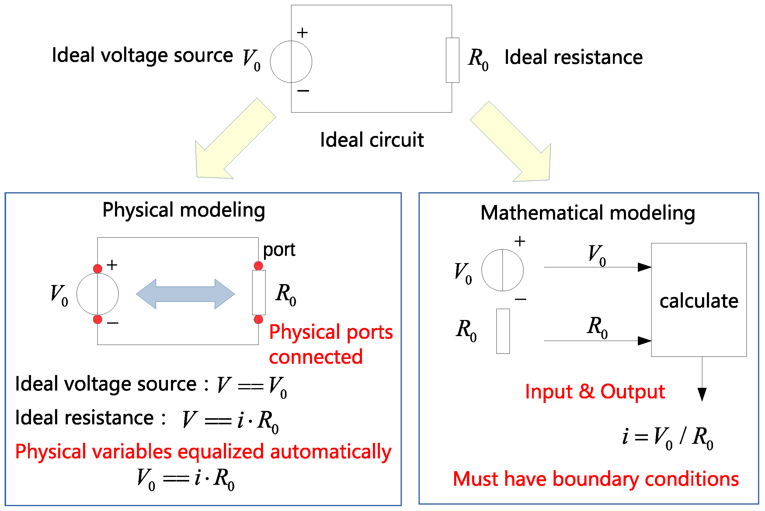
2.1. Physical Modeling Concept

For both controller design and system analysis purposes, the physical modeling concept is applied. For a better understanding, an example is introduced, as shown in Figure 2. In this circuit application, the physical modeling focuses on the principle of the components. When they are linked together with physical ports, the variables are equalized automatically without a lot of boundary conditions. On the other hand, mathematical modeling focuses on the inputs and outputs, which may cause problems when the system needs to be scaled up.
Besides the electrical domain, the system contains gas and thermal domains as well. Additionally, variables belonging to one domain are not only related to the variables in the same domain but have a coupling with the variables in different domains. According to the concept of physical modeling, with the ports connected, variables such as current, voltage, gas flow rate, and temperature can be equalized automatically. There is no need to set a large number of boundary conditions. The proposed model is highly scalable/reconfigurable, which means that the segmentation and structure of the system can be easily rearranged.

2.2. Fuel Cell Model

The fuel cell system model contains the electrical, gas flow, thermal, two-phase water flow, and orifices submodels, which were introduced in previous work [4]; only the main equations are listed to show the multidomain physical coupling of the system.
The electrical submodel is expressed following [22]. The output voltage is influenced by the hydrogen pressure, oxygen pressure, temperature, and current.
V f c = E N e r n s t V a c t V o h m i c V c o n
where V f c is the output voltage; E N e r n s t is the Nernst voltage; V a c t , V o h m i c , and V c o n are the activation, ohmic, and concentration losses, respectively. In particular, V a c t and V c o n are revised as their inverse number according to [23].
The thermal submodel was developed based on thermodynamic principles, which was introduced in previous work [3]. In this model, the temperature is influenced mainly by the current and the coolant water flow rate.
T ˙ f c = f ( T f c , i f c , θ a , θ c ) + g ( T f c , n ˙ w a t e r )
where T f c is the temperature, i f c is the current, θ a and θ c are unknown parameters related to the gas flow rates and gas specific heat capacity in the anode and cathode, and n ˙ w a t e r is the coolant water flow rate.
The gas flow submodel was developed based on hydrodynamics. The gas flows as mixed gases in the flow channels through the orifices [24].
n ˙ m i x · M m i x = A o r · φ · p m i x · C d 2 R / M m i x · T
where n ˙ m i x , M m i x , and p m i x are the molar flow rate, the average molar mass, and the pressure of the mixed gases; A o r is the area of the orifice; the flow function φ and discharge coefficient C d can be calculated following [24]; T is the flow channel temperature and R is the gaseous constant.
The pressure dynamics of hydrogen in the anode are expressed as a representative example, and the pressure dynamics of other gases are developed following the same ideal gas principle.
p ˙ H 2 , a V a = R T ( n ˙ H 2 , a i n n ˙ H 2 , a o u t n ˙ H 2 , a r e a c t n ˙ H 2 , P e r 2 n ˙ O 2 , P e r )
where n ˙ H 2 , p e r and n ˙ O 2 , p e r are the permeation gases, n ˙ H 2 , a r e a c t and n ˙ O 2 , c r e a c t are the reactions gases, which are determined by the output current.
Because in the fuel cells hydrogen reacts with oxygen and produces water, and steam as well as liquid water flow with the mixed gases, the two-phase water flow in the fuel cell is influenced by the gas flow, current, and saturated vapor pressure related to the temperature.
For the hybrid power system simulation, we mainly focused on the output current and voltage, but temperature and gas flow dynamics should also be within appropriate ranges.

2.3. Battery Model

The battery model was developed based on the basic battery module [25] in Simscape with the physical port reconstruction. The battery model contains a controlled voltage source and a resistance. In discharge mode, i * > 0 , while in charge mode, i * < 0 , as follows:
E b a t t e r y d i s c h a r g e = f 1 ( i t , i * , i b a t t e r y ) = E 0 K · Q Q i t · i * K · Q Q i t · i t + A · exp ( B · i t )
E b a t t e r y c h a r g e = f 2 ( i t , i * , i b a t t e r y ) = E 0 K · Q 0.1 Q + i t · i K · Q Q i t · i t + A · exp ( B · i t )
where E b a t t e r y d i s c h a r g e and E b a t t e r y c h a r g e are the open-circuit voltage under the discharging and charging state, respectively. S e l ( s ) is the battery state, S e l ( s ) = 0 means discharge, while S e l ( s ) = 1 means charge. E 0 and K are constant voltages, E x p ( s ) and i * are the exponential zone and low-frequency current dynamics, i t is the extracted capacity, Q is the maximum battery capacity, A is the exponential voltage, B is the exponential capacitance, and R b a t t e r y is the internal resistance of the lithium battery.
With the physical ports connected to the load, the output current i b a t t e r y and voltage V b a t t e r y of the battery are obtained by the dynamic balance of the circuit.

2.4. DC-DC Converter Model

Based on the law of conservation of energy, the DC-DC converter model was developed as follows:
( 1 η l o s e ) · V f c · i f c = V D C D C · i D C D C ( i f c > = 0 )
where η l o s e is the efficiency.

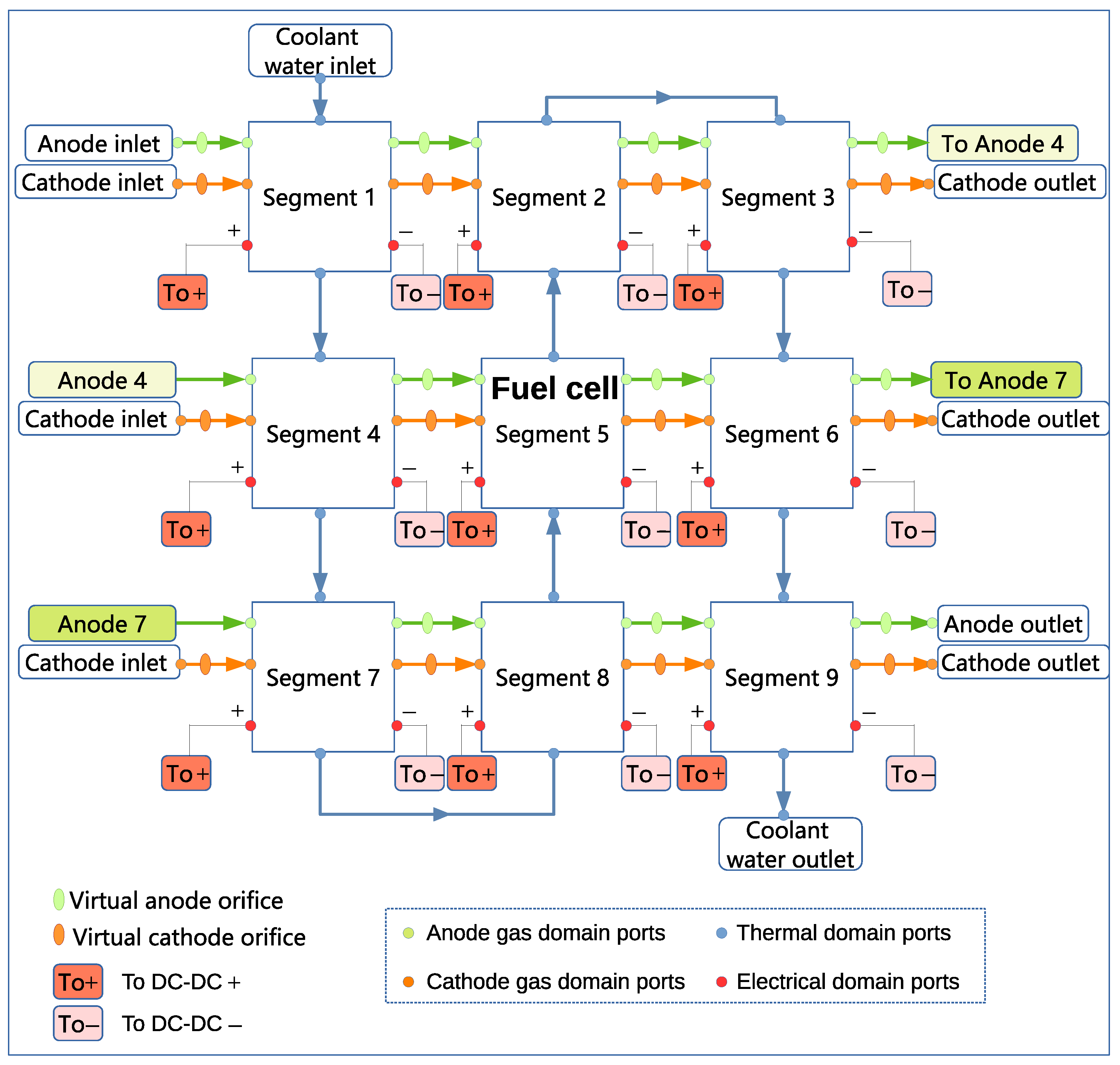
2.5. Single/Segmented Fuel Cell–Battery Hybrid Power System

Utilizing the physical modeling concept, the system model was built with the electrical ports connected, as shown in Figure 3. All voltages and currents were equalized automatically, so the structure could be reconstructed easily.
  • Fuel cell: output voltage V f c and current i f c should be coupled according to the polarization curve to satisfy the fuel cell’s characteristics.
  • Battery: output voltage V b a t t e r y and current i b a t t e r y should be coupled according to the battery charge–discharge curve to satisfy the battery’s characteristics. V b a t t e r y is related to its open-circuit voltage E b a t t e r y , SOC, and current demand.
  • DC-DC converter: it obeys the law of conservation of energy.
  • Load: the output voltages of the load ( V L o a d ), battery ( V b a t t e r y ), and DC-DC ( V D C D C ) converter are equal. The load gives the total current demand i L o a d , the output current i D C D C is allocated by the EMS, and the battery complements the residual current demand automatically. When the load demand is smaller than i D C D C , i b a t t e r y turns negative and the battery is charged.
The fuel cell with 3 × 3 segments is shown in Figure 4. The segments are connected with electrical, gas, and thermal domain ports, and parallel-connected to the external DC-DC converter with electrical ports. Since the segments are produced as a lumped parameter model, several virtual orifices are added to simulate the pressure drop in the gas flow channels. Since the model is highly scalable, more segment applications can be simulated for different system analysis requirements.

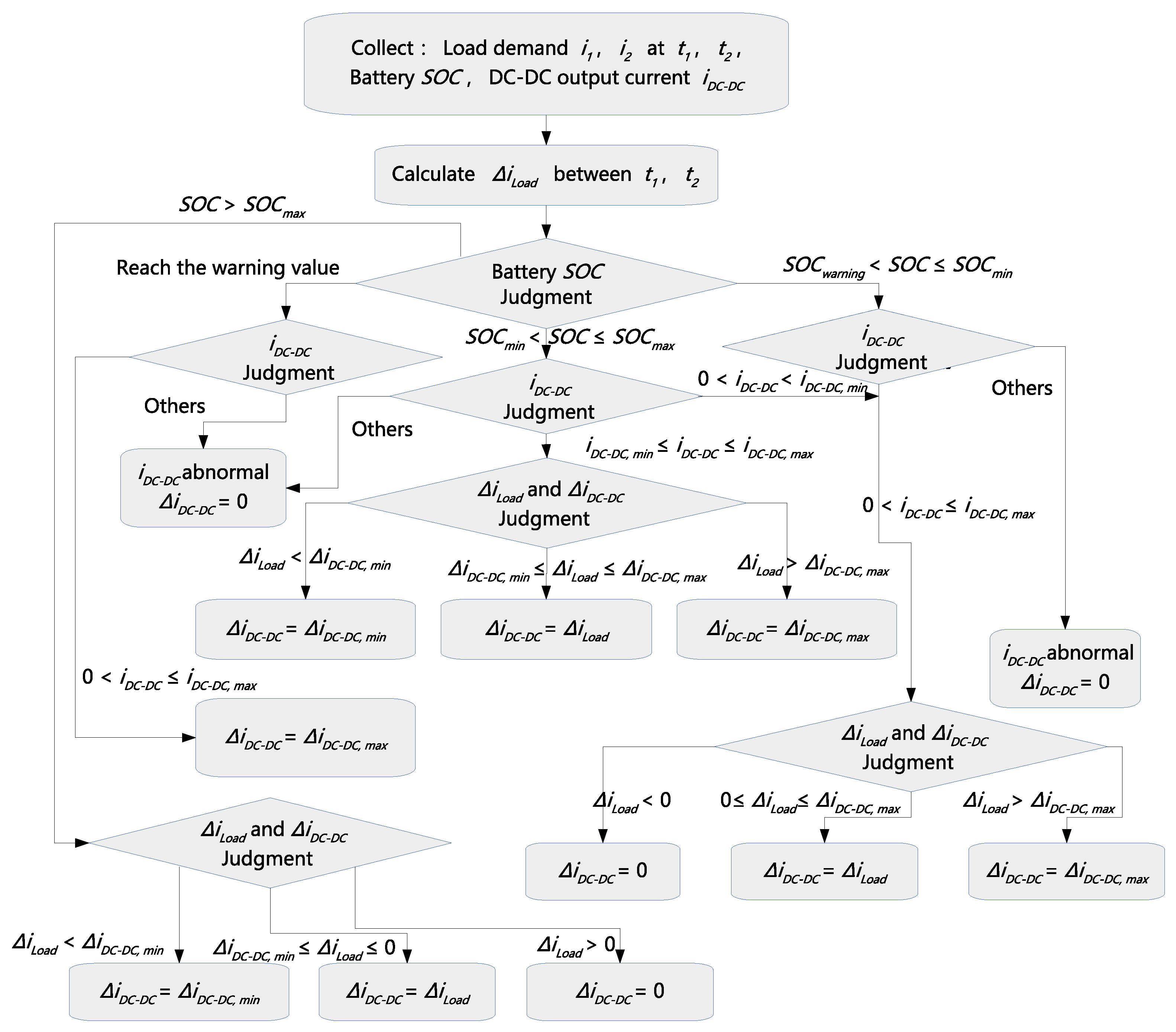
3. Energy Management Strategy

To distribute the power demand reasonably, the system operation’s objectives are listed as follows:
  • The load current demand should be satisfied during dynamic scenarios.
  • The rate of current change demand of the FC should be maintained within an appropriate range by considering its dynamic constraints. Correspondingly, a limitation on the rate of current change demand for the DC-DC converter should be set.
  • The output current of the FC has limitations. Correspondingly, the DC-DC converter output current should be limited.
  • The SOC should be above the warning line and maintained within an appropriate range to keep the battery’s output voltage in a relatively stable state.
Inspired by [26], five operation modes are defined. The flow chart is shown in Figure 5. Since the future load current demand is assumed to be unknown, the load current demand i 1 and i 2 at t 1 and t 2 can be collected, and the current differential Δ i L o a d is used to estimate the rate of current change.
  • Mode 1: S O C ( S O C M i n , S O C M a x ] & i D C D C [ i D C D C , M i n , i D C D C , M a x ] . The fuel cell tries to satisfy the load current demand with the limitation of the DC-DC converter’s rate of current change.
    Δ i D C D C = Δ i D C D C , M a x i f Δ i L o a d > Δ i D C D C , M a x Δ i L o a d i f Δ i L o a d [ Δ i D C D C , M i n , Δ i D C D C , M a x ] Δ i D C D C , M i n i f Δ i L o a d < Δ i D C D C , M i n
  • Mode 2: S O C ( S O C M i n , S O C M a x ] & i D C D C ( 0 , i D C D C , M i n ) . The fuel cell should follow the change in load current demand and reach its appropriate operating state.
    Δ i D C D C = Δ i D C D C , M a x i f Δ i L o a d > Δ i D C D C , M a x Δ i L o a d i f Δ i L o a d [ 0 , Δ i D C D C , M a x ] 0 i f Δ i L o a d < 0
  • Mode 3: S O C ( S O C w a r n i n g , S O C M i n ] & i L o a d < i D C D C , M a x . The battery needs charging.
    Δ i D C D C = Δ i D C D C , M a x i f Δ i L o a d > Δ i D C D C , M a x Δ i L o a d i f Δ i L o a d [ 0 , Δ i D C D C , M a x ] 0 i f Δ i L o a d < 0
  • Mode 4: The SOC of the battery reaches the warning line. In this case, the battery must charge, Δ i D C D C = Δ i D C D C , M a x .
  • Mode 5: S O C > S O C M a x . In this case, excessive charging should be avoided, and the output current of the DC-DC converter should be appropriately reduced. If the load current demand is low (idle, start–stop phase), the fuel cell output current can be reduced below the appropriate operating current.
    Δ i D C D C = 0 i f Δ i L o a d > 0 Δ i L o a d i f Δ i L o a d [ Δ i D C D C , M i n , 0 ] Δ i D C D C , M i n i f Δ i L o a d < Δ i D C D C , M i n

4. Simulation Results and Discussions

To validate the single/segmented fuel cell hybrid system’s performance, simulations were conducted within Matlab/Simscape. Some parameters were set as shown in Table 1, which could be revised based on the system’s characteristics and operation objectives. Three sets of simulations were conducted as follows:
  • Performance of the single-fuel-cell hybrid power system.
  • Performance of the single-fuel-cell hybrid power system with a low-battery SOC situation.
  • Performance of the ( 3 × 3 )-segment fuel cell hybrid power system.

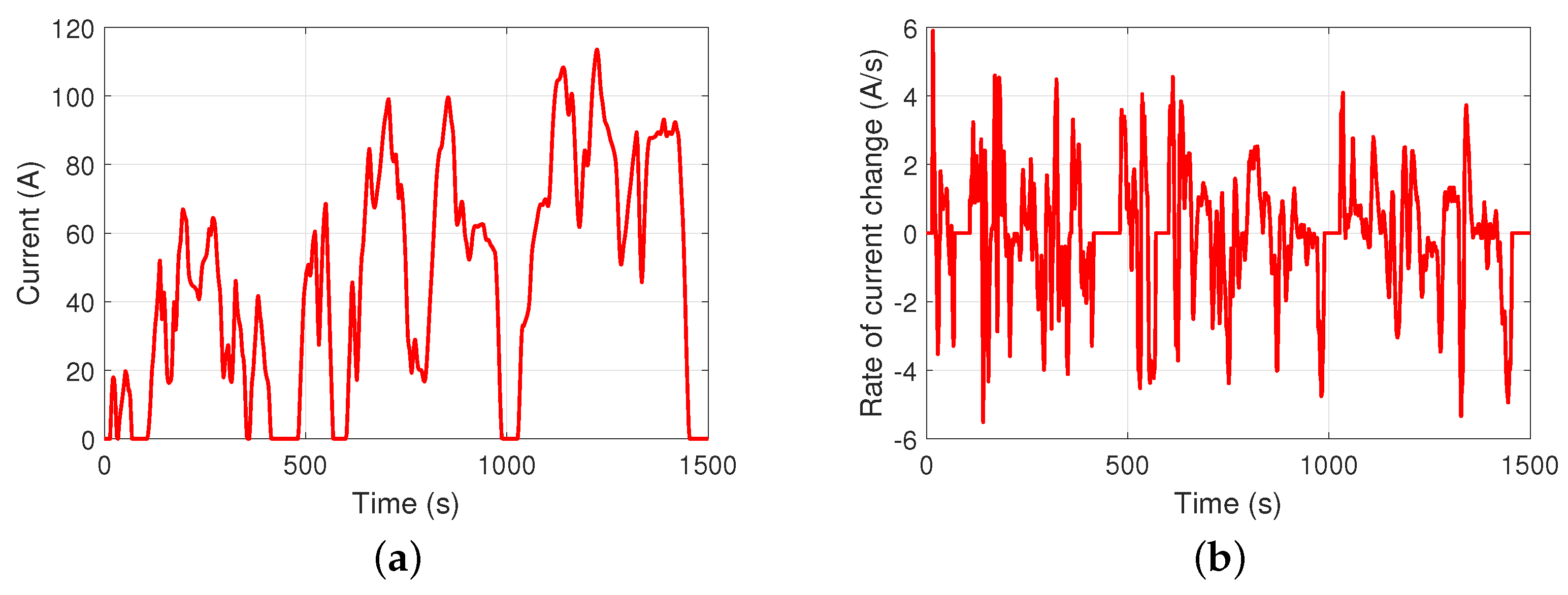
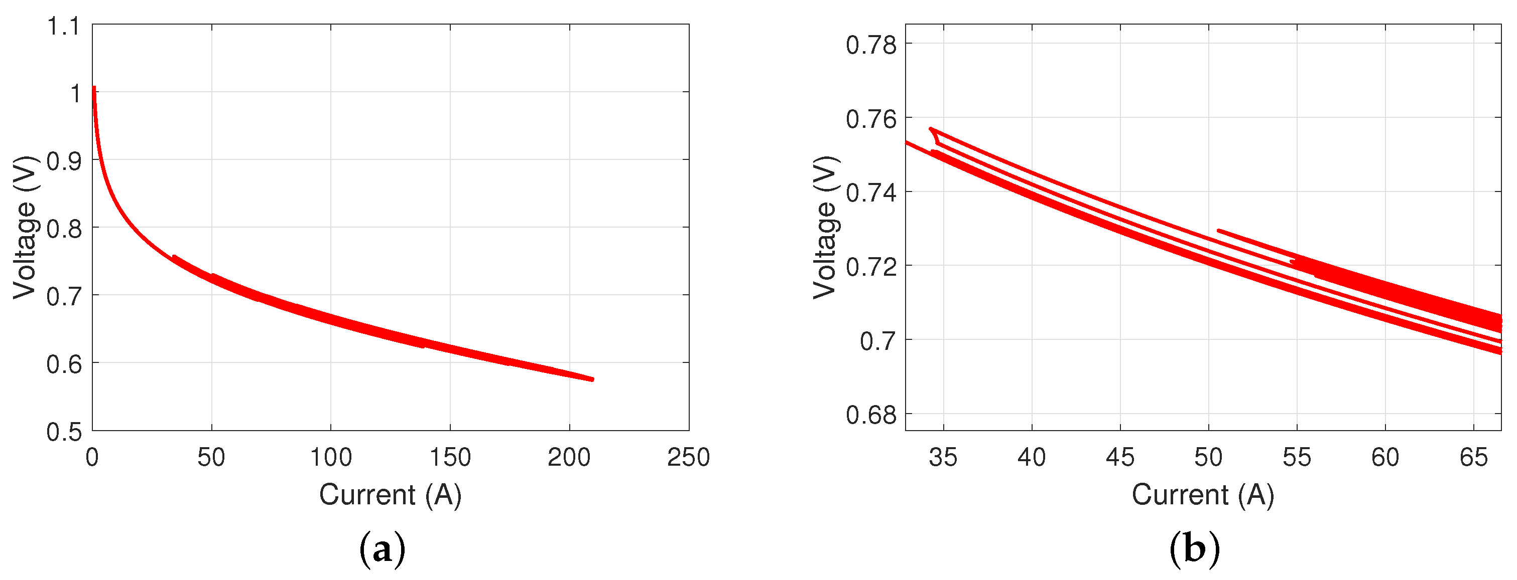
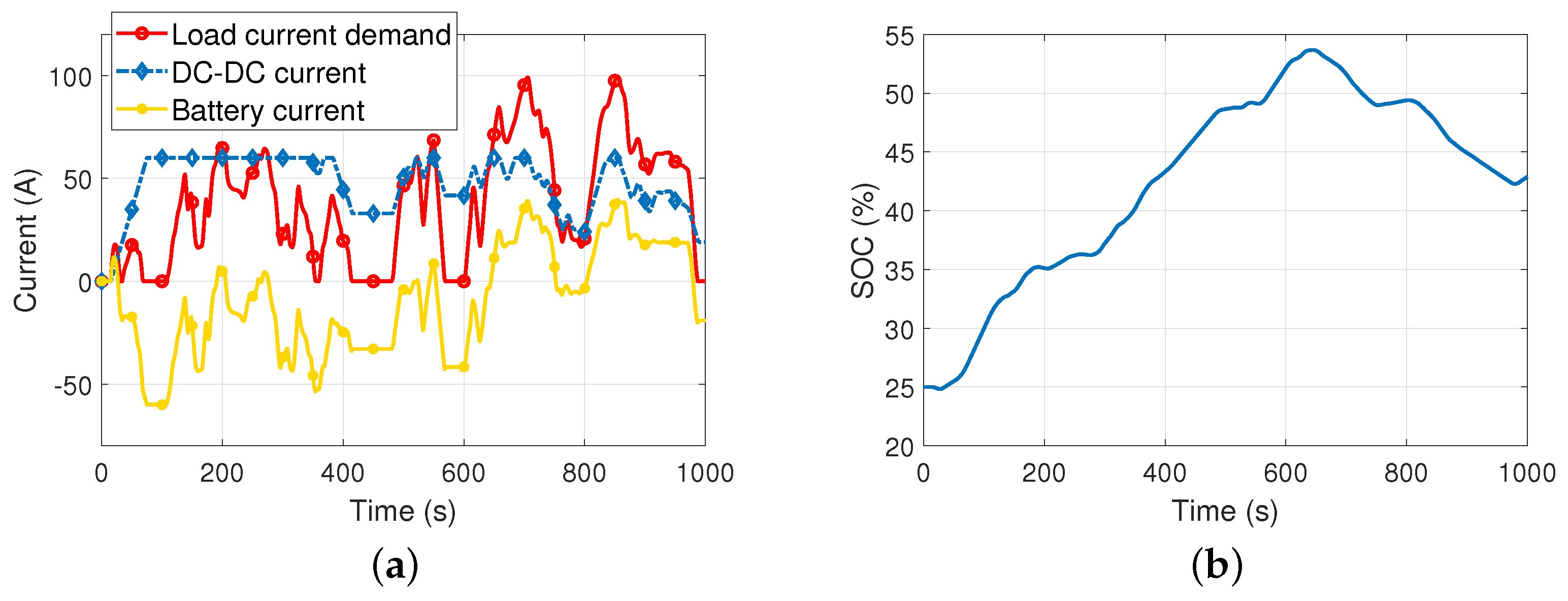
4.1. Single-Fuel-Cell Hybrid Power System

A typical dynamic load current demand is shown as Figure 6a, which changes frequently and has several no-current-demand sections. The hybrid power system starts at 15 s. According to its characteristics, the current demand can be divided into three parts.
  • Part 1 (0–500 s): low current demand and several no-current-demand sections.
  • Part 2 (500–1000 s): the current demand increases, and the fluctuation becomes more drastic.
  • Part 3 (1000–1500 s): small current fluctuation, and the average power demand is the largest among the three parts.
The rate of load current demand change is shown in Figure 6b, which exceeds the reasonable operating range of the rate of the DC-DC output current change.
Figure 7 shows the output current of the load, DC-DC converted, and battery. The simulation result shows that in part 1, the DC-DC converter can basically satisfy the load current demand. The battery is charged when the load current demand is zero or drops rapidly. The battery only supplies power when Δ i L o a d < Δ i D C D C , M a x . In part 2, the DC-DC output current almost reaches its peak value and the battery has to provide the remaining current demand. Similar to part 1, the battery is charged during zero-current-demand sections. In part 3, the DC-DC current remains at a high level. In particular, when the load current demand approaches zero around 1450 s, the fuel cell continues to charge the battery.
Figure 8a–c show the current, voltage, and rate of current change of the FC and DC-DC converter, respectively. The DC-DC converter works as a boosting transformer. The rates of current change of both DC-DC converter and FC conform to the system operation’s objectives. Figure 8d shows the battery SOC, which conforms to the results of the battery output current.
The polarization curve of the fuel cell is shown in Figure 9a, which works within the appropriate range. In particular, Figure 9b is the partial enlargement of the polarization curve, which shows that one voltage might correspond to multiple currents and one current might correspond to multiple voltages. This is because the fuel cell’s temperature changes during the whole operation process, which affects its volt-ampere characteristics.

4.2. Single-Fuel-Cell Hybrid Power System with Low-Battery SOC Situation
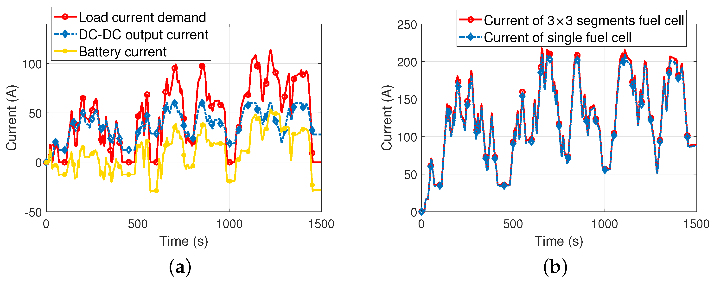
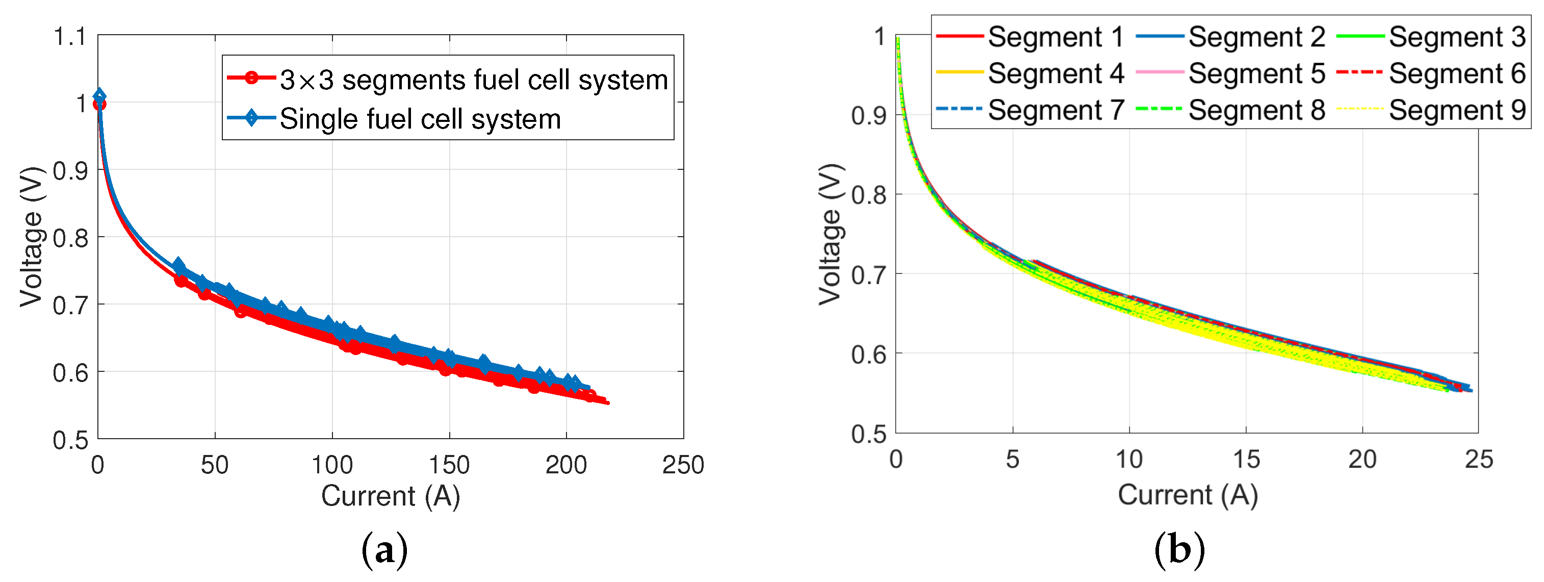
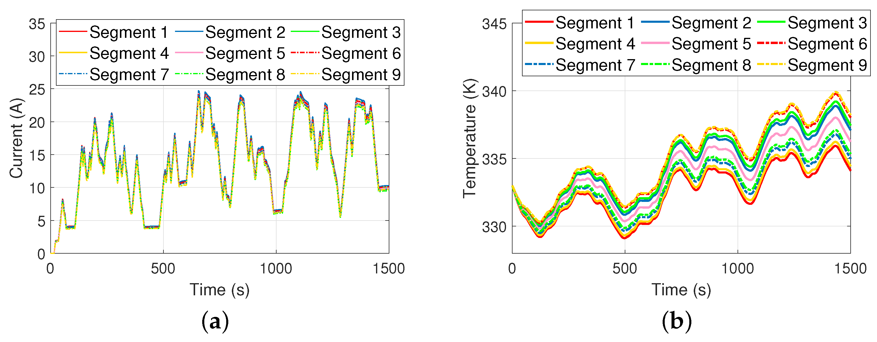
To simulate the system performance during a low-battery SOC situation, the initial battery SOC was set as 25 % , which is lower than the warning line ( 30 % ). According to mode 4, the battery must be charged and Δ i D C D C = Δ i D C D C , M a x . Figure 10a shows the current of the load, DC-DC converter, and battery during the low-battery SOC situation, and Figure 10b shows the battery SOC.
In order to charge the battery, the DC-DC converter’s rate of current change climbs to its maximum value until it reaches a DC-DC maximum output current of 60 A. The battery SOC rises to 30 % at around 100 s but is still less than 40 % . According to mode 3, the DC-DC current is not decreased, and the battery is charged as well, which ensures that the battery SOC remains in a favorable range and is ready for instantaneous high power requirements. Around 350 s, the SOC reaches 40 % , and then the system returns to normal situations.

4.3. Hybrid Power System with ( 3 × 3 )-Segment Fuel Cell

To validate the segmentation scalability of the proposed model, the same load current demand and EMS were used in simulations of the ( 3 × 3 )-segment fuel cell hybrid power system. The load current demand, DC-DC output current, and battery current are shown in Figure 11a, which is exactly the same as Figure 7. Figure 11b shows the comparison of the total output current in both systems. Although in both systems, the DC-DC output current and voltage are the same, both fuel cell currents still show a small difference. The maximum currents of the single/segmented system are 217.7 A/ 209.3 A with a 4% error, which is tolerable because of the system’s temperature differences. Figure 12a shows the polarization curve of both systems, which are quite similar. Figure 12b shows the polarization curve of nine segments. In both single/segmented systems, one voltage might correspond to multiple currents and one current might correspond to multiple voltages because of their temperature changes. Actually, the segmented fuel cell’s polarization curve is a summation of the nine segments’ polarization curves. The main reason behind the difference between those polarization curves is the temperature changes and distribution.
Figure 13a,b show the current and temperature distributions of the nine segments, respectively. In this work, the gas supply was assumed to be stable and abundant, and the current distribution was mainly affected by the temperature. Based on proper thermal and gas supply environments, the current distribution is basically uniform. Figure 13b shows that the temperature sequence of the nine segments is directly affected by the coolant water flow sequence. The temperature difference is affected by the coolant water flow rate, temperature, and the model’s heat transfer parameters.
The hybrid power system with the EMS has a positive influence on the fuel cell current and temperature uniformity. A system with only a segmented fuel cell was developed as a comparison to provide the same load current demand and a standard output voltage of 1.8 V. Some important data are listed in Table 2. Obviously, to satisfy the same load demand, the fuel-cell-only system’s output currents of the nine segments are higher, and so are the temperatures. The temperature sequence among the nine segments in both hybrid system/single-fuel-cell system are the same. The variance integrals of the nine segments’ current and temperature show that the hybrid power system with the EMS has more uniform current and temperature distributions.

5. Conclusions

This paper developed a dynamic, scalable, segmented fuel cell–battery hybrid power system model. The proposed model was able to predict the current and temperature distributions in the fuel cell during dynamic load scenarios. Based on the concept of physical modeling, submodels (FC, battery, DC-DC converter, load) were connected with physical ports and balanced the variables automatically. Based on the model, a real-time energy management framework was designed to validate the performance of both single and ( 3 × 3 )-segment fuel cell hybrid power systems. Simulation results showed that the proposed EMS had good performance on both single/segmented fuel cell–battery hybrid systems and the low-battery SOC situation. In particular, simulation results showed that the maximum current error of the single/segmented system was 4%. The comparison between single and segmented fuel cells showed the scalability of the proposed model, which provides an approach whereby with an interconnected ODE system, both controller design and system analysis requirements can be satisfied.

Author Contributions

Conceptualization, L.H.; methodology, L.H., Q.O. and J.C.; software, L.H. and Q.O.; validation, L.H. and Z.L.; data curation, L.H. and Q.O.; writing—original draft preparation, L.H.; writing—review and editing, L.H., Q.O., J.C., Z.L. and X.W. All authors have read and agreed to the published version of the manuscript.

Funding

This research was funded in part by the Natural Science Foundation of Zhejiang Province under grant LQ22F030010, in part by the Key Research and Development Program of Zhejiang Province under grant 2021C01098, and in part by the National Natural Science Foundation of China under grant 62203382.

Data Availability Statement

Not applicable.

Conflicts of Interest

The authors declare no conflict of interest.

References

  1. Hu, Z.; Li, J.; Xu, L.; Song, Z.; Fang, C.; Ouyang, M.; Dou, G.; Kou, G. Multi-objective energy management optimization and parameter sizing for proton exchange membrane hybrid fuel cell vehicles. Energy Convers. Manag. 2016, 129, 108–121. [Google Scholar] [CrossRef]
  2. Jiang, W.; Fahimi, B. Active Current Sharing and Source Management in Fuel Cell–Battery Hybrid Power System. IEEE Trans. Ind. Electron. 2010, 57, 752–761. [Google Scholar] [CrossRef]
  3. Huang, L.; Chen, J.; Liu, Z.; Becherif, M. Adaptive thermal control for PEMFC systems with guaranteed performance. Int. J. Hydrogen Energy 2018, 43, 11550–11558. [Google Scholar] [CrossRef]
  4. Chen, J.; Huang, L.; Yan, C.; Liu, Z. A dynamic scalable segmented model of PEM fuel cell systems with two-phase water flow. Math. Comput. Simulat. 2020, 167, 48–64. [Google Scholar] [CrossRef]
  5. Li, Q.; Chen, W.; Liu, Z.; Li, M.; Ma, L. Development of energy management system based on a power sharing strategy for a fuel cell-battery-supercapacitor hybrid tramway. J. Power Sources 2015, 279, 267–280. [Google Scholar] [CrossRef]
  6. Wu, C.; Chen, J.; Xu, C.; Liu, Z. Real-Time Adaptive Control of a Fuel Cell/Battery Hybrid Power System with Guaranteed Stability. IEEE Trans. Control Syst. Technol. 2017, 25, 1394–1405. [Google Scholar] [CrossRef]
  7. Meng, X.; Li, Q.; Zhang, G.; Wang, T.; Chen, W.; Cao, T. A Dual-Mode Energy Management Strategy Considering Fuel Cell Degradation for Energy Consumption and Fuel Cell Efficiency Comprehensive Optimization of Hybrid Vehicle. IEEE Access 2019, 7, 134475–134487. [Google Scholar] [CrossRef]
  8. Li, Q.; Wang, T.; Dai, C.; Chen, W.; Ma, L. Power Management Strategy based on Adaptive Droop Control for a Fuel Cell-Battery-Supercapacitor Hybrid Tramway. IEEE Trans. Veh. Technol. 2018, 67, 5658–5670. [Google Scholar] [CrossRef]
  9. Hu, X.; Murgovski, N.; Johannesson, L.M.; Egardt, B. Optimal Dimensioning and Power Management of a Fuel Cell/Battery Hybrid Bus via Convex Programming. IEEE/ASME Trans. Mechatron. 2014, 20, 457–468. [Google Scholar] [CrossRef]
  10. Xu, L.; Mueller, C.D.; Li, J.; Hu, Z.; Ouyang, M. Multi-objective component sizing based on optimal energy management strategy of fuel cell electric vehicles. Appl. Energy 2015, 157, 664–674. [Google Scholar] [CrossRef]
  11. Fernandez, L.M.; Garcia, P.; Garcia, C.A.; Francisco, J. Hybrid electric system based on fuel cell and battery and integrating a single dc/dc converter for a tramway. Energy Convers. Manag. 2011, 52, 2183–2192. [Google Scholar] [CrossRef]
  12. Simmons, K.; Guezennec, Y.; Onori, S. Modeling and energy management control design for a fuel cell hybrid passenger bus. J. Power Sources 2014, 246, 736–746. [Google Scholar] [CrossRef]
  13. Li, Q.; Su, B.; Pu, Y.; Han, Y.; Chen, W. A state machine control based on equivalent consumption minimization for fuel cell/supercapacitor hybrid tramway. IEEE T. Transp. Electr. 2019, 5, 552–564. [Google Scholar] [CrossRef]
  14. Wang, T.; Qiu, Y.; Yin, L.; Liu, L. Efficiency extreme point tracking strategy based on FFRLS online identification for pemfc system. IEEE Trans. Energy Convers. 2019, 34, 952–963. [Google Scholar] [CrossRef]
  15. Hu, X.; Liu, S.; Song, K.; Gao, Y.; Zhang, T. Novel fuzzy control energy management strategy for fuel cell hybrid electric vehicles considering state of health. Energies 2021, 14, 6481. [Google Scholar] [CrossRef]
  16. Jaafar, A.; Turpin, C.; Roboam, X.; Bru, E.; Rallieres, O. Energy management of a hybrid system based on a fuel cell and a Lithium Ion battery: Experimental tests and integrated optimal design. Math. Comput. Simulat. 2017, 131, 21–37. [Google Scholar] [CrossRef]
  17. Kandidayeni, M.; Macias, A.; Boulon, L.; Kelouwani, S. Efficiency Enhancement of an Open Cathode Fuel Cell Through a Systemic Management. IEEE Trans. Veh. Technol. 2019, 68, 11462–11472. [Google Scholar] [CrossRef]
  18. Chen, J.; Xu, C.; Wu, C.; Xu, W. Adaptive Fuzzy Logic Control of Fuel-Cell-Battery Hybrid Systems for Electric Vehicles. IEEE Trans. Industr. Inform. 2018, 14, 292–300. [Google Scholar] [CrossRef]
  19. Yan, Y.; Li, Q.; Chen, W.; Huang, W.; Liu, J. Hierarchical Management Control Based on Equivalent Fitting Circle and Equivalent Energy Consumption Method for Multiple Fuel Cells Hybrid Power System. IEEE Trans. Ind. Electron. 2019, 67, 2786–2797. [Google Scholar] [CrossRef]
  20. Yan, Y.; Li, Q.; Chen, W.; Su, B.; Liu, J.; Ma, L. Optimal Energy Management and Control in Multimode Equivalent Energy Consumption of Fuel Cell/Supercapacitor of Hybrid Electric Tram. IEEE Trans. Ind. Electron. 2019, 66, 6065–6076. [Google Scholar] [CrossRef]
  21. Sellali, M.; Ravey, A.; Betka, A.; Kouzou, A.; Benbouzid, M.; Djerdir, A.; Kennel, R.; Abdelrahem, M. Multi-objective optimization-based health-conscious predictive energy management strategy for fuel cell hybrid electric vehicles. Energies 2022, 15, 1318. [Google Scholar] [CrossRef]
  22. Jia, J.; Li, Q.; Wang, Y.; Cham, Y.T.; Han, M. Modeling and Dynamic Characteristic Simulation of a Proton Exchange Membrane Fuel Cell. IEEE Trans. Energy Convers. 2009, 24, 283–291. [Google Scholar] [CrossRef]
  23. Mann, R.; Amphlett, J.; Hooper, M.; Jensen, H.; Peppley, B.; Roberge, P. Development and application of a generalized steady-state electrochemical model for a pem fuel cell.journal of power sources. J. Power Sources 2000, 86, 173–180. [Google Scholar] [CrossRef]
  24. Beater, P. Pneumatic Drives/System Design, Modelling and Control; Springer: Berlin/Heidelberg, Germany, 2007; pp. 30–35. [Google Scholar]
  25. Battery. MATLAB/Simscape. Available online: https://ww2.mathworks.cn/help/sps/powersys/ref/battery.html (accessed on 1 August 2023).
  26. Han, Y.; Li, Q.; Wang, T.; Chen, W.; Ma, L. Multisource Coordination Energy Management Strategy Based on SOC Consensus for a PEMFC–Battery–Supercapacitor Hybrid Tramway. IEEE Trans. Veh. Technol. 2018, 67, 296–305. [Google Scholar] [CrossRef]
Figure 1. System structure.
Energies 16 06224 g001
Figure 2. A example of ideal voltage source—ideal resistance circuit with physical and mathematical modeling concepts.
Energies 16 06224 g002
Figure 3. Hybrid power system model.
Energies 16 06224 g003
Figure 4. Segmented fuel cell in a hybrid power system model.
Energies 16 06224 g004
Figure 5. Flow chart of the EMS.
Energies 16 06224 g005
Figure 6. Load current demand and its rate of change: (a) load current demand; (b) rate of load current demand change.
Energies 16 06224 g006
Figure 7. Load current demand, DC-DC output current, and battery current.
Energies 16 06224 g007
Figure 8. System performance: (a) current of fuel cell and DC-DC converter; (b) voltage of fuel cell and DC-DC converter; (c) rate of current change of fuel cell and DC-DC converter; (d) SOC of battery.
Energies 16 06224 g008
Figure 9. Polarization curve of the fuel cell: (a) polarization curve; (b) partial enlargement.
Energies 16 06224 g009
Figure 10. Simulations of low-battery SOC situation: (a) current of load, DC-DC converter, and battery; (b) battery SOC.
Energies 16 06224 g010
Figure 11. Comparison between single/segmented fuel cell hybrid power systems. (a) Current of load, DC-DC converter, and battery of the segmented fuel cell hybrid power system; (b) current of the fuel cell.
Energies 16 06224 g011
Figure 12. Polarization curve: (a) single and segmented fuel cell; (b) 9 segments.
Energies 16 06224 g012
Figure 13. (a) Current distribution; (b) temperature distribution.
Energies 16 06224 g013
Table 1. Parameters.
ParametersValuesParametersValues
i D C D C , M i n 10 A i D C D C , M a x 60 A
Δ i D C D C , M i n 1  A/s Δ i D C D C , M a x 1 A/s
S O C M i n 40 % S O C M a x 80 %
S O C w a r n i n g 30 % S O C i n i t i a l 70 %
η l o s e 95 %
Table 2. Comparison between the fuel cell in the hybrid power system and only a fuel cell.
Fuel Cell in Hybrid
Power System
Max Current/AMax Temperature/KOnly a Fuel CellMax Current/AMax Temperature/K
Segment 1 24.6 335.9 Segment 1 62.34 349.9
Segment 2 24.7 338.9 Segment 2 63.52 355.2
Segment 3 24.25 339.2 Segment 3 62.93 356
Segment 4 24.16 336.2 Segment 4 61.89 350.5
Segment 5 24.25 338Segment 5 62.59 353.6
Segment 6 25.26 339.8 Segment 6 63.16 357.2
Segment 7 24.14 336.8 Segment 7 62.09 351.5
Segment 8 23.68 337.1 Segment 8 61.51 352.1
Segment 9 23.62 339.9 Segment 9 62.38 357.7
Average 24.19 338Average 62.49 353.5
Variance integral (nondimensional) 98.73 1561Variance integral (nondimensional) 195.8 3839
Disclaimer/Publisher’s Note: The statements, opinions and data contained in all publications are solely those of the individual author(s) and contributor(s) and not of MDPI and/or the editor(s). MDPI and/or the editor(s) disclaim responsibility for any injury to people or property resulting from any ideas, methods, instructions or products referred to in the content.

