Article

Proposing a Hybrid BTMS Using a Novel Structure of a Microchannel Cold Plate and PCM

by
Moeed Rabiei
1,
Ayat Gharehghani
1,*,
Soheil Saeedipour
1,
Amin Mahmoudzadeh Andwari
2,* and
Juho Könnö
2
1
School of Mechanical Engineering, Iran University of Science and Technology, Narmak, Tehran 16846, Iran
2
Machine and Vehicle Design (MVD), Materials and Mechanical Engineering, Faculty of Technology, University of Oulu, FI-90014 Oulu, Finland
*
Authors to whom correspondence should be addressed.
Energies 2023, 16(17), 6238; https://doi.org/10.3390/en16176238
Submission received: 24 July 2023 / Revised: 22 August 2023 / Accepted: 25 August 2023 / Published: 28 August 2023

Abstract

:
The battery thermal management system (BTMS) for lithium-ion batteries can provide proper operation conditions by implementing metal cold plates containing channels on both sides of the battery cell, making it a more effective cooling system. The efficient design of channels can improve thermal performance without any excessive energy consumption. In addition, utilizing phase change material (PCM) as a passive cooling system enhances BTMS performance, which led to a hybrid cooling system. In this study, a novel design of a microchannel distribution path where each microchannel branched into two channels 40 mm before the outlet port to increase thermal contact between the battery cell and microchannels is proposed. In addition, a hybrid cooling system integrated with PCM in the critical zone of the battery cell is designed. Numerical investigation was performed under a 5C discharge rate, three environmental conditions, and a specific range of inlet velocity (0.1 m/s to 1 m/s). Results revealed that a branched microchannel can effectively improve thermal contact between the battery cell and microchannel in a hot area of the battery cell around the outlet port of channels. The designed cooling system reduces the maximum temperature of the battery cell by 2.43 °C, while temperature difference reduces by 5.22 °C compared to the straight microchannel. Furthermore, adding PCM led to more uniform temperature distribution inside battery cell without extra energy consumption.

1. Introduction

Lithium-ion batteries are crucial in terms of voltage, energy density, self-discharge rate, and cycle life when compared to other energy storage batteries. Their unique properties make them essential for electric vehicles (EVs) and energy storage systems [1]. With the advancement of battery materials and structures, the energy density of lithium-ion batteries has been steadily increasing. As of 2020, the average energy density has reached 300 Wh/kg [2]. Improving the energy density of batteries leads to a higher demand for thermal safety. However, temperature dramatically affects the performance and lifespan of lithium-ion batteries. Low temperatures cause a decrease in battery capacity by slowing down the chemical reaction rate and increasing internal resistance [3,4]. Raised temperatures expedite the deterioration of the battery’s structural components, decreasing battery performance and lifespan. This also leads to a drop in thermal safety and can even cause battery thermal runaway [5,6]. Implementing a suitable BTMS is critical to ensure the reliable operation of battery-powered electric vehicles. BTMS keeps thermal safety, battery performance, and longevity while preventing thermal runaway [7]. Consequently, developing a BTMS to maintain the battery temperature within the optimal range of 20 °C–50 °C and improve temperature uniformity is essential [8,9]. Lithium-ion batteries use three types of thermal management: active cooling, passive cooling, and hybrid cooling. The active cooling method involves the consumption of energy to manage temperature, which is achieved through techniques such as water-cooling or air-cooling thermal management systems [10,11]. Conversely, the passive cooling technique involves temperature management without energy expenditure, typically utilizing materials with high thermal storage capacity, such as PCM [12,13]. Many scholars have extensively researched the air-cooling method and battery layout. For example, Sharma et al. [14,15] studied the effect of air inlet placement on cylindrical battery temperature using forced air cooling. Results showed that bi-directional air intake reduced battery temperature differences and decreased fan energy consumption. Wang et al. [16] enhanced the cooling efficiency of the air-cooled battery BTMS in electric vehicles using parallel plates. The optimal model had two parallel plates with an optimal length and height of 1.5 and 30 mm. As a result of three optimization schemes, Tmax and ΔTmax were reduced by 3.37 K and 5.5 K, respectively. Widyantara et al. [17] introduced an air-cooling system to modify the number of cooling fans and the inlet air temperature. The numerical model of 74 V and 2.31 kWh battery packing was simulated using the lattice Boltzmann method. Results demonstrated that three cooling fans with a 25 °C inlet air temperature achieved the best performance with low power required. The optimized configuration kept all battery cells inside the optimal temperature range, even though the maximum temperature difference was still 15 °C. Liquid cooling systems are more efficient for heat transfer than air cooling systems due to the better thermal conductivity of liquids. They can cool batteries directly with a highly thermally conductive and insulating liquid or indirectly via a cooling plate [18,19]. Wang et al. [20] compared the thermal performance of parallel and serial flow types of BTMS. The parallel flow channel cooling method showed a more uniform temperature distribution, with an optimized layout of parallel channels maintaining the maximum battery temperature below 36 °C while keeping the maximum temperature difference within 4.17 °C at a 3C discharge rate. The U-shaped lightweight liquid cooling method developed by Li et al. [21] improves the thermal safety and weight optimization of prismatic battery cells. It led to a 21% decrease in maximum battery temperature and a 45% reduction in cooling plate weight, showing promise for electric vehicle use. Magnini and Thome [22] researched the effect of flow parameters on heat transfer in slug flow boiling in microchannels. They found that a thin liquid film and a short liquid slug enhance the heat transfer coefficient. Li et al. [23] studied the flow patterns of R1234ze(E) in a microchannel tube. The results showed that due to its lower vapor density, the annular flow starts at a lower quality for R1234ze(E) than R32 and R134a. Oil spray cooling for end winding thermal management was studied by Wang et al. [24] The presence of oil spray was effective in maintaining safe winding temperature under higher heat loads, with elevated flow rates and spray temperatures resulting in more uniform temperature distribution. Jayarajan and Azimov [25] proposed a zig-zag serpentine flow pattern design for cold plates, optimizing several parameters for six different designs. The five-channel design with 18 mm channel width and the seven-channel design with 16 mm width were the best configurations, and the highest temperature at the exit region was 330.84 K for the design with three channels. To enhance the thermal performance of battery modules in EVs and reduce power consumption, Wei et al. [26] optimized the heat transfer of liquid cold plates with serpentine channels. The results showed that by maintaining the pressure drop below 1000 Pa, the maximum temperature differences for discharging rates at 1 C, 2 C, 3 C, and 4 C were controlled within 0.29 K, 1.11 K, 2.17 K, and 3.43 K, respectively. To improve the heat transfer between the battery bottom and the cold plate, Dong et al. [27] designed a wavy channel, which reduced the maximum temperature of the battery module by 1.75 °C compared to the straight-channel design. Lee and Garimella [28] presented an experimental investigation of saturated flow boiling heat transfer in microchannel heat sinks. Their results demonstrated that the pressure drop across the microchannels increases rapidly with heat flux, and the local heat transfer coefficient increases almost linearly with heat flux at low to medium heat fluxes. Li et al. [29] presented the heat transfer coefficient and pressure drop of R32 in a 24-port microchannel tube. The results showed that R32 has a higher heat transfer coefficient and lower pressure drop than R134a. Lin et al. [30] proposed a composite silica gel (CSG) coupled with a cross-structure mini-channel cold plate as a cooling system for battery modules. Results showed that the CSG-based liquid system can control the temperature below 45 °C and maintain the temperature difference within 2 °C at a 3C discharge rate. Worwood et al. [31] presented a novel graphite-based fin material for cooling large format pouch-type batteries, with an in-plane thermal conductivity five times greater than aluminum with the same weight. Results showed that the new fin can reduce the peak measured temperature and surface temperature gradient by up to 8 °C and 5 °C, respectively, when compared to aluminum fins under an aggressive electric vehicle duty cycle. In contrast to the active TMS, the passive method does not consume energy. This method’s most common cooling system type is heat pipe and PCM. PCM absorbs a significant amount of battery heat with a small volume change during phase change by its high latent heat. High thermal conductivity additives like aluminum wire, foam metal, carbon fiber, and graphite are commonly incorporated into composite Phase Change Materials (CPCM) to enhance thermal conductivity [32]. Huang et al. [33] suggested a flexible CPMC that helps reduce contact resistance in a battery thermal management system. The cooling efficiency of the BTMS was enhanced as the battery temperature decreased by 10 °C at an 18C discharge rate. V.G. Choudhari et al. [34] conducted a numerical analysis on a battery pack with a fin structure and PCM. The findings indicated that the fin structure led to an 8.17% reduction in the maximum battery temperature and increased heat transfer efficiency. Rabiei et al. [35] proposed six microchannel configurations composed of a wavy wall and metal foam embedded microchannel. The study indicated that the wavy wall microchannel performed better heat dissipation at a higher inlet velocity, while at a low inlet velocity, the metal foam embedded microchannel can cool down the battery cell with higher performance and lower power consumption. Ki et al. [36] developed a BTMS including a metal foam as a cooling passage in a 24-pouch cell battery module. The study revealed that with a 4.2 times lower flow rate, the system could attain an optimal temperature and temperature deviation of less than 2 °C. In a study conducted by Weng et al. [37], various fin structures such as V, Y, and X shapes were designed and utilized as heat flow channels in a PCM enclosure. The findings indicated that the X-shaped structure, which possessed an outstanding branched configuration, exhibited the most excellent thermal performance among the tested fin structures.
Based on the literature review, several methods have been explored to improve cooling systems. Using the liquid-cooling system, PCM alone has certain limitations, and combining liquid cooling as an active cooling method and PCM as a passive method has become a primary focus of researchers [38]. This paper presents a new liquid cooling system that utilizes a microchannel cold plate to manage the thermal conditions of a pouch Li-ion battery by an enhanced coolant distribution design. The primary objectives of this cooling system are to achieve a uniform temperature distribution across the batteries and to efficiently dissipate heat, which are crucial requirements for the effective thermal management of Li-ion batteries. The cooling system consists of inlets/outlets and a thermal conductive plate. The objective of reducing energy consumption and attaining the optimal battery temperature is followed through the proposal of an active and passive cooling system composed of a cooling plate and PCM. The cold plate cooling system comprises an inlet/outlet and a thermally conductive plate. To ensure a uniform temperature distribution in critical areas of the battery, where heat tends to accumulate at the end part, the feasibility of utilizing a Branch Micro-channel Cold Plate (BMCP) instead of a State Micro-channel Cold Plate (SMCP) is examined. BMCP improves heat transfer by increasing the surface area between the battery cell and coolant channels. The branching pattern of the microchannels creates a larger surface area for heat transfer, and the BMCP also enhances the mixing of the coolant. This is particularly effective in the critical zone, where the temperature difference between the cell and coolant is most significant [39]. Furthermore, this study analyzes the effect of operating parameters, including coolant inlet temperature and mass flow rate, on the cooling system. The temperature difference across the battery module and the maximum temperature inside the battery pack are also examined to ensure optimal thermal performance and prevent safety concerns. The findings of this study represent progress toward developing a BTMS with enhanced controllability. Table 1 compares the cooling system of the present study and recent studies. The following statements summarize the key concepts of this work:
  • The performance of BTMS was analyzed under active and passive cooling techniques using liquid, PCM, and BMCP.
  • To evaluate the effect of PCM on the heat dissipation performance of BTMS, the minimum value of PCM weight and ideal thermal performance are suggested.
  • To prevent thermal runaway, the effect of BMCP with SMCP has been studied as a factor that contributes to maintaining uniform temperature distribution in the cells.
  • To achieve the best design, the cooling capability has been analyzed under various environmental conditions to maintain the battery temperature within the optimal range.

2. Materials and Methods

2.1. Model Description

A Li-ion battery cell which used in Volkswagen and BMW i3 commercial EVs is selected for the present study. This battery cell is composed of a carbonate-based electrolyte, Cu cathode, and an Al anode with a capacity of 7 Ah. The battery has 45 mm width, 145 mm height, and 9mm thickness. The geometrical and thermodynamic characteristics of the battery cell are prepared in Table 2. This study investigates and analyzes a module consisting of ten battery cells, eleven cooling plates, and PCM (Figure 1). To reduce the computational cost and time, a half cell with a half cooling plate and microchannels is simulated and a symmetry boundary condition is applied. Information about the cold plate is provided in Table 3. Also, Table 4 presents the related characteristics of RT-27 PCM utilized in the present research. Specifically, a worst-case scenario involving a discharge rate of 5C is simulated to evaluate the thermal management system. To calculate the transient heat generation within the cells, a User-Defined Function (UDF) code was developed.

2.2. Governing Equations

The computational region is partitioned into three sub-regions: the cold plate (aluminum), the fluid part (water), and the battery cell. The governing equations for each of these sub-regions are formulated as follows.

2.2.1. Battery Cell

The generation heat of the battery cell fluctuates and depends on various factors, such as the size of the cell, state of charge (SOC), discharge rate, cell temperature, and electrochemical reaction rate. For this study, the relationship between heat production and electrical parameters, suggested by Bernarda et al. [47], was utilized. By utilizing the thermodynamic energy equation on a correlation derived from a complete cell, the following result is obtained:
Q ˙ = I U V I ( T   U T )
In the aforementioned equation, the variables T, U, Q ˙ , V, and I represent the cell temperature, open-circuit voltage, cell heat generation rate, terminal voltage, and electric current of cell, respectively.
Equation (1) can be restated as shown in previous studies [48,49]:
q ˙ = R i i 2 iT Δ S F
In the above equation, the variables F, Δ S , q ˙ , I, and R i represent Faraday number (96,485 C/mol), entropy change, rate of internal heat generation per unit volume, discharge current of cell per unit volume, and internal equivalent resistance, respectively. The internal equivalent resistance is influenced by the temperature and state of charge of the cell and can be mathematically represented as described in previous studies [48,49].
R i = 2.258 × 10 6   SOC 0.3952 T = 20   ° C 1.857 × 10 6   SOC 0.2787 T = 30   ° C 1.659 × 10 6   SOC 0.1692 T = 40   ° C
ΔS is dependent on the state of charge (SOC) and can be formulated as follows:
Δ S 99.88   S O C 76.97 0 S O C < 0.77 30 0.77 S O C < 0.87 20 0.87 S O C 1
The state of charge is defined as:
SOC = 1 I · t C 0
where C0 is the battery capacity, I is the discharge current, and t is the discharge duration (simulation starts at t = 0 and SOC = 1). Additionally, the energy conservation equation for a single cell is given by:
t ρ b C p , b T b = · k b T b + q ˙
where C p , b , k b , and ρ b are specific heat capacity, thermal conductivity, and density, respectively.

2.2.2. Coolant

The fluid section of the system is governed by the equations of mass, momentum, and energy conservation, which can be mathematically expressed as:
ρ f t + · ρ f v ¯ = 0
t ρ f v + · ρ f v v = p + · τ =
where p is the pressure.

2.2.3. Cold plate

The energy conservation equation for the solid domain cold plate can be mathematically expressed as follows:
t ρ s C p , s T s = · k s T s
where k s , ρ s , and C p , s are thermal conductivity, density, and heat capacity, respectively.

2.2.4. PCM

The enthalpy-porosity method is employed to model the phase change that occurs during the melting process of a solid into a liquid. During the phase change process, the energy equation is expressed as follows:
ρ H t = k   ( 2 T x 2 + 2 T x 2 ) + S
The enthalpy of the PCM is denoted by H and can be calculated using the following formula:
H = H 0 + H
The latent heat that exists between the solid and liquid phases is determined by utilizing the energy equation, which can be expressed through the following equations:
H 0 = H ref +   T ref T C p , PCM dT
H = β γ
γ = 0 , & &   T < T s T T S T l T S , &   T s < T < T l & 1 ,   &   T > T l
In these equations, S denotes the source term of the PCM, H represents the total enthalpy, and T indicates the temperature. The term H 0 means the sensible enthalpy, while H characterizes the latent heat content that changes between the solid and liquid phases.

2.3. Initial and Boundary Condition

At the beginning of the simulation, the ambient temperature was assigned to all domain temperatures. Three different ambient conditions (20 °C, 25 °C, and 35 °C) were considered for this study. A symmetric boundary condition was applied to both sides of the computational domain, as well as to all walls except for the inlet and outlet, which were treated as adiabatic walls. The velocity at the inlet was set to specific magnitudes (0.1, 0.3, 0.5, 0.7, and 1 m/s), the pressure at the microchannel outlet was set equal to the ambient pressure, and the fluid inlet temperature was set to the ambient temperature for each simulation.

3. Numerical Method and Mesh Independency

The ANSYS workbench is employed to generate a hexahedral structured mesh using appropriate processing tools for computational fluid dynamics (CFD) analysis. The governing equation is solved using a pressure-based solver in ANSYS Fluent software. To couple pressure and velocity, the SIMPLE algorithm is employed. The internal heat generation of the batteries is determined using a user-defined function (UDF) based on mathematical models. To ensure grid independence, three different grid sizes (150,000, 228,000, 380,000, and 454,000) were utilized for the computational domain. It was observed that the maximum temperature and PCM liquid fraction at 100 s, variation between the last two grids during discharge process with 5C discharge rate, 25 °C ambient temperature, and mass flow rate of 0.44 kg/hr was less than 5% and 5.7%, respectively. Figure 2 illustrates the variation of the maximum temperature for the various grids.

4. Validation of Numerical Model

In this study, validation was conducted for the battery cell section, cooling section, and PCM due to the use of different domains. The present study compares the mean temperature of a 100 Ah battery under natural air-cooling conditions at two different discharge rates, starting from an initial temperature of 20 °C with a convection heat transfer coefficient of 5 Wm−2K−1. The experimental results of Lin et al. [50] are also included in the comparison and illustrated in Figure 3a. Also, a comparison between the results of a microchannel with straight walls and the findings of Fan et al. [51] at varying flow rates during a 600-s discharge process at an ambient temperature of 27 °C was conducted. The comparison result is presented in Table 5. The maximum difference of 2.92% was achieved for the standard temperature deviation (SDT). SDT is calculated as:
STD = ( T max T avg ) 2 + ( T min T avg ) 2 2
In Figure 3b, the fraction of PCM melting is depicted over 18 min, and a comparison is made between the numerical results of this study and the experimental and numerical findings reported by Shmueli et al. [52]. Initially, the PCM starts melting at 22 °C when the adjacent walls’ temperature is above the fluid’s melting point at 30 °C. The numerical results obtained from this study have demonstrated acceptable accuracy with a deviation of less than 5% compared to the experimental data, as shown in Figure 3b.

5. Results and Discussion

This section presents a numerical investigation of the two proposed cold plates for a specific pouch LIB at a high discharge current of 5C for the water-cooling method by various inlet velocities of 0.1 m/s to 1 m/s and three ambient conditions of 20 °C, 25 °C, and 35 °C.

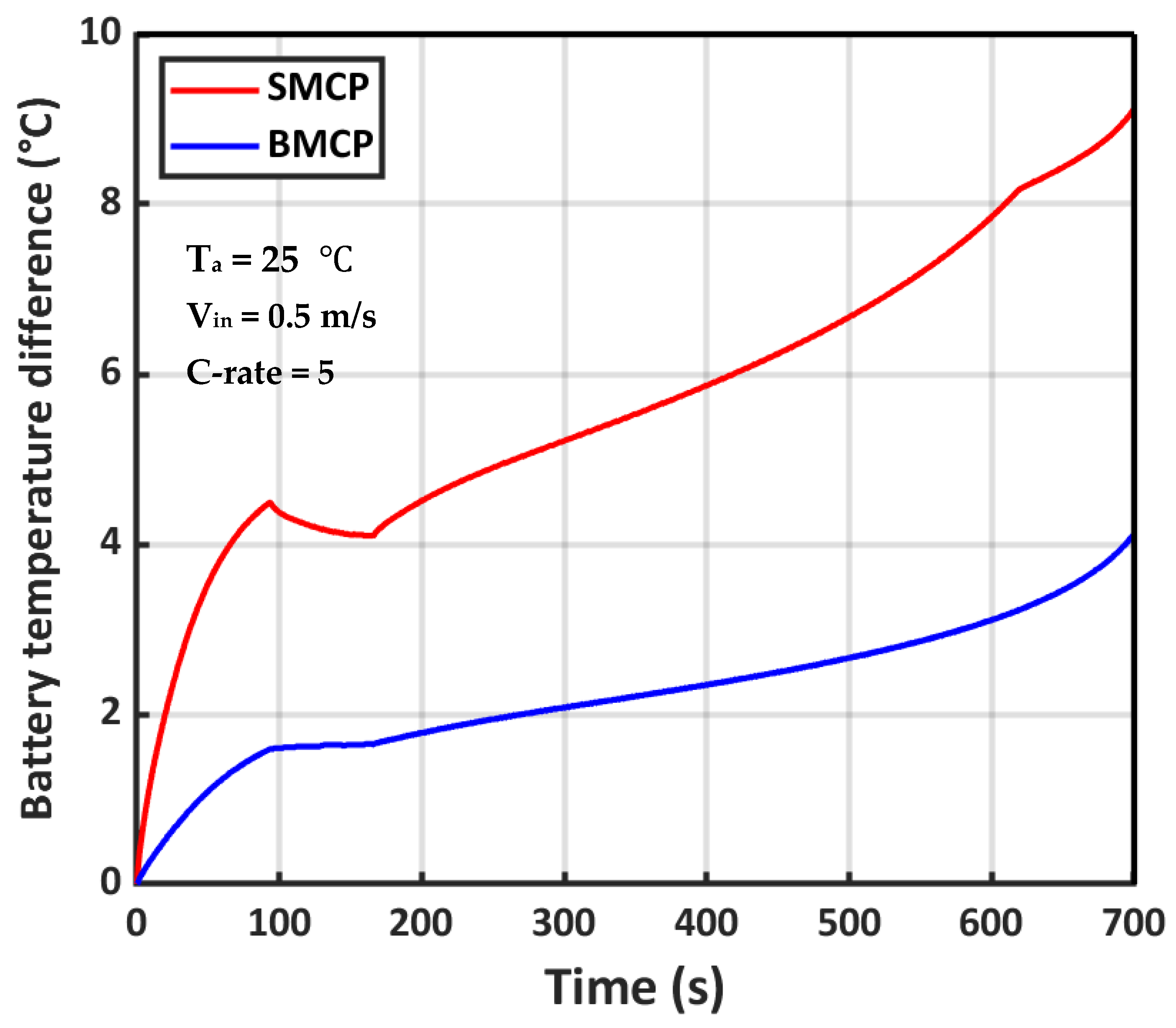
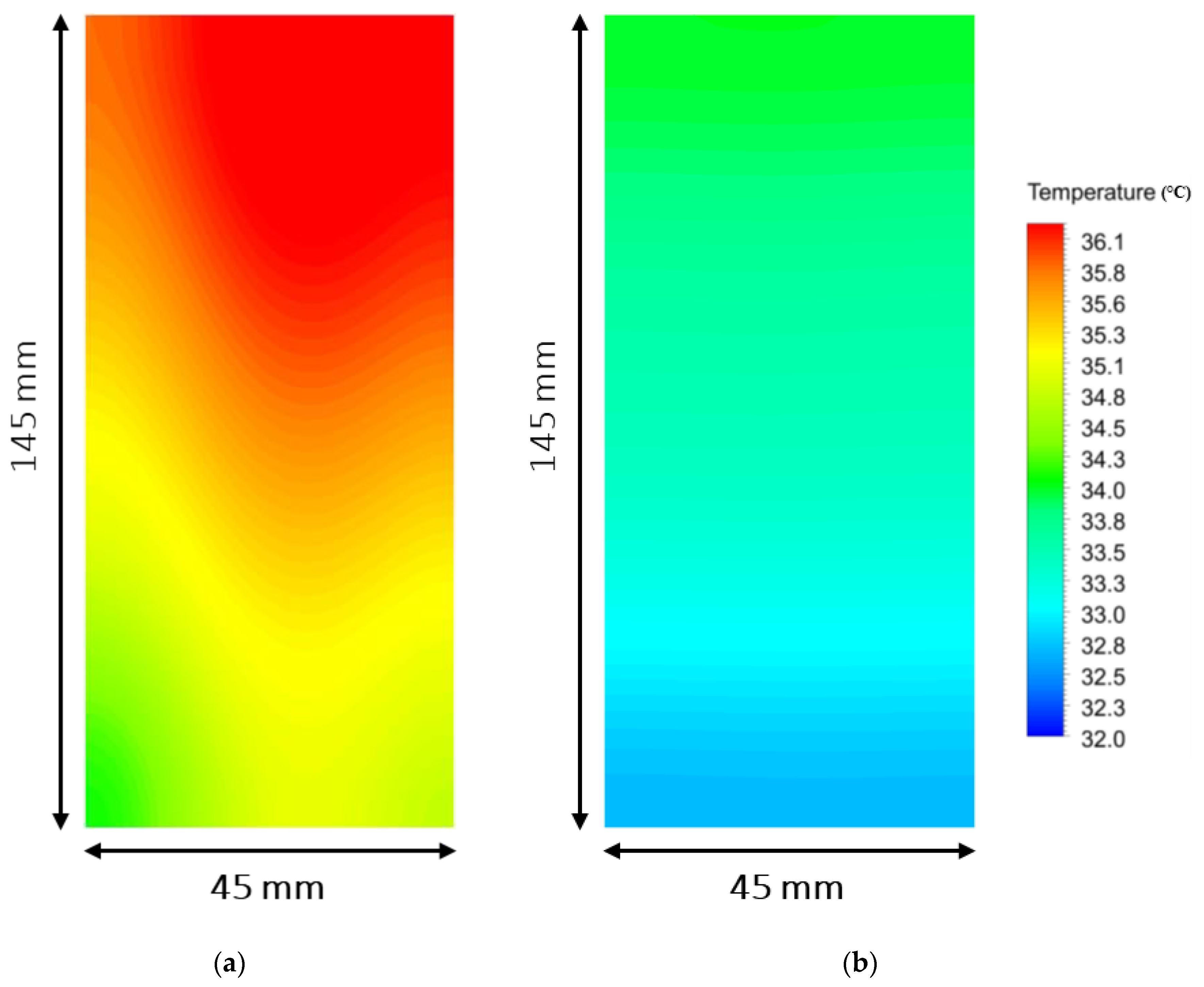
5.1. Performance Characteristics of Enhanced BTMS

Figure 4 and Figure 5 show the variation of maximum temperature and temperature difference of a battery cell for straight microchannels and branched type during a 5C discharge rate, coolant temperature of 25 °C, inlet velocity of 0.5 m/s, and ambient temperature of 25 °C. Both considered parameters experienced a lower value in the branched microchannel cold plate. In the straight microchannel cold plate, the battery maximum temperature rose sharply within 94 s after the discharge process started, to 30.6 °C, and between 95 s and 165 s, the maximum temperature slightly decreased and after that increased to reach 36.61 °C. Battery cell temperature behavior in the branched microchannel cold plate was different compared to the straight microchannel cold plate, owing to enhanced water flow distribution in critical zones. As shown in Figure 4, the battery maximum temperature starts to increase as the discharge process started, and reached 28.4 °C in 95 s, which is 2.2 °C lower compared to the straight microchannel cold plate. Following, the battery temperature after experiencing a constant temperature between 95 s and 165 s start to increase to attain at 34 °C at the end of discharge. These results show that the maximum temperature of the battery cell reduced by 2.61 °C, which led to the battery cell experiencing better working conditions in BMCP compared with SMCP. In addition, temperature difference variation as another important parameter illustrated in Figure 5. As mentioned before, the maximum temperature difference in the battery cell should remain below 5 °C during battery discharging. As shown in Figure 5, the temperature difference in the SMCP cooling system stayed lower than 5 °C until 267 s after the discharge process was initiated and after, a higher value achieved. However, in the BMCP cooling system, the temperature difference does not reach value higher than 5 °C. The temperature difference at 700 s is 9 °C and 4 °C for SMCP and BMCP, respectively.
Figure 6 depicts the temperature contour of the battery cell for SMCP and BMCP at a 5C discharge rate, 0.5 m/s inlet velocity of coolant, and 25 °C ambient temperature. It can be observed that the temperature contour and temperature distribution are the same with the zone around the inlet port being cold and the outlet being hot. During discharge, as coolant liquid flows inside microchannels, the generated heat inside battery cells is conducted to the coolant liquid and the water bulk temperature increases. As expected, the maximum temperature of water was achieved at the outlet port surface. In similar working conditions, SMCP utilizes four straight microchannels to dissipate generated heat along the length of the battery cell, and, as shown in Figure 6a, owing to the liquid coolant, the temperature increased and as a result, the convection heat transfer coefficient decreased and maximum temperature occurred in the vicinity of the outlets port. To overcome this issue, four straight microchannels branched to increase liquid channels and battery cell surface thermal contact. As illustrated in Figure 6b, the maximum temperature in the battery decreased significantly; meanwhile, a better temperature distribution was achieved compared to SMCP.
One of the important LIB challenges faced by researchers to design a sufficient BTMS is low thermal conductivity causing ununiform temperature distribution inside the battery cell. Figure 7 shows the temperature difference variation for both designed cooling systems at a 5C discharge rate, 25 °C ambient temperature, and specific range of inlet velocity: 0.1 to 1 m/s. It can be seen from Figure 7 that SMCP is not capable of keeping the temperature difference below 5 °C in all inlet velocities during discharge. In 1 m/s, as the best-case, the temperature difference is 9 °C. Obviously, increasing inlet velocity in SMCP has a negligible effect on temperature difference owing to the low thermal conductivity of the battery cell. BMCP, by increasing the thermal contact surface between the battery cell and coolant channels, increases the heat transfer coefficient in the critical zone in which the cell temperature has a significant difference from the inlet port surrounding area. As shown in Figure 7, the temperature difference reduced from 7 °C to 3 °C while the inlet velocity increased to 1 m/s. In addition, proper coolant flow distribution led to higher thermal performance, and increasing inlet velocity from 0.1 m/s to 1 m/s caused a 57% lower temperature difference, while SMCP is able to decrease temperature difference by only 20%.

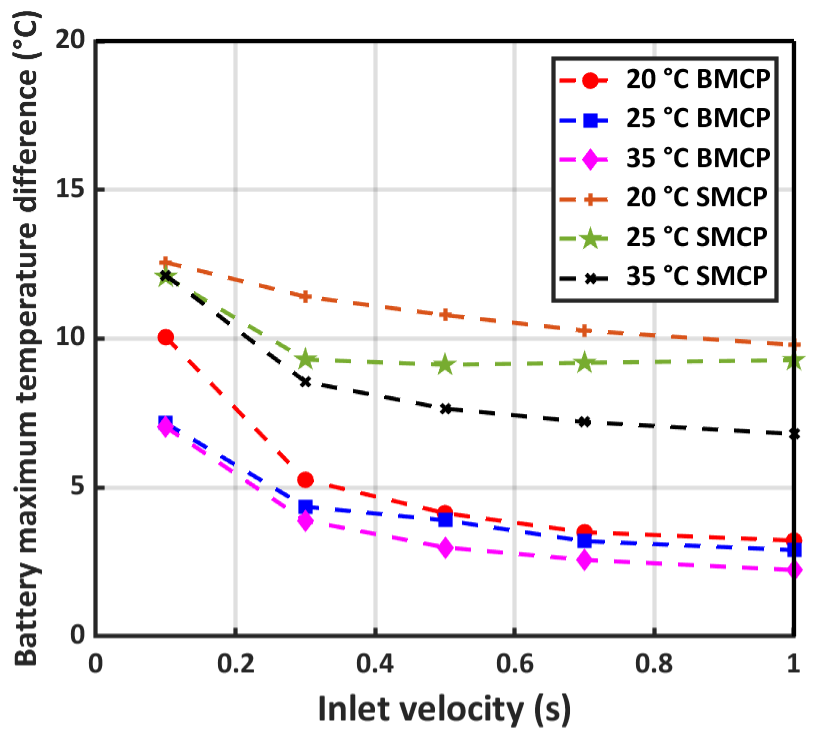
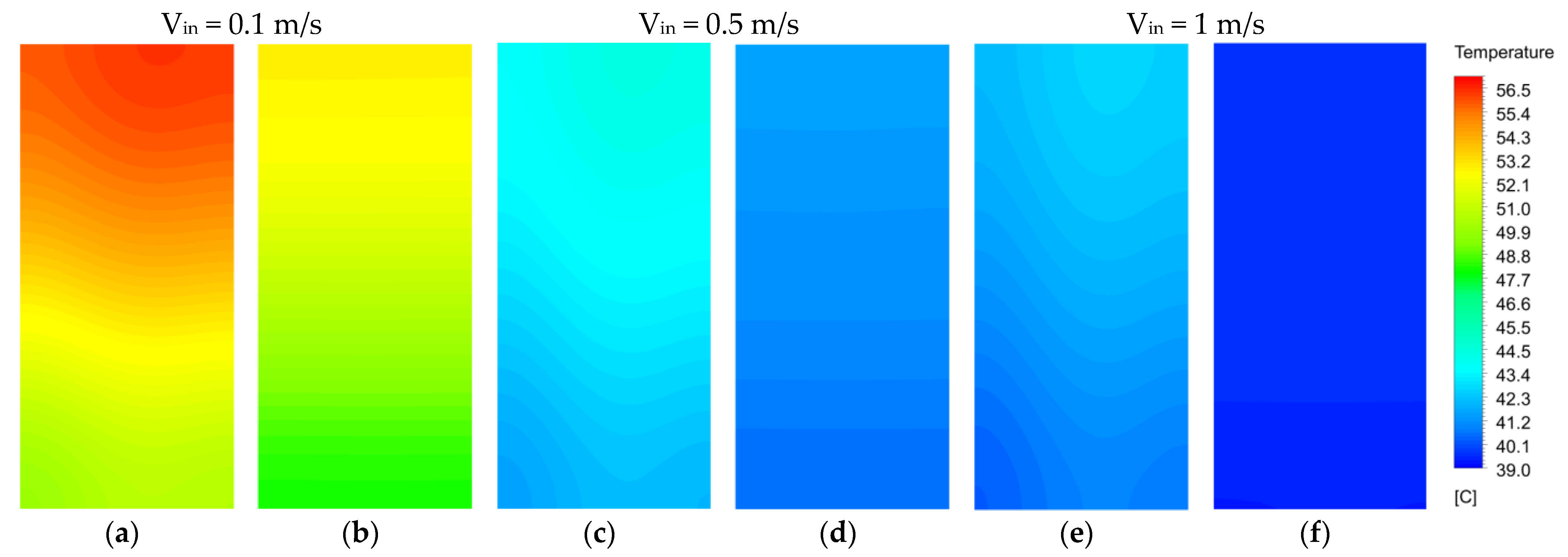
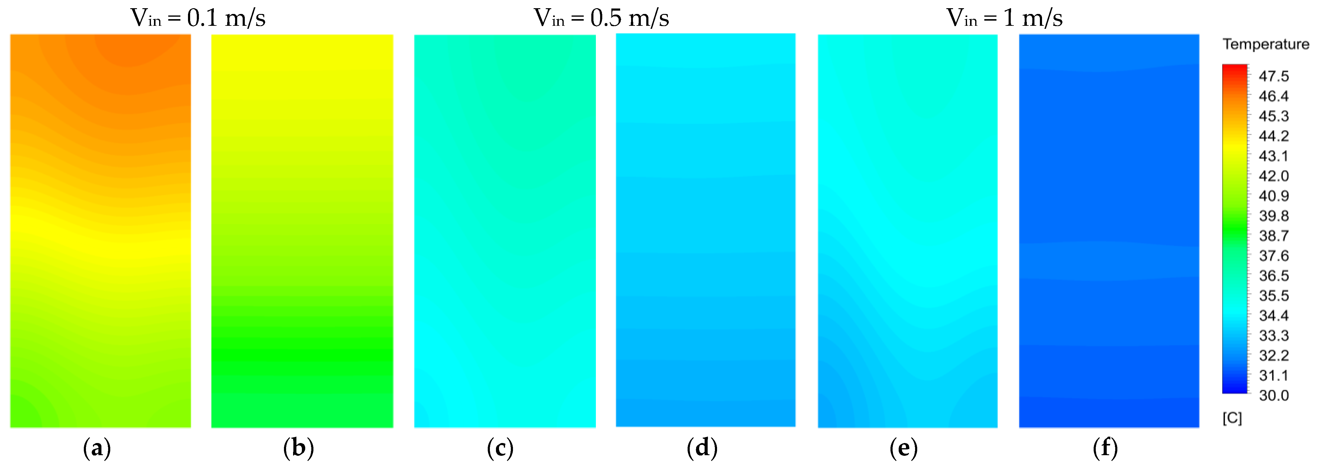
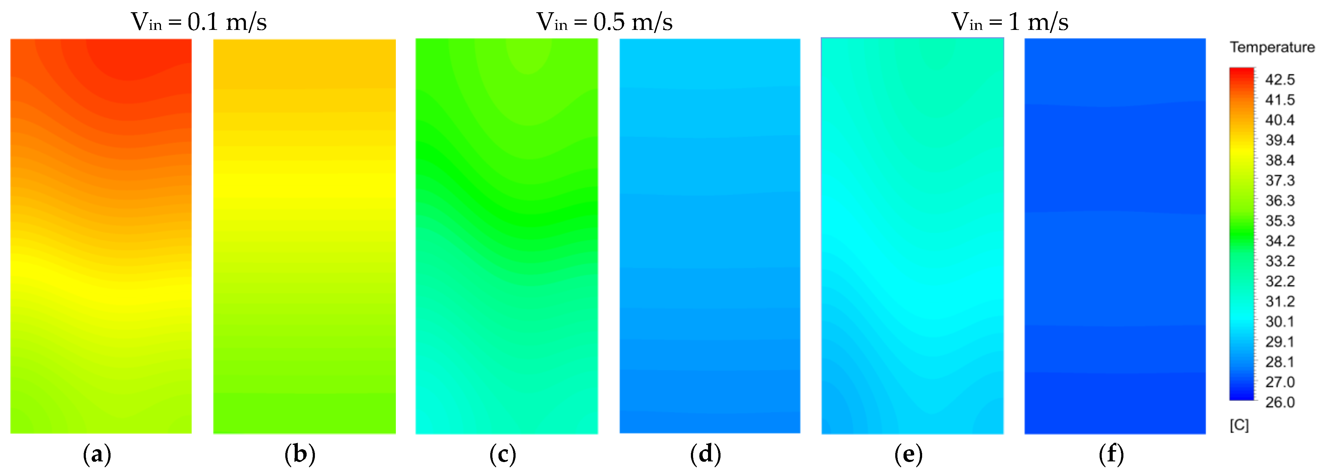
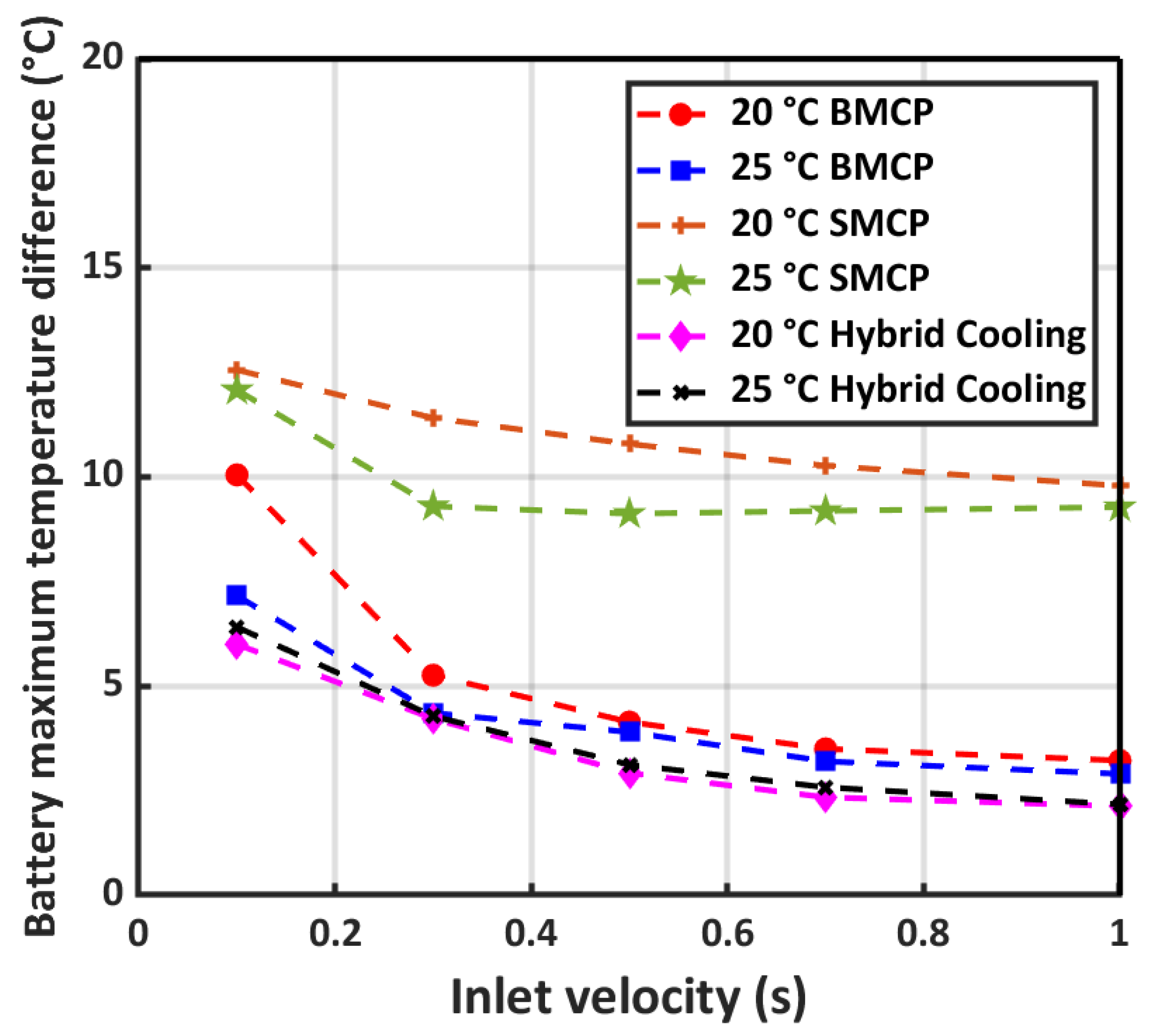
5.2. Effect of Operating Conditions

EVs must be capable of operating in various environmental conditions. In this section, the thermal performance of the designed cooling systems at different ambient temperatures of 20 °C, 25 °C, and 35 °C under a 5C discharge rate and specific range of inlet velocities of 0.1 m/s to 1 m/s is investigated. Figure 8 illustrates the battery maximum temperature variation with respect to inlet velocity in the three mentioned ambient conditions for both proposed cooling systems. Water as the coolant liquid enters the microchannel without precooling and the thermal equilibrium is ambient. Obviously, the maximum temperature decreases as inlet velocity increases in all ambient conditions due to the higher convection heat transfer coefficient. At 0.1 m/s inlet velocity, the maximum temperature difference between BMCP and SMCP is slightly higher than 3 °C, while the inlet velocity reaches a 1 m/s temperature, the difference between the two cooling systems reduced to 2 °C because the heat generation rate in the battery cell remains constant while the heat transfer capacity in both systems increased.
In view of the temperature difference parameters, two critical zones are the inlet port and outlet port, which are the cold and hot areas of battery cells, respectively. Figure 9 shows the temperature difference variation inside the battery cell with respect to inlet velocity at different ambient temperatures of 20 °C, 25 °C, and 35 °C. LIB thermal conductivity in the thickness direction is significantly lower than along the surface. As a result, in a high water temperature, the lower temperature gradient in the thickness direction caused better temperature distribution and the maximum temperature difference decreased. As shown in Figure 9, the maximum temperature difference for both SMCP and BMCP increased when the ambient temperature was reduced from 35 °C to 20 °C. In addition, the inlet velocity effect on temperature differences was investigated. The maximum temperature difference in 0.1 m/s in 20 °C ambient conditions for SMCP and BMSP is 12.56 °C and 10 °C, respectively. By increasing the inlet velocity to 1 m/s, this parameter reduced to 9.79 °C and 3.22 °C, respectively. As is clear, BMSP reduces the temperature difference significantly compared to SMCP in the same working conditions. Meanwhile, increasing velocity led to a reduced temperature difference of 22% and 67.8% in SMCP and BMSP, respectively.
Figure 10, Figure 11 and Figure 12 depicts battery cell temperature contour at different ambient temperatures of 20 °C, 25 °C, and 35 °C under a 5C discharge rate respectively. As can be observed, BMCP has a significant effect on enhancing uniform temperature distribution inside the battery cell. Outlet ports as a critical zone in the battery has the highest temperature in the SMCP cooling system, and, as is shown, BMCP, by enhanced liquid coolant distribution design, reduces the temperature deference in all ambient conditions. In addition, the inlet velocity variation effect is revealed in this figure. By increasing the inlet velocity from 0.1 m/s to 1 m/s in both cooling systems, the temperature distribution become more uniform.

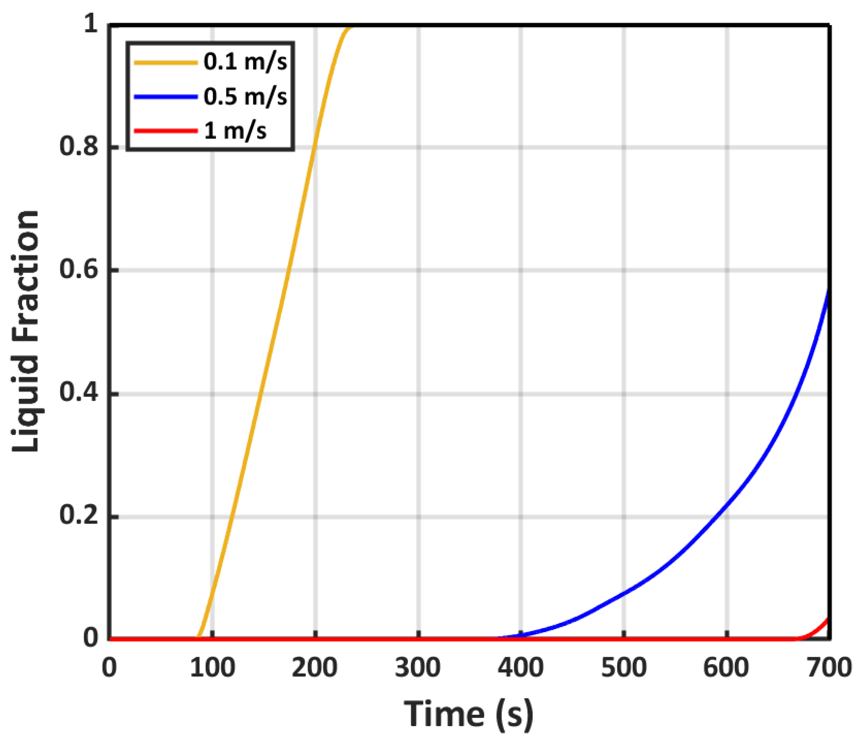
5.3. PCM’s Role in Thermal Performance Enhancement

PCM is able to dissipate a large amount of heat through latent heat without consuming any energy. In addition, PCM can be applied in regions that liquid cooling or other cooling methods cannot deploy. Figure 13 shows the maximum temperature variation with respect to inlet velocity for the hybrid cooling system and BMCP for a 5C discharge rate at ambient temperatures of 20 °C and 25 °C. As can be seen, the maximum temperature in 0.1 m/s and 1 m/s decreases 1.5 °C and 0.93 °C, respectively, at 20 °C ambient conditions. Adding PCM to the cold plate has an insignificant effect at reducing the maximum temperature. Meanwhile, as PCMs are deployed in regions where temperature distribution is ununiform, the temperature difference experienced better conditions compared to BMCP. Figure 14 illustrates the temperature difference inside the battery for BMCP and hybrid cooling with respect to inlet velocity. Temperature difference at 20 °C and 0.1 m/s inlet velocity is 10.5 °C and 6 °C for BMCP and hybrid cooling, respectively. Increasing inlet velocity led to higher heat transfer capacity by the liquid microchannel and the PCM plays little role in heat dissipation and a portion of PCM remains unmelted. Figure 15 depicts the liquid fraction of PCM for various inlet velocities (0.1 m/s, 0.5 m/s, and 1 m/s) and an ambient condition of 20 °C. At 0.1 m/s, PCM fully melted in 240 s and after that, just the liquid cooling system performed as the heat dissipation system. Nevertheless, at 0.5 m/s and 1 m/s, 43% and 97% of PCM remained unmelted. These results revealed that the optimum mass flow rate of cooling liquid can improve hybrid cooling system performance to reach the highest value.

6. Conclusions

In this study, three cooling systems were proposed to dissipate the generated heat from a 7 Ah LIB pouch cell. The first system consists of a cold plate and straight microchannel (SMCP), the second one utilizes a novel branched microchannels cold plate (BMCP) to achieve the best flow distribution strategy. The last system adds PCM to the cold plate as a passive cooling system. Numerical simulations were performed under three ambient conditions: 20 °C, 25 °C, and 35 °C, for a wide range of inlet velocities (0.1 m/s, 0.3 m/s, 0.5 m/s, 0.7 m/s, and 1 m/s), and a discharge rate of 5C.
Results showed that SMCP was not able to maintain the maximum temperature of the battery cell below 50 °C at low inlet velocity. So, a higher rate of mass flow rate is required, which consumes large amount of energy. In addition, in most situations, SMCP cannot provide a proper temperature distribution inside the battery cell.
Increasing the number of microchannels or designing various flow paths like serpentine, zig-zag and etc., was deployed in many studies to decrease the battery maximum temperature. These conventional solutions lead to a lower temperature of the battery cell, while it required higher pumping power, and a higher mass of coolant fluid. However, in this study, branched microchannels only focus on increasing the heat transfer rate in critical areas of the battery cell. Results of BMCP revealed that the proposed path of coolant flow rate, which increased thermal contact with the battery cell critical area, reduced the maximum temperature difference from 10.7 °C to 4 °C, which is in acceptable range. In addition, the maximum temperature decreased by 4.12 °C at a 20 °C ambient temperature and 0.5 m/s inlet velocity. By increasing inlet velocity, the maximum temperature decreases as an obvious result. However, owing to the low thermal conductivity of the battery cell, the rate of decrease in temperature for SMCP was lower than for BMCP with an effective water distribution design.
Finally, to achieve the best thermal performance of the designed BTMS, PCM as a passive cooling system added to BMCP. PCM was only added to special zones and the surrounding microchannel outlet port, which are the most critical zones with the highest battery temperature, to provide a better uniform temperature distribution without consuming energy. The hybrid cooling system decreased the maximum temperature of the battery cell by 1.57 °C and the maximum temperature difference was 4 °C compared to BMCP. Increasing inlet velocity reduced PCM’s role in heat dissipation and an optimum flow rate of coolant was required to reach the best performance of BTMS.
A hybrid cooling system can enhance BTMS thermal performance mainly by deploying passive cooling methods which do not consume energy. However, adding PCM to the cooling system should be restricted with respect to BTMS total weight. The mass of PCM in the current study can be optimized in future works to meet the best thermal performance with optimized weight of PCM.

Author Contributions

Data curation, investigation, writing—original draft, M.R.; conceptualization, data curation, investigation, validation, writing—review and editing, A.G.; writing—original draft, investigation, S.S.; supervision, methodology, resources, validation, writing—review and editing, A.M.A.; supervision, writing—review and editing, J.K. All authors have read and agreed to the published version of the manuscript.

Funding

This research received no external funding.

Data Availability Statement

Not applicable.

Conflicts of Interest

The authors declare no conflict of interest.

References

  1. Zhao, Y.; Zou, B.; Zhang, T.; Jiang, Z.; Ding, J.; Ding, Y. A Comprehensive Review of Composite Phase Change Material Based Thermal Management System for Lithium-Ion Batteries. Renew. Sustain. Energy Rev. 2022, 167, 112667. [Google Scholar] [CrossRef]
  2. Li, W.; Zhou, Y.; Zhang, H.; Tang, X. A Review on Battery Thermal Management for New Energy Vehicles. Energies 2023, 16, 4845. [Google Scholar] [CrossRef]
  3. Belgibayeva, A.; Rakhmetova, A.; Rakhatkyzy, M.; Kairova, M.; Mukushev, I.; Issatayev, N.; Kalimuldina, G.; Nurpeissova, A.; Sun, Y.K.; Bakenov, Z. Lithium-Ion Batteries for Low-Temperature Applications: Limiting Factors and Solutions. J. Power Sources 2023, 557, 232550. [Google Scholar] [CrossRef]
  4. Su, X.; Xu, Y.; Wu, Y.; Li, H.; Yang, J.; Liao, Y.; Qu, R.; Zhang, Z. Liquid Electrolytes for Low-Temperature Lithium Batteries: Main Limitations, Current Advances, and Future Perspectives. Energy Storage Mater. 2023, 56, 642–663. [Google Scholar] [CrossRef]
  5. Liu, C.; Wen, X.; Zhong, J.; Liu, W.; Chen, J.; Zhang, J.; Wang, Z.; Liao, Q. Characterization of Aging Mechanisms and State of Health for Second-Life 21700 Ternary Lithium-Ion Battery. J. Energy Storage 2022, 55, 105511. [Google Scholar] [CrossRef]
  6. Mehrenjani, J.R.; Gharehghani, A.; Nasrabadi, A.M.; Moghimi, M. Design, Modeling and Optimization of a Renewable-Based System for Power Generation and Hydrogen Production. Int. J. Hydrogen Energy 2022, 47, 14225–14242. [Google Scholar] [CrossRef]
  7. Kim, J.; Oh, J.; Lee, H. Review on Battery Thermal Management System for Electric Vehicles. Appl. Therm. Eng. 2019, 149, 192–212. [Google Scholar] [CrossRef]
  8. Wang, Y.; Yu, Y.; Jing, Z.; Wang, C.; Zhou, G.; Zhao, W. Thermal Performance of Lithium-Ion Batteries Applying Forced Air Cooling with an Improved Aluminium Foam Heat Sink Design. Int. J. Heat Mass. Transf. 2021, 167, 120827. [Google Scholar] [CrossRef]
  9. Andwari, A.M.; Aziz, A.A.; Muhamad Said, M.F.; Latiff, Z.A.; Ghanaati, A. Influence of Hot Burned Gas Utilization on The Exhaust Emission Characteristics of A Controlled Auto-Ignition Two-Stroke Cycle Engine. Int. J. Automot. Mechanical. Eng. 2015, 11, 2396–2404. [Google Scholar] [CrossRef]
  10. Moradi, J.; Gharehghani, A.; Mirsalim, M. Numerical Comparison of Combustion Characteristics and Cost between Hydrogen, Oxygen and Their Combinations Addition on Natural Gas Fueled HCCI Engine. Energy Convers. Manag. 2020, 222, 113254. [Google Scholar] [CrossRef]
  11. Gharehghani, A.; Kakoee, A.; Andwari, A.M.; Megaritis, T.; Pesyridis, A. Numerical investigation of an RCCI engine fueled with natural gas/dimethyl-ether in various injection strategies. Energies 2021, 14, 1638. [Google Scholar] [CrossRef]
  12. Moradi, J.; Gharehghani, A.; Mirsalim, M. Numerical Investigation on the Effect of Oxygen in Combustion Characteristics and to Extend Low Load Operating Range of a Natural-Gas HCCI Engine. Appl. Energy 2020, 276, 115516. [Google Scholar] [CrossRef]
  13. Mahmoudzadeh Andwari, A.; Aziz, A.A.; Muhamad Said, M.F.; Abdul Latiff, Z. Controlled Auto-Ignition Combustion in a Two-Stroke Cycle Engine Using Hot Burned Gases. Appl. Mech. Mater. 2013, 388, 201–205. [Google Scholar] [CrossRef]
  14. Ahmadi, S.; Gharehghani, A.; Soltani, M.M.; Fakhari, A.H. Design and Evaluation of Renewable Energies-Based Multi-Generation System for Hydrogen Production, Freshwater and Cooling. Renew. Energy 2022, 198, 916–935. [Google Scholar] [CrossRef]
  15. Chen, K.; Chen, Y.; Li, Z.; Yuan, F.; Wang, S. Design of the Cell Spacings of Battery Pack in Parallel Air-Cooled Battery Thermal Management System. Int. J. Heat Mass Transf. 2018, 127, 393–401. [Google Scholar] [CrossRef]
  16. Wang, M.; Hung, T.C.; Xi, H. Numerical Study on Performance Enhancement of the Air-Cooled Battery Thermal Management System by Adding Parallel Plates. Energies 2021, 14, 3096. [Google Scholar] [CrossRef]
  17. Widyantara, R.D.; Naufal, M.A.; Sambegoro, P.L.; Nurprasetio, I.P.; Triawan, F.; Djamari, D.W.; Bayu, A.; Nandiyanto, D.; Budiman, B.A.; Aziz, M. Low-cost air-cooling system optimization on battery pack of Electric Vehicle. Energies 2021, 14, 7954. [Google Scholar] [CrossRef]
  18. Le, Q.; Shi, Q.; Liu, Q.; Yao, X.; Ju, X.; Xu, C. Numerical Investigation on Manifold Immersion Cooling Scheme for Lithium Ion Battery Thermal Management Application. Int. J. Heat Mass Transf. 2022, 190, 122750. [Google Scholar] [CrossRef]
  19. Zhao, D.; Lei, Z.; An, C. Research on Battery Thermal Management System Based on Liquid Cooling Plate with Honeycomb-like Flow Channel. Appl. Therm. Eng. 2022, 218, 119324. [Google Scholar] [CrossRef]
  20. Wang, H.; Tao, T.; Xu, J.; Mei, X.; Liu, X.; Gou, P. Cooling Capacity of a Novel Modular Liquid-Cooled Battery Thermal Management System for Cylindrical Lithium Ion Batteries. Appl. Therm. Eng. 2020, 178, 115591. [Google Scholar] [CrossRef]
  21. Li, P.; Zhao, J.; Zhou, S.; Duan, J.; Li, X.; Zhang, H.; Yuan, J. Design and Optimization of a Liquid Cooling Thermal Management System with Flow Distributors and Spiral Channel Cooling Plates for Lithium-Ion Batteries. Energies 2023, 16, 2196. [Google Scholar] [CrossRef]
  22. Magnini, M.; Thome, J.R. A CFD Study of the Parameters Influencing Heat Transfer in Microchannel Slug Flow Boiling. Int. J. Therm. Sci. 2016, 110, 119–136. [Google Scholar] [CrossRef]
  23. Li, H.; Hrnjak, P. Flow Visualization of R1234ze(E) in a 0.643 mm Microchannel Tube. Int. J. Heat Mass Transf. 2019, 136, 950–961. [Google Scholar] [CrossRef]
  24. Wang, X.; Li, B.; Huang, K.; Yan, Y.; Stone, I.; Worrall, S. Experimental Investigation on End Winding Thermal Management with Oil Spray in Electric Vehicles. Case Stud. Therm. Eng. 2022, 35, 102082. [Google Scholar] [CrossRef]
  25. Jayarajan, S.A.; Azimov, U. CFD Modeling and Thermal Analysis of a Cold Plate Design with a Zig-Zag Serpentine Flow Pattern for Li-Ion Batteries by Dissipation. Energies 2023, 16, 5243. [Google Scholar] [CrossRef]
  26. Wei, L.; Zou, Y.; Cao, F.; Ma, Z.; Lu, Z.; Jin, L. An Optimization Study on the Operating Parameters of Liquid Cold Plate for Battery Thermal Management of Electric Vehicles. Energies 2022, 15, 9180. [Google Scholar] [CrossRef]
  27. Dong, J.; Lu, X.; Sun, Y.; Mitin, V.; Xu, H.; Kong, W. Design of Battery Thermal Management System with Considering the Longitudinal and Transverse Temperature Difference. Energies 2022, 15, 7448. [Google Scholar] [CrossRef]
  28. Lee, P.S.; Garimella, S.V. Saturated Flow Boiling Heat Transfer and Pressure Drop in Silicon Microchannel Arrays. Int. J. Heat Mass Transf. 2008, 51, 789–806. [Google Scholar] [CrossRef]
  29. Li, H.; Hrnjak, P. Heat Transfer and Pressure Drop of R32 Evaporating in One Pass Microchannel Tube with Parallel Channels. Int. J. Heat Mass Transf. 2018, 127, 526–540. [Google Scholar] [CrossRef]
  30. Lin, R.; Xie, J.; Liang, R.; Li, X.; Zhang, G.; Li, B. Experiments and Simulation on the Performance of a Liquid-Cooling Thermal Management System Including Composite Silica Gel and Mini-Channel Cold Plates for a Battery Module. Energies 2022, 15, 9103. [Google Scholar] [CrossRef]
  31. Worwood, D.; Marco, J.; Kellner, Q.; Hosseinzadeh, E.; McGlen, R.; Mullen, D.; Lynn, K.; Greenwood, D. Experimental Analysis of a Novel Cooling Material for Large Format Automotive Lithium-Ion Cells. Energies 2019, 12, 1251. [Google Scholar] [CrossRef]
  32. Zhao, C.; Zhang, B.; Zheng, Y.; Huang, S.; Yan, T. Hybrid battery thermal management system in Electrical Vehicles: A Review. Energies 2020, 13, 6257. [Google Scholar] [CrossRef]
  33. Huang, Y.H.; Cheng, W.L.; Zhao, R. Thermal Management of Li-Ion Battery Pack with the Application of Flexible Form-Stable Composite Phase Change Materials. Energy Convers. Manag. 2019, 182, 9–20. [Google Scholar] [CrossRef]
  34. Choudhari, V.G.; Dhoble, A.S.; Panchal, S.; Fowler, M.; Fraser, R. Numerical Investigation on Thermal Behaviour of 5 × 5 Cell Configured Battery Pack Using Phase Change Material and Fin Structure Layout. J. Energy Storage 2021, 43, 103234. [Google Scholar] [CrossRef]
  35. Rabiei, M.; Gharehghani, A.; Andwari, A.M. Enhancement of Battery Thermal Management System Using a Novel Structure of Hybrid Liquid Cold Plate. Appl. Therm. Eng. 2023, 232, 121051. [Google Scholar] [CrossRef]
  36. Ki, S.; Lee, J.; Kim, S.; Seong, J.; Shim, J.; Oh, S.; Cho, S.; Bang, S.; Seo, D.; Kim, J.; et al. An Energy-Efficient Battery Thermal Management System Incorporating a Porous Metal-Based Multiscale Flow Manifold. Energy Convers. Manag. 2022, 269, 116147. [Google Scholar] [CrossRef]
  37. Weng, J.; He, Y.; Ouyang, D.; Yang, X.; Zhang, G.; Wang, J. Thermal Performance of PCM and Branch-Structured Fins for Cylindrical Power Battery in a High-Temperature Environment. Energy Convers. Manag. 2019, 200, 112106. [Google Scholar] [CrossRef]
  38. Liu, Y.; Zheng, R.; Li, J. High latent heat phase change materials (PCMs) with low melting temperature for thermal management and storage of electronic devices and power batteries: Critical review. Renew. Sustain. Energy Rev. 2022, 168, 112783. [Google Scholar] [CrossRef]
  39. Kalkan, O.; Celen, A.; Bakirci, K. Multi-Objective Optimization of a Mini Channeled Cold Plate for Using Thermal Management of a Li-Ion Battery. Energy 2022, 251, 123949. [Google Scholar] [CrossRef]
  40. Mehrabi-Kermani, M.; Houshfar, E.; Ashjaee, M. A Novel Hybrid Thermal Management for Li-Ion Batteries Using Phase Change Materials Embedded in Copper Foams Combined with Forced-Air Convection. Int. J. Therm. Sci. 2019, 141, 47–61. [Google Scholar] [CrossRef]
  41. Zhang, W.; Liang, Z.; Ling, G.; Huang, L. Influence of Phase Change Material Dosage on the Heat Dissipation Performance of the Battery Thermal Management System. J. Energy Storage 2021, 41, 102849. [Google Scholar] [CrossRef]
  42. Lamrani, B.; Lebrouhi, B.E.; Khattari, Y.; Kousksou, T. A Simplified Thermal Model for a Lithium-Ion Battery Pack with Phase Change Material Thermal Management System. J. Energy Storage 2021, 44, 103377. [Google Scholar] [CrossRef]
  43. Ding, Y.; Wei, M.; Liu, R. Channel Parameters for the Temperature Distribution of a Battery Thermal Management System with Liquid Cooling. Appl. Therm. Eng. 2021, 186, 116494. [Google Scholar] [CrossRef]
  44. Chen, S.; Bao, N.; Garg, A.; Peng, X.; Gao, L. A Fast Charging–Cooling Coupled Scheduling Method for a Liquid Cooling-Based Thermal Management System for Lithium-Ion Batteries. Engineering 2021, 7, 1165–1176. [Google Scholar] [CrossRef]
  45. Qi, W.; Huang, W.; Niu, J.; Chen, F.; Chen, B.; Chen, Y. Thermal Management of Power Battery Based on Flexible Swiss Roll Type Liquid Cooling Micro-Channel. Appl. Therm. Eng. 2023, 219, 119491. [Google Scholar] [CrossRef]
  46. Li, M.; Ma, S.; Jin, H.; Wang, R.; Jiang, Y. Performance Analysis of Liquid Cooling Battery Thermal Management System in Different Cooling Cases. J. Energy Storage 2023, 72, 108651. [Google Scholar] [CrossRef]
  47. Bernardi, D.; Pawlikowski, E.; Newman, J. General Energy Balance for Battery Systems. Electrochem. Soc. Ext. Abstr. 1984, 132, 164–165. [Google Scholar] [CrossRef]
  48. Fathabadi, H. A Novel Design Including Cooling Media for Lithium-Ion Batteries Pack Used in Hybrid and Electric Vehicles. J. Power Sources 2014, 245, 495–500. [Google Scholar] [CrossRef]
  49. Gharehghani, A.; Gholami, J.; Shamsizadeh, P.; Mehranfar, S. Effect Analysis on Performance Improvement of Battery Thermal Management in Cold Weather. J. Energy Storage 2022, 45, 103728. [Google Scholar] [CrossRef]
  50. Lin, C.; Chen, K.; Sun, F.; Tang, P.; Zhao, H. Research on Thermo-Physical Properties Identification and Thermal Analysis of EV Li-Ion Battery. In Proceedings of the 5th IEEE Vehicle Power and Propulsion Conference VPPC, Dearborn, MI, USA, 7–10 September 2009; pp. 1643–1648. [Google Scholar] [CrossRef]
  51. Fan, L.; Khodadadi, J.M.; Pesaran, A.A. A Parametric Study on Thermal Management of an Air-Cooled Lithium-Ion Battery Module for Plug-in Hybrid Electric Vehicles. J. Power Sources 2013, 238, 301–312. [Google Scholar] [CrossRef]
  52. Shmueli, H.; Ziskind, G.; Letan, R. Melting in a Vertical Cylindrical Tube: Numerical Investigation and Comparison with Experiments. Int. J. Heat Mass Transf. 2010, 53, 4082–4091. [Google Scholar] [CrossRef]
Figure 1. (a) Schematic of battery module, cold plates, and location of microchannels, (b) SMCP, (c) BMSP, (d) hybrid PCM and BMCP cooling.
Energies 16 06238 g001aEnergies 16 06238 g001b
Figure 2. Grid independency test during 5C discharge rate.
Energies 16 06238 g002
Figure 3. (a) Comparison of mean temperature rise [50], (b) comparison between the numerical results and the experimental results of Shmueli et al. [52].
Energies 16 06238 g003
Figure 4. Battery cell maximum temperature variation for SMCP and BMCP at a 5C discharge rate.
Energies 16 06238 g004
Figure 5. Battery cell temperature difference for SMCP and BMCP in 5C discharge rate.
Energies 16 06238 g005
Figure 6. Battery cell temperature contour at a 5C discharge rate, 0.5 m/s inlet velocity, (a) SMCP, (b) BMCP.
Energies 16 06238 g006
Figure 7. Temperature difference variation in 5C discharge rate.
Energies 16 06238 g007
Figure 8. Battery maximum cell variation with respect to inlet velocity at a 5C discharge rate for SMCP and BMCP cooling systems.
Energies 16 06238 g008
Figure 9. Battery maximum temperature difference with respect to velocity at a 5C discharge rate for SMCP and BMCP cooling systems.
Energies 16 06238 g009
Figure 10. Temperature contour in 35 °C ambient conditions, (a,c,e) SMCP, (b,d,f) BMCP.
Energies 16 06238 g010
Figure 11. Temperature contour in 25 °C ambient conditions, (a,c,e) SMCP, (b,d,f) BMCP.
Energies 16 06238 g011
Figure 12. Temperature contour in 20 °C ambient conditions, (a,c,e) SMCP, (b,d,f) BMCP.
Energies 16 06238 g012
Figure 13. Battery maximum temperature variation with respect to inlet velocity.
Energies 16 06238 g013
Figure 14. Battery temperature difference variation with respect to inlet velocity.
Energies 16 06238 g014
Figure 15. PCM liquid fraction in various coolant inlet velocities.
Energies 16 06238 g015
Table 1. Comparison between the current study and recent studies around hybrid cooling in lithium-ion batteries.
ResearchRef.YearElements of Cooling SystemBattery TypeC-Rate T m a x   ( K ) T m a x   ( K )
Kermani et al.[40]2019PCM + Copper foamPouchy5C308.94.6
Zhang et al.[41]2021PCMPrismatic5C314.52.5
Lamrani et al.[42]2021PCMCylindrical3C305.1-
Ding et al.[43]2021LiquidPrismatic1C304.24.6
Chen et al.[44]2021Liquid + Cold platePrismatic2C306.50.8
Qi et al.[45]2023Liquid + Mico channelCylindrical3C300.43.3
Li et al.[46]2023Liquid + Cold plate + SMCPPrismatic5C3135
Kalkan et al.[39]2022Liquid + Cold plate + BMCPPrismatic5C303.62.3
Current study--PCM + Liquid + Cold plate + BMCPPrismatic5C308.12
Table 2. Battery cell specifications.
Battery ParameterValue
Size ( mm × mm × mm ) 145 × 45 × 9
Density ( kg / m 3 )2263
Capacity (mAh)7000
Work temperature (°C)10–45
Nominal voltage (V)3.8
Thermal conductivity (W/m.K)43.33/43.331.5 (x/y/z)
Positive electrode material Al
Negative electrode materialCu
Specific heat capacity (J/kg.K)1532.5
Table 3. Cold plate specifications.
Cold Plate ParameterValue
Size ( mm × mm × mm ) 45 × 145 × 3
Density ( kg / m 3 )2719
Thermal conductivity (W/m.K)202
Specific heat capacity (J/kg.K)871
Table 4. Geometrical and thermodynamic specifications of PCM.
Specific Heat
Capacity (J/kg.K)
Dynamic
Viscosity (kg/m s)
Density   ( kg / m 3 ) Latent Heat (kJ/kg)Thermal
Conductivity (W/m.K)
Size ( mm )
Solid2500-8701790.24 2 × 60 × 30
Liquid2500−1.137439 E − 8 T3 + 1.178188 E − 5 T2 − 0.0041113888T + 0.4857203870 @ 299 K781.5 @ 301 K750 @ 343 K1790.15
Table 5. Comparison of SDT inside the battery.
Flow   Rate   ( m 3 / h ) This StudyFan et al. [51]Difference %
10.20.8410.8632.55
20.40.8320.8231.08
30.60.7490.7561.32
40.80.6850.6652.92
Disclaimer/Publisher’s Note: The statements, opinions and data contained in all publications are solely those of the individual author(s) and contributor(s) and not of MDPI and/or the editor(s). MDPI and/or the editor(s) disclaim responsibility for any injury to people or property resulting from any ideas, methods, instructions or products referred to in the content.

