
A Review on AC Voltage Variation Compensators in Low Voltage Distribution Network


Abstract
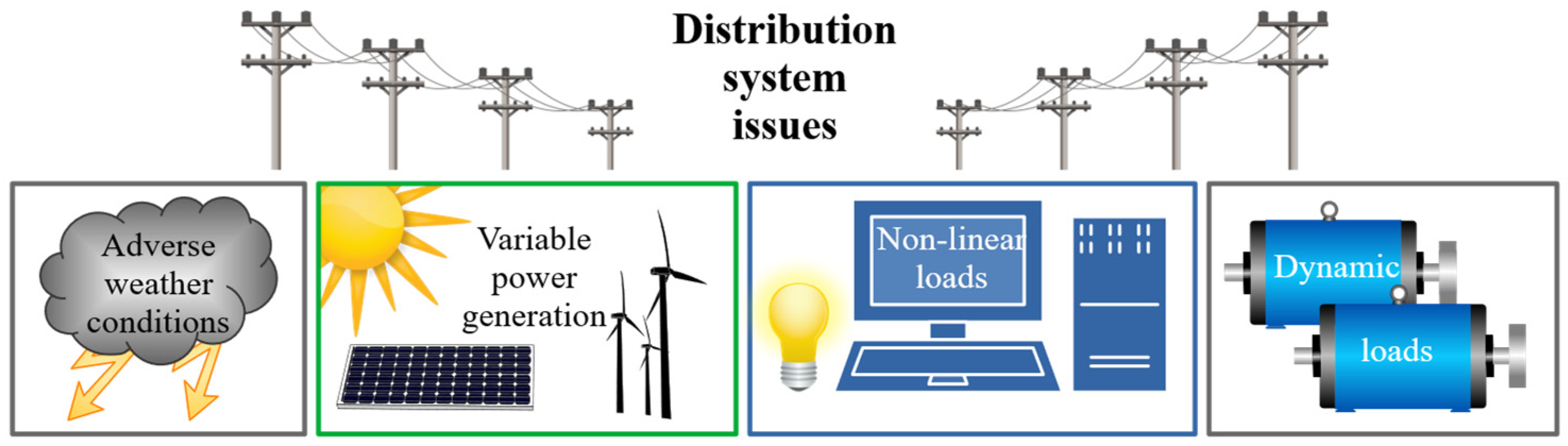
:1. Introduction
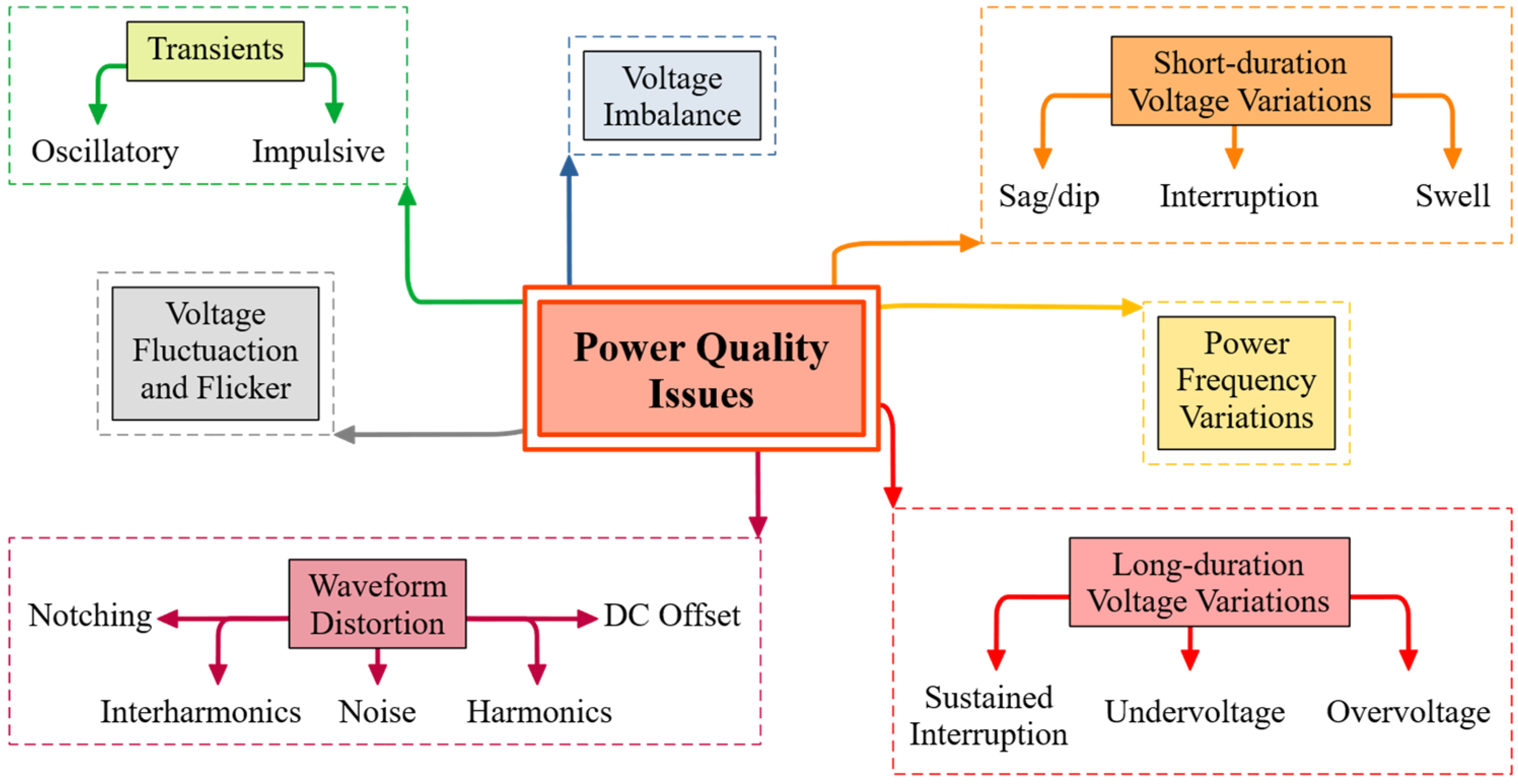
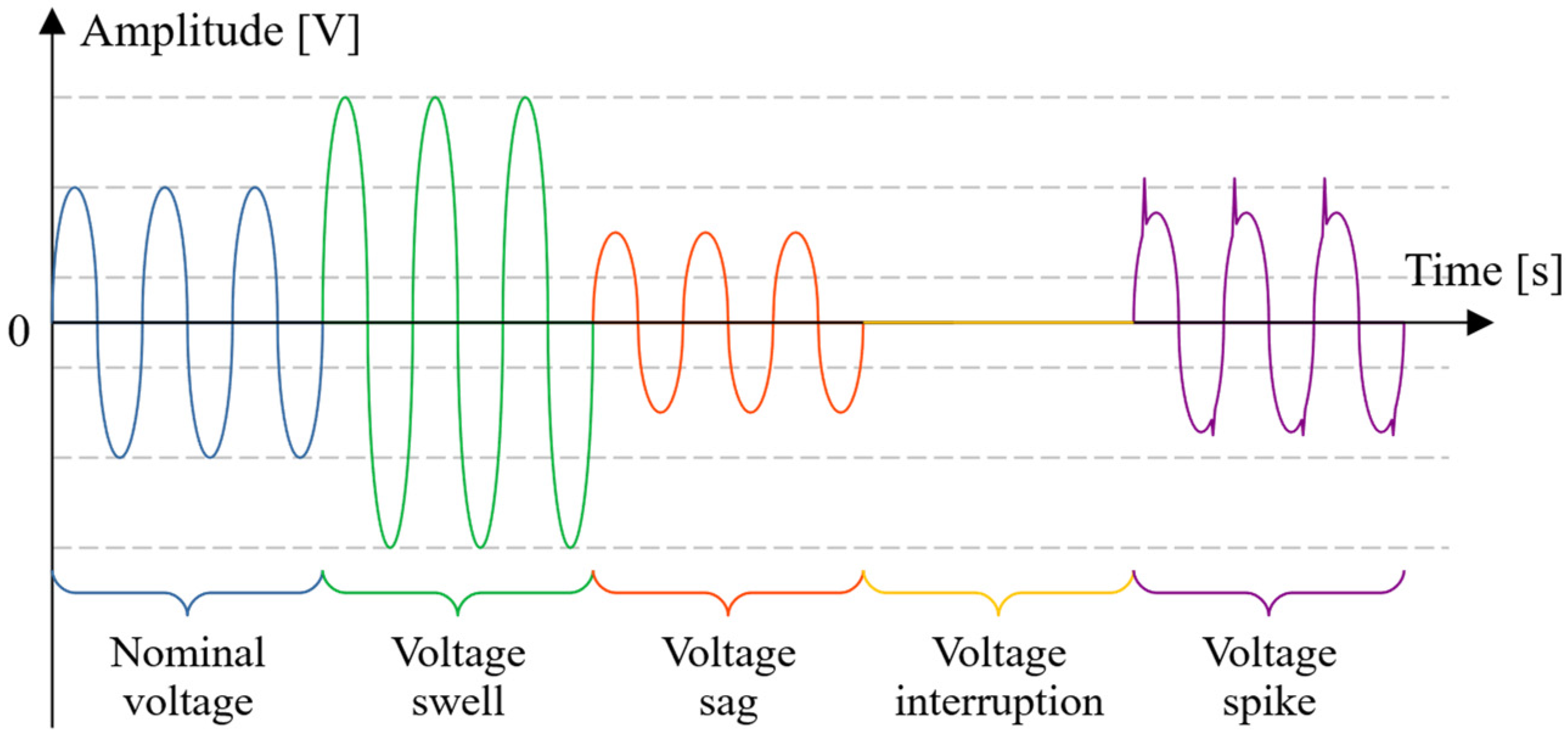
1.1. Classification of Problems Related to the Power Quality
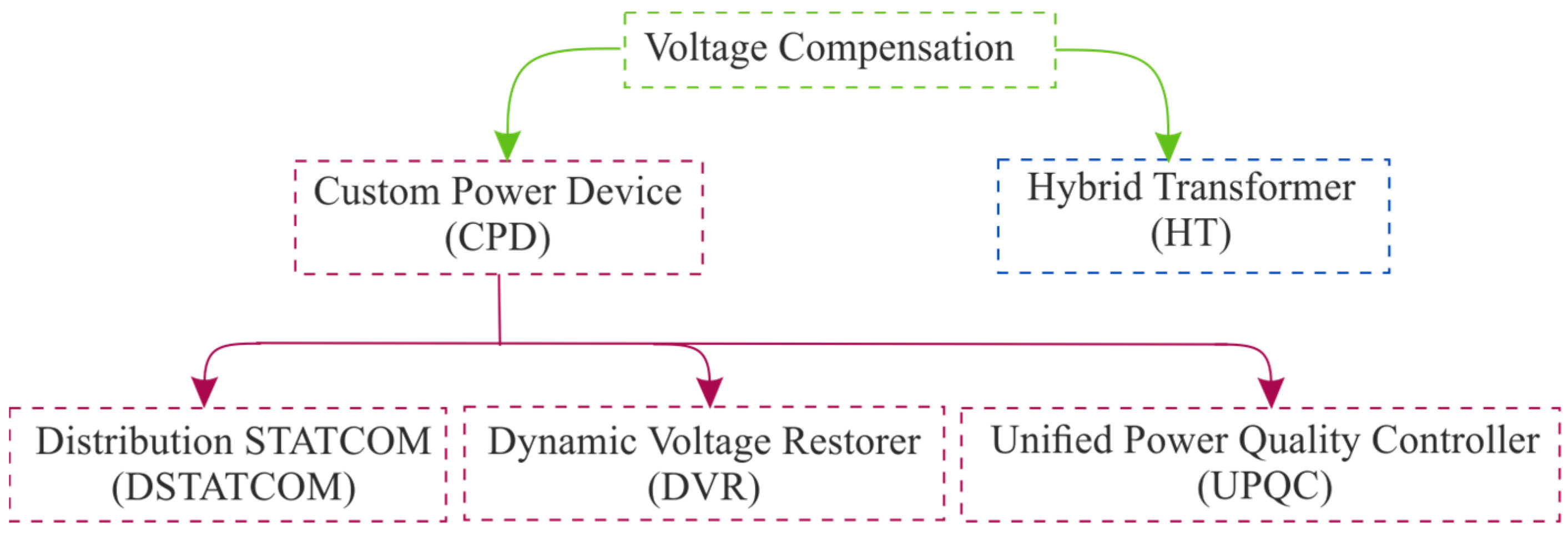
1.2. Disturbance Mitigation in the Distribution Network
1.3. Article Contribution and Structure
2. Topologies of the UPQC and the HT
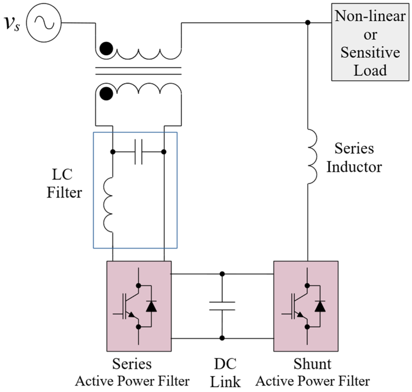
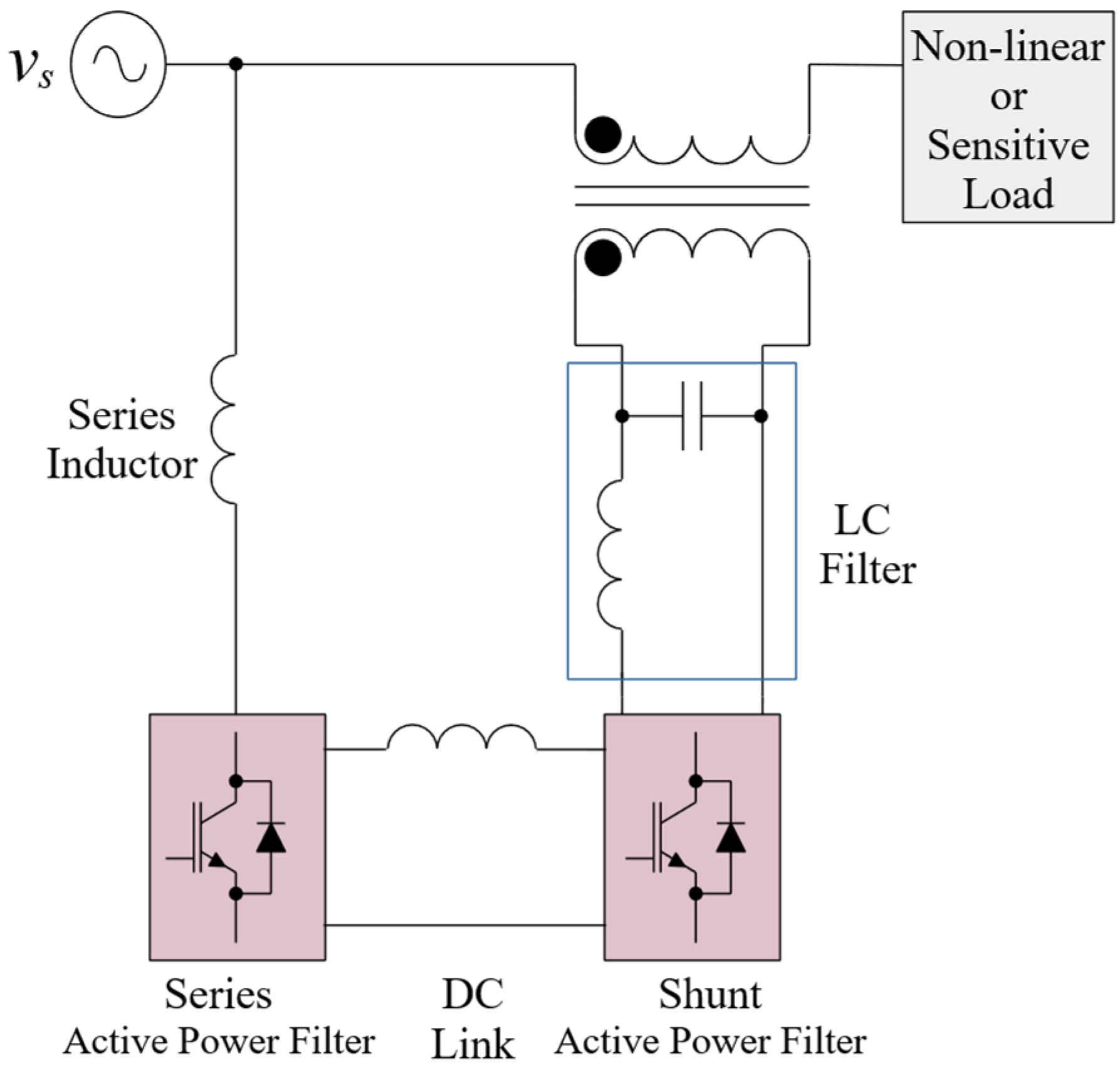
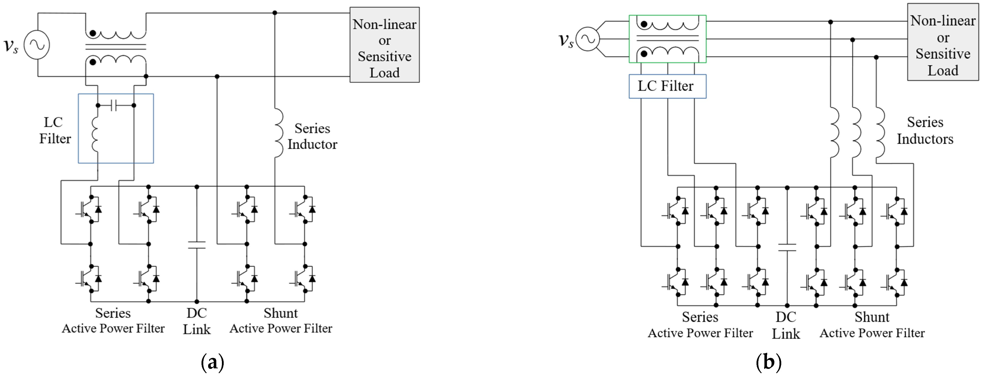
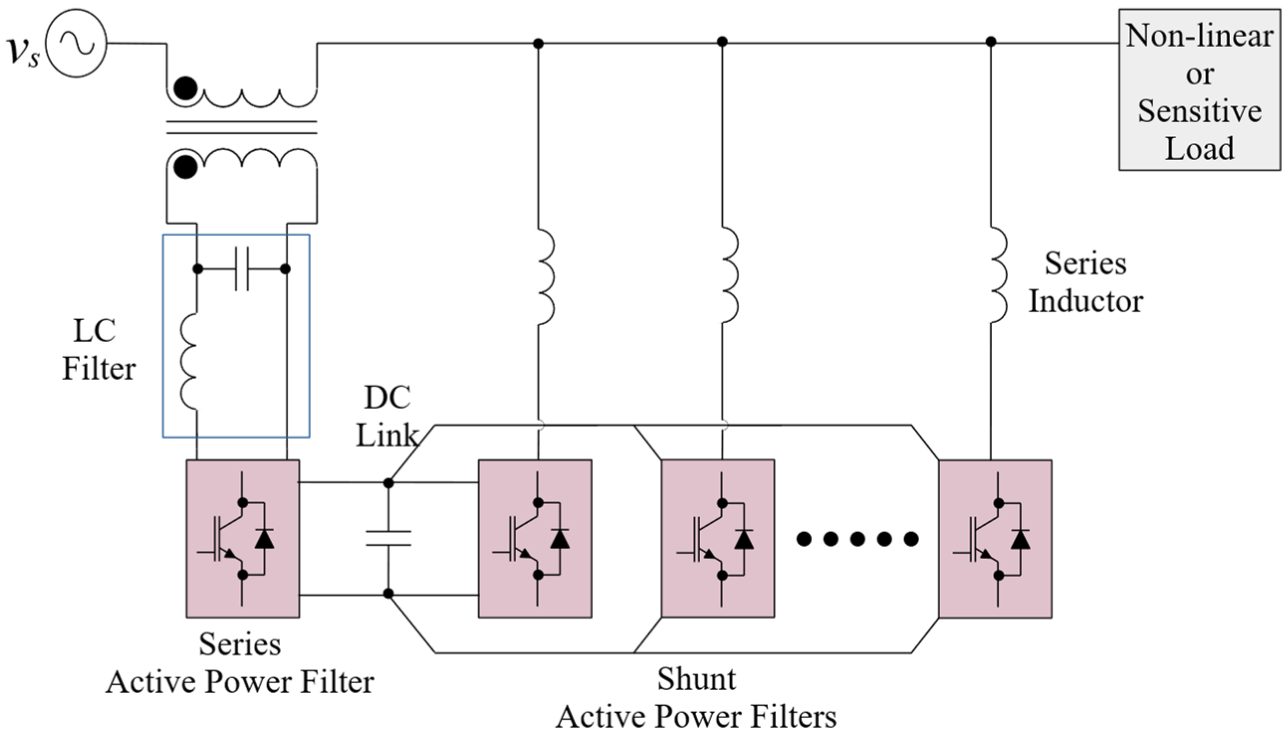
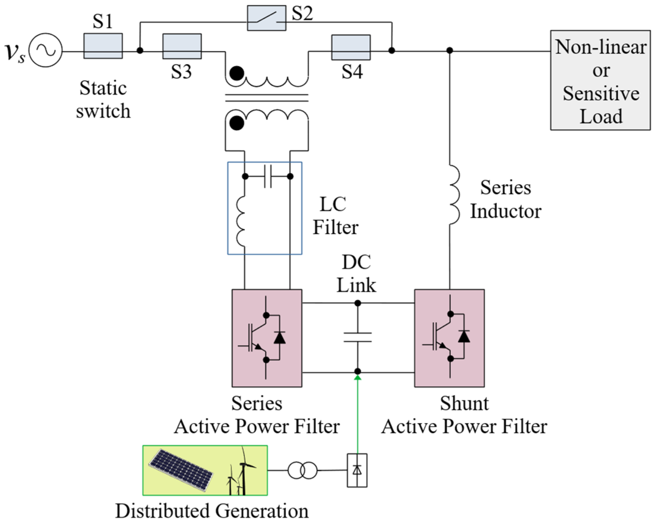
2.1. UPQC
- DC link—a capacitor or an inductor depending on the UPQC converter topology;
- LC filter—a low-pass filter that reduces high system switching ripple caused by the series APF;
- series inductor—it is a high-pass filter that reduces waves during switching modes;
- injection transformer—supplies the series APF.
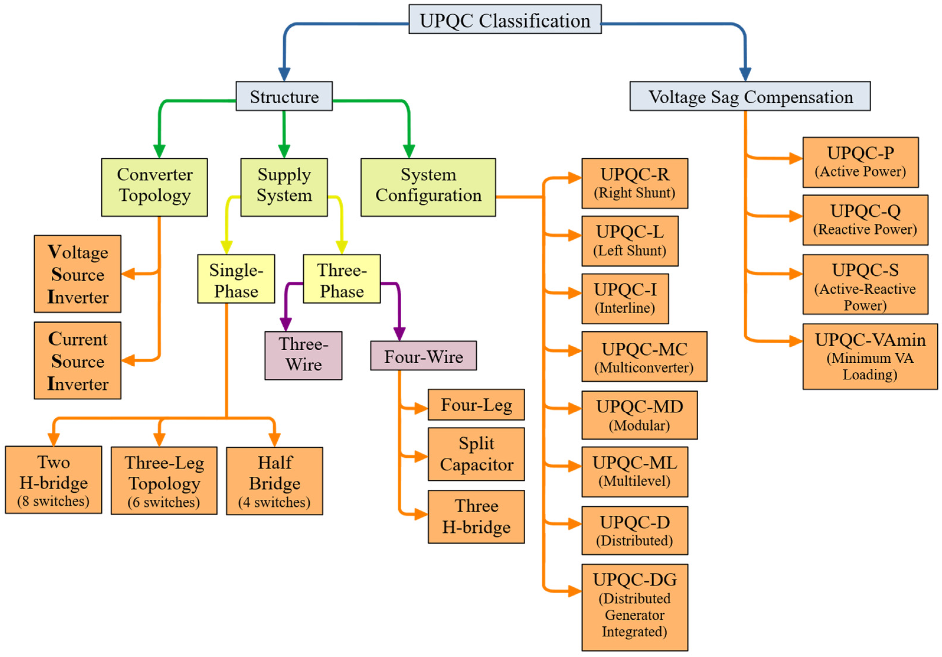
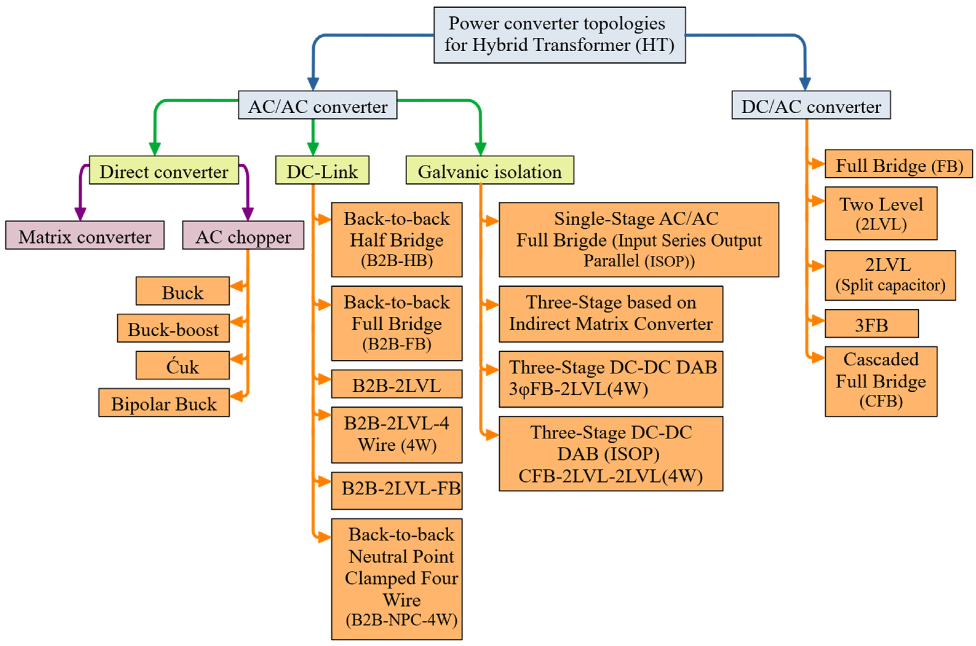
2.1.1. Power Converter Topology
2.1.2. Power Supply System
2.1.3. System Configuration
- UPQC Right Shunt (UPQC-R) and UPQC Left shunt (UPQC-L)
- b.
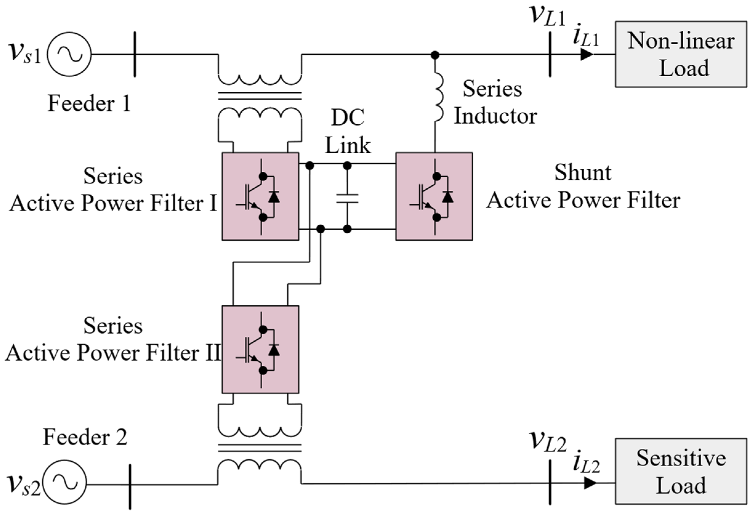
- UPQC Interline (UPQC-I)
- c.
- UPQC Multiconverter (UPQC-MC)
- d.
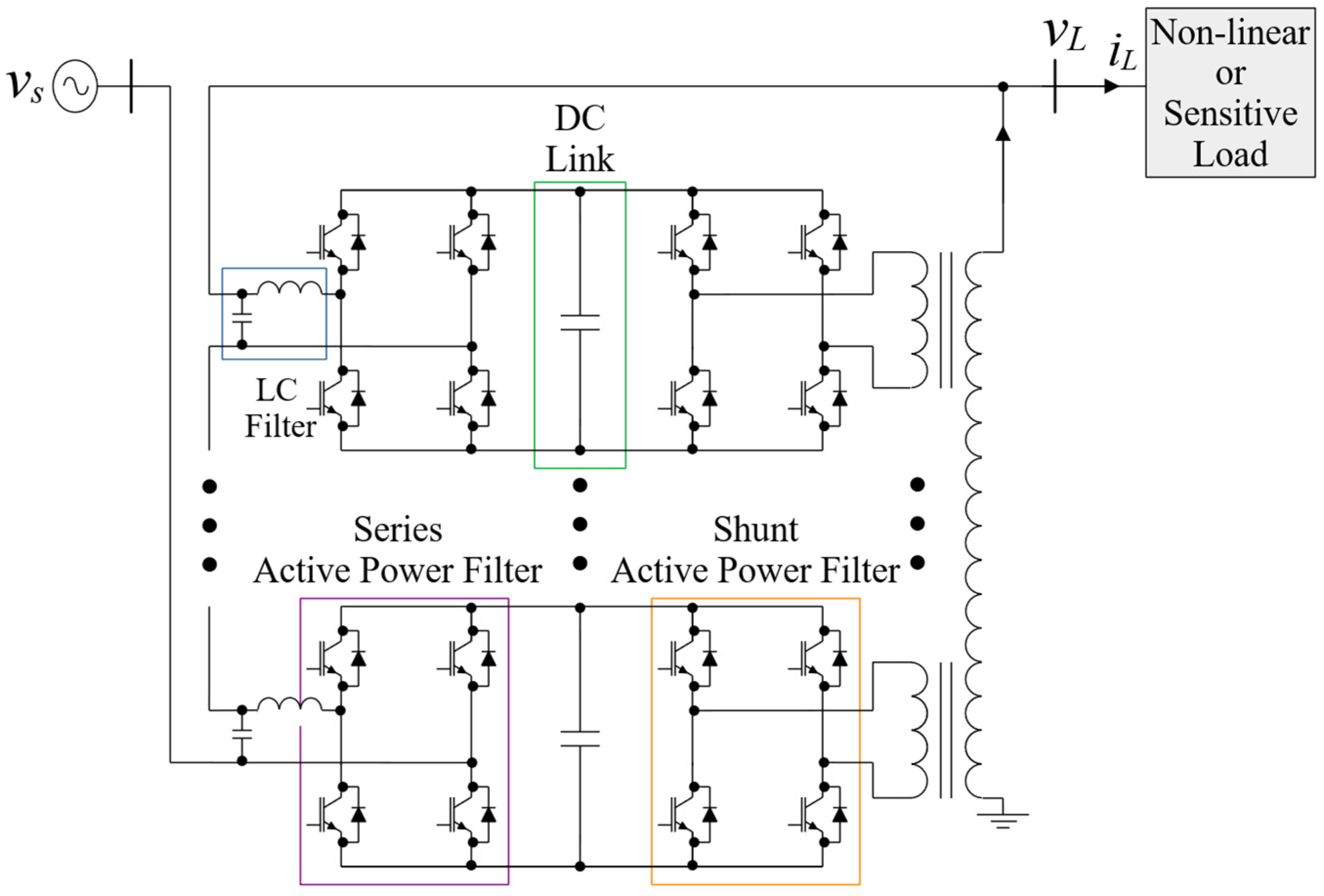
- UPQC Modular (UPQC-MD)
- e.
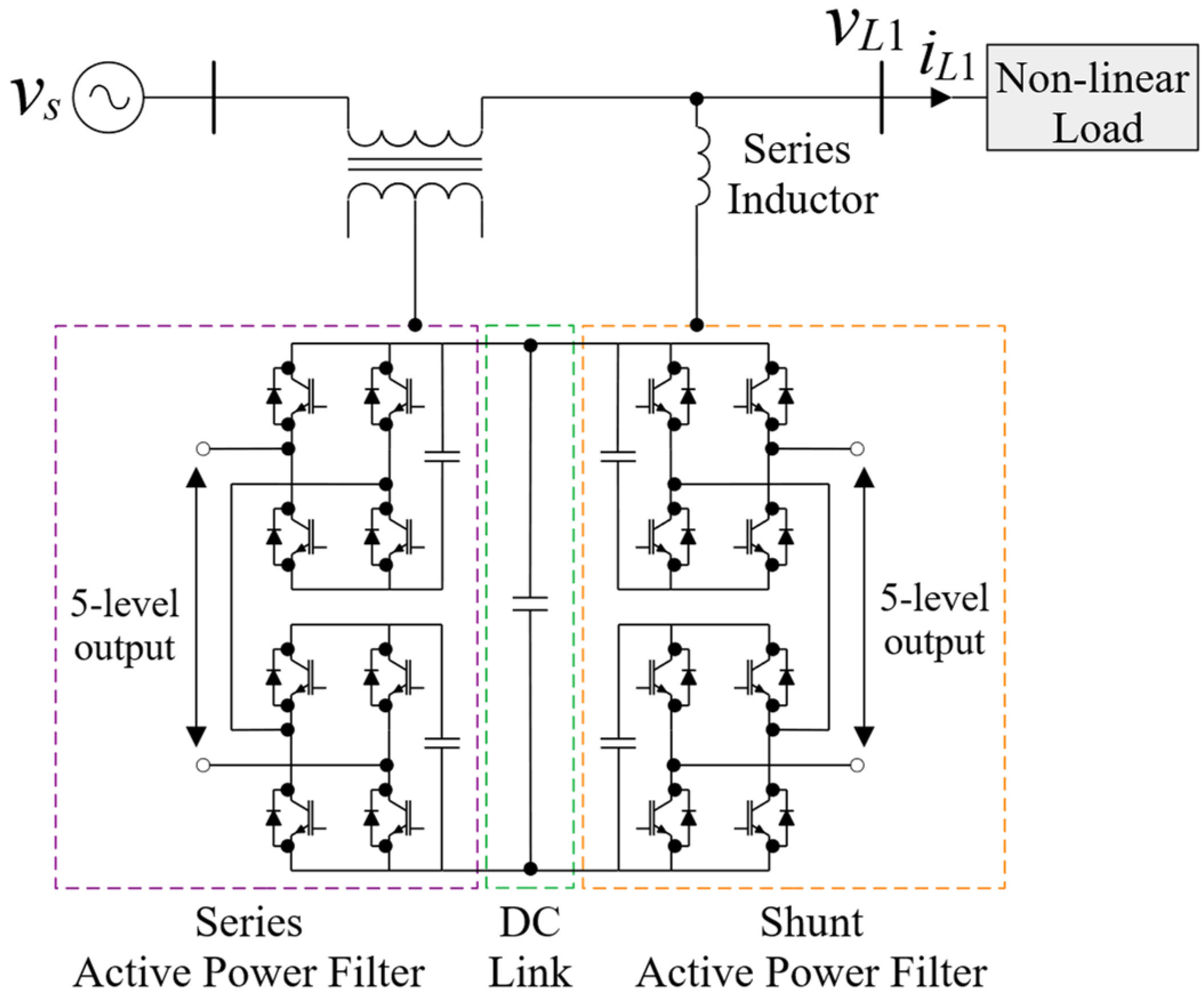
- UPQC Multilevel (UPQC-ML)
- f.
- UPQC Distributed (UPQC-D)
- g.
- UPQC Distributed Generation Integrated (UPQC-DG)
2.1.4. Voltage Sag Compensation
- UPQC-P is a type in which active power is controlled. The series APF introduces active power to mitigate the problem of voltage sags in the power supply;
- UPQC-Q is a type in which reactive power is controlled. The series APF introduces reactive power to mitigate the problem of voltage sags in the power supply;
- UPQC-S is a type in which active and reactive power is controlled. The series APF introduces both active and reactive power to mitigate the problem of voltage sags in the power supply;
- UPQC-VAm is a type that reduces the VA of load to compensate for voltage sags. In addition to the in-phase or quadrature of voltage injection by the series APF at minimum VA, the load voltage is injected with an optimal angle.
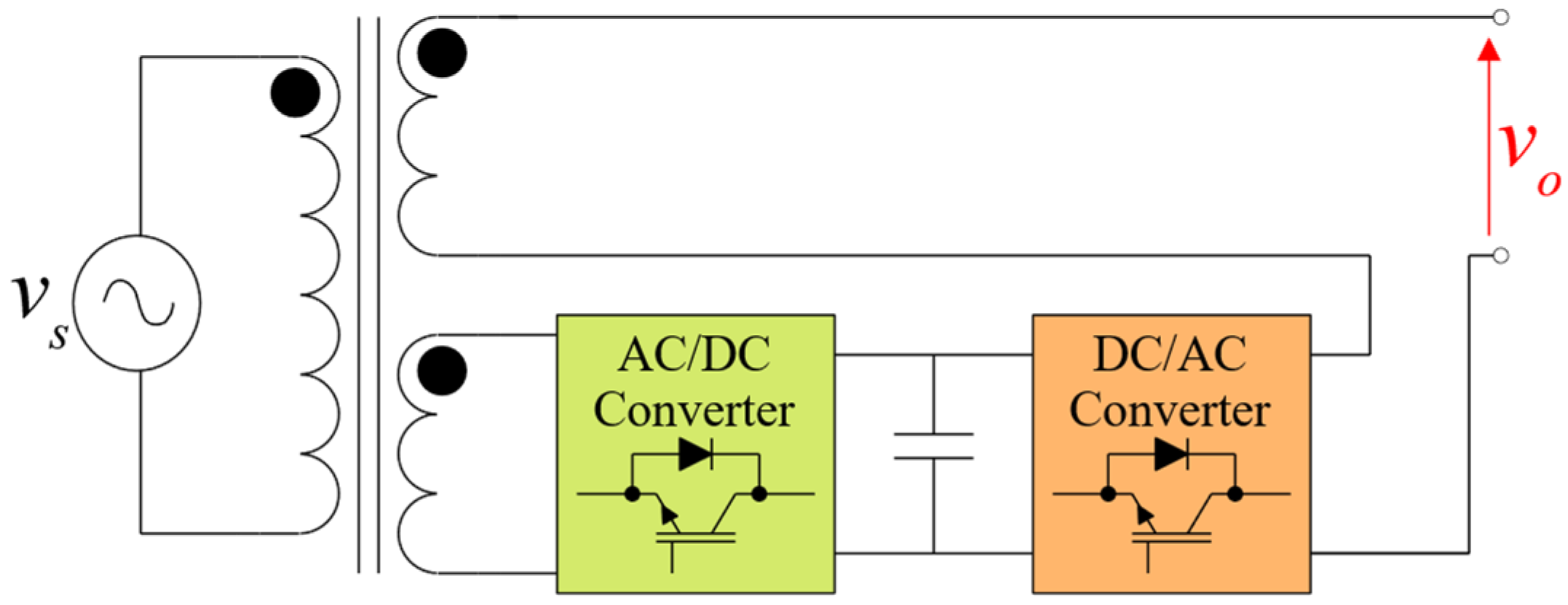
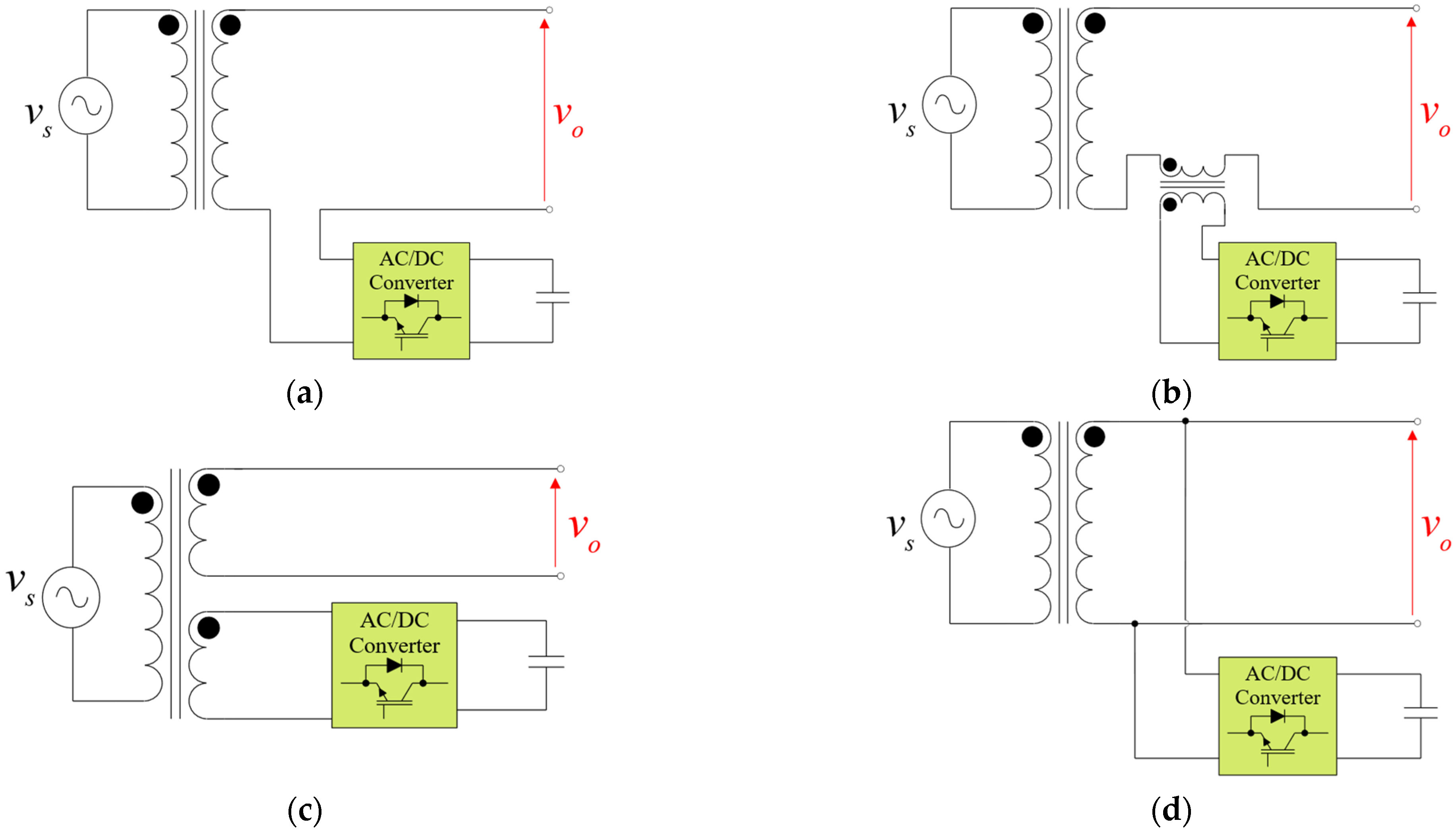
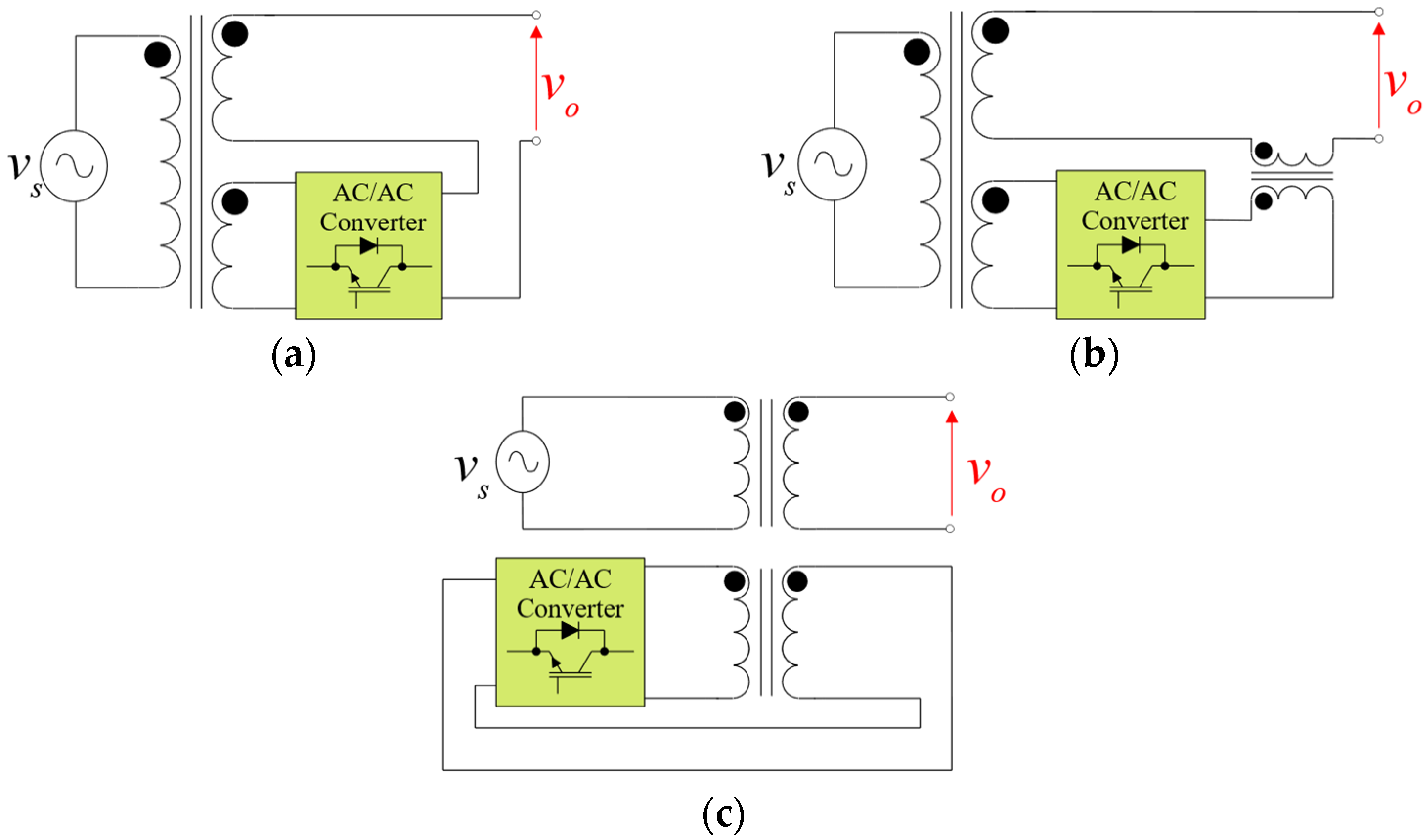
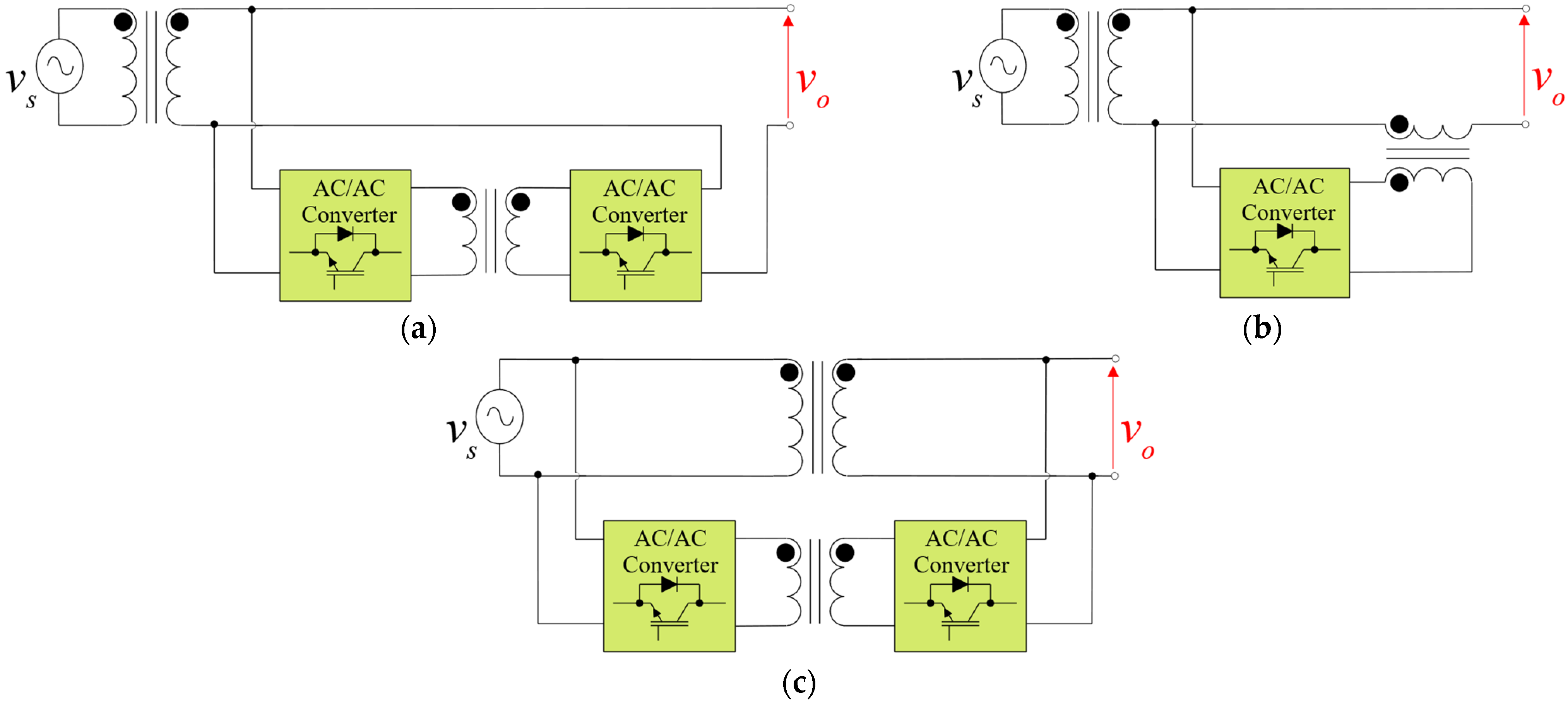
2.2. HT
- reactive power injection;
- restricted active and reactive power injection;
- unrestricted active and reactive power injection.
3. Control Methods of the UPQC and the HT
3.1. UPQC
- voltage stabilization of the DC link [31];
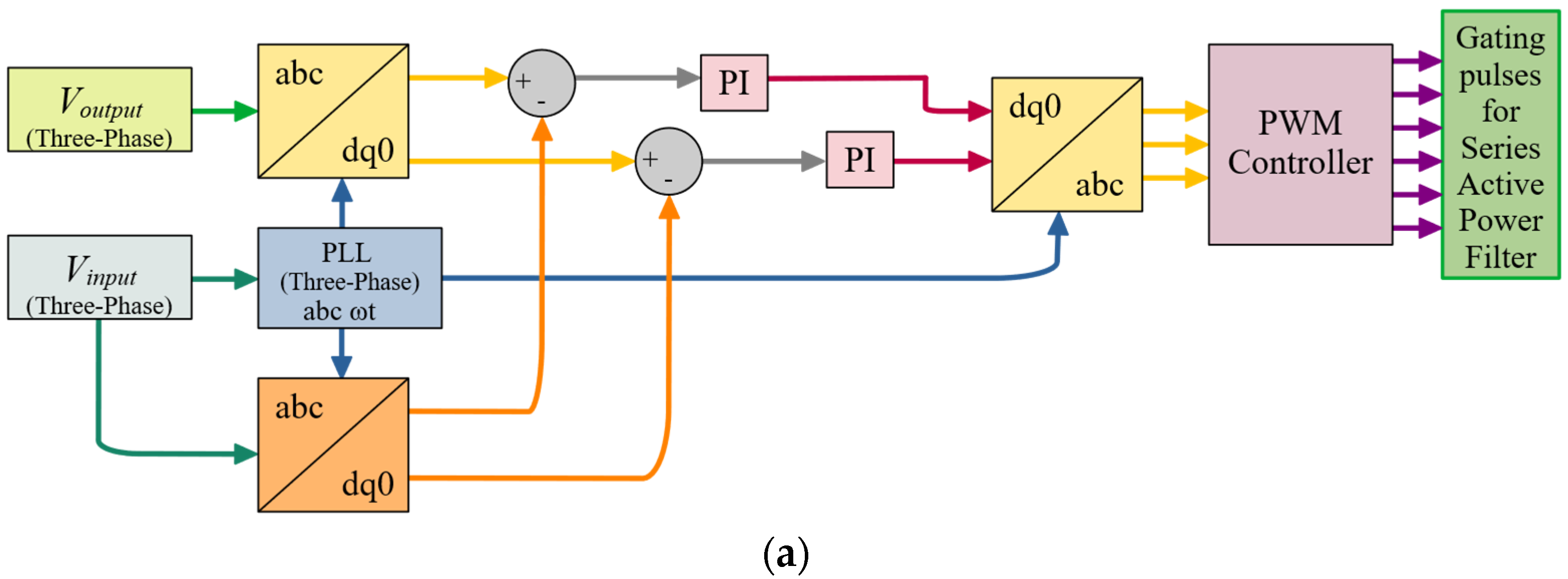
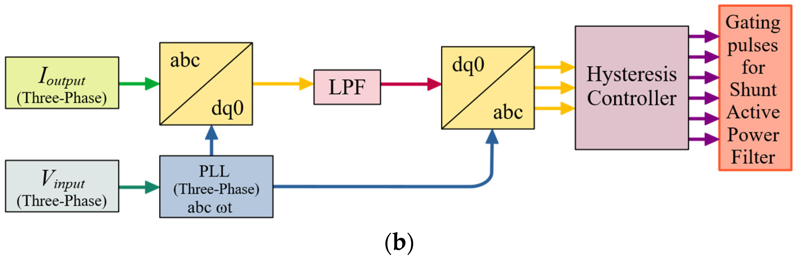
3.1.1. Voltage Sag/Swell and Harmonic Compensation
3.1.2. DC Link Voltage Stabilization/Control
3.1.3. System Response to Non-Linear Load Changes
3.2. HT
- regulation of the reactive power [36]
4. Basic Properties of the UPQC and the HT
4.1. UPQC
4.2. HT
5. Application of the UPQC and the HT
5.1. UPQC
- SVC—Static VAR compensation (reactive power);
- harmonic suppression;
- current balancing;
- active and reactive power regulation;
- voltage balancing;
- voltage compensation.
5.2. HT
- voltage compensation;
- harmonic compensation;
- active and reactive power regulation;
- voltage regulation.
6. Conclusions
Author Contributions
Funding
Data Availability Statement
Conflicts of Interest
Abbreviations
| Acronym | Reference Abbreviation |
| 1P2W | Single-Phase Two-Wire |
| 3P3W | Three-Phase Three-Wire |
| 3P4W | Three-Phase Four-Wire |
| AC | Alternating Current |
| APF | Active Power Filter |
| AVC | Adaptive Power Compensator |
| AW | Auxiliary Winding |
| BESS | Battery Energy Storage Systems |
| CP | Custom Power |
| CSI | Current Source Inverter |
| CT | Coupling Transformer |
| CPD | Custom Power Device |
| DC | Direct Current |
| DG | Distributed Generation |
| DSTATCOM | Distribution Static Compensator |
| DVR | Dynamic Voltage Restorer |
| FOCV | Fractional Open Circuit Voltage |
| HT | Hybrid Transformers |
| IT | Information Technology |
| LC | Inductance—L, capacitance—C |
| LFT | Low Frequency Transformer |
| MPPT | Maximum Power Point Tracking |
| PC | Personal Computer |
| PI | Proportional–Integral |
| PLC | Programmable Logic Controller |
| PLL | Phase-Locked Loop |
| PV | Photovoltaic |
| PWM | Pulse-Width Modulation |
| RMS | Root Mean Square |
| SOGI | Second-Order Generalized Integrators |
| SRF | Synchronous Reference Frame |
| SVC | Static VAR (reactive power) Compensation |
| UPS | Uninterruptible power supply |
| UPQC | Unified Power Quality Controller |
| UPQC-D | UPQC Distributed |
| UPQC-DG | UPQC Distributed Generation Integrated |
| UPQC-MC | UPQC Multiconverter |
| UPQC-MD | UPQC Modular |
| UPQC-ML | UPQC Multilevel |
| VSI | Voltage Source Inverter |
References
- Gosh, A.; Ledwich, G. Power Quality Enhancement Using Custom Power Devices, 1st ed.; Springer: New York, NY, USA, 2002; pp. 1–136, 379–441. [Google Scholar]
- Devaraju, T.; Veera Reddy, V.C.; Vijaya Kuma, M. Role of custom power devices in power quality enhancement: A review. Int. J. Eng. Sci. Technol. 2010, 2, 3628–3634. [Google Scholar]
- Yao, Z.; Chen, W.; Jin, Q.; Liu, X.; Wu, X. Review of the key technology of power quality improvement device for middle-low voltage distribution network. In Proceedings of the 8th ACPEE, Tianjin, China, 14–16 April 2023. [Google Scholar]
- Han, Y.; Xu, L. A survey of the Smart Grid Technologies: Background, motivation and practical applications. Przegląd Elektrotechniczny 2011, 87, 47–57. [Google Scholar]
- Kaniewski, J. Three-Phase Power Flow Controler based on bipolar AC/AC converter with matrix choppers. In Proceedings of the SPEEDAM, Amalfi, Italy, 20–22 June 2018. [Google Scholar]
- Khadkikar, V. Enhancing electric power quality using UPQC: A comprehensive overview. IEEE Trans. Power Electron. 2012, 27, 2284–2297. [Google Scholar]
- Heenkenda, A.; Elsanabary, A.; Seyedmahmoudian, M.; Mekhilef, S.; Stojcevski, A.; Ab Aziz, N.F. Unified power quality conditioners based different structural arrangements: A comprehensive review. IEEE Access 2023, 11, 43435–43457. [Google Scholar] [CrossRef]
- Bhosale, S.S.; Bhosale, U.M.; Chavan, U.M.; Malvekar, S.A. Power quality improvement by using UPQC: A review. In Proceedings of the ICCPCCT, Kannur, India, 23–24 March 2018. [Google Scholar]
- Mahela, O.P.; Shaik, A.G. Topological aspects of power quality improvement techniques: A comprehensive overview. Renew. Sustain. Energy Rev. 2016, 58, 1129–1142. [Google Scholar] [CrossRef]
- Sastry, J.; Bala, S. Considerations for the design of power electronic modules for hybrid distribution transformers. In Proceedings of the IEEE Energy Conversion Congress and Exposition, Denver, CO, USA, 15–19 September 2013. [Google Scholar]
- Burkard, J.; Biela, J. Evaluation of topologies and optimal design of a hybrid distribution transformer. In Proceedings of the EPE ECCE-Europe, Geneva, Switzerland, 8–10 September 2015. [Google Scholar]
- Carreno, A.; Perez, M.; Baier, C.; Huang, A.; Rajendran, S.; Malinowski, M. Configurations, power topologies and applications of hybrid distribution transformers. Energies 2021, 14, 1215. [Google Scholar] [CrossRef]
- Chen, N.; Jonsson, L.E. A new Hybrid power electronics on-load tap changer for power transformer. In Proceedings of the IEEE APEC, Charlotte, NC, USA, 15–19 March 2015. [Google Scholar]
- Hingorani, N.G. Introducing custom power. IEEE Spectr. 1995, 32, 41–48. [Google Scholar] [CrossRef]
- Carreno, A.; Perez, M.; Malinowski, M. State-feedback control of a hybrid distribution transformer for power quality improvement of a distribution grid. IEEE Trans. Ind. Electron. 2023, 71, 1147–1157. [Google Scholar] [CrossRef]
- Pathik, B.B.; Islam, S.; Akram, N.M.; Zaman, M.S.; Al-Nahian, M.A. Total harmonic distortion reduction in a power grid: A UPQC based approach. In Proceedings of the 3rd ICREST, Dhaka, Bangladesh, 7–8 January 2023. [Google Scholar]
- Jindal, A.K.; Gosh, A.; Joshi, A. Interline unified power quality conditioner. IEEE Trans. Power Deliv. 2007, 22, 364–372. [Google Scholar] [CrossRef]
- Mohammadi, H.R.; Varjani, A.Y.; Mokhtari, H. Multiconverter unified power-quality conditioning system: MC-UPQC. IEEE Trans. Power Deliv. 2009, 24, 1679–1686. [Google Scholar] [CrossRef]
- Karelia, N.; Sant, A.V.; Pandya, V. Comparison of UPQC topologies for power quality enhancement in grid integrated renewable energy sources. In Proceedings of the 16th INDICON, Rajkot, India, 13–15 December 2019. [Google Scholar]
- Han, B.; Bae, S.; Baek, S.; Jang, G. New configuration of UPQC for medium-voltage application. IEEE Trans. Power Deliv. 2006, 21, 1438–1444. [Google Scholar] [CrossRef]
- Reddy, V.N.; Kumar, D.V.A.; Reddy Kota, V. A multilevel UPQC for voltage and current quality improvement in distribution system. Int. J. Power Electron. Drive Syst. 2019, 10, 1932–1943. [Google Scholar]
- Khadem, S.K.; Basu, M.; Conlon, M.F. Capacity enhancement and flexible operation of unified power quality conditioner in smart and microgrid network. AIMS Energy 2018, 6, 49–69. [Google Scholar] [CrossRef]
- Yasmeena; Das, G.T.R. A review of UPQC topologies for reduced DC link voltage with MATLAB simulation models. In Proceedings of the ICETETS, Pudukkottai, India, 24–26 February 2016. [Google Scholar]
- Dheeban, S.S.; Muthu Selvan, N.B. PV integrated UPQC for sensitive load. In Proceedings of the IC-ETITE, Vellore, India, 24–25 February 2020. [Google Scholar]
- Yadav, S.K.; Patel, A.; Mathur, H.D. Study on comparison of power losses between UPQC and UPQC-DG. IEEE Trans. Ind. Appl. 2022, 58, 7384–7395. [Google Scholar] [CrossRef]
- Nagaraju, S.; Bethi, C.; Kumar, K.V.; Muni, T.V.; Varma, N.S.V.; Kumar, P.R. Dynamic voltage restorer based solar PV system connected grid utilizing UPQC with fuzzy. In Proceedings of the INCOFT, Belgaum, India, 25–27 November 2022. [Google Scholar]
- Reddy, G.R.; Rayaguru, N.K.; Karthikumar, K.; Chandrasekar, P.; Murthy, P. Enhancement of power quality with fuzzy based UPQC in grid integrated and battery assisted PV system. In Proceedings of the 2nd GCAT, Bangalore, India, 1–3 October 2021. [Google Scholar]
- Silva, S.A.O.D.; Modesto, R.A.; Sampaio, L.P.; Campanhol, B.G. Dynamic improvement of a UPQC system operating under grid voltage sag/swell disturbances. IEEE Trans. Circuits Syst. II Express Briefs 2023. [Google Scholar] [CrossRef]
- Abin, P.; Afsher, P.A.; Manoj, M.V.; Asokan, O.V. Advance PLL based PV-UPQC under adverse grid conditions. In Proceedings of the IEEE IAS GlobConET, London, UK, 19–21 May 2023. [Google Scholar]
- Mohammed, B.S.; Rama Rao, K.S.; Ibrahim, R.; Perumal, N. Performance evaluation of R-UPQC and L-UPQC based on a novel voltage detection algorithm. In Proceedings of the IEEE ISIEA, Bandung, Indonesia, 23–26 September 2012. [Google Scholar]
- Jain, A.; Panda, K.P.; Bhullar, S. Operation of unified power quality conditioner with photovoltaic arrays. In Proceedings of the IEEE IAS GlobConHT, Male, Maldives, 11–12 March 2023. [Google Scholar]
- Jiang, P.; Liu, Y.; Li, Z.; Wang, L.; Gao, Y.; Jing, F. Research on a new unified power quality comprehensive management device for distribution network. In Proceedings of the IEEE 6th ITNEC, Chongqing, China, 24–26 February 2023. [Google Scholar]
- Pateriya, A.; Jain, P. Application of UPQC-PV in medium voltage radial distribution system to mitigate voltage sag-swell. In Proceedings of the International Conference RTEICT, Bangalore, India, 27–28 August 2021. [Google Scholar]
- Andrews, A.; Scaria, R. Three-phase single stage solar PV integrated UPQC. In Proceedings of the 2nd ICICICT, Kannur, India, 5–6 July 2019. [Google Scholar]
- Zhu, M.; Li, H.; Zou, H.; Chen, M. A Novel UPQC architecture based on optical storage cooperation and its DC bus voltage stabilization control strategy. In Proceedings of the IEEE 3rd ICIBA, Chongqing, China, 26–28 May 2023. [Google Scholar]
- Wang, Y.; Zhao, T. Var Control capability analysis for a hybrid voltage regulation transformer. In Proceedings of the IEEE APEC, Houston, TX, USA, 20–24 March 2022. [Google Scholar]
- Prystupczuk, F.; Rigoni, V.; Keane, A.; O’Donnell, T. System-level benefits study of hybrid power electronic transformers in LV distribution grids. In Proceedings of the IEEE PESGM, Denver, CO, USA, 17–21 July 2022. [Google Scholar]
- Zheng, L.; Marellapudi, A.; Chowdhury, V.R.; Bilakanti, N.; Kandula, R.P.; Saeedifard, M.; Grijalva, S.; Divan, D. Solid-state transformerf and hybrid transformer with integrated energy storage in active distribution grids: Technical and economic comparison, dispatch, and control. IEEE J. Emerg. Sel. Top. Power Electron. 2022, 10, 3771–3787. [Google Scholar] [CrossRef]
- Wang, C.; Huang, Y.; Hou, F.; Li, K. Modeling and simulation of a new hybrid transformer for metro traction power supply system. In Proceedings of the IEEE 5th CIEEC, Nangjing, China, 27–29 May 2022. [Google Scholar]
- Lee, H.J.; Yoon, S.W.; Yoon, Y.D. Hybrid distribution transformer based on an existing distribution transformer and a series-connected power converter. IEEE Trans. Power Deliv. 2022, 37, 4202–4211. [Google Scholar] [CrossRef]
- Wang, R.; Huisman, H.; Wijnands, K. Distribution transformer voltage control using a single-phase matrix converter. In Proceedings of the 24th EPE’22 ECCE Europe, Hanover, Germany, 5–9 September 2022. [Google Scholar]
- Wang, Y.; Zhao, T. A hybrid voltage regulation transformer based on interline power converters. In Proceedings of the IEEE APEC, Houston, TX, USA, 20–24 March 2022. [Google Scholar]
- Aeloiza, E.C.; Enjeti, P.N.; Moran, L.A.; Pitel, I. Next generation distribution transformer: To address power quality for critical loads. In Proceedings of the IEEE 34th PESC, Acapulco, Mexico, 15–19 June 2003. [Google Scholar]
- Kaniewski, J.; Fedyczak, Z.; Benysek, G. AC voltage sag/swell compensator based on three-phase hybrid transformer with buck-boost matrix-reactance chopper. IEEE Trans. Ind. Electron. 2014, 61, 3835–3846. [Google Scholar] [CrossRef]
- Yadav, S.K.; Patel, A.; Mathur, H.D. Comparison of power losses for different control strategies of UPQC. In Proceedings of the IEEE 9th PIICON, Sonepat, India, 28 February–1 March 2020. [Google Scholar]
- Amirullah; Adiananda; Penangsang, O.; Soeprijanto, A. A Dual UPQC to mitigate sag/swell, interruption, and harmonics on three phase low voltage distribution system. In Proceedings of the 3rd ICVEE, Surabaya, Indonesia, 3–4 October 2020. [Google Scholar]
- Vinnakoti, S.; Kota, V.R. SRF and real power theory based control of a nine switch converter based UPQC. In Proceedings of the IEECON, Pattaya, Thailand, 8–10 March 2017. [Google Scholar]
- LahuNikam, S.; Sandeep, K.K. Analysis of modified three-phase four-wire UPQC design. In Proceedings of the 3rd ICONSTEM, Chennai, India, 23–24 March 2017. [Google Scholar]
- Mukassir, S.M.; Mudassir, S.M.M.; Sultana, S.; Giribabu, D. The new trend in power conditioning using multi-converter unified power-quality conditioning (MC-UPQC) for multi feeder system. In Proceedings of the ICECDS, Chennai, India, 1–2 August 2017. [Google Scholar]
- Han, B.; Bae, B.; Kim, H.; Baek, S. Combined operation of unified power-quality conditioner with distributed generation. IEEE Trans. Power Deliv. 2006, 21, 330–338. [Google Scholar] [CrossRef]
- Szcześniak, P.; Powroźnik, P.; Sztajmec, E. Selected voltage control methods in LV local distribution grids with high penetration of PV. Prz. Elektrotechniczny 2023, 99, 62–65. [Google Scholar]


| References | Description | Differences from This Article |
|---|---|---|
| [4] | Key technological issues for the construction of smart grids were presented with a special discussion of the most important elements of a smart grid, such as uninterruptible power supply (UPS), adaptive power compensator (AVC), static synchronous compensator (STATCOM), active power filter (APF), unified power quality conditioner (UPQC). | Other compensator topologies are discussed. Discussion of the topology as an element of the smart-grid system. There is no description of the control method in the context of compensation of distribution network voltage changes. |
| [6] | The topology and properties of the UPQC were reviewed in the context of improving the quality of electricity in the distribution network. Different configurations of the UPQC system for single-phase (two-wire) and three-phase (three-wire and four-wire) networks are shown. | This article mainly focuses on presenting various UPQC topologies, without detailing the control strategy. Only a description of the various system studies is presented. |
| [7] | This article mainly focuses on the presentation of various UPQC topologies and the details of the control strategy. In addition, it briefly summarizes the description of other works on UPQC systems. | Similar topics without taking into account the HT configuration. |
| [9] | A very short and general overview of energy quality improvement devices. Topology nomenclature and basic properties are defined. | Much shorter descriptions and also description of other topologies without showing the HT topology. |
| [10,11] | The TH concept and various possible configurations of the electromagnetic transformer are described. In addition, selected topologies of power electronic converters used in HT are listed. | Common part of this article describes the TH concept and various possible configurations of the electromagnetic transformer. This article does not discuss the converter topology in detail. The focus was only on the use of HT to compensate for voltage changes. |
| [12] | A very wide review of power electronic converters used in HT and their properties. Description of voltage distortion compensation methods and description of possible application places in the power system. | A more detailed description of the converter topology used in HT. AC/AC topology without DC energy storage is not included. |
| Type of | Description | Causes | Consequences |
|---|---|---|---|
| Voltage sag/dip | Root Mean Square (RMS) voltage drop from 10–90% of nominal RMS voltage value lasting from a half cycle of a power frequency to one minute | Large loads (e.g., large motors), improper installation of equipment by the customer, short circuits in the installation | Failure of IT equipment and electromechanical relays, equipment malfunction, or damage |
| Voltage swell | RMS voltage escalation from 110–180% of nominal RMS voltage value, lasting from half cycle to one minute | Capacitor switching, start/stop heavy loads, source voltage variation, badly adjusted distribution transformers | Loss of data, increase in flickering of lights and TV screens, equipment damage |
| Very short interruptions | Total disturbance or power interruption lasting from a few milliseconds to one or two seconds | Insulation failure, lightning strike, opening and re-closing of power protection devices | Triggering of protection devices in the power system, stopping the operation of sensitive loads such as data processing instruments, PCs, PLCs, etc. |
| Long interruptions | Total power outage lasting more than 2 s | Thunderstorms or trees, that hit a transmission or distribution line or electric poles; fire in the distribution network or substations, failure of the protection devices | Suspension of operation of all devices connected to the distribution network |
| Voltage spike | Voltage value changes lasting from a few microseconds to a few milliseconds. The voltage value can jump up to thousands of volts | Lightning strike, disconnection of heavy loads, switching of power factor correction capacitors | Destruction of electrical equipment and insulation, loss of data, electromagnetic interference |
| Harmonic distortion | Non-sinusoidal voltage or current waveforms | Non-linear receivers, power electronic converters, arc furnaces, welding machines | Probability of resonance, overheating of lines and devices, interference in adjacent communication systems, errors in the signal measurements |
| Voltage fluctuations and flicker | Cyclical or random change or oscillation of the voltage waveform near its nominal value | Arc furnaces, repeated starts and stops of electric motors, oscillating electric loads | Flickering lights and TV screens |
| Overvoltage | Rise of 10–20% in the nominal RMS voltage value for more than one minute | Switching off heavy loads, energized capacitor bank | Damage household appliances |
| Undervoltage | Dip of 10–20% in the nominal RMS voltage value for more than one minute | De-energized capacitor bank, switching on loads | Increased loss and heating |
| Noise | High frequency signals on the frequency signal of the power system | Electromagnetic interference, improper grounding | Interference with sensitive electronic equipment |
| Voltage imbalance | In the three-phase system, the voltage values or phase angles between the three phases are not equal | Large single-phase loads, uneven distribution of loads over the three phases | Negative sequence voltage and current appears, which is detrimental to all three-phase loads |
| Type of Compensation | Energy Source | |||||||||
|---|---|---|---|---|---|---|---|---|---|---|
| Capacitor | AW | LFT | ||||||||
| (a) | (b) | (c) | (d) | (a) | (b) | (c) | (a) | (b) | (c) | |
| from Figure 17 | from Figure 18 | from Figure 19 | ||||||||
| Series without the CT | √ | √ | √ | |||||||
| Series with the CT | √ | √ | √ | |||||||
| Shunt | √ | √ | √ | √ | ||||||
| Magnetic | √ | √ | √ | √ | ||||||
| The Series APF | The Shunt APF |
|---|---|
| (1) The supply voltages balance by inserting equal and negative components to remove those present in the system; | (1) The source currents balance according to the load requirements by inserting equal and negative components; |
| (2) The load protection from harmonics by introducing voltage harmonics into the supply; | (2) The required harmonic current injection to compensate those present in the system; |
| (3) The required active and passive elements introduction to regulate the magnitude of the load voltage; | (3) The reactive current injection for power factor control; |
| (4) Adjustment of the input power factor. | (4) The DC link voltage management and synchronization. |
Disclaimer/Publisher’s Note: The statements, opinions and data contained in all publications are solely those of the individual author(s) and contributor(s) and not of MDPI and/or the editor(s). MDPI and/or the editor(s) disclaim responsibility for any injury to people or property resulting from any ideas, methods, instructions or products referred to in the content. |
© 2023 by the authors. Licensee MDPI, Basel, Switzerland. This article is an open access article distributed under the terms and conditions of the Creative Commons Attribution (CC BY) license (https://creativecommons.org/licenses/by/4.0/).
Share and Cite
Sztajmec, E.; Szcześniak, P. A Review on AC Voltage Variation Compensators in Low Voltage Distribution Network. Energies 2023, 16, 6293. https://doi.org/10.3390/en16176293
Sztajmec E, Szcześniak P. A Review on AC Voltage Variation Compensators in Low Voltage Distribution Network. Energies. 2023; 16(17):6293. https://doi.org/10.3390/en16176293
Chicago/Turabian StyleSztajmec, Elżbieta, and Paweł Szcześniak. 2023. "A Review on AC Voltage Variation Compensators in Low Voltage Distribution Network" Energies 16, no. 17: 6293. https://doi.org/10.3390/en16176293
APA StyleSztajmec, E., & Szcześniak, P. (2023). A Review on AC Voltage Variation Compensators in Low Voltage Distribution Network. Energies, 16(17), 6293. https://doi.org/10.3390/en16176293