Abstract
In Poland, hydrogen production should be carried out using renewable energy sources, particularly wind energy (as this is the most efficient zero-emission technology available). According to hydrogen demand in Poland and to ensure stability as well as security of energy supply and also the realization of energy policy for the EU, it is necessary to use offshore wind energy for direct hydrogen production. In this study, a centralized offshore hydrogen production system in the Baltic Sea area was presented. The goal of our research was to explore the possibility of producing hydrogen using offshore wind energy. After analyzing wind conditions and calculating the capacity of the proposed wind farm, a 600 MW offshore hydrogen platform was designed along with a pipeline to transport hydrogen to onshore storage facilities. Taking into account Poland’s Baltic Sea area wind conditions with capacity factor between 45 and 50% and having obtained results with highest monthly average output of 3508.85 t of hydrogen, it should be assumed that green hydrogen production will reach profitability most quickly with electricity from offshore wind farms.
1. Introduction
Decarbonization of the energy sector is a strategic priority required to fulfill the climate goals of the Paris Agreement in 2015 [1]. The International Energy Agency (IEA) estimates that in 2019, almost 84% of the world’s primary energy originated from non-renewable sources. Oil accounted for 36% of this supply, followed by coal and natural gas at about 27% and 17%, respectively. The primary causes of climate change are fossil fuels, which when burned emit a tremendous amount of greenhouse gases. [2]. The European Union (EU) has established a long-term policy of comprehensive decarbonization by 2050 to meet these long-term climate goals by transitioning its economy from utilizing fossil-based energies to alternative energy sources and technology [3,4]. Individual objectives have been set by European Union nations, including Poland, to increase the percentage of energy derived from renewable sources [5]. Many European countries have opted to radically rearrange their power production mix with offshore wind being one of its important aspects. It is generally necessary to reduce global greenhouse gas emissions and, especially due to the changing geopolitical circumstances linked with the crisis in Ukraine, ensure energy security in Europe [6,7]. One of the most widely used renewable energy sources is wind, as seen by the swift increase in installed wind turbine capacity in numerous nations [5]. Wind energy generation has increased rapidly during the last few decades. Its utilization climbed from 0.2% to 4.8% of total power output between 2000 and 2018, and is anticipated to reach more than 12% by 2040 [8]. Many European countries have turned their focus to the study and development of offshore renewable energy, citing various benefits over onshore energy resources. The availability of greater and continuous wind speeds, as well as unrestricted area for building renewable energy systems, are the primary benefits of offshore location. However, the installation and operational costs, as well as the advanced technology needs for power transmission and integration into the onshore electric grid, may pose some challenges for offshore renewable energy development [2]. Offshore wind installed capacity is predicted to double globally during the next decade, rising from around 50 GW in 2021 to 225 GW in 2030. In 2030, Europe will account for nearly half of worldwide offshore wind capacity; Asia will account for around 40% of global installed capacity, and the United States will account for the remaining 10%. Offshore wind is considered as a logical transition for many oil and gas corporations, who have decades of offshore technical knowledge and are increasingly focused on shifting their operations away from fossil fuels and toward renewable energy. Offshore wind may be utilized to power offshore platforms, reduce carbon emissions from oil and gas production, and generate hydrogen [9]. For some years, in Europe and also in Poland, there has been a tremendous interest in offshore wind energy. It is supported by significantly superior wind conditions at sea than on land, as well as steadily lowering off-shore farm investment costs.
The Baltic Sea region, including Poland’s exclusive economic zone, has been identified as having particularly ideal circumstances for offshore wind production. The entire installed offshore wind capacity in the Baltic Sea is just 2.8 GW, accounting for around 10% of European and 5% of global installed capacity. However, the Baltic Sea, along with the North Sea, is expected to become a significant offshore wind European hub in the near future. The Baltic Sea has a total size of 397,978 km2 and is surrounded by nine nations [6]. The Baltic Sea provides highly favorable circumstances, such as shallow seas (average depth of around 54 m), high average wind speeds (approximately 9 m/s at 100 m amsl), low wave heights, and weak tides, resulting in relatively low costs for offshore wind energy generation. By 2030, the offshore wind capacity installed in the Baltic Sea will account for about 22% of the volume commissioned in Europe. Poland has tremendous potential for offshore wind development [6]. The estimates range from 28 GW to 45 GW for offshore wind turbines in the Polish section of the Baltic Sea in 2050 [10]. Offshore wind energy (OWE) technology has the potential to become the leading source of renewable energy in Poland’s energy mix by 2040. Poland’s current Energy Policy till 2040 states a target of at least 23% RES in gross final energy consumption by 2030 [10]. In the event that its total estimated potential is used, by 2040 OWE could meet as much as 57% of Poland’s total electricity demand. Offshore wind energy is a technology that can provide a significant volume of generation capacity with good parameters related to the stability of energy production. The offshore wind projects with a total capacity of about 8.4 GW are being developed in Polish marine areas, including [7]:
- −
- Phase I development projects with a total capacity of 5.9 GW (for which start-up dates are indicated by investors for 2025–2027),
- −
- Phase II development projects with a total capacity of 2.5 GW (which, according to the law, will be entitled to apply for the right to offset the negative balance in auctions scheduled for 2025 and 2027).
The area of Poland, in terms of weather conditions conducive to the use of wind en-ergy, is divided into zones, where the criterion for division is wind speed. The best wind conditions are found in the Baltic Sea, the coastal part of which has a high energy potential, and in the northwestern area of Poland covering the entire coastal belt, as well as in the northeastern areas around the Suwalskie Lake District. In Poland, the best wind conditions prevail in the autumn and winter months and during the day, with slightly worse conditions prevail at night [11,12,13]. A crucial technology for the growth of renewable energy in Poland is offshore wind energy, as it is the most predictable source of electricity among renewable energy technologies, with higher capacity utilization rates than on-shore farms and photovoltaic farms. Offshore wind farms are characterized by a relatively high annual efficiency factor (Capacity Factor), which in the Polish Baltic Sea zone oscillates between 45–50% [14]. In addition, the electricity generated by offshore wind farms can be partially used to power power-to-X processes that convert electricity into liquid synthetic fuels, hydrogen, synthetic natural gas (SNG) or ammonia [15]. Offshore wind energy, which has the greatest capacity utilization rate of all RES, must be set aside for direct hydrogen synthesis, without taking the demands of the power system’s balance into account or requiring the connection of generating sources and electrolysers to the grid (off-grid operation). There are a number of technological ways to link offshore wind turbines, electrolysers, transport pipes, storage facilities, and other installation structural elements [10]. There are basically two different system configurations: the centralized system, which consists of an offshore wind farm, an offshore electrolyser, as well as onshore hydrogen storage facility, and the decentralized system, which has both the electrolyser and the hydrogen storage facility on land. In comparison to long-distance power transmission through HVDC or HVAC lines, the transfer of energy from offshore windmills converted to hydrogen is more affordable [10]. When combined with renewable energy sources, hydrogen becomes even more appealing. In this situation, it may also be employed as an electrical energy storage device, which may be critical in minimizing the gap between renewable energy production and consumer demand [16]. The ability to store the energy surpluses in hydrogen greatly improves the performance of wind power systems [17]. During times of excess supply, power may be transformed into green hydrogen and stored for later use. In times of supply constraint, the hydrogen stored can be turned back into electricity [8]. Hydrogen, as a recognized clean energy, will play an increasingly essential part in the future energy system due to its benefits of being pollution free, enabling diversified application, inducing minimal losses, high utilization rates, and allowing convenient transportation [18]. Hydrogen may be used as an energy storage option, with dispatchable fuel cells powered by green hydrogen producing electricity when needed while emitting no carbon dioxide [19]. Poland ranked third in Europe in terms of hydrogen production in 2019, with producing around one million tonnes per year (34 TWh). This output was fully devoted to meeting home demands, the majority of which were industrial in nature. This is a volume that renewable hydrogen may be able to replace. In Poland, annual demand for hydrogen is expected to surpass 100 TWh [10]. Offshore wind farm hybrid production will boost system flexibility, but depending on business goals and system designs, it may necessitate extra capital expenditures in technology and infrastructure as desalination, electrolysis, compression, transmission, liquefaction, and storage [20].
The interest in the offshore production of green hydrogen is constantly growing, as confirmed by a number of initiatives led by some of the most important energy companies. However, these initiatives still stand at a pioneering stage and the MW scale is the target [21]. Offshore hydrogen production is currently being developed in various concepts to bring far-offshore or floating wind to shore [22]. The computation of the cost of hydrogen generation utilizing an offshore wind power facility was published in article [23]. To examine the economic aspects of hydrogen generation linked to a wind power plant, three design variants are considered [23]:
- Case 1: Distributed hydrogen production. Each wind turbine is outfitted with an electrolysis equipment, and hydrogen is created utilizing power generated directly on floating structures. Each turbine produces hydrogen, which is collected on the seafloor through risers and manifolds and sent onshore via a gas pipeline.
- Case 2: Centralized hydrogen production. A large-scale electrolysis system is constructed on an offshore platform next to a wind farm, receiving produced power to manufacture hydrogen and later delivering it to land through a gas pipeline.
- Case 3: Onshore hydrogen production: an offshore substation is built near the wind power plant, and the voltage is raised enough to supply currents onshore and transport them through high-voltage cables. This is a typical system of transmission for offshore wind farms.
The electrolysis system configuration and technique of transmitting produced energy to land based on the identical wind power plant circumstances distinguished the presented three examples. Similarly, in [24] Singlitico et al. presented of an offshore Hub, where AC-electricity from surrounding offshore wind power parks is converted to DC, and then transported onshore via HVDC. For far wind power parks, this concept has been found more cost-effective than the radial HVDC connections for far wind farms, benefiting from the economies of scale of collecting a large amount of power. In study proposed a reference case of a 12 GW Hub, located 380 km from Esbjerg (Denmark) is presented. Three distinct electrolyser sites, as well as their associated infrastructures, have been studied [24]:
- Onshore.
- Offshore: All offshore wind farms’ power is routed to the Hub, where hydrogen is created by a single electrolyser using desalinated seawater, compressed, and supplied to shore by pipeline.
- In-turbine: Electrolysers and desalination units are installed within or near to each wind turbine’s tower. The hydrogen generated is sent to the Hub via pipes that connect groupings of wind turbines. Then the hydrogen is collected, compressed, and piped to shore from the Hub.
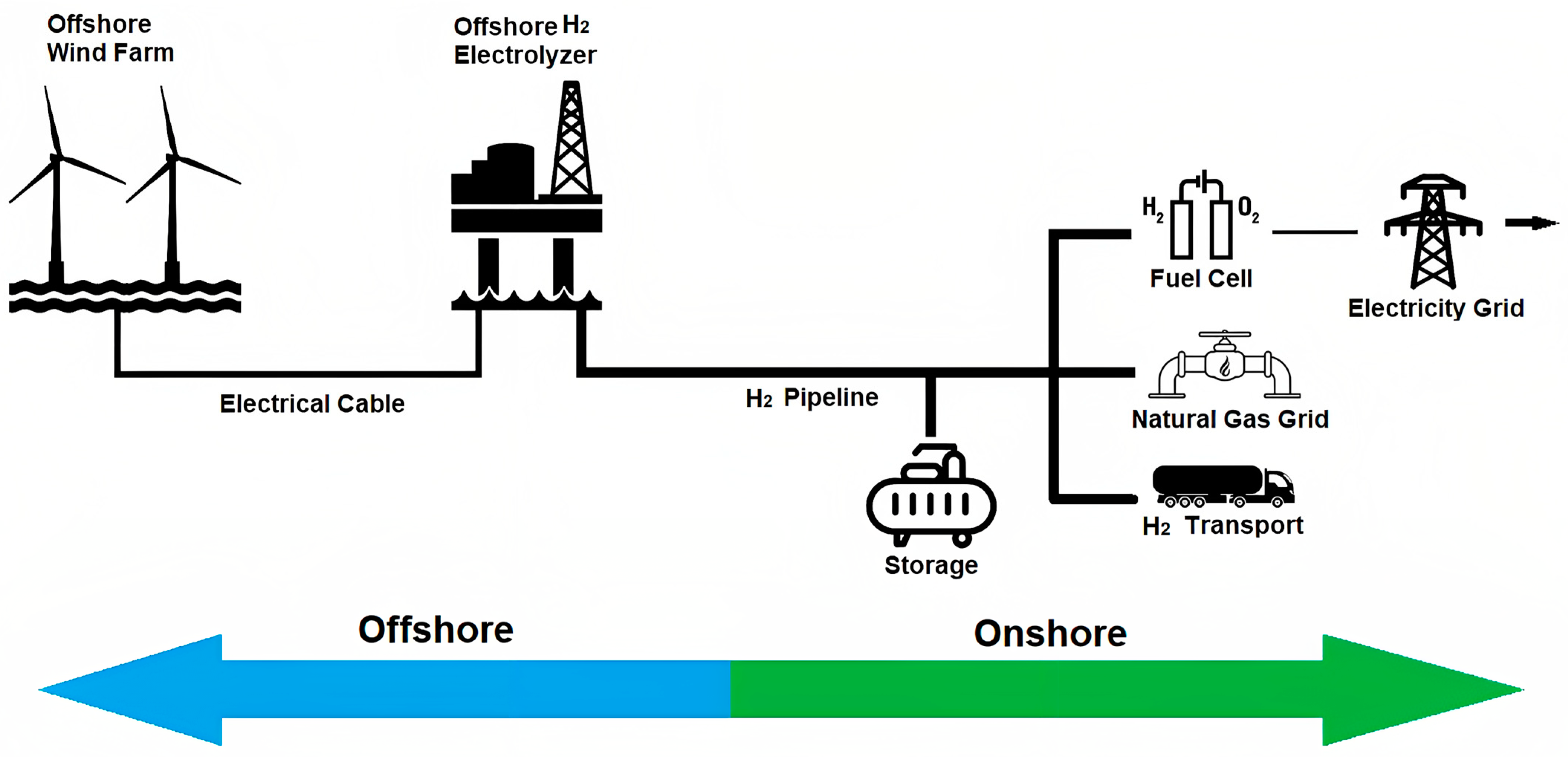
One of the concepts is the centralized conversion of offshore wind on an offshore platform for hydrogen production. This concept is presented in [1,22]. The seawater is desalinated and used to feed the electrolyser that converts offshore wind power into hydro-gen, oxygen, and heat. As up to 80% of the power needed for this process is captured in hydrogen, hydrogen is used as a carrier to transport energy via a pipeline to shore. The oxygen and heat are released into the air. This concept is studied in two options: full conversion of offshore wind into hydrogen, or partial conversion of the energy into hydrogen and partially electric power conversion to HVDC for transport. In the second option, an HVDC power cable is still required, but the energy transport can be optimised between electrons and molecules, delivering to different energy markets onshore, which offers an opportunity to maximise the value of the wind power and optimise the load factor of the power cable [22]. The PosHYdon is a pilot project for the demonstration of hydrogen production from renewable power in an offshore environment. The objective is to install an electrolysis-based hydrogen production system on an existing offshore platform (Q13a, managed by Neptune Energy). The platform is connected to shore via a 25 kV cable that provides connection to both the electrical grid as well as the internet (through fiber optics included in the power cable) [1]. Henry et al. [25] have also emphasized the use of platforms for green hydrogen production, as well as the possibility for the oil and gas sector to create H2 during the energy transition. This is related to the requirement to decommission around 600 installations that could be utilized. In [9], the central hydrogen production platform collects power from wind turbines and transfers it to a central platform through array cables. Electrolysers on the center platform generate hydrogen, which is subsequently piped back to shore. This idea saves money by eliminating the need for export cables and land-based substations. The paper by G. Calado and R. Castro [19] claimed that two offshore wind-powered hydrogen generation systems are now being suggested. This is accomplished by either offshore or onshore electrolysis. The advantages of offshore electrolysis include lower energy transport costs and fewer transmission losses. Losses in a High Voltage Alternating Current (HVAC) transmission line are roughly 1% to 5% for wind farms with nominal output ranging from 500 to 1000 MW and located 50–100 km from coast. The losses in an HVDC system are 2% to 4%, depending on the nominal power and distance. However, hydrogen traveling through a pipeline has far smaller losses, less than 0.1% [19]. The scheme of offshore hydrogen production system present Figure 1:

Figure 1.
Schemes of offshore hydrogen production system. Source: [19].
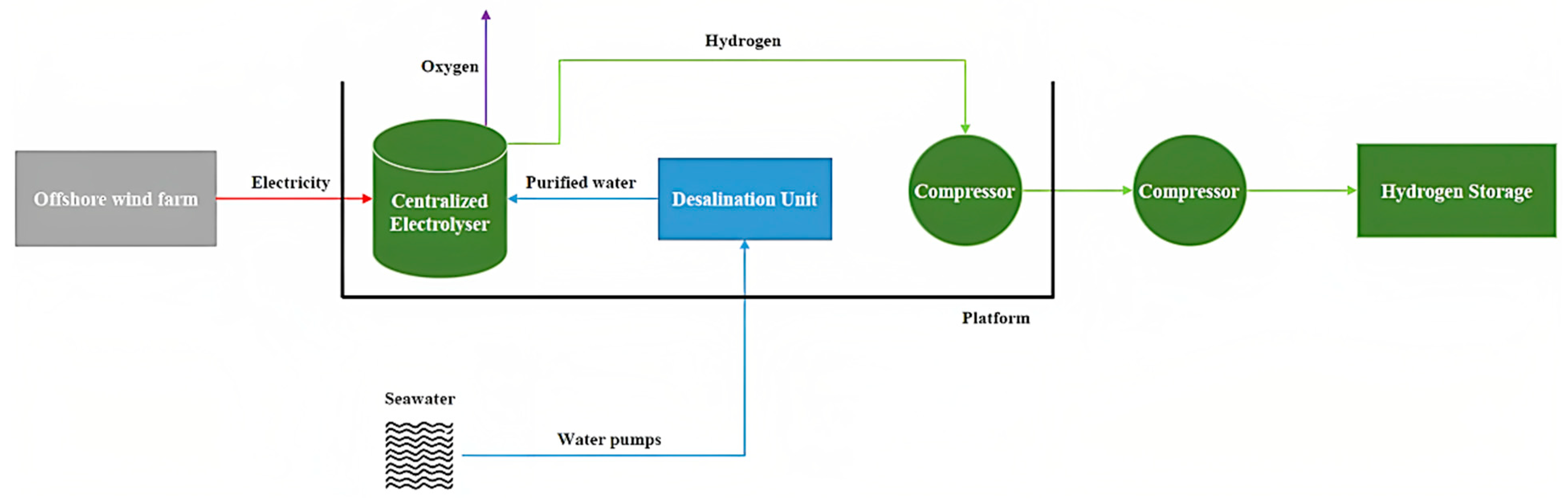
The electricity generated by each individual turbine is delivered to a central platform through ordinary undersea cable in a centralized electrolyser system. The majority of the electrical power may be corrected to DC once it reaches the central platform. The second component is utilized to provide AC power to the hydrogen compressors and seawater pumps [19]. A desalination system is used to purify sea water. After being desalinated in the desalination unit, the water is demineralized and injected into the electrolyser. The electrolyser then splits water into hydrogen and oxygen using electricity [26]. The hydrogen generated by the electrolyser departs with a pressure of 30 bar and high purity, therefore the next step is to compress it to the necessary pipeline input pressure. After compression, the hydrogen is put into the export pipeline and transported to the beach, while the oxygen is either released into the atmosphere at the same time or collected [19,26]. This concept is shown in Figure 2:

Figure 2.
The centralized offshore hydrogen production. Source: own materials based on [26].
There are numerous electrolysis methods for generating hydrogen. The oldest and most frequent of these is alkaline electrolysis (AEC), which uses potassium or sodium hydroxide as the electrolyte. The plants utilized for this purpose have component life of 50–90,000 h, an efficiency of 65–82%, and the ability to scale up output in around 60 s [9]. Proton exchange membrane (PEM) electrolysers use a polymeric membrane as an electrolyte. The benefits of PEM technology include higher efficiency (65–78%), but also a shorter lifetime (30–90 thousand hours). Solid Oxide Electrolysis Cell (SOEC) is the least mature technology and is not yet commercially deployed. Such installations need a temperature of 800–1000 °C (and thus a continual source of significant amounts of heat) and are characterized by low efficiency and component life (around 10–30 thousand hours), yet their efficiency can reach 85% [9]. One important disadvantage of AEC and PEM electrolysers is the requirement to utilize valuable and semi-precious metals as catalysts (e.g., platinum, cobalt, or nickel), which greatly raises electrolysis prices. Anion Exchange Membrane (AEM) electrolysers, which are currently under research but have not yet been commercialized, may provide a solution by producing hydrogen under alkaline electrolysis conditions without the usage of precious metals [9].
Proton exchange membrane (PEM) electrolysers are the optimum choice for centralized offshore system due to their reduced footprint and ease of maintenance, which implies that in an offshore environment, the platform may be smaller and maintenance visits can be further apart. Since a PEM’s output pressure is roughly 30 bar, further compression is necessary to export the hydrogen to land. The size of the hydrogen compression system and pipeline to land must be determined by the distance to shore, the working pressure of the electrolyser, the hydrogen flow, and the pressure drop along the pipeline [19]. Lucas et al. [4] claim that the PEM electrolysis technology is best suited for hydrogen production from wind energy due to its quicker reactions and higher performance at partial load, and hydrogen production from an offshore wind farm seems promising despite its reliance on several factors, with the electrolyser’s capacity factor being highlighted. In [27] different water electrolysis technologies are considered: AEC, PEM, and SOEC. The power generated by offshore wind turbines is supposed to be delivered by cable to the coast, where centralized electrolysers create hydrogen. For gaseous hydrogen storage, pressurized tanks are the default option. The PEM electrolysers were the most convenient for offshore technology. The paper deals with the coupled operation of electrolyser and wind turbine were presented by Sarrias-Mena et al. [17]. Four different electrolyser models are presented and evaluated in this work. Also, in [28,29] we can see the concept of centralized offshore hydrogen generation. Many scientific studies are now being conducted on dedicated offshore wind farms for hydrogen generation. The centralized strategy with offshore hydrogen generation from a specialized wind farm produced the lowest LCOE in [29]. In this situation, hydrogen is produced offshore. The offshore wind farms provide direct electricity to the electrolysers. Dinh et al. [30] established a novel integrated and analytical model for estimating the profitability of hydrogen generation from dedicated offshore wind farms. The case study involved a hypothetical 101.3 MW wind farm placed in an offshore wind development pipeline off Ireland’s east coast. Electrolysers with proton exchange membranes and subsurface hydrogen storage were utilised. The offshore wind farm-hydrogen production system was shown to be feasible in 2030, with a hydrogen price of €5/kg and subterranean storage capacity ranging from 2 to 45 days [30]. Bonacina et al. [31] also evaluate a specialized wind farm, a hydrogen production facility with electrolysis, liquefaction, and storage facilities. The wind power plant generates renewable energy, the electrolyser stack produces hydrogen, the water treatment unit produces demineralized water, and the facility for hydrogen liquefaction stores and distributes hydrogen to ships. For each unit, the technology that best matches the offshore hydrogen production application is selected from the state-of-the-art technologies. Offshore plants have higher wind power density and stability, as well as more available space than onshore ones [31]. In terms of operational benefits, rather of docking in a port, an offshore installation speeds up and simplifies ship refueling. In the article of Ibrahim et al. [32] the offshore electrolysis plant is housed on a floating vessel in a centralized arrangement. It includes electrolysers, cooling units, seawater desalination units, a hydrogen buffer, and a battery system providing backup power to the facility, similar to the decentralized type. It might possibly have compressors. The performance of a wind—PEM electrolyser system was assessed for hydrogen generation in the study by Akyuz et al. [33]. The output of the wind turbine’s electric energy was also calculated using the hourly average wind speed. It was presented in [34] to simulate and evaluate the functioning of a wind-hydrogen system based on a floating offshore wind turbine and hydrogen generation via water electrolysis. The technical modeling was carried out using a MATLAB Simulink model of a semi-empirical proton exchange membrane (PEM) water electrolyser system. The major input for the simulations was data from a 2.3 MW floating offshore wind turbine that has been operating off the West coast of Norway since 2009. The Simulink model was created to mimic an energy system in which water electrolysis is utilized to manufacture hydrogen using power from an offshore wind turbine [34]. Cho et al. [35] suggested a P2G system that will be set up by a water-electrolysis facility near an existing wind farm on Jeju Island with a maximum generation capacity of 9.38 MW. The P2G system is normally intended to produce 200 kg of hydrogen per day (with a maximum capacity of 600 kg per day). In order to attain productivity, 3.3 MW of electrolysis facilities and auxiliaries were configured. Cheng et al. [36] described an offshore wind and onshore solar PV-powered system that generates renewable electricity, which is fed into an electrolyser for water electrolysis and hydrogen generation. When the electrolyser has spare capacity, the stored power is recovered. A techno-economic study of three offshore wind power plant configurations, including dispersed hydrogen production, centralized hydrogen production, and onshore hydrogen production, was provided in a paper by Jang et al. [37] to find the most economical technique of linking offshore wind power plants with hydrogen production facilities.
Recognizing the safety issues of hydrogen is critical for achieving dependable, secure, and efficient use of hydrogen as an alternative to fossil fuels. Hydrogen is no more or less risky than other combustible fuels. Indeed, the hydrogen’s lightness, and hence its ability to disperse quickly in the case of a leak, reduces the potential of aggregation and ignite. Since hydrogen does not contain carbon, its flames produce little radiant heat. However, due to the wide flammability range, colorless, odorless, tasteless, and essentially undetectable flame properties, hydrogen leaking is very hard to detect without adequate instruments [21]. International standards such as NFPA 2, NFPA 55, or ISO standards give major indicators for particular safety criteria for various hydrogen applications (for example, gaseous hydrogen, liquid hydrogen, vehicle fueling facilities and stations, and hydrogen fuel cell power systems). The European Union member countries addressed the definition of the main requirements to hydrogen production operators in terms of Risk Assessments under the Seveso Directive, Health and Safety requirements and conformity assessment procedures under the ATEX Directive, Integrated Environmental Obligations under the IED, and Environmental Impact Assessment procedures under the SEA and EIA Directives, as well as important amendments [21].
As can be seen from the work presented earlier, with the rise of offshore wind generation, hydrogen is emerging as a possible solution for the intermittent nature of renewable energy sources and long-distance transmission. This study discusses the possibility for producing hydrogen utilizing offshore wind energy from the Baltic Sea on a dedicated offshore platform. The first chapter presents basic information on offshore wind hydrogen production and a literature review. The second chapter contains the main submissions of the ongoing research. Chapters three and four contain the results and their discussion, while chapter five summarizes the entire article. The article will help fill the research gap regarding the possibility of using hydrogen produced on an offshore platform in Poland’s energy system.
2. Materials and Methods
2.1. Introduction
In this article a conception of centralized offshore hydrogen production system in the Baltic Sea area was presented. According to [19,38], the individual wind turbine installation in a centralized electrolyser system is the same as that of a normal offshore wind farm, with turbines in strategic positions to reduce losses due to wave impacts. Each turbine’s power is delivered to a central platform through undersea cables; while voltages vary, newer, higher-powered turbines run at 66 kV. The majority of the power may be rectified into direct current once it reaches the central platform The remaining is utilized to power seawater pumps and an alternating current hydrogen compressor. The direct current is primarily utilized for hydrogen generation, but it is also used to power the auxiliary systems. During shutdown periods, when the electrolyser must consume a tiny amount of energy to remain in standby mode, the electrolyser must have a power supply. Due to the PEM’s capacity to start running at 1% of nominal power, although at poor efficiency, shutdown times are uncommon and brief. Fresh water is split into hydrogen and oxygen during the electrolysis, and hence a fresh water source is necessary. Since the hydrogen produced by the electrolyser has a high purity and a pressure of 30 bar, the next step is to compress it to the necessary pipeline input pressure. Following compression, the hydrogen is pumped into the export pipeline and sent to the land. This case considers a wind farm connected to the mainland grid with an HVAC connection in combination with a connection to a platform for hydrogen production. In such a solution, hydrogen platform will receive power from the offshore wind farm when there is sufficient wind, but will also be able to import power from shore as a backup power during periods when there is little wind. In periods of little wind the hydrogen production will be shut. The installed capacity of the wind farm is assumed constant, while the transmission capacity to shore is varied depending on the optimal utilization of electrolyser system capacity. The main components of a centralized electrolyser system on an offshore platform include:
- AC/DC rectifiers
- Cable connection to shore as a backup power source
- PEM electrolyser and auxiliary electronics
- Desalination unit and desalinated water tanks
- Seawater pumping system
- Hydrogen pipeline to shore
- Control and measurement equipment.
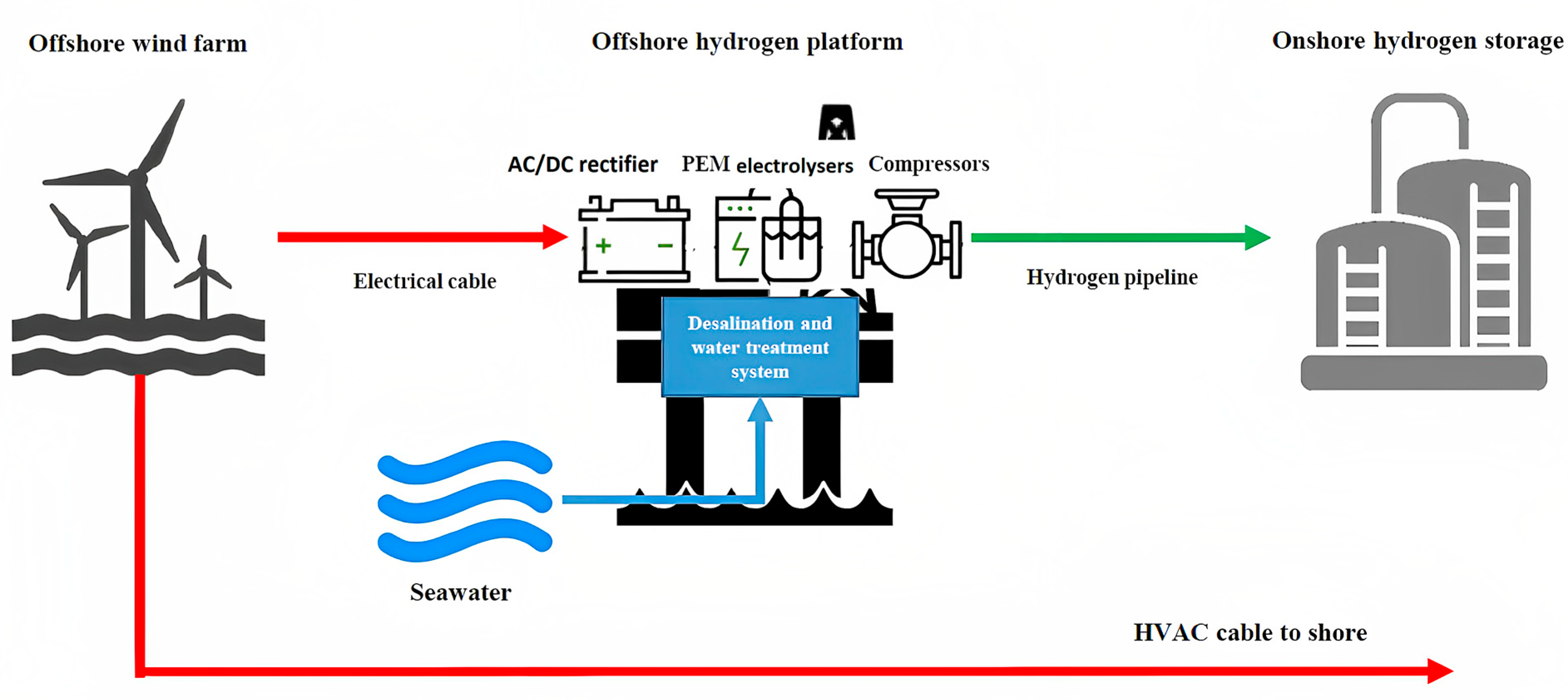
The model of centralized offshore hydrogen production system considered in the article is presented in Figure 3:

Figure 3.
The model of centralized offshore hydrogen production in Baltic Sea. Source: own materials based on [39].
2.2. Wind Farm
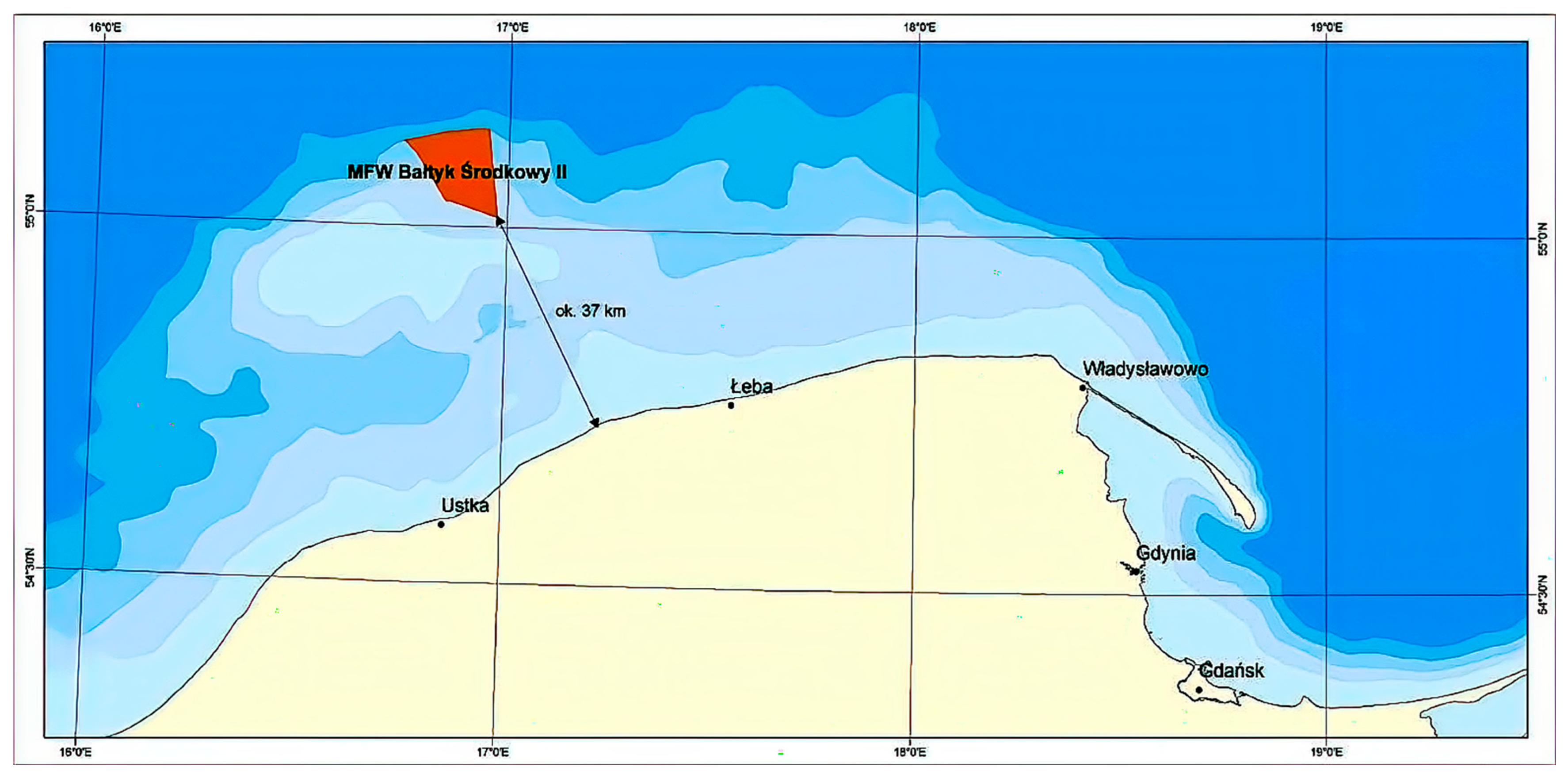
The computations used data from the articles [40,41,42] the projected offshore wind farm Baltic II. The planned location of the wind farm is in the Polish Exclusive Economic Zone, in the southern part of the Baltic Sea, about 37 km in a straight line from the shore, at the level of Smołdzino municipality and Łeba municipality (Pomeranian voivodeship). The total area of the project area is about 122 km2, of which the area on which the power plant can be sited, after taking into account the required buffer areas, it is about 77–78 km2. The geographic coordinates of the points delimiting the Baltic II area has been presented in Table 1. The offshore wind farm’s maximum installed electricity capacity will be 720 MW.

Table 1.
The geographic coordinates of the points delimiting the Baltic II area [40].
Figure 4 depicts the position of the wind farm in the Baltic Sea (marked in orange):

Figure 4.
The site of the Baltic II wind farm on the Baltic Sea (marked in orange). Source: [41].
The Baltic II wind farm area is characterized by good location parameters, i.e., location in relatively shallow waters, in close proximity to the shore, with good wind conditions. As a result, it is possible to apply the most proven and available technologies, i.e., use of the most efficient wind turbines, HVAC (alternating current) connection technology and foundation of the turbines on monopile foundations, which are currently optimal from the cost side. The currently expected lifetime of a wind farm is 25–30 years [7,41].
The following table (Table 2) summarizes the important technological parameters of the Baltic II farm:
Table 2.
Technical parameters of Baltic II [40].
The Baltic II wind farm will be controlled by a Supervisory Control and Data Acquisition (SCADA) information system. The capacity factor for the current areas of the Baltic Sea earmarked for offshore wind farm development varies between 42.7% and 47.4%, depending on the shape and environment of the area, windiness, etc. [7]. A capacity factor of 45% was assumed for the Baltic II farm considered in the article.
Since there was a shortage of measurement data from the intended wind farm location, the onshore station nearest to the area under consideration was chosen. Hourly wind speed data were available for the onshore station Łeba with the identifier 12,120 at a height of 10 m above ground level. Data for the year 2021 were obtained from ogimet.com [43]. Since the proposed wind turbine would be 110 m tall, the wind speed at this height must be calculated. The wind speed was estimated using the following equation [44] at a height of 110 m above sea level:
In this formula, v110 is the wind speed at 110 m, v10 is the wind speed at 10 m, H110 is the turbine height (110 m), H10 is the height the data was taken from (10 m) and α is Hellman’s exponent, for this case 0.2 is chosen [39]. Based on the adjusted wind speeds at an altitude of 110 m, the power output of a single wind turbine was computed.
The following wind turbine characteristics are necessary to model energy production: inlet wind speed, vci (m/s), rated wind speed, vr (m/s), inlet wind speed, vci (m/s), outlet wind speed, vco (m/s), rated power, Pr (MW), and diameter, Dr (m) or rotor area, Ar (m2). Once these parameters are obtained from the turbine, which corresponds to the average wind speed at a given location, the turbine power can be calculated using the following formula [44]:
The ρ (kg/m3) in this equation represents the air density at the hub height, and Ctot is the overall efficiency coefficient (power coefficient) that changes with both wind speed and turbine rotational speed [39]. The following assumptions are taken into account in the calculations:
- It is assumed that each turbine uses the same wind power curve.
- Other turbines’ impacts on wind shear, air density changes, wake effects, and turbulence are ignored.
- The wind farm is 95% operational.
2.3. Wind Turbine Characteristics
The V236-15.0 MW type of Vestas turbine was used to estimate the wind farm’s real output. Table 3 provides a summary of the turbine’s key technical specifications. There will be a total of 48 turbines installed.
Table 3.
Technical parameters of Vestas V236-15.0 MW turbine [45].
The wind profile of the area and the turbine power profile are used to determine the availability of renewable energy at a specific place. Different efficiencies are estimated based on wind speed to generate a turbine power profile for a 15 MW turbine, as illustrated in Table 4. The turbine power at the given wind speeds is then calculated.
Table 4.
Turbine efficiency depending on wind speed at 110 m [26].
2.4. Electrical Conversion and Losses
The losses studied are those caused by power conversion and transmission. The following conversion processes must be undertaken in order to transmit power from the wind farm to the platform and also to the coast through the transmission cables [26,28,38,46]:
- The wind turbine generates DC power, which is subsequently converted to AC to power the array cables (66 kV AC inter-array cables are studied in this study).
- The electricity is then sent through cables through a grid to a converter located on an offshore platform. The AC electricity is then converted to DC and delivered into an electrolyser. The transmission loss is 3%, while the AC-DC loss is 4%.
The portion of the electric energy produced by the offshore wind farm that is not used for hydrogen production is delivered to the shore via HVAC interconnectors in the centralized hydrogen production system. HVAC systems are favored for short-distance power transfer [20].
2.5. Hydrogen Offshore Platform
It is envisaged that the centralized hydrogen production system will be housed on an offshore platform linked to the wind farm grid. An HVAC unit should be installed on this platform to give processed air to the electrical and living areas. HVAC will also provide air to the electrolyser system [26]. The hydrogen generated on the platforms is sent to shore through a subsea hydrogen pipeline for additional gas processing [47]. Based on current available technology the platform will contain the following systems [38]:
- − Desalination and water treatment plant
- − Feed water storage
- − Electrolysers
- − Drying and separator system
- − Cooling system
- − Compensators
- − General area for the safety system
- − Living quarters for maintenance work
The area/weight required for storage, compression or other treatment of the hydrogen is not included in this work. The PEM system offers approximately 50% lower space requirements and weight compared to an alkaline system [38]. Based on the data in [38] and [47], the basic design and dimensions of the offshore platform holding the electrolysis facility and related components are established in this article. Offshore hydrogen platforms face greater footprint and weight limits. The 500 MW hydrogen platform idea was described in [47]. The platform presented in the article is divided into three levels, with water and gas processing on the bottom two levels and electrolysis on the top two levels. To maintain ideal operating temperatures at the electrolysers, a large cooling load is necessary. Heat exchangers installed subsea have been selected for cooling process. Subsea cooling system utilizes the convective cooling produced by the surrounding current, using less water [47]. The platform power capacity will be adjusted to the power obtained from a wind farm.
2.5.1. Electrolyser System
The chosen electrolyser is a MC500 Proton Exchange Membrane (PEM) electrolyser produced by NEL Hydrogen. The PEM electrolyser can immediately adapt to variations in power input when the power source is variable wind energy with fluctuating power generation due to its working range of 10–100% and short reaction time. The PEM electrolyser’s operating pressure of 30 bar is particularly advantageous since it reduces energy usage while compressing the gas. The electrolysers are module-based, the creation of a large scale PEM electrolyser based on wind farm input power [46]. Table 5 summarizes the most important technical parameters of the electrolyser:
Table 5.
NEL MC500 Electrolyser technical specification [48,49].
The ideal size ratio for an electrolysis plant to a wind farm is between 80% and 90% [44]. In this study, the size ratio of the electrolyser to the wind farm is assumed constant at 90%. The PEM system provides about 50% lower space requirements and even lower weight compared to an alkaline system [38]. According to IEAs, the plant footprint of electrolyser technology is 48 m2/MW for PEM [50]. The containerized solution was put forward so as to protect the under-lying and expensive from the atmospheric elements which usually occurs in the offshore environment [38]. The number of individual modules will be selected after taking into account the maximum power dedicated to the electrolysis process.
2.5.2. Hydrogen Production
Depending on the power supplied to the electrolyser system, a corresponding number of electrolyser modules will be activated to produce hydrogen. During short periods when energy from the wind farm will not be produced, the electrolyzers will go into standby mode. For longer power outages, the electrolysers will be turned off. The amount of produced hydrogen is given by the following formula [26,46,51]:
2.5.3. Desalination and Water Tank System
The sea is the source of the feed water for the offshore hydrogen production system, an offshore sized desalination system is necessary owing to the freshwater demand for the electrolyser. A considerable amount of the feed water is returned to the sea as brine, with a projected recovery rate of 40% [46,47]. In this study, the reverse osmosis (RO) desalination system was investigated. To improve water quality, the desalination process can be carried out in stages. A 1-step reverse osmosis desalination produces water with a purity of 200–500 ppm, whereas a 2-step RO desalination produces water with a purity of 10 ppm [52]. The MC500 series Nel Hydrogen electrolyser includes a desalination machine. The amount of water required per hour for an electrolyser is provided by formula [53]:
where wdes is the amount of water used per kilogram of hydrogen, which is assumed to be 15 L of feed water per kilogram of hydrogen [53].
The desalination system’s power consumption (MWh) is determined using the following formula [20,53]:
where edes—energy consumption/1 m3 of water is considered to be 3.5 kWh/m3 [53].
The water tank system will be selected according to the calculated maximum hourly water consumption of the electrolyser unit.
2.5.4. Compressors
PEM electrolysers generate high quality hydrogen at pressures ranging from 2 to 6 MPa, necessitating compression of the generated hydrogen to 10–20 MPa at the pipeline entrance for offshore application. Centrifugal compressors were assumed in this work [20]. When hydrogen is created by the electrolyser, the input energy required to operate the compressor is delivered, and energy is similarly provided to all other equipment on the platform. Since the energy required to operate the compressor is substantially lower than the total energy generated, the loss of hydrogen generation is insignificant. The compressor should be able to handle the highest possible hydrogen flow rate [26].
Equation (6) calculates the compression power needs (P (kW)), and Equation (7) calculates the compressor’s system energy consumption (MWh) [26,53]:
where:
- Q—hydrogen flow rate (kg H2/h),
- Z—hydrogen compressibility factor: 1.03198
- T—temperature at the compressor’s intake: 310.95 K
- R—ideal gas constant: 8.314 J/K·mol
- —hydrogen molecular mass: 2.15 g/mol
- η—compressor system efficiency: 75%
- κ—diatomic constant factor: 1.4
- N—number of compressor stages: 1
- pin—compressor’s intake pressure: 3 MPa
- pout—compressor’s output pressure: 10 MPa
- P—power (kW)
- DTE—Driver Thermal Efficiency: 90%
- P—compressor’s power (MW)
2.5.5. Power and Control System
The voltage is 66 kV and is specified by the voltage of the wind turbines and the array cable system. The size of the electrolyser stack determines the size of the rectifiers. The electrolyser will be powered by Low Voltage DC [47]. The hydrogen platform will be controlled by a Supervisory Control and Data Acquisition (SCADA) system. A Supervisory Control and Data Acquisition (SCADA) system will operate the hydrogen platform. The system employs basic logical switches and relational operators to determine when the various components should get wind turbine electricity. The amount of the incoming wind power and the preset capabilities of the individual components are used to make these judgments. When the wind speed is between 3 and 25 m/s, the electrolyser activates. If the wind power is <3 m/s then electrolyser is turned to standby mode. This is carried out to avoid excessive electrolyser on/off switching [34]. When the wind speed is <3 m/s for a long time, the electrolyser is turned off. In this case, the other necessary systems of the hydrogen platform are powered by a cable connected to the land network. When energy is supplied to the platform, the control system shifts to operation mode to manufacture hydrogen [35]. If the electricity generated by the wind farm exceeds the total rated power of the electrolyser, desalination system, and hydrogen compressor, the extra wind power is supplied to the onshore grid.
2.6. Hydrogen Pipeline
A pipeline is utilized to transfer the hydrogen gas from the platform to the land and finally to the storage facility. In this analysis, the assumption has been made that for the hydrogen transport to shore, a specialized new hydrogen pipeline composed of stainless or austenitic steels is utilized to prevent embrittlement and have a stable long life [26,54]. The hydrogen losses in the pipeline are low. After compression, the entrance pressure in the pipeline is 10 MPa bar, and the output pressure on the shore is considered to be 9.9 MPa. Outlet pressure from electrolyser is 3 MPa. To calculate the diameter of the pipeline, the transformed Renouard hydraulic equation was used [54]:
where: D—pipeline diameter (m)
- Q—hydrogen flow rate in (m3/s)
- Z—hydrogen compressibility factor: 1.03198
- L—pipeline length between platform and shore: 36 km
- T—gas temperature: 298 K
- d—relative density of hydrogen: 0.07
- p1—inlet pressure to pipeline: 10 × 105 Pa
- p2—pressure from pipeline: 9.9 × 10⁵ Pa
After calculating the diameter, the appropriate pipeline diameter was selected using the catalog [55].
3. Results
Using the collected data on wind conditions and the parameters of the various systems and equipment, and keeping in mind the assumptions presented earlier, the results of hydrogen generation on a dedicated centralized offshore platform were obtained, which are presented in the sections below.
3.1. Wind Farm Calculations
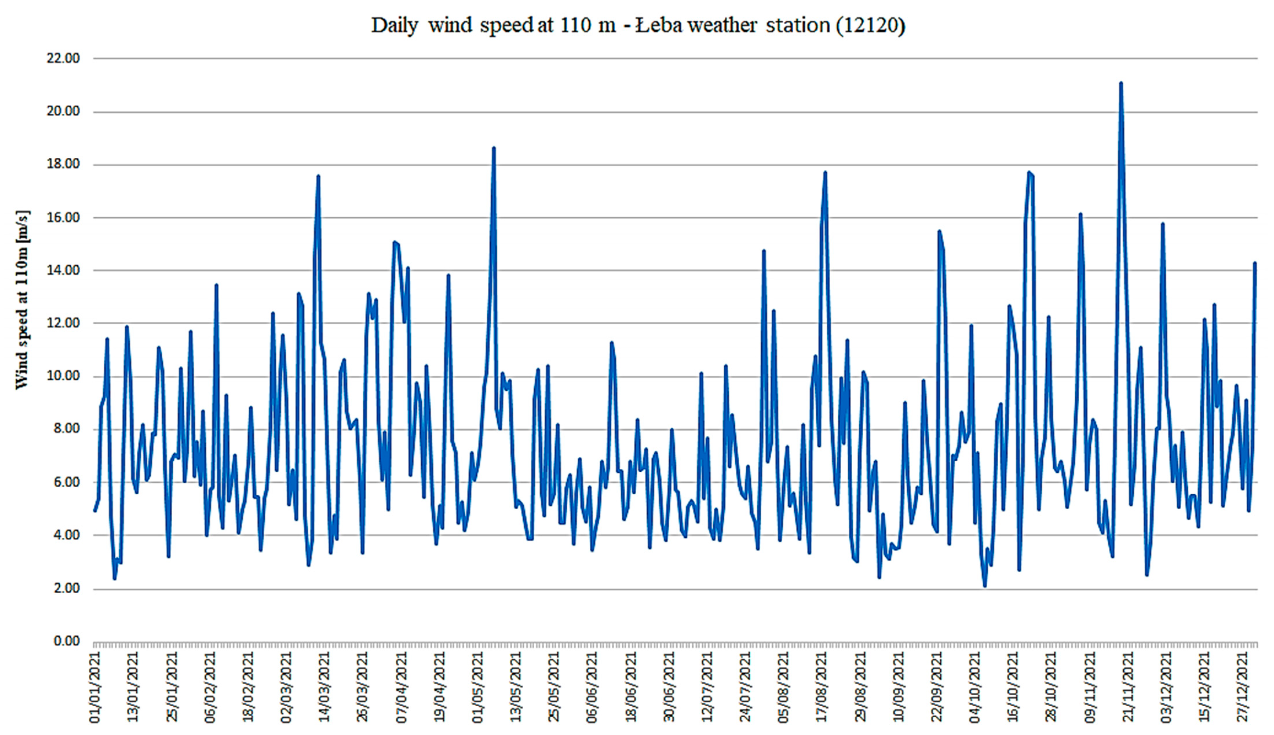
Using hourly wind data from 2021 for the Łeba station, the wind speed at the wind turbine’s height were calculated. The obtained average daily data is shown in the chart below (Figure 5):
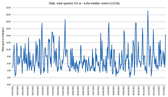
Figure 5.
The daily wind speed at 110 m for 2021 year.
As can be seen from the graph shown, the finest wind conditions are in the fall and in winter months, while a decrease in wind speed can be observed in the summer months. Wind speeds range from 0–max. 29.59 m/s.
Taking into account the predetermined number of wind turbines and their operating parameters and also the losses, the expected daily power produced by the Baltic II wind farm was obtained. The results are shown in Figure 6:
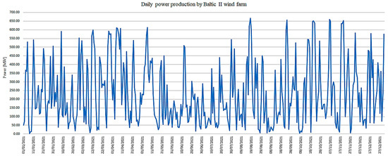
Figure 6.
The hourly power production by Baltic II wind farm.
The achievable power output, after taking into account the previously assumed losses, varies, depending on wind speed, from a maximum value of 670.46 MW to a minimum value of 4.56 MW. Wind turbines are turned off when the wind speed falls below 3 m/s or exceeds 25 m/s. The power allocated to the electrolysis process is 90% of the current capacity of the wind farm.
3.2. Electrolysers and Hydrogen Production
The number of electrolysis system modules was selected for the maximum achievable capacity of 603.42 MW. Thus, an electrolysis system with a total capacity of 600 MW, containing 241 modular units, was adopted. The different modules will be activated based on the amount of electricity supplied by the wind farm. If the delivered power is less than the assumed maximum power, some units will be shut down. Hourly and then monthly average hydrogen production was calculated for predetermined electrolyser parameters and operating conditions. The results are shown in Figure 7:
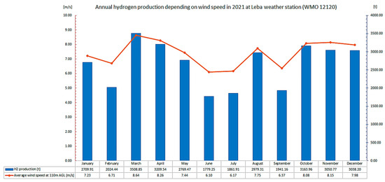
Figure 7.
Annual hydrogen production depending on wind speed in 2021.
As can be seen in the chart shown, the month with the highest average hydrogen production is March with a result of 3508.85 t of hydrogen. The least hydrogen was obtained in June, when the average production was 1779.25 t of hydrogen.
3.3. Desalination and Water Tank System
The volume of water tanks required for the electrolysis process was assumed for an expected maximum hourly hydrogen production of 10.66 tH2/h. The total volume of the tanks for this size should be 161 m3. The maximum calculated value of electricity consumed by the desalination system is 0.56 MWh.
3.4. Hydrogen Compression
The pressure of hydrogen at the electrolyzer’s exhaust is 3 MPa. In order to transport the produced hydrogen through a marine pipeline, it must be compressed to a pressure of 10 MPa. For a maximum hourly hydrogen flow rate of 10,664.25 kgH2/h, the power required for compression is 1.13 MW.
3.5. Hydrogen Pipeline Sizing
For the previously provided assumptions, the diameter of the pipeline delivering the hydrogen produced on the platform to shore was estimated. For the maximum hydrogen flow rate of 33.3 m/s, the design value of the diameter is 320 mm. Finally, a diameter of 350 mm was assumed for the hydrogen transport pipeline.
3.6. Offshore Platform Sizing
Taking into account the maximum possible hydrogen production, it was assumed that a 600 MW offshore hydrogen platform would be constructed. Using the data in [38] and [47] for the predicted 200 MW, 400 MW and 500 MW platforms, calculations were made regarding the dimensions for the various systems of the offshore hydrogen platform. Table 6 summarizes the acquired results:
Table 6.
The 600 MW offshore hydrogen platform sizing based on [38].
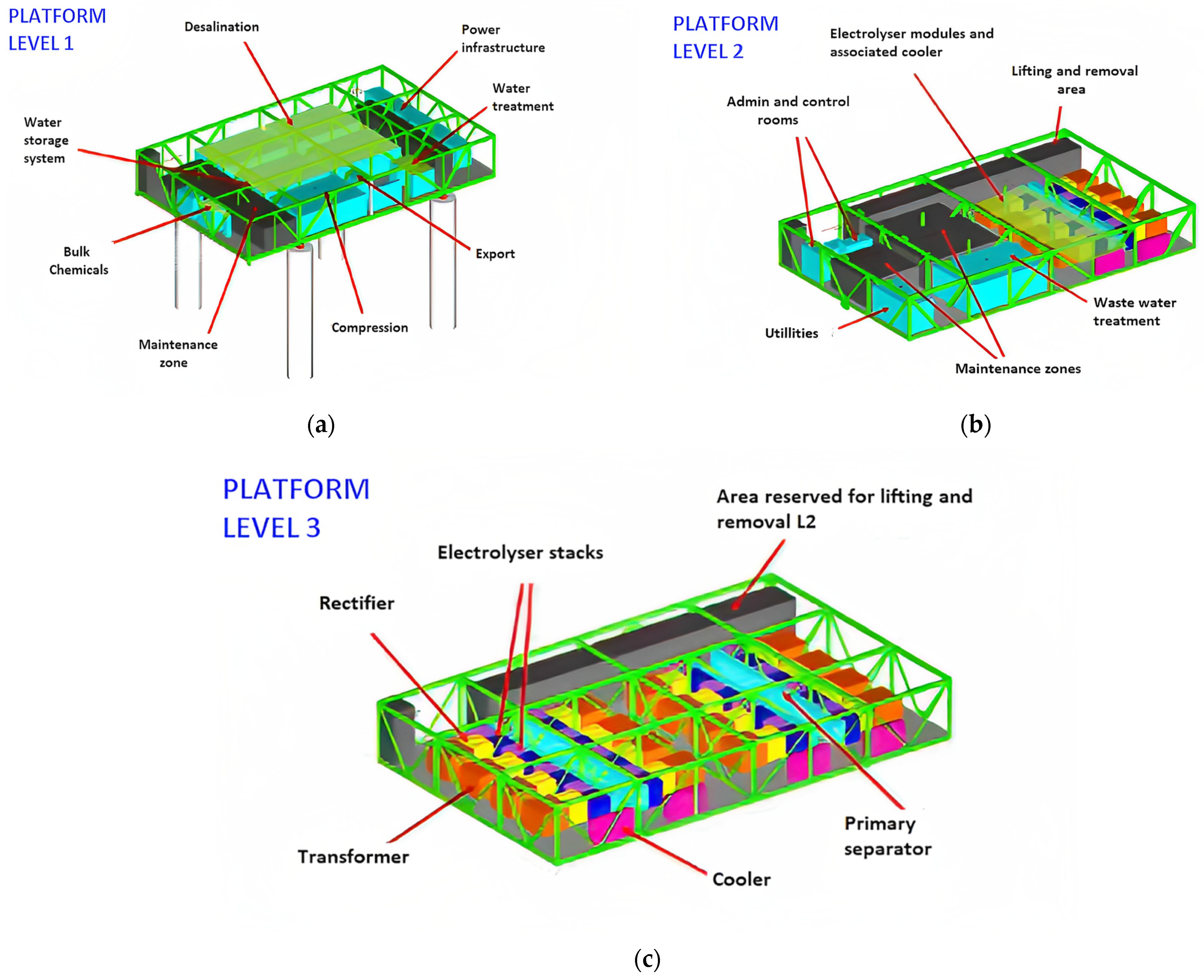
An example visualization of an offshore hydrogen platform modeled in the article is presented in Figure 8, using the schematic from [47]:
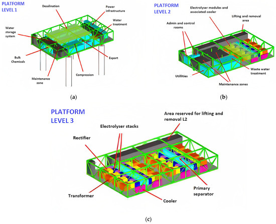
Figure 8.
Scheme of a single 600 MW 3-level offshore hydrogen platform with the particular levels. Source: [47].
4. Discussion and Conclusions
The primary purpose of this research was to present the possibilities of green hydrogen offshore production in the Baltic Sea region, using Poland as a case study. Applying data from the literature on the projected development of offshore wind turbines in the Polish Baltic Sea economic zone, data of wind conditions and the parameters of the systems and equipment chosen for this work, and keeping in mind the assumptions presented earlier, the results of hydrogen production on a centralized dedicated offshore platform were obtained. The proposed centralized offshore hydrogen production systems using the offshore wind energy include not only direct hydrogen production but also delivering surplus energy to onshore in order to balancing grid services. The technology makes use of an offshore electrolyser on a customized platform, where hydrogen is produced, compressed, and piped to shore. Compared to other hydrogen production systems the key benefits of a submarine pipeline for energy transportation in hydrogen form over a submarine electrical cable for direct electrical energy transfer are definitely the lower losses and lower costs than the HVDC cables typically used for power transmission. The main drawbacks of centralized hydrogen system have been the higher cost of additional HVAC cable, and the technical difficulties connected with transferring power to shore. However, when comparing a centralized system to a distributed (in-turbine) hydrogen production system [23,24], where the cost of purchasing and maintaining the equipment for each wind turbine and building a network of pipelines to bring the hydrogen to the collective platform must be taken into account, the centralized system seems much more cost-effective. For onshore hydrogen production, there are significant losses in the transmission of electricity to land, compared to negligible losses for hydrogen transmitted to land. Besides, the main advantage of a centralized offshore system is that there is no use of land and fresh water from the grid for electrolysis, which does not compete with human needs [21].
By analyzing the collected wind data and calculating the hourly output of the wind farm, a PEM electrolyser system from Nel Hydrogen with a total capacity of 600 MW was proposed for hydrogen production. This system was selected based on the maximum achievable power dedicated to the electrolysis process. The power factor for hydrogen production, according to the literature, was 90%. The highest expected hydrogen production was obtained from the winter months, with a maximum monthly average output of 3508.85 t of hydrogen, while a much lower production was obtained in the summer. It can be exempliefied by the results from the month of June with an average production of 1779.25 t of hydrogen. This is directly related to wind conditions in the Baltic Sea, where the best conditions are in the autumn and winter months. Other systems such as the water treatment system and water tanks, the hydrogen compression system and the size of the transport pipeline were selected according to the maximum hourly hydrogen production. The dimensioning of the offshore platform was based on literature data for similar research projects. As for supplying power to the offshore platform during periods of downtime in the wind farm’s electricity production, an additional cable connection to land and a system for temporary shutting down the electrolyser system units were used. This may be a disadvantage, due to the additional cost of constructing the submarine cable as well as due to the possible faster degradation of the electrolysers. To improve this system, the use of a fuel cell as a source of temporary power can be proposed. As mentioned in the article, a major drawback PEM electrolysers is the need to use precious and semi-precious metals as catalysts, which greatly increases electrolysis costs. Pt is the most ideal electrode material for hydrogen generation; nevertheless, its usage is expensive; hence, other possibilities such as employing Pt nanoparticles (to minimize the amount of Pt) or its entire substitution with transition metals such as Ni, Co, and Fe are being investigated in literature [55] The solution may be to use Ni-based alloys, such as Ni-Mo oxides and Ni-Co [56,57] as electrocatalyst materials to reduce costs of electrolysis. Another solution presented in the literature may be the use of the Ni-Mo-Ir-oxide for cathodes [58], the nickel oxide on directly grown carbon nanofibers (CNF-NiO) [59], the Pt40/Ni0.6Mo0.4-oxide electrode [60] and AgPd alloy nanoparticles [61] for improving PEM-type electrolysers. Also using the AEM electrolyser instead of PEM electrolyser could be a convenient solution for improving the presented system. AEM electrolysis may employ low-cost earth metals as electrocatalysts and has the potential for low concentrations of alkaline electrolytes in pure water, making it a large-scale energy storage and clean fuel. It is a highly promising way of producing hydrogen for large-scale applications [55].
The paper focuses only on the technical aspects of the proposed system, without considering costs however, some economic factors of hydrogen generation in Poland should be mentioned. According to estimates [9], the most cost-effective alternative for green hydrogen production in Poland will be to rely on power generated by offshore wind farms. The cost of manufacturing hydrogen is determined by a variety of factors, as method of generation and the energy. Green hydrogen prices are now in the 2.0–7.5 USD/kgH2 range, but are predicted to decline to 0.8–4.2 USD/kgH2 by 2030 and 0.8- 3.5 USD/kgH2 by 2050 [9]. It is achievable by reduction of electrolyser costs (technology advancement and increased scale of manufacture of these devices) and continued reduction in the costs of renewable energy generation [9]. Another point to consider is the concentration of electrical generating in northern Poland. There is a great risk of overloading high-voltage lines when pumping energy into the system from large concentrations of offshore and onshore farms, hence the solution in this circumstance may be hydrogen storage. There are also many issues associated with connecting wind farms to the power grid. In some cases, connectivity is completely denied due to lack of sufficient power infrastructure. In this case, the solution could be to convert the electricity into hydrogen and use it for industrial or transportation purposes [9].
The main constraints encountered during the study were the limited number of wind data from the Baltic Sea region and the calculations performed for the selected site. More wind data and also comparison of other Baltic Sea areas in terms of hydrogen production possibilities should give more accurate results. As suggested earlier, also using AEM electrolysers and comparing their performance to PEM electrolysers in a marine environment could help improve the designed hydrogen production system. Another issue that could affect the results obtained would be comparison of other types of turbines and electrolysers from other companies in terms of their performance. Also important are uncertainties in key parameters that can significantly affect the results obtained. A useful tool in this case would be a sensitivity analysis focusing on parameters such as the distance of the wind farm from the shore and its power output [20]. Due to the limited availability of some of the data, it was abandoned, but this is an area for refining the results in the future.
As an area of future research, several issues are worth considering. According to the findings, more wind energy will be captured during the winter season, when average wind speeds are higher than during the summer. This necessitates greater research into the winter performance of wind turbines, electrolysers, and other systems utilized in hydrogen platforms. Temperature and other environmental variables might affect compressor and cable losses. Including these variances in losses may result in a more complete study outcome. The degradation of the electrolyser components as the effects of wind intermittency is seen as an essential topic to investigate further in order to demonstrate the viability of offshore hydrogen generation. The valuable by-product gained during electrolysis is oxygen, which is about 8 kg of oxygen for 1 kg of hydrogen produced. The obtained oxygen is high pure in quality and can be further utilized for industrial and medical applications. Safety of hydrogen production is also a key issue for future research. The main risks associated with hydrogen production and maintenance of platform equipment and components are related to such phenomena as hydrogen embrittlement, hydrogen permeation, leakages and fire [62]. Another important research area is the integration of hydrogen production with an onshore storage system. Hydrogen can be stored, for example, in salt caverns, pressure tanks or in the form of ammonia. Surplus energy can also be stored in a battery storage system. Lithium-ion battery storage systems, in particular, have many benefits, including increased renewable energy output, cost savings, and environmental sustainability due to lower consumption [63]. Power-to-Gas (P2G) technology is an intriguing possibility, which may be defined as the conversion of power into gas, which can then be exposed to additional distribution, end-use through processing or utilization, and storage for future use and also optimize the hydrogen production [9]. Another solution is metal hydrides using as a hydrogen fuel carrier and hydrogen storage system [64,65,66]. Analysis of hydrogen production capacity, storage and energy utilization system requirements is an extremely important part of Poland’s future hydrogen sector.
Offshore wind energy development can help to decarbonize the national economy while also ensuring the exploitation of Poland’s hydrogen potential. Green hydrogen will be used on a large scale in manufacturing, electricity generation, and transportation in Poland primarily assuming the use of wind energy for its production. The effective planning of maritime areas and allocating a part of wind farms for direct hydrogen production will contribute to Poland’s independence and energy security and will be the chance to the decarbonization of individual sectors of the economy. Hydrogen has several applications, including industry, transportation and also grid balancing services. Green hydrogen’s cost competitiveness is predicted to match that of fossil-fuel-based hydrogen in the near future, thanks to improvements in the wind energy sector and large-scale electrolyser systems.
Author Contributions
Conceptualization, K.L. and M.Ł.; methodology, K.L. and B.L.; software, K.L. and B.L.; validation, K.L. and M.Ł. and B.L.; formal analysis, K.L. and M.Ł.; investigation, K.L. and B.L; resources, K.L. and B.L.; data curation, K.L.; writing—original draft preparation, K.L.; writing—review and editing, K.L. and B.L.; visualization, K.L. and B.L.; supervision, M.Ł.; project administration, K.L. and M.Ł.; funding acquisition, M.Ł. All authors have read and agreed to the published version of the manuscript.
Funding
This research received no external funding.
Data Availability Statement
Not applicable.
Conflicts of Interest
The authors declare no conflict of interest.
References
- Peters, R.; Vaessen, J.; Van der Meer, R. Offshore hydrogen production in the North Sea enables far offshore wind development. In Proceedings of the Offshore Technology Conference, Houston, TX, USA, 4–7 May 2020; pp. 1–14. [Google Scholar]
- Tiwari, P.; Neupane, B.P.; Niraula, D. Prospects of green hydrogen production and supply from offshore renewable energy: Power-to-X pathways. Int. Res. J. Mod. Eng. Technol. Sci. 2021, 3, 307–315. [Google Scholar]
- Baldi, F.; Coraddu, A.; Kalikatzarakis, M.; Jeleňová, D.; Collu, M.; Race, J.; Maréchal, F. Optimisation-based system designs for deep offshore wind farms including power to gas technologies. Appl. Energy 2022, 310, 118540. [Google Scholar] [CrossRef]
- Lucas, T.R.; Ferreira, A.F.; Santos Pereira, R.B.; Alves, M. Hydrogen production from the WindFloat Atlantic offshore wind farm: A techno-economic analysis. Appl. Energy 2022, 310. [Google Scholar] [CrossRef]
- Zaik, K.; Werle, S. Solar and wind energy in Poland as power sources for electrolysis process—A review of studies and experimental methodology. Int. J. Hydrog. Energy 2023, 48, 11628–11639. [Google Scholar] [CrossRef]
- H-BLIX, Offshore Wind Vessel Availability until 2030: Baltic Sea and Polish Perspective. 2022. Available online: http://psew.pl/wp-content/uploads/2022/06/Offshore_wind_vessel_availability_until-2030.pdf (accessed on 24 May 2023).
- Polskie Stowarzyszenie Energetyki Wiatrowej, Potencjał Morskiej Energetyki Wiatrowej w Polsce. Kompleksowa Analiza Możliwości Rozwoju Morskiej Energetyki Wiatrowej w Polskich Obszarach Morskich., Warszawa, 11/2022. Available online: https://konferencja-offshore.pl/wp-content/uploads/2022/11/FarmyMorskie_RaportShort_Prev.pdf (accessed on 23 May 2023).
- Veenstra, A.T.; Schrotenboer, A.H.; Uit het Broek, M.; Ursavas, E. Green Hydrogen Plant: Optimal control strategies for integrated hydrogen storage and power generation wit wind energy. arXiv 2021, arXiv:2108.00530. [Google Scholar] [CrossRef]
- Stori, V. Offshore wind to green hydrogen. Insight from Europe, Clean Energy States Alliance. 2021. Available online: https://www.cesa.org/wp-content/uploads/Offshore-Wind-to-Green-Hydrogen-Insights-from-Europe.pdf (accessed on 23 May 2023).
- Brodacki, D.; Gajowiecki, J.; Hajduk, R.; Kacejko, P.; Kowalski, S.; Matczyńska, E.; Miętkiewicz, R.; Nowakowski, R.; Plaskiewicz, N.; Ruszel, M. Zielony Wodór z OZE w Polsce. Wykorzystanie Energetyki Wiatrowej i PV do Produkcji Zielonego Wodoru Jako Szansa na Realizację Założeń Polityki Klimatyczno-Energetycznej UE w Polsce, Dolnośląski Instytut Studiów Energetycznych, Polskie Stowarzyszenie Energetyki Wiatrowej, Raport 2021. Available online: https://www.psew.pl/wp-content/uploads/2021/12/Raport-Zielony-Wodor-z-OZE-77MB.pdf (accessed on 23 April 2023).
- Bandzul, W. Eneregetyka wiatrowa w Polsce. Elektroenergetyka 2005, 3, 1–28. [Google Scholar]
- Piotrowski, P.; Gryszpanowicz, K. Analiza statystyczna oraz prognozy godzinowej produkcji energii przez elektrownię wiatrową z horyzntem 1 godziny. Elektro Info 2012, 3, 90–95. [Google Scholar]
- Kotowicz, J.; Kwiatek, B. Analiza potencjału wytwórczego farmy wiatrowej. Rynek Energii 2019, 4, 38–47. [Google Scholar]
- Kupecki, J.; Błesznowski, M.; Motyliński, K.; Wierzbicki, M.; Jagielski, S.; Boiski, M.; Krauz, M.; Bąkała, M.; Razumkowa, K.; Skrzypkiewicz, M.; et al. Analiza Potencjału Technologii Wodorowych w Polsce do Roku 2030 z Perspektywą do 2040 Roku, Instytut Energetyki. 2020. Available online: https://klasterwodorowy.pl/images/zdjecia/9_Analiza_potencjalu_technologii_wodorowych_opracowanie.pdf (accessed on 23 April 2023).
- Ligęza, K. Zastosowanie metod elektrolizy wody PEM i SOEC do produkcji wodoru z wykorzystaniem energii z morskich farm wiatrowych. Przemysł Chem. 2021, 100, 754–757. [Google Scholar] [CrossRef]
- Calise, F. Recent Advances in Green Hydrogen Technology. Energies 2022, 15, 5828. [Google Scholar] [CrossRef]
- Sarrias-Mena, R.; Fernández-Ramírez, L.M.; García-Vázquez, C.A.; Jurado, F. Electrolyzer models for hydrogen production from wind energy systems. Int. J. Hydrog. Energy 2015, 40, 2927–2938. [Google Scholar] [CrossRef]
- Liu, Z.; Wang, H.; Zhou, B.; Yang, D.; Li, G.; Yang, B.; Xi, C.; Hu, B. Optimal Operation Strategy for Wind–Hydrogen–Water Power Grids Facing Offshore Wind Power Accommodation. Sustainability 2022, 14, 6871. [Google Scholar] [CrossRef]
- Calado, G.; Castro, R. Hydrogen Production from Offshore Wind Parks: Current Situation and Future Perspectives. Appl. Sci. 2021, 11, 5561. [Google Scholar] [CrossRef]
- Giampieri, A.; Ling-Chin, J.; Roskilly, A.P. Techno-economic assessment of offshore wind-to-hydrogen scenarios: A UK case study. Int. J. Hydrog. Energy 2023, 1. [Google Scholar] [CrossRef]
- Pierozzi, N.; De Bacco, P.; Tascino, C.; Arcangeletti, G.; Tucceri, F.; De Simone, G.; Piazzi, L.; Agogliati, P. Emerging solutions in offshore green hydrogen production and storage. In Proceedings of the Offshore Technology Conference, Houston, TX, USA, 4–7 May 2022; pp. 1–12. [Google Scholar]
- Offshore Hydrogen Production Enables Far-Offshore Wind Deployment. Available online: https://hydrogentechworld.com/offshore-hydrogen-production-enables-far-offshore-wind-deployment (accessed on 23 May 2023).
- Jang, D.; Kim, K.; Kim, K.-H.; Kang, S. Techno-economic analysis and Monte Carlo simulation for green hydrogen production using offshore wind power plant. Energy Convers. Manag. 2022, 263. [Google Scholar] [CrossRef]
- Singlitico, A.; Østergaard, J.; Chatzivasileiadis, S. Onshore, offshore or in-turbine electrolysis? Techno-economic overview of alternative integration designs for green hydrogen production into Offshore Wind Power Hubs. Renew. Sustain. Energy Transit. 2021, 1, 100005. [Google Scholar] [CrossRef]
- Henry, A.; McCallum, C.; McStay, D.; Rooney, D.; Robertson, P.; Foley, A. Analysis of wind to hydrogen production and carbon capture utilisation and storage systems for novel production of chemical energy carriers. J. Clean. Prod. 2022, 354, 131695. [Google Scholar] [CrossRef]
- Walavalkar, A.C. A Comparative Study on Hydrogen Production and Storage Using an Offshore Wind Farm in The Netherlands. Master’s Thesis, Universiteit Utrecht, Utrecht, The Netherlands, 2021. [Google Scholar]
- Song, S.; Lin, H.; Sherman, P.; Yang, X.; Nielsen, C.P.; Chen, X.; McElroy, M.B. Production of hydrogen from offshore wind in China and cost-competitive supply to Japan. Nat. Commun. 2021, 12, 6953. [Google Scholar] [CrossRef]
- Nilsson, M. Offshore Wind Power Co-Operatwd Green Hydrogen and Sea-Water Oxygenation Plant: A Feasibility Case Study for Sweden. Master’s Thesis, Uppsala University, Uppsala, Sweden, 2022. [Google Scholar]
- Danish Energy Agency, Screening of possible hub concepts to integrate offshore wind capacity in the Nort Sea, Report 2022. Available online: https://ens.dk/sites/ens.dk/files/Vindenergi/final_report_-_screening_of_possible_hub_concepts_to_integrate_offshore_wind_capacity_in_the_north_sea.pdf (accessed on 23 May 2023).
- Dinh, V.N.; Leahy, P.; McKeogh, E.; Murphy, J.; Cummins, V. Development of a viability assessment model for hydrogen produc-tion from dedicated offshore wind farms. Int. J. Hydrog. Energy 2021, 46, 24620–24631. [Google Scholar] [CrossRef]
- Bonacina, C.N.; Bordbar Gaskare, N.; Valenti, G. Assessment of offshore liquid hydrogen production from wind power for ship refueling. Int. J. Hydrog. Energy 2022, 47, 1279–1291. [Google Scholar] [CrossRef]
- Ibrahim, O.S.; Singlitico, A.; Proskovics, R.; McDonagh, S.; Desmond, C.; Murphy, J.D. Dedicated large-scale floating offshore wind to hydrogen: Assessing design variables in proposed typologies. Renew. Sustain. Energy Rev. 2022, 160, 112310. [Google Scholar] [CrossRef]
- Akyuz, E.; Oktay, Z.; Dincer, I. Energy Analysis of Hydrogen Production from a Hybrid Wind Turbine-Electrolyzer System. In Progress in Exergy, Energy, and the Environment; Springer: Berlin/Heidelberg, Germany, 2014. [Google Scholar] [CrossRef]
- Egeland-Eriksen, T.; Flatgård, J.J.; Ulleberg, Ø.; Sartori, S. Simulating offshore hydrogen production via PEM electrolysis using real power production data from a 2.3 MW floating offshore wind turbine. Int. J. Hydrog. Energy 2023, 48, 28712–28732. [Google Scholar] [CrossRef]
- Cho, Y.; Lee, S.; Lim, J.; Lee, J. Economic Analysis of P2G Green Hydrogen Generated by Existing Wind Turbines on Jeju Island. Energies 2022, 15, 9317. [Google Scholar] [CrossRef]
- Cheng, C.; Hughes, L. The role for offshore wind power in renewable hydrogen product in Australia. J. Clean. Prod. 2023, 391, 136223. [Google Scholar] [CrossRef]
- Jang, D.; Kim, J.; Kim, D.; Han, W.-B.; Kang, S. Techno-economic analysis and Monte Carlo simulation of green hydrogen production technology through various water electrolysis technologies. Energy Convers. Manag. 2022, 258, 115499. [Google Scholar] [CrossRef]
- Sæbø, A.O.; Trøen, T.L.; Sydness, G.S.; Lerøy Schaefer, J.M.; Baardsen, A.H.; Notkevich, L.; Fosse, V.; Guldbrandsen Frøysa, K.; Solbrekke, I.M.; Oltedal, V.M. “Optimal utnyttelse av energi fra havvind i Sørlige Nordsjø II,” Greenstat, Bergen. 2021. Available online: https://www.uib.no/sites/w3.uib.no/files/attachments/optimal_utnyttelse_av_energi_fra_havvind_i_sorlige_nordsjo_ii-compressed.pdf (accessed on 20 April 2023).
- Lundvall, N. Modelling Hydrogen Production from Offshore Wind Parks. A Techno-Economic Analysis of Dedicated Hydrogen Production. Master’s Thesis, Mälardalen University, Västerås, Sweden, 2022. [Google Scholar]
- MFW Bałtyk II Sp. z o.o. Available online: https://www.ure.gov.pl/pl/oze/mfw/plany/9458,MFW-Baltyk-II-Sp-z-oo.html (accessed on 23 May 2023).
- Grupa Doradcza SMDI, Morska Farma Wiatrowa Bałtyk Środkowy II. Raport o Oddziaływaniu na Środowisko. Tom IV, Warszawa. 2015. Available online: https://portalgis.gdansk.rdos.gov.pl/morskafarmawiatrowa-BaltykSrodkowyII/RAPORT/Tom%20IV_Ocena%20oddzialywania/Sekcja%203_OOS%20bentos/BSII_TIV_S3_bentos_ost.pdf (accessed on 20 April 2023).
- Przyszłość Morskiej Energetyki Wiatrowej w Polsce. Available online: http://psew.pl/wp-content/uploads/2019/06/Przysz%C5%82o%C5%9B%C4%87-morskiej-energetyki-wiatrowej-w-Polsce-raport.pdf (accessed on 23 May 2023).
- 12120 Łeba Weather Station. Available online: https://www.ogimet.com/display_synops.php?lang=en&tipo=ALL&ord=REV&nil=SI&fmt=html&anof=2023&mesf=06&dayf=19&horaf=11&minf=54&ano=2023&mes=06&day=18&hora=11&min=54&lugar=12120 (accessed on 22 February 2023).
- Bodbar Gaskare, N. Techno-Economic Analysis of the Production of Green Liquid Hydrogen on Offshore Platforms from Wind Energy to Refuel Ships. Master’s Thesis, Politecnico di Milano, Milan, Italy, 2021. [Google Scholar]
- Wind Turbine V236-15.0 MW. Available online: https://www.vestas.com/en/products/offshore/V236-15MW (accessed on 22 April 2023).
- Teien, M.A. Combining Offshore Power and Hydrogen Production. Master’s Thesis, Norwegian University of Science and Technology, Trondheim, Norway, 2022. [Google Scholar]
- North Sea Wind Power Hub. Available online: https://northseawindpowerhub.eu/sites/northseawindpowerhub.eu/files/media/document/NSWPH_Grid-integrated%20offshore%20Power-to-Gas_Discussion%20paper%20%231.pdf (accessed on 24 May 2023).
- M Series Containerized PEM. Available online: https://nelhydrogen.com/wp-content/uploads/2021/01/M-Series-Containerized-Spec-Sheet-Rev-F.pdf (accessed on 24 May 2023).
- Hydrogen Generators. Available online: https://nelhydrogen.com/wp-content/uploads/2022/06/High-Purity-Brochure-Rev-J-Single-Pages.pdf (accessed on 24 May 2023).
- Baardsen Høines, A. A Concept Study on Offshore Floating Hydrogen Production, Storage and Offloading. Master’s Thesis, University of Bergen, Bergen, Norway, 2022. [Google Scholar]
- Odongo, C. Feasibility Study of Hydrogen Production from Wind Energy in Narvik. Master Thesis, The Arctic University of Norway, Tromsø, Norway, 2021. [Google Scholar]
- Vestrheim, M. Offshore Hydrogen Production from Floating Offshore Wind—A Study of Unitech Zefyros. Master’s Thesis, University of Bergen, Bergen, Norway, 2022. [Google Scholar]
- Alvestad, K. Combined Hydrogen and Offshore Wind Production. Design and Market Value. Master’s Thesis, University of Oslo, Oslo, Norway, 2022. [Google Scholar]
- Włodek, T.; Łaciak, M.; Kurowska, K.; Węgrzyn, Ł. Thermodynamic analysis of hydrogen pipeline transportation—Selected aspects. AGH Drill. Oil Gas 2016, 33, 379–395. [Google Scholar] [CrossRef]
- Seamless Pipe Sizes. Available online: https://www.nan-steel.com/news/seamless-steel-pipe-sizes.html (accessed on 24 May 2023).
- Gomez Vidales, A.; Millan, N.C.; Bock, C. Modeling of anion exchange membrane water electrolyzers: The influence of operating parameters. Chem. Eng. Res. Des. 2023, 194, 636–648. [Google Scholar] [CrossRef]
- Gomez Vidales, A.; Omanovic, S. Evaluation of nickel-molybdenum-oxides as cathodes for hydrogen evolution by water electrolysis in acidic, alkaline, and neutral media. Electrochim. Acta 2018, 262, 115–123. [Google Scholar] [CrossRef]
- Gomez Vidales, A.; Choi, K.; Omanovic, S. Nickel-cobalt-oxide cathodes for hydrogen production by water electrolysis in acidic and alkaline media. Int. J. Hydrog. Energy 2018, 43, 12917–12928. [Google Scholar] [CrossRef]
- Gomez Vidales, A.; Dam-Quang, L.; Hong, A.; Omanovic, S. The influence of addition of iridium-oxide to nickel-molybdenum-oxide cathodes on the electrocatalytic activity towards hydrogen evolution in acidic medium and on the cathode deactivation resistance. Electrochim. Acta 2019, 302, 198–206. [Google Scholar] [CrossRef]
- Vidales, A.G.; Sridhar, D.; Meunier, J.-L.; Omanovic, S. Nickel oxide on directly grown carbon nanofibers for energy storage applications. J. Appl. Electrochem. 2020, 50, 1217–1229. [Google Scholar] [CrossRef]
- Gomez Vidales, A.; Semai, M. Platinum nanoparticles supported on nickel-molybdenum-oxide for efficient hydrogen production via acidic water electrolysis. J. Mol. Struct. 2023, 1290, 135956. [Google Scholar] [CrossRef]
- Wan, C.; Zhou, L.; Xu, S.; Jin, B.; Ge, X.; Qian, X.; Xu, L.; Chen, F.; Zhan, X.; Yang, Y.; et al. Defect engineered mesoporous graphitic carbon nitride modified with AgPd nanoparticles for enhanced photocatalytic hydrogen evolution from formic acid. Chem. Eng. J. 2022, 429, 132388. [Google Scholar] [CrossRef]
- Abohamzeh, E.; Salehi, F.; Sheikholeslami, M.; Abbassi, R.; Khan, F. Review of hydrogen safety during storage, transmission, and applications processes. J. Loss Prev. Process Ind. 2021, 72, 104569. [Google Scholar] [CrossRef]
- Sayed, E.T.; Olabi, A.G.; Alami, A.H.; Radwan, A.; Mdallal, A.; Rezk, A.; Abdelkareem, M.A. Renewable Energy and Energy Storage Systems. Energies 2023, 16, 1415. [Google Scholar] [CrossRef]
- Yaxiong, W.; Shunbin, Z.; Fengchun, S. Research Progress in Vehicular High Mass Density Solid Hydrogen Storage Materials. Chin. J. Rare Met. 2022, 46, 796–812. [Google Scholar]
- Zhang, L.; Nyahuma, F.M.; Zhang, H.; Cheng, C.; Zheng, J.; Wu, F.; Chen, L. Metal organic framework supported niobium pentoxide nanoparticles with exceptional catalytic effect on hydrogen storage behavior of MgH2. Green Energy Environ. 2023, 2, 589–600. [Google Scholar] [CrossRef]


Disclaimer/Publisher’s Note: The statements, opinions and data contained in all publications are solely those of the individual author(s) and contributor(s) and not of MDPI and/or the editor(s). MDPI and/or the editor(s) disclaim responsibility for any injury to people or property resulting from any ideas, methods, instructions or products referred to in the content. |
© 2023 by the authors. Licensee MDPI, Basel, Switzerland. This article is an open access article distributed under the terms and conditions of the Creative Commons Attribution (CC BY) license (https://creativecommons.org/licenses/by/4.0/).