Article

Numerical Investigation on the Yield Pillar Bearing Capacity under the Two-End-Type Cable Reinforcement

1
School of Mines, China University of Mining and Technology, Xuzhou 221116, China
2
Key Laboratory of Deep Coal Resource Mining (CUMT), Ministry of Education, Xuzhou 221116, China
*
Author to whom correspondence should be addressed.
Energies 2023, 16(18), 6418; https://doi.org/10.3390/en16186418
Submission received: 4 August 2023 / Revised: 25 August 2023 / Accepted: 2 September 2023 / Published: 5 September 2023
(This article belongs to the Special Issue Advances in Coal and Water Co-mining)

Abstract

:
For underground coal mining techniques such as gob-side entry retaining (GER) or gob-side entry driving (GED), the stability of yield pillars is paramount. A well-designed yield pillar aims to withstand mining-induced stresses. This study delves into the impact of bi-terminal cable support on the stability of such pillars. Utilizing 30 distinct numerical models, each with varying pillar width/height (w/h) ratios and diverse cable support methodologies, our findings suggest an upward trend in both peak and residual strength in response to heightened support strength. Notably, pillars with a wider configuration exhibited a more pronounced increase in peak strength compared to their narrower counterparts, while the latter showcased a more pronounced residual strength enhancement. Additionally, the residual/peak strength ratio was smaller in narrower pillars and increased with the increase in the cable support strength. In view of the surrounding rock mass’s support stress distribution, numerical modelling was adopted to analyze the underlying support mechanism. The results showed the support stress zones extended farther on both sides of pillars with the decrease in the row spacing, which made the radial stresses rise effectively and ameliorated the coal pillar’s stress state. Finally, with the 8311 operation advancing towards the station, the deformation amplitude of the coal pillar was only 2.28%, and the stability of the coal pillar was effectively maintained.

1. Introduction

Traditional dual-roadway excavation practices often involve retaining a coal pillar, generally between 15 to 30 m, between neighboring mining sections. This is primarily to ensure systematic backfill of the extraction area and smooth continuation of mining processes. Yet, this method results in notable coal wastage. As we venture deeper into mining, these broader coal pillars become focal points of stress, leading to the potential for coal-pillar-centric dynamic ground pressure incidents, presenting significant operational safety concerns [1]. With advancements in pillar-free mining methods, there is a rising inclination among coal mines towards the gob-side entry driving (GED) approach. This strategy is centered around maintaining slender coal pillars. Drawing from the understanding of internal and external stress zones emerging after lateral roof breakage, the GED method situates the passage for the succeeding extraction area close to the low-stress vicinity adjacent to the previously excavated goaf, while keeping coal pillars with widths of about 3–5 m. This innovative method promotes superior coal extraction efficiency, reduces resource squandering, and substantially decreases the hazards linked to coal-pillar-centric dynamic ground pressures, as supported by contemporary studies [2,3].
Despite the effective use of the gob-side entry driving (GED) technique that retains slender coal pillars, several challenges remain. One significant concern is the need to delay excavation of roadways in subsequent mining areas until the overlying strata in the neighboring goaf stabilize, in order to counteract dynamic pressures. This delay spans an extended period, typically 6 to 8 months, post-extraction. Such postponements present substantial hurdles to maintaining mining operations seamlessly, especially during transitional stages. The magnitude of this challenge amplifies with the increasing mining operations observed in modern mines, thus acting as a hindrance to optimal resource utilization [4]. Another point of contention lies in the fact that the gob-side entry roadway’s close proximity to the goaf means that even when small coal pillars reside within low-stress zones, they often bear lateral pressures exceeding their capacities. This, in turn, makes these slender pillars prone to deformation and potential collapse. A significant obstacle to bolstering these pillars’ structural resilience is the lack of robust mechanical links between the primary support structures, such as anchor rods, on both its sides [5]. Excessive drilling for these anchor rods could erode the pillar’s structural integrity, paving the way for widespread instability across its entire breadth [6]. Hence, it is hardly surprising that most slender pillars in current GED operations display pronounced deformation patterns, often manifested as “bulging” and coal wall slippages, culminating in considerable roadway deformations. Such deformations can disrupt the ventilation within the goaf, escalating to grave scenarios, including fires.
In addressing the aforementioned challenges, the academic community has delved deeply into solutions. Su et al. [7] scrutinized the dynamics of stress and deformation in surrounding rock across multiple excavation iterations. Their findings champion the use of high-prestressed strong anchor rods and comprehensive cable supports as effective tools in mitigating deformation in gob-side entry paths. Meanwhile, Wang et al. [8] amalgamated various methodologies—from field investigations to laboratory tests, from numerical models to theoretical insights—to discern the inconsistent deformation mechanisms in slim coal pillar pathways. Their research indicates that maintaining a 6 m breadth for coal pillars optimizes outcomes. Moreover, they introduced a multifaceted support mechanism encompassing “anchor cables, grouting, and single post”, which they integrated into real-world engineering endeavors. On another front, Xie et al. [9] formulated the plasticity factor P, a metric to gauge the progression of plastic zones in varying sections of the roadway’s enclosing rock. Their method fine-tuned the evaluation of the bearing aptitude of surrounding rocks. By coupling an 8 m coal pillar with contemporary anchor rod and cable methodologies, Xie adeptly managed the encompassing rock’s performance in the context of leftover coal pillars. Li et al. [10] showcased a cutting-edge technique for ultra-thick coal strata using narrow pillars for gob-side entry. To overcome roadway control predicaments, Li amalgamated a plethora of support strategies ranging from high-strength anchor rod cables to grouting within the slender coal pillar and nearby goaf sectors. Gong et al. [11] harnessed borehole imagery to glean insights into thin coal pillars under unstable overburden, especially concerning comprehensive discharge. They devised a strategic roof blasting method to instigate targeted fractures, mitigating pressure around the goaf. This led to the inception of a comprehensive rock control tech-system, encapsulating elements such as “advanced pre-cracking”, “roof reinforcement”, and “temporary lagging support”, all pivotal for controlling the top plate in vast mining voids. Some academicians have even advocated for the “extended advancing distance method from the mining face”, setting the groundwork for parameters including various coal pillar dimensions [12,13]. Finally, Wang and team [14] contrived models to analyze the overlying rock and coal pillar dynamics under mining scenarios. Factors, including roof span and hardness, were considered vital in assessing the stability of the roadway’s lateral segment. A strategic combination of deep-hole blasting for pressure alleviation and the use of specialized grout bolts can lead to optimized coal pillar widths ranging from 4 to 15 m, thereby bolstering the stability of roadways and pillars.
The inherent mechanical characteristics of coal, being notably brittle, play a pivotal role in determining both the failure mechanism and stability of pillars. Liu et al. [15] deduced from their studies that the uniaxial compressive strength of coal samples fluctuates between 10 and 40 MPa. Interestingly, a clear decline in strength was evident as the sample size increased. One salient feature of coal is its pronounced strain-softening behavior. This perspective is echoed by Liu and Shen [16] who discerned that the failure of coal samples can be compartmentalized into three distinct regions: the residual, strain-softening, and elastic areas. From a practical standpoint, a pillar undergoes a sequence of phases prior to failure, encompassing elasticity, followed by plastic-softening, and finally reaching the residual phase. In parallel studies, Han et al. [17], Ren et al. [18], and Yue et al. [19] utilized numerical models to reveal a significant correlation between a pillar’s width-to-height (w/h) ratio and its inherent strength. Furthermore, empirical evidence suggests that adopting an appropriate support framework can substantially augment the load-bearing potential of coal pillars [20,21].
Historical studies have highlighted a few pivotal considerations regarding coal pillars. Firstly, the significance of evaluating artificial support in the design phase of a coal pillar cannot be understated, as it directly impacts the pillar’s stability. Secondly, traditional research methods predominantly utilized conventional cables and bolts for yield pillar reinforcement; however, the superior performance of the two-end-type cable was evident in specific trials [22]. Lastly, a comprehensive understanding of the mechanism behind the two-end-type cable support is yet to be achieved. To address these issues, our current research employed the FLAC3D numerical code for analysis, aiming to probe the potential improvements when using cables on pillars and to decipher the role of artificial support in bolstering pillar stability. This computational approach offers a controlled environment, insulating the experimental setup from extraneous influences, which in turn, aids in honing insights under designated conditions, enabling a deeper understanding of inherent mechanisms.
Commencing with the engineering geological conditions of Tashan Coal Mine, 30 numerical models were crafted within FLAC3D, ensuring meticulous calibration of the constitutive model parameters of the surrounding rock. Subsequent phases delved into the impact of the two-end-type cable support design on the peak and residual strengths of the coal pillar. Emphasis was also placed on comprehending the mechanism of this design through stress distribution patterns. The culmination of this endeavor was an on-site industrial verification of the efficacy of this cable reinforcement method. The insights garnered from this research not only bolster the theoretical foundations of coal pillar reinforcement using the two-end-type cable but also offer pragmatic guidelines for real-world applications.

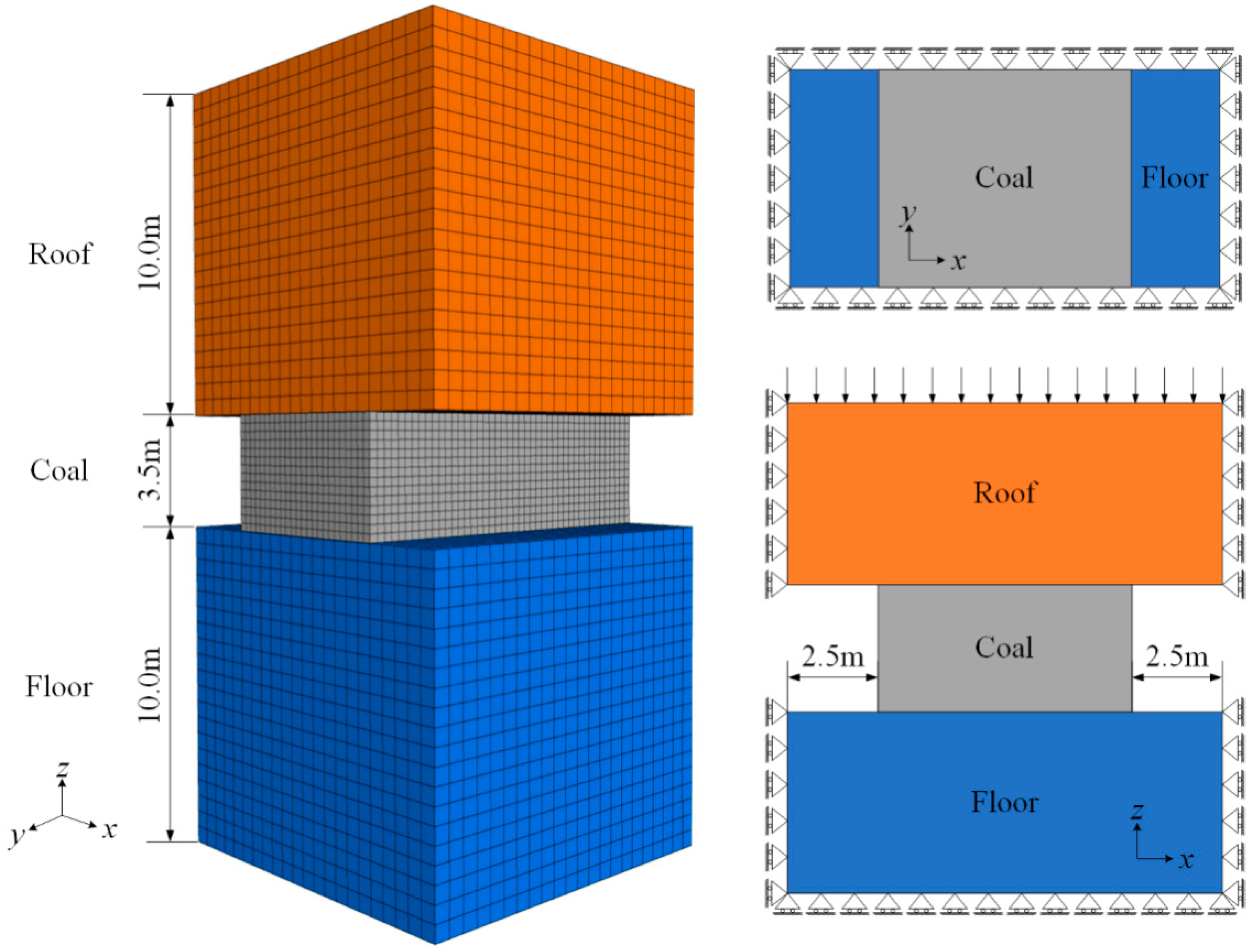
2. Establishment of the Numerical Model

The coal yield pillars’ support design is one of the most important factors affecting mining roadway stability. It is very important to delve into the support rule of yield pillars to construct an effective and safe support strategy to keep mining roadways stable. For this investigation, we used data extracted from the 8311 panel situated in Tashan coal mine, China. Located at a depth close to 510 m, the specific longwall panel focuses on coal seam #4, characterized by a thickness of approximately 3.5 m and a subtle average dip angle of about 4°. As shown in Figure 1, judging from the drilling records, the immediate roof is siltstone measuring 3.3 m thick on average, the main roof is medium sandstone measuring 11.1 m thick on average, the immediate floor was mudstone measuring 3.3 m thick on average, and the major floor was sandy mudstone measuring 6.9 m thick on average. The roof is very solid. The working face adopts a double roadway framework, but the pillar measures only 6 m in width.

2.1. Simulation Methodology

Using the FLAC3D three-dimensional simulation platform, we set out to assess the bearing capacity of coal yield pillars when subjected to cable reinforcement. The stability of these coal pillars, which play a pivotal role in the redistribution of abutment load, hinges on the mechanical attributes of the encompassing rock and the geometry of the roof-coal-floor assembly. As such, we constructed a numerical representation encapsulating the roof, the coal pillar, and the floor to delve into the deterioration processes affecting coal pillars. Refer to Figure 2 for a detailed view of the pillar model’s grid structure and the designated boundary conditions. We varied the pillar’s width to represent pillars with w/h ratios ranging between 1.5 and 2.5.
For the model in consideration, the coal pillar’s height was set at 4.0 m, with the roof and floor each measuring 10 m. The grid specifications for the pillar zones were determined as 0.25 m in all three dimensions. Meanwhile, the rock zones were dimensioned at 0.5 m cubically. Opting for a full pillar model approach, this configuration closely mirrors the lab sample tests, rather than employing a fractional pillar based on symmetry. Mirroring the conditions one would expect in a laboratory setting, displacement constraints were imposed on the model’s four sides and its base. The roof’s upper surface had a steady velocity of 10−5 m/s, ensuring both the roof and floor had restricted horizontal movements.
Concurrently, meticulous attention was given to the rock mass’s physical and mechanical attributes to facilitate an accurate underground simulation. The Mohr–Coulomb criterion was implemented for replicating the roof and floor behavior. Parameters guiding the rock mass were derived both from lab tests on samples from Tashan coal mine and an established parameter translation technique. For the coal pillar’s representation, the strain-softening variant of the Mohr–Coulomb model was adopted. This approach adjusted the cohesion, friction, and dilation angles based on the degree of plastic strain, aligning with the strain-softening traits observed in coal pillars. Calibration of this model was achieved through the iterative process, referencing an empirical strength equation tailored for coal pillars. Lastly, to account for the crucial role of rock–coal junctions in determining coal pillar load-bearing abilities, interface elements represented coal–rock contact points. These elements drew from contemporary studies on coal pillar design.
The methodology for the simulation encompasses the following sequential steps: (1) Initialization involves grid operation followed by the configuration of boundary conditions. (2) Initially, the pillar material was treated as elastic. It was then brought to a balanced state to generate the inherent stresses present in situ. (3) Subsequently, the pillar was defined using a calibrated strain-softening model. Concurrently, roadways were introduced on either side of the pillar. (4) For bolstering pillar support, a cable was affixed at both ends. (5) Lastly, to induce a vertical load, a persistent velocity of 10 5 m/s was exerted atop the roof.

2.2. Calibration of the Simulation Parameters

Table 1 illustrates that with an already proposed method of parameter conversion, the laboratory estimation of test specimens was adopted to obtain the physical as well as mechanical rock mass parameters [23,24].
Additionally, former research shows the coal–rock interface with its properties is crucial for the coal pillar bearing capacity. In this research, the interface was adopted to simulate the connections between the surrounding rocks and the coal. Table 1 displays the interface elements’ material properties selected from recent studies on coal pillar design [25,26].

2.3. Parameters for the Yield Pillar

Based on empirical equations that determine the strength of slender coal pillars, a refined numerical pillar model was established. This approach aimed to ensure that the parameters fed into the strain-softening Mohr–Coulomb model were both pertinent and practical, as highlighted in references [27,28]. This constitutive model allows for the parameters such as cohesive strength and internal friction angle of model elements to weaken as the plastic shear strain of the elements increases. Ultimately, this achieves the simulation of mechanical behavior where strength gradually diminishes and plastic deformation occurs during the loading process.
The empirical equation takes the pillar size’s effect on its strength, coal body strength, and coal seam’s buried depth into account. The empirical equation is
σ p = 0.27 σ c h 0.36 + H / 250 + 1 w / h 1
where σ p is coal pillar strength (MPa); σ c is coal intact strength (MPa); H is coal seam’s buried depth (m); and w and h are coal pillar’s width and height (m), respectively.
Table 2 showcases the selected softening rates and final mechanical parameters employed in our study. Figure 3 delineates a comparative analysis between strengths deduced from the coal pillar strength equation and those determined through numerical simulations. The plotted curve symbolizes strengths as per the coal pillar strength formula, while the individual points highlight strengths derived from simulations. Employing the least squares method, a correlation coefficient of 0.977 was derived, pointing to an impressive alignment between empirical predictions and simulation outcomes. Thus, the parameters in Table 2 are suitable to illustrate the strain-softening attributes of the coal pillar. At a plastic shear strain of 0.005%, both cohesion and friction angle dropped to 1.97 MPa and 22°, respectively. With a plastic strain at 0.5%, they further diminished to 0.66 MPa and 18°, respectively. Beyond this point, both cohesion and friction angle plateaued at values of 0.66 MPa and 18°, respectively.

3. Numerical Modelling of Two-Ended Cables

During the numerical simulation, the pillar’s height remained at 3.4 m. And to model pillars with w/h ratios from 1.5 to 2.5, its widths shifted from 5 to 9 m. To explore the two-end-type cable reinforcement on narrow pillars, five support strategies could be used in the model and then distinguished from the original pillar without strengthening support. In the five support designs, a diameter of 21.8 mm prestressed cable was adopted, with a 1.5 m cable spacing and a 250 kN pretension. The cables’ tensile strength was 500 kN and its row spacing usually ranges from 1.5 m to 2.5 m. However, as the row spacing rose, the cable’s strengthening effect imposed on the pillar strength was weakened, resulting in large discreteness during the simulation. Therefore, the spaces between rows alongside the entry strike direction were set at 500, 750, 1000, 1250, and 1500 mm. Table 3 presents the pillar strength results for all of the cases used in this study.

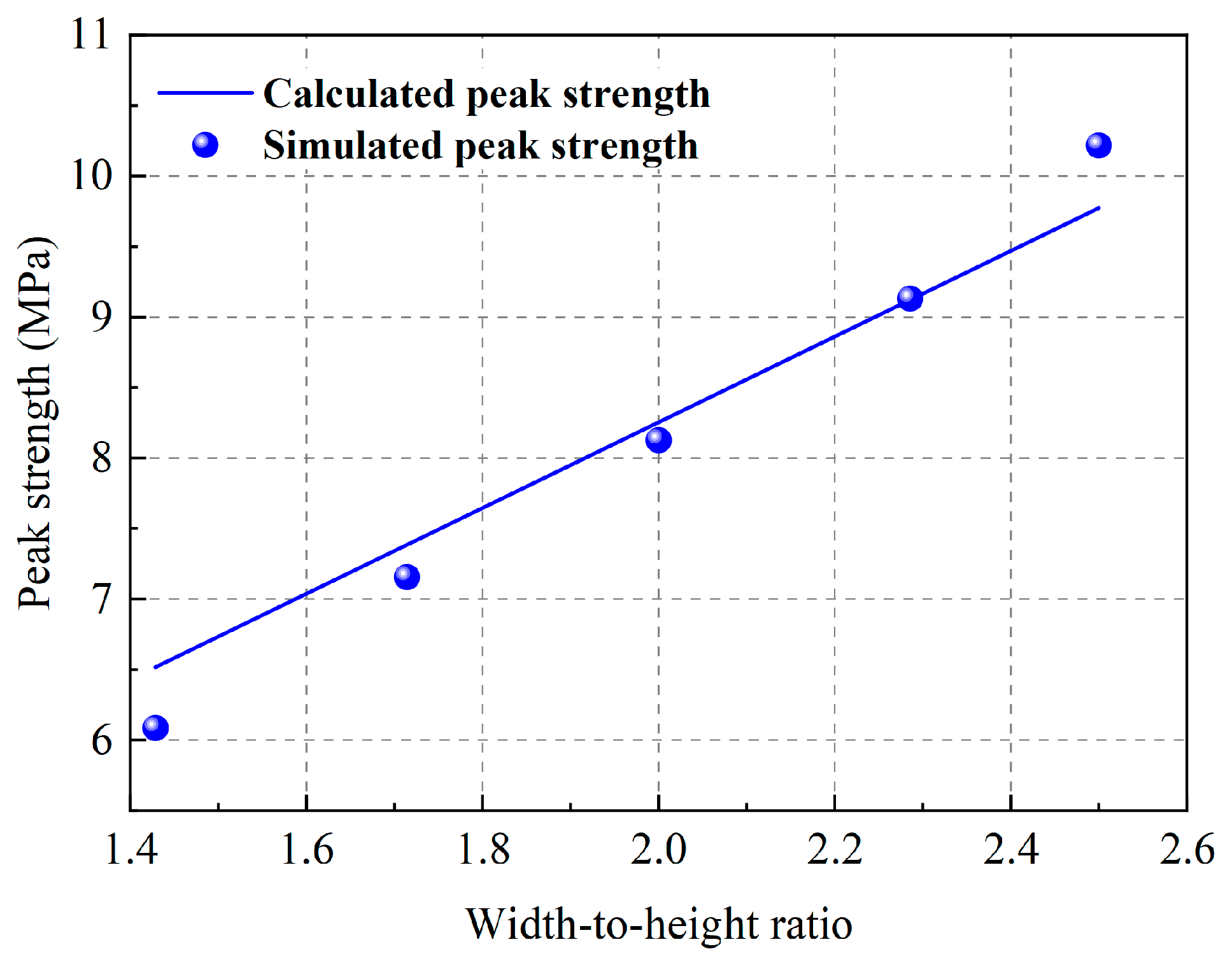
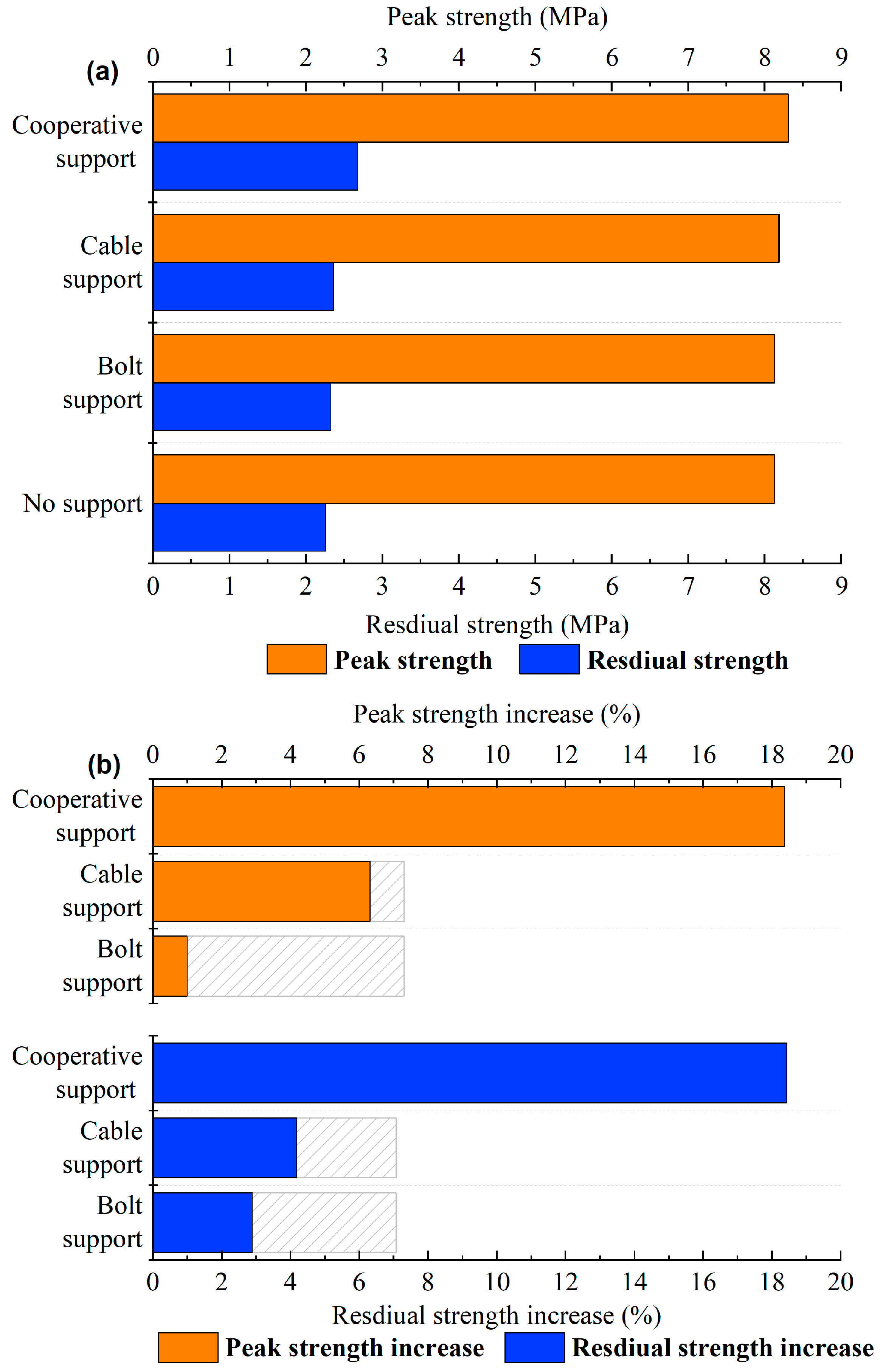
3.1. Relations between Peak Strength and Two-Ended Cables

Figure 4a shows the relation between the cable support strength and peak strength, while Figure 4b presents the relation between the pillar width and peak strength.
The modelling results show peak strength rose as cable support strength increased. This phenomenon can be explained by the pillar’s yield mechanism. The pillar was constrained by the cable to expand to free space, and the pillar’s bearing capacity was ameliorated. Meanwhile, the percentage increase in peak strength for wider pillars exceeded that for narrow pillars. For instance, the modelling predicted that the peak strength of a 9.0 m wide pillar would increase by 4.37% with a cable support strength of 0.60 MPa, while the peak strength of a 5.0 m wide pillar would increase by 2.91% under the same cable support strength. As shown in Figure 4b, when the support strength was below 0.30 MPa, the predicted rising in pillar strength was less sensitive to the w/h ratio or pillar width. When support strengths were over 0.30 MPa, the strengthening effect of cables on peak strength increased rapidly with pillar width. The modelling results suggest that the cable more so affected the wider coal pillar’s peak strength.

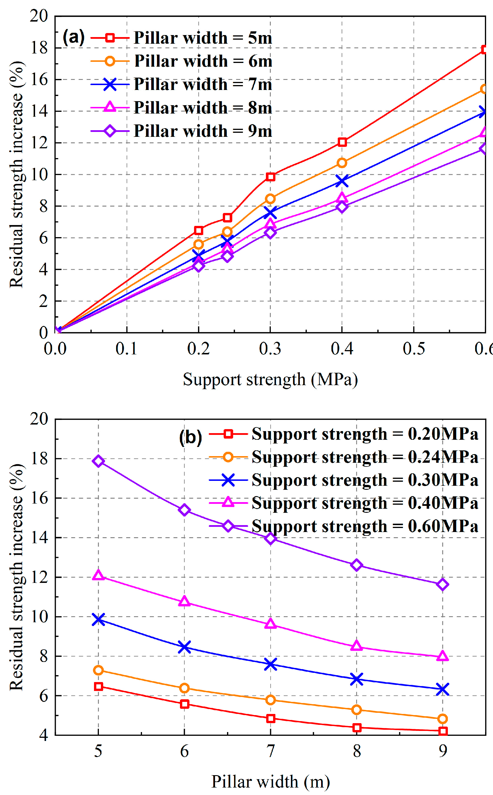
3.2. Relations between Residual Strength and Two-Ended Cables

Figure 5a displays the relation between residual strength and cable support strength, while Figure 5b presents the relation between pillar width and residual strength.
The modelling results show that the cable provided higher restriction to the coal pillar with increasing cable support strength. As a result, the coal pillar’s residual strength improved. However, different from the peak strength, the percentage increase in residual strength for narrower pillars exceeded that for wider pillars. For instance, the modelling estimated that the residual strength of a 9.0 m wide pillar would increase by 11.63% with a cable support strength of 0.60 MPa, while the residual strength of a 5.0 m wide pillar would increase by 17.88% under the same cable support design. As shown in Figure 5b, when the support strength was below 0.30 MPa, the residual strength rising became less sensitive to w/h ratio or pillar width. When support strengths were over 0.30 MPa, the strengthening effect of cables on residual strength reduced rapidly with pillar width. The modelling results suggest that the cable imposes a greater effect on the narrower coal pillars’ residual strength.

3.3. Comparison of the Strengthening Effect of the Peak Strength and Residual Strength of Pillars under Two-End-Type Anchoring

As shown in Table 3, wider coal pillars were always stronger than narrower coal pillars. Meanwhile, as the coal pillar width increased, the ratio of residual/peak strength increased and the strain-softening property decreased, leading to the gradual failure of the wider pillars. In contrast, the narrower pillar failure can be more violent. Additionally, as the support strength increased, the ratio of residual/peak strength increased, revealing that the cables can ameliorate the failure features effectively and keep the pillars from violent failure.
Figure 6 shows that as the pillar width was maintained, the increase in peak strength and residual strength increased gradually with support strength. Meanwhile, when the support design was maintained, the increase in peak strength increased with pillar width; however, the increase in residual strength showed the opposite law. As the support strength turned to 0.60 MPa, the pillar width increased, ranging from 5.0 to 9.0 m; the peak strength increased from 2.91% to 4.37%; and the increase in residual strength decreased from 17.88% to 11.63%.
The pillar residual strength has a critical effect on redistributing stress during longwall mining, and a smaller residual strength of the coal pillar means that more load will be transferred to the surrounding working face [29]. Judging from the simulation results, for the narrower pillars after cable support strengthening, the coal resource recovery can be ameliorated, and stress concentration inside the pillar can be cut down to prevent coal explosion [30]. Additionally, the narrower coal pillars’ residual strength increased more after cable support strengthening, and the length of cables was shorter, implying that the support cost was lower.

4. Numerical Interpretation of the Support Mechanism

Although the coal pillar bearing capacity for different pillar widths and cable support designs was explained with numerical modelling, the potential support mechanism with two-end-type cables requires further exploration. The aforementioned three support designs were used for the numerical model of a 7.0 m wide pillar. To evaluate the cable support-induced stress distribution, no other stress field was used in this model [31]. The stress distribution for different cable support strategies was explored when the model reached equilibrium.

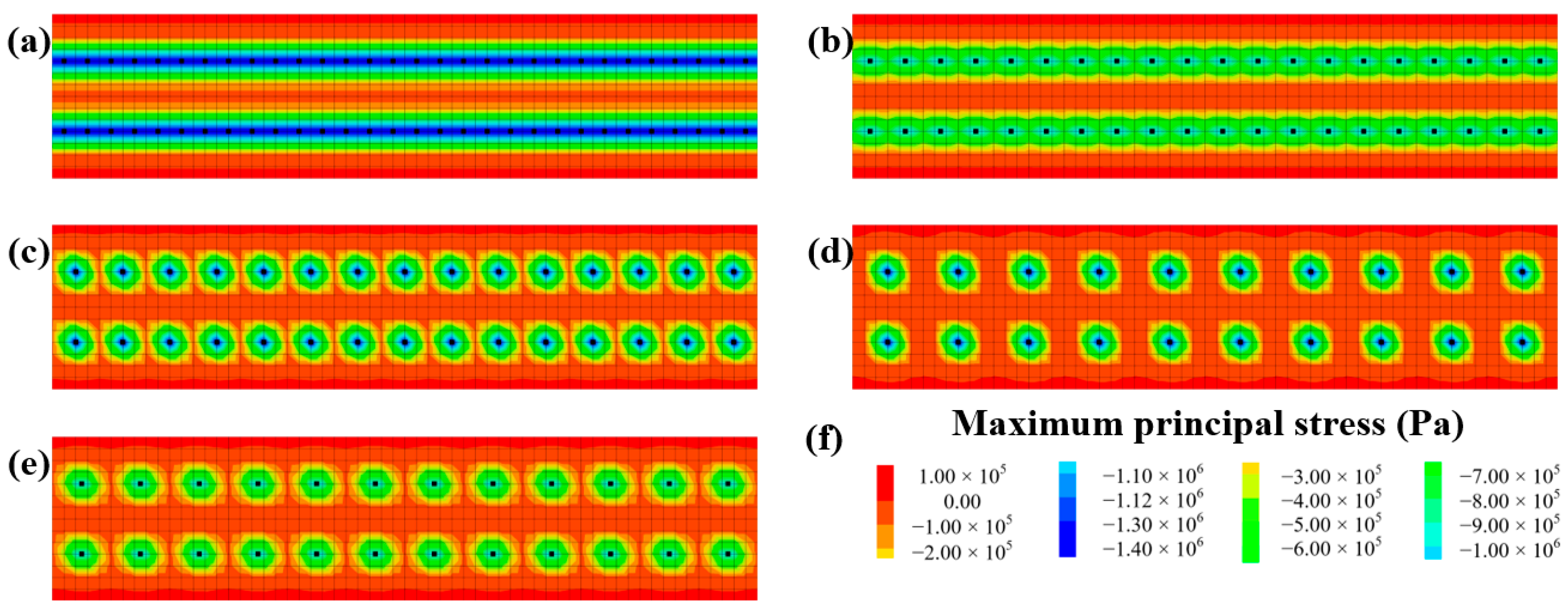
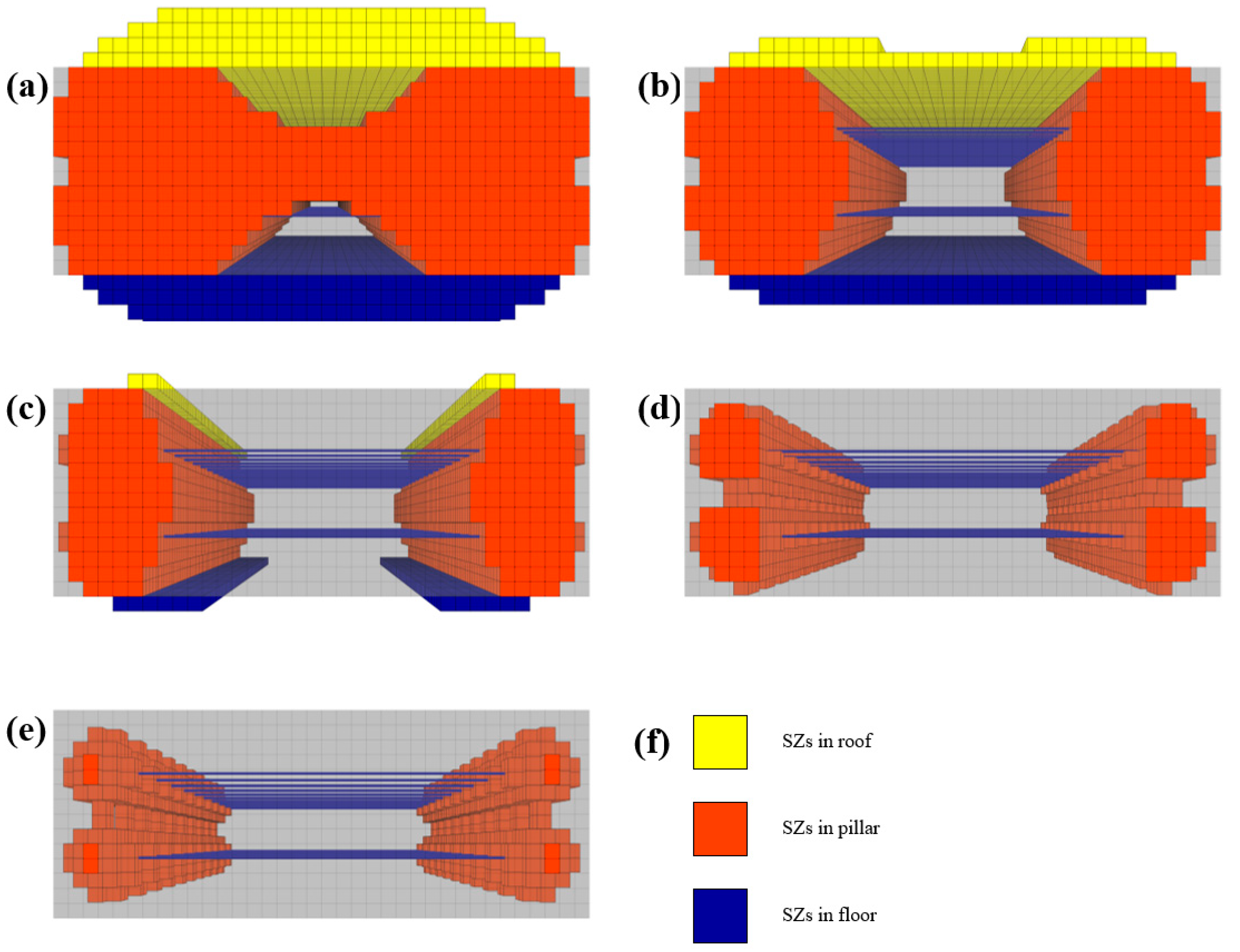
4.1. The Law of Support Stress Distribution with Different Two-End-Type Cable Schemes

As shown in Figure 7 and Figure 8, in all support cases, there were two cables in each row, leading to a stress distribution that was similar inside the pillar. Two stress concentration zones that were obviously compressive (SZs, support stress zones) were constructed, affected by pretension at the cable’s two ends. Meanwhile, the compressive stress produced in the cable’s free area gradually decreased as the distance from the end increased. Yet, stress distribution varied obviously for different cable row spacings, which may be conducive to the differences in bearing capacity. With a large row spacing, distribution of the support stress zones resulting from each cable was in isolation, and the prestressing impact imposed on the surrounding rock between neighboring cables was very restricted; with a small row spacing, the SZs resulting from the neighboring cables were superimposed. The prestressing had a greater support influence on the rock between the neighboring cables.

4.2. The Two-End-Type Cable’s Support Mechanism

Furthermore, to explore the distribution of stress owing to different cable support designs, zones with principal stress above 10 kPa were confirmed and marked as SZs with the FISH code according to Figure 7 and Figure 8. Table 4 and Figure 9 show the results. It is clear that the SZ distribution varied obviously with different cable row spaces. As the row spacing decreased, the SZs extended to a longer distance on both sides of the pillars. Figure 9e presents that with a 1.50 m row spacing, the SZs were relatively in isolation and the support stress stretched 1.25 m to the pillar on both sides. The SZs only occupied 11.56% of the entire pillar zones. As soon as the row spacing decreased to 1.25 m and 1.00 m, the support stress owing to adjacent cables was superimposed, and the support stress extended 1.5 m and 2.25 m to the pillar. The SZs rose to 24.90% and 44.39%, respectively. As the row spacing decreased to some extent, such as 0.75 m and 0.50 m, the SZs on the both sides of the pillar were linked together, and the entire coal body on the pillar’s surface was in the support stress zone. The support stress rises the radial stresses effectively and ameliorates the stress state in the pillar.
Additionally, as the row spacing decreased to 1.00 m, SZs extended to both the roof and floor. As the row spacing decreased to 0.75 m and 0.50 m, the SZ extension distances in the floor and roof were 1.00 m and 0.50 m, respectively. These results indicate that although the strengthening supports were horizontally installed by cable, the reinforcement still improved the stress state in the roof and floor.

5. Case Study

5.1. Coal Pillar Stability Control Strategy Using a Two-End-Type Cable

Previous research has shown that enlarging the support stress distribution can improve the roadway surrounding rock’s bearing capacity effectively [32,33], which is verified by the results in Section 3 and Section 4. The stress state of coal pillars varied with w/h ratio and cable row spacing, resulting in varying bearing capacity. Hence, different support strategies are needed on a case-by-case basis in accordance with available support types and expected pillar dimensions. Some advice for yield pillar support is summarized below:
(1)
As the row spacing of cables decreases, the proportion of the support stress zone in the coal pillar increases, and the pillar bearing capacity is significantly enhanced. However, for economic reasons, the row spacing of cables cannot be simply reduced since the reduction of the row spacing will increase the consumption of cables.
(2)
If an obvious rising in peak strength is taken as target, simply increasing the strength of the cable support is not sufficient. In all cases, the pillar peak strength increase is less than 5%.
(3)
As the width of the pillar falls, the ratio of residual/peak strength decreases, indicating the failure of the narrower pillars can be more violent. When the support density of the cable increases, the residual/peak strength ratio increases, which effectively improves the failure features of the pillar and avoids the violent failure of the pillar.
(4)
To study the two-end-type cable reinforcement, the bolt support reinforcement on the pillar was neglected in this research. However, in an actual production process, the reinforcement of bolt support on the yielding pillar cannot be ignored. Figure 10 reveals that although the coal pillar strength was increased slightly by bolt support alone, the effect of a combined bolt and cable support improved its strength greatly, often by more than the sum of the two. Therefore, the combined support effect of bolts and cables should be involved in designing coal pillar reinforcement support schemes.
The technology for failure heave and deformation controlling of narrow coal pillars has been discussed. However, most previous studies have improved the pillar stress state by optimizing the pillar design or by roof pre-splitting, etc. [34,35]. Few studies have focused on support design of narrow coal pillars. By analyzing and modelling coal pillar bearing capacity under the strengthening influence of a cable, this research offers some inspirations and references for surrounding rock control under similar geotechnical and geological situations.

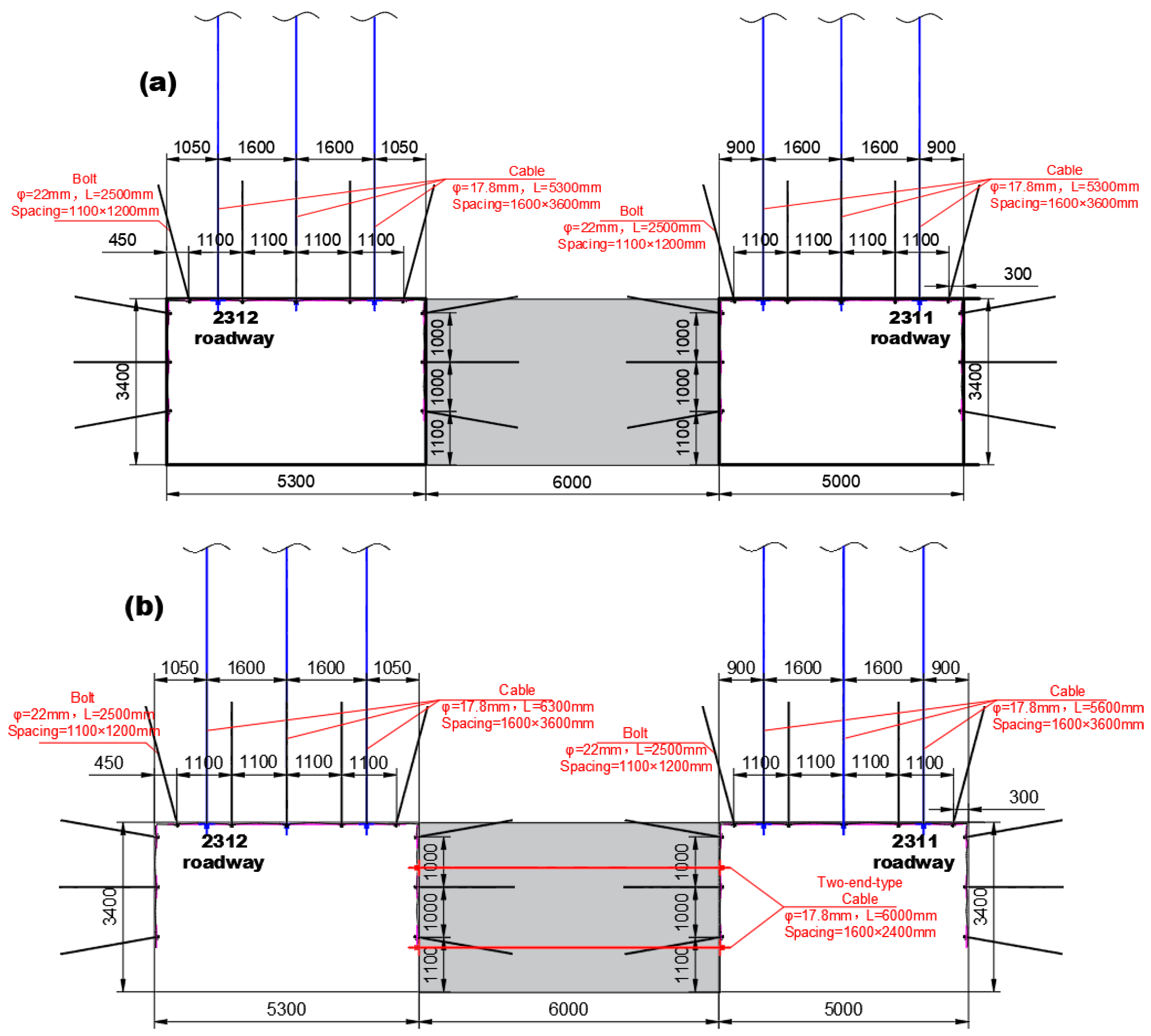
5.2. Technical Measures of Reinforced Support

Based on the aforementioned coal pillar stability control strategy and in conjunction with the numerical simulation results in Section 3, an optimized support approach was implemented during the on-site construction process. Building upon the existing support measures in the roadway, strengthened support was applied to the 6.0 m coal pillar segment using an enhanced support scheme that involved the utilization of two-end-type cables.
The support scheme before optimization is illustrated in Figure 11a. High-strength anchor rods with diameters of 22 mm and lengths of 2500 mm were employed for the roadway roof and rib support, respectively. Additionally, a 1 × 7 type cable with a diameter of 17.6 mm and a length of 6300 mm was used to support the roof, with spacing intervals of 1600 × 3000 mm. The pre-tension forces for the anchor rods and cables were 80 kN and 250 kN, respectively.
The support scheme after optimization is shown in Figure 11b. Through the implementation of two-end-type cables with a diameter of 21.8 mm and a length of 6600 mm, spaced at intervals of 1.6 m by 2.4 m, enhanced support was provided. The pre-tension force applied during cable installation was 250 kN.

5.3. Application Effect

To ascertain the viability of the newly proposed coal pillar stability control methodology, we adopted a cross-measurement technique, visualized in Figure 12. This technique aimed to meticulously record the deformation patterns of the surrounding rock in relation to the coal pillars located within the 2311 and 2312 roadways during the extraction processes at the 8311 working face. At the central zones of the roofs in both 2311 and 2312 roadways, specific pins were anchored onto the ribs of the yielding coal pillars. Within this context, the terms “A1O” and “A2O” specifically denote the convergence metrics of the ribs in the 2311 and 2312 roadways, respectively. A comprehensive representation of these measurements is provided in Figure 12.
At the 8311 working face, coal pillars in the 2312 roadway, positioned about 40 m from the forefront of the working face, began experiencing deformation due to the advancing supporting stress. As the face advanced closer to the measuring station, the rib convergence of coal pillars in the 2311 roadway was documented at 72 mm, compared to 65 mm for the 2312 roadway. Consequently, the cumulative expansion deformation for the coal pillar was 137 mm, translating to a deformation rate of roughly 2.28%. These data suggest that during the coal extraction at the 8311 face, the stability of the yielding coal pillars was adeptly preserved. Importantly, measurements were halted post the station’s ingress into the gob for safety considerations.

6. Conclusions

In this study, FLAC3D was utilized to create 30 distinct numerical models to examine the effect of cable reinforcement on yield pillars. These models varied in their width-to-height (w/h) ratios and cable support techniques. By observing support stress distribution in the adjacent rock, the mechanism behind cable support was further scrutinized.
(1)
The w/h ratio of coal pillars and the supporting power of bi-terminal cables played a significant role in enhancing the load-bearing ability of yield coal pillars. With augmented support strength, there was a notable rise in both peak and residual strengths across the coal pillar models. Interestingly, as the w/h ratios grew, there was a pronounced increase in peak strength, whereas the rise in residual strength was less evident.
(2)
Due to the effect of pretensioning, two pronounced zones of support stress were apparent at either end of the cable. In the intervening space, the stress diminished proportionately the farther it was from either end. However, different row spacings exhibited varied stress distributions, which could influence the bearing capacity. Smaller spacings resulted in more extensive support stress, which in turn positively affected the radial stresses and improved the pillar’s stress conditions.
(3)
Observations from field monitoring revealed that when mining advanced in the 8311 working face towards the measuring point, the convergence measurements in the ribs of the coal pillars for the 2311 and 2312 roadways were 72 mm and 65 mm, respectively. This suggests an overall expansion deformation of 137 mm, translating to a deformation magnitude of around 2.28%. Such findings confirm the yield coal pillar’s stability during the mining operations of the 8311 panel.
It is essential to mention that the simulations and subsequent evaluations in this research are rooted in the particular engineering geology of the Tashan coal mine. For a holistic understanding of bi-terminal cable reinforcement, future studies should delve into various aspects such as coal body resilience, plate structures at the top and bottom, the kind of anchor cable, and preload during installation, among others. Our next phase of research will delve deeper into these aspects, aiming to provide nuanced recommendations for designing underground pillar systems. To this end, laboratory experiments paired with on-site evaluations will be undertaken.

Author Contributions

Conceptualization, C.S. and S.C.; methodology, C.S.; software, C.S. and Z.Z.; validation, S.C.; formal analysis, S.C.; investigation, K.L.; resources, S.C.; data curation, J.S.; writing—original draft preparation, C.S.; writing—review and editing, S.C.; visualization, S.C.; supervision, S.C.; project administration, C.S.; funding acquisition, C.S. All authors have read and agreed to the published version of the manuscript.

Funding

The research was financially supported by the National Natural Science Foundation of China (grant number 52274143).

Data Availability Statement

Data will be made available on request.

Conflicts of Interest

The authors declare no conflict of interest.

References

  1. Chang, Q.; Ge, S.; Shi, X.; Sun, Y.; Wang, H.; Li, M.; Wang, Y.; Wu, F. Determination of Narrow Coal Pillar Width and Roadway Surrounding Rock Support Technology in Gob Driving Roadway. Sustainability 2022, 14, 4848. [Google Scholar] [CrossRef]
  2. Liu, H.-Q.; Wang, L.; Han, L.-C.; Liu, P.; Zou, P.; Liu, X. Study on the Instability Mechanism and Control Measures of a Roadway in a Mine with Retained Coal Pillars and Close Coal Seams. Shock Vib. 2021, 2021, 8871807. [Google Scholar] [CrossRef]
  3. Li, Z.; Yang, K.; Ji, J.; Jiao, B.; Tian, X.; Zhang, J. Analysis on Rock Burst Risks and Prevention of a 54 m-Wide Coal Pillar for Roadway Protection in a Fully Mechanized Top-Coal Caving Face. Shock Vib. 2021, 2021, 5584411. [Google Scholar] [CrossRef]
  4. Wang, Q.; Feng, H.; Tang, P.; Peng, Y.; Li, C.; Jiang, L.; Mitri, H.S. Influence of Yield Pillar Width on Coal Mine Roadway Stability in Western China: A Case Study. Processes 2022, 10, 251. [Google Scholar] [CrossRef]
  5. Wang, W.; Wu, Y.; Lu, X.; Zhang, G. Study on small coal pillar in gob-side entry driving and control technology of the sur-rounding rock in a high-stress roadway. Front. Earth Sci. 2023, 10, 221–226. [Google Scholar] [CrossRef]
  6. Zhang, S.; Wang, X.; Fan, G.W.; Zhang, D.; Jianbin, C. Pillar size optimization design of isolated island panel gob-side entry driving in deep inclined coal seam—Case study of Pingmei No. 6 coal seam. J. Geophys. Eng. 2018, 15, 816–828. [Google Scholar] [CrossRef]
  7. Su, M.; Gao, X. Research of the Surrounding Rock Deformation Control Technology in Roadway under Multiple Excavations and Mining. Shock Vib. 2021, 2021, 6681184. [Google Scholar] [CrossRef]
  8. Wang, D.; He, F.; Wu, Y.; Xu, X.; Zhang, J.; Lv, K.; Li, L.; Zhai, W.; Song, J. Study on surrounding rock failure mechanism and rational coal pillar width of the gob-side coal roadway under influence of intense dynamic pressure. Energy Sci. Eng. 2023, 11, 1716–1733. [Google Scholar] [CrossRef]
  9. Xie, S.; Guo, F.; Wu, Y. Control Techniques for Gob-Side Entry Driving in an Extra-Thick Coal Seam with the Influence of Upper Residual Coal Pillar: A Case Study. Energies 2022, 15, 3620. [Google Scholar] [CrossRef]
  10. Li, X.; Zhao, Y.; He, W.; Li, L.; He, F. Study on Coal Pillar Width and Surrounding Rock Control of Gob-Side Entry in Extra-thick Coal Seam. Geotech. Geol. Eng. 2020, 38, 6855–6868. [Google Scholar] [CrossRef]
  11. Gong, S.; Tan, Y.; Liu, Y.; Zhu, D.; Yu, Y.; Song, Z. Application of Presplitting Blasting Technology in Surrounding Rock Control of Gob-Side Entry Retaining with Hard Roof: A Case Study. Adv. Mater. Sci. Eng. 2021, 2021, 1318975. [Google Scholar] [CrossRef]
  12. Zhang, G.C.; Wen, Z.J.; Liang, S.J.; Tan, Y.L.; Tian, L.; Zhao, Y.Q.; Zhao, D.S. Ground Response of a Gob-side Entry in a Longwall Panel Extracting 17 m-Thick Coal Seam: A Case Study. Rock Mech. Rock Eng. 2019, 53, 497–516. [Google Scholar] [CrossRef]
  13. Wu, R.; He, Q.; Oh, J.; Li, Z.; Zhang, C. A New Gob-Side Entry Layout Method for Two-Entry Longwall Systems. Energies 2018, 11, 2084. [Google Scholar] [CrossRef]
  14. Wang, M.; Xu, Y.; Xu, Q.; Shan, C.; Li, Z.; Nan, H.; Li, Y.; Liu, H.; Chu, T. Stability control of overburden and coal pillars in the gob-side entry under dynamic pressure. Int. J. Rock Mech. Min. Sci. 2023, 170, 105490. [Google Scholar] [CrossRef]
  15. Liu, Q.; Ling, H.; Lu, Y.; Lin, J.; Liu, Y.; Wang, J.; Huang, W.; Wang, L.; Yin, Z. Residual Strength Estimation Method of Soft Coal Based on Equivalent Residual Strain Ratio. Geofluids 2022, 2022, 8079568. [Google Scholar] [CrossRef]
  16. Liu, X.; Shen, W.; Bai, J.; Wang, R.; Kang, J.; Wang, X.; Zhu, Z. Mining-Induced Redistribution of the Abnormal Stress under the Close Bearing Coal Pillar for Entry Design. Adv. Civ. Eng. 2021, 2021, 5595372. [Google Scholar] [CrossRef]
  17. Han, P.; Zhang, C.; Wang, W. Failure analysis of coal pillars and gateroads in longwall faces under the mining-water invasion coupling effect. Eng. Fail. Anal. 2021, 131, 105912. [Google Scholar] [CrossRef]
  18. Ren, J.; Zhao, Y.; Wang, W.; Guo, J.; Sun, Z.; Liu, S. Optimal Design of a Protective Coal Pillar with a Buried Pipeline in a Thick Loose Layer in Western China: Methodology and Case Study. Rock Mech. Rock Eng. 2023, 56, 2879–2896. [Google Scholar] [CrossRef]
  19. Yue, X.; Tu, M.; Li, Y.; Chang, G.; Li, C. Stability and Cementation of the Surrounding Rock in Roof-Cutting and Pressure-Relief Entry under Mining Influence. Energies 2022, 15, 951. [Google Scholar] [CrossRef]
  20. Yang, S.; Ning, J.; Gao, M.; Wang, J.; Shi, X.; Hu, S.; Li, Y. Instability mechanism and stability control of gob-side entry in a deep mine: A case study. Bull. Eng. Geol. Environ. 2023, 82, 346. [Google Scholar] [CrossRef]
  21. Hou, C.; Zhu, W.-C.; Yan, B.-X.; Yang, L.-J.; Du, J.-F.; Niu, L.-L. Mechanical behavior of backfilled pillar under biaxial loading. J. Central South Univ. 2023, 30, 1191–1204. [Google Scholar] [CrossRef]
  22. Qu, X.; Chen, Y.; Yin, D. Experimental study on progressive failure characteristics of strip coal pillar models under different roof and floor conditions. Case Stud. Constr. Mater. 2023, 18, e02147. [Google Scholar] [CrossRef]
  23. Sahoo, S.K.; Singh, G.S.P.; Sharma, S.K.; Singh, U.K. Numerical Modeling Study of the Influence of Softcover on Strata and Support Behavior in a Bord and Pillar Depillaring Working. Min. Metall. Explor. 2020, 37, 1151–1168. [Google Scholar] [CrossRef]
  24. Abousleiman, R.; Walton, G.; Sinha, S. Understanding roof deformation mechanics and parametric sensitivities of coal mine entries using the discrete element method. Int. J. Min. Sci. Technol. 2020, 30, 123–129. [Google Scholar] [CrossRef]
  25. Li, L.; Li, G.; Gong, W.; Wang, J.; Deng, H. Energy Evolution Pattern and Roof Control Strategy in Non-Pillar Mining Method of Goaf-Side Entry Retaining by Roof Cutting—A Case Study. Sustainability 2019, 11, 7029. [Google Scholar] [CrossRef]
  26. Mo, S.; Canbulat, I.; Zhang, C.; Oh, J.; Shen, B.; Hagan, P. Numerical investigation into the effect of backfilling on coal pillar strength in highwall mining. Int. J. Min. Sci. Technol. 2017, 28, 281–286. [Google Scholar] [CrossRef]
  27. Das, A.J.; Mandal, P.K.; Paul, P.S.; Sinha, R.K.; Tewari, S. Assessment of the Strength of Inclined Coal Pillars through Nu-merical Modelling based on the Ubiquitous Joint Model. Rock Mech. Rock Eng. 2019, 52, 3691–3717. [Google Scholar]
  28. Zhang, G.-C.; Tan, Y.-L.; Liang, S.-J.; Jia, H.-G. Numerical Estimation of Suitable Gob-Side Filling Wall Width in a Highly Gassy Longwall Mining Panel. Int. J. Géoméch. 2018, 18, 04018091.1–04018091.15. [Google Scholar] [CrossRef]
  29. Wang, C.; Lu, Y.; Shen, B.; Li, Y.; Liang, Y. Design and monitoring of CPB replacement mining RSCP: A case study in China. Energy Sources Part A Recover. Util. Environ. Eff. 2019, 43, 80–95. [Google Scholar] [CrossRef]
  30. Jiang, Y.; Zhao, Y.; Wang, H.; Zhu, J. A review of mechanism and prevention technologies of coal bumps in China. J. Rock Mech. Geotech. Eng. 2017, 9, 180–194. [Google Scholar] [CrossRef]
  31. Lv, J.; Wan, Z.; Zhang, Y.; Wang, J.; Yan, W.; Xiong, L. Effect of multi-factor dynamic loading on gob-side entry driving during longwall face extraction: A case study. Bull. Eng. Geol. Environ. 2022, 81, 409. [Google Scholar] [CrossRef]
  32. Zhao, P.; Zhang, W.; Li, S.; Chang, Z.; Lu, Y.; Cao, C.; Shi, Y.; Jia, Y.; Lou, F.; Wei, Z.; et al. Numerical Simulation Study on Mechanical Characteristics and Width Optimization of Narrow Coal Pillar in Gob-Side Coal Seam Tunnel. Sustainability 2022, 14, 16014. [Google Scholar] [CrossRef]
  33. Yang, R.; Zhu, Y.; Li, Y.; Li, W.; Lin, H. Coal pillar size design and surrounding rock control techniques in deep longwall entry. Arab. J. Geosci. 2020, 13, 453. [Google Scholar] [CrossRef]
  34. Xu, J.; Li, G.; Gomah, M.E.; Chen, B.; Sun, C.; Rong, H.; Zhang, Q. Overlying main roof breaking characteristic and its effect on the stability of gob-side entry. Géoméch. Geophys. Geo-Energy Geo-Resources 2023, 9, 1–15. [Google Scholar] [CrossRef]
  35. Yang, Y.; Zhang, Y.; Shen, W. Research on the Technology of Small Coal Pillars of Gob-Side Entry Retained in Deep Mines Based on the Roof Cutting for Pressure Unloading in the Lower Key Stratum. Geofluids 2022, 2022, 7701154. [Google Scholar] [CrossRef]
Figure 1. Stratum synthesis histogram.
Energies 16 06418 g001
Figure 2. A coal pillar sub-model and the boundary conditions.
Energies 16 06418 g002
Figure 3. Calibration result of the pillar model.
Energies 16 06418 g003
Figure 4. Peak strength increase in coal pillars with different support strengths of two-ended cables and different pillar widths: (a) peak strength increase versus support strength of two-ended cables; (b) peak strength increase versus pillar width.
Energies 16 06418 g004
Figure 5. Residual strength increase versus support strength of two-ended cables: (a) residual strength increase versus support strength of two-ended cables; (b) residual strength increase versus pillar width.
Energies 16 06418 g005
Figure 6. Three-dimensional plot revealing the difference between peak strength increase and residual strength increase.
Energies 16 06418 g006
Figure 7. Support stress distributions for various support designs: (a) support design with 500 mm row spacing; (b) support design with 750 mm row spacing; (c) support design with 1000 mm row spacing; (d) support design with 1250 mm row spacing; (e) support design with 1500 mm row spacing; (f) color scale.
Energies 16 06418 g007
Figure 8. Support stress distributions for various support designs: (a) support design with 500 mm row spacing; (b) support design with 750 mm row spacing; (c) support design with 1000 mm row spacing; (d) support design with 1250 mm row spacing; (e) support design with 1500 mm row spacing; (f) color scale.
Energies 16 06418 g008
Figure 9. Distributions of support stress for various support designs: (a) support design with 500 mm row spacing; (b) support design with 750 mm row spacing; (c) support design with 1000 mm row spacing; (d) support design with 1250 mm row spacing; (e) support design with 1500 mm row spacing; (f) legend.
Energies 16 06418 g009
Figure 10. Support stress distributions for different support designs: (a) strength; (b) strength increase.
Energies 16 06418 g010
Figure 11. Support scheme: (a) before and (b) after strengthening.
Energies 16 06418 g011
Figure 12. Convergences of pillar ribs during the 8311 panel retreat.
Energies 16 06418 g012
Table 1. Mechanical and physical parameters of rock mass and interface.
LithologyThickness
(m)
Density (kg·m−3)Bulk Modulus (GPa)Shear Modulus (GPa)Cohesion (MPa)Friction Angle
(°)
Tensile Strength (MPa)
Roof10.0250014.0011.514.5434.7
4 coal3.415000.910.423.29300.7
Floor10.0250014.008.403.8404.7
InterfaceNormal stiffness = 100 GPa/m; shear stiffness = 50 GPa/m;
Interface cohesion = 0.795 MPa; internal friction angle = 31°
Table 2. Variation of coal mechanical properties with plastic shear strain.
Plastic Strain00.0050.051
Cohesion (MPa)3.291.970.660.66
Friction angle (°)30221818
Table 3. Pillar strengths with different support designs of two-ended cables.
Pillar StrengthRow Spacing (m)Support Strength (MPa)Pillar Height (m)
5.0 (w/h = 1.43)6.0 (w/h = 1.71)7.0 (w/h = 2.0)8.0 (w/h = 2.28)9.0 (w/h = 2.57)
Peak strength
(MPa)
N/A06.097.168.139.1310.29
1.500.206.147.268.219.2310.41
1.250.246.157.288.239.2510.44
1.000.306.187.318.269.2910.49
0.750.406.217.348.319.3710.57
0.50.606.267.418.419.5010.74
Residual strength
(MPa)
N/A01.381.792.272.763.26
1.500.201.471.892.382.883.40
1.250.241.481.912.402.903.42
1.000.301.521.952.442.953.47
0.750.401.551.992.492.993.52
0.50.601.632.072.583.113.64
Residual/peak strength ratio (%)N/A022.6625.0027.9230.2331.68
1.500.2023.9426.0328.9931.2032.66
1.250.2424.0726.2429.1631.3532.76
1.000.3024.6026.6829.5431.7533.08
0.750.4024.9627.1129.9631.9133.30
0.50.6026.0427.9430.6832.7433.89
Note: N/A indicates not applicable.
Table 4. Pretensioned zone distribution with different support designs.
Row Spacing (m)SZs in the PillarsPercentage of SZs in the Pillar Zones (%)
0.5021,60091.84
0.7517,48074.32
1.0010,44044.39
1.25585624.90
1.50272011.56
Note: SZs: support stress zones.
Disclaimer/Publisher’s Note: The statements, opinions and data contained in all publications are solely those of the individual author(s) and contributor(s) and not of MDPI and/or the editor(s). MDPI and/or the editor(s) disclaim responsibility for any injury to people or property resulting from any ideas, methods, instructions or products referred to in the content.

