Review

Methane Pyrolysis with the Use of Plasma: Review of Plasma Reactors and Process Products

by
Mateusz Wnukowski
Faculty of Mechanical and Power Engineering, Wroclaw University of Science and Technology, 27 Wybrzeze St. Wyspianskiego, 50-370 Wroclaw, Poland
Energies 2023, 16(18), 6441; https://doi.org/10.3390/en16186441
Submission received: 8 July 2023 / Revised: 13 August 2023 / Accepted: 22 August 2023 / Published: 6 September 2023
(This article belongs to the Special Issue Plasma Application in Fuel Conversion Processes)

Abstract

:
With the increasing role of hydrogen in the global market, new ways of hydrogen production are being sought and investigated. One of the possible solutions might be the plasma pyrolysis of methane. This approach provides not only the desired hydrogen, but also valuable carbon-containing products, e.g., carbon black of C2 compounds. This review gathers information from the last 20 years on different reactors that were investigated in the context of methane pyrolysis, emphasizing the different products that can be obtained through this process.

1. Introduction

The constantly increasing global concern regarding climate change caused by anthropogenic CO2 emission has resulted in great attention given to hydrogen as one of the possible solutions [1]. Hydrogen utilization is discussed and slowly implemented in almost every crucial area, e.g., automotive industry [2,3], railway transport [4], household applications [5,6], energy production and storage [7], and heavy industry [8]. In these scenarios, the most-common assumption is that the hydrogen origin is green, meaning it is produced with the use of electrolysis. However, more and more attention is being given to turquoise hydrogen. This color is assigned to hydrogen derived from methane pyrolysis, which can be described as in Equation (1):
C H 4 2 H 2 + C
The enthalpy of this reaction, calculated based on H2 mol (37.4 k J m o l H 2 ), is several times smaller than that of water electrolysis (285.8 k J m o l H 2 ). Moreover, the cost of turquoise hydrogen can be lower than that of green hydrogen [9]. Therefore, with a developed natural gas network and its easy storage and transportation, methane pyrolysis is often considered a short-to-medium-term approach that could be used until water electrolysis becomes more available and widespread [9,10]. Opposite steam methane reforming (SMR), pyrolysis produces no CO2. If carbon capture and storage (CCS) is taken into account, the price of turquoise hydrogen can be on the same level as blue hydrogen (SMR + CCS) [9], yet without the technical problems and risks arising from CCS on a large scale [11]. While the aim of using fossil fuels like natural gas can be questioned due to their depleting resources and in light of recent geopolitical developments, it should be noted that natural gas is not the only source of methane. Other possible sources are flared gas, refinery gas, landfill gas, and biogas. The last two are especially crucial, as they will be produced even in the scenario of a complete abandoning of fossil fuels, and their utilization can provide negative CO2 emissions. Taking into account the potential of biogas that has not yet been explored in many regions [12,13], coupling these two into biomethane pyrolysis appears to be very promising.
Methane pyrolysis processes can be grouped into three main categories: thermal, catalytic, and plasma. Perhaps surprisingly, the plasma methods are the most-mature technology. As pointed out in [9], plasma methane pyrolysis is a technology that was already industrially applied, granting a technology readiness level (TRL) of 8. In comparison, thermal and catalytic methods are presently at a TRL of 4 at best. An up-to-date presentation of some companies’ efforts toward methane pyrolysis is given in [9,14]. The main benefit of plasma technologies is a direct energy transfer to the processed gas and an instant ON/OFF procedure. In other words, while thermal and catalytic methods will require a slow and controlled heating up and cooling off, with their reactors operating for as long as possible, plasma reactors can be turned off at any time with no repercussions. This seems to match perfectly with time-dependent renewable energy sources based on solar or wind energy. Nevertheless, a comprehensive review of many methane pyrolysis methods can be found in [15,16,17,18,19].
When considering methane pyrolysis, the most-common approach is to focus on H2 and carbon black production (as in Equation (1)). This seems reasonable in the context of H2 production, as the process conducted in this manner will provide the highest yield of hydrogen. Moreover, the process is relatively easy to predict and control, as it simply requires severe enough conditions (temperature and time). However, this is not always the case. Methane pyrolysis gives the potential of many other valuable products. In fact, aiming for combined hydrogen/carbon black might be short-sighted as the market for the latter has a limited capacity [10,14]. For instance, as pointed out by N. Sánchez-Bastardo et al. in [10], in 2017, the global annual demand for hydrogen was ca. 60 million t. This amount would result in the production of 180 million t of carbon black. Meanwhile, the current carbon product demand is estimated at a level of ca. 15–20 million. It should be noted that the hydrogen demand will soon increase sharply from the 2017 levels, making the potential carbon black demand–supply even more unbalanced. Therefore, it seems reasonable to look for other possible by-products. One of the potentially high-value products would be C2 olefins, with their demand reaching hundreds of millions of tons annually and expected to increase [20,21]. It should be highlighted that, normally, these products are obtained from crude oil with CO2 as a byproduct [21]. Therefore, applying much more available substrates, such as methane/biomethane, in a CO2-neutral process seems a much-more-sustainable approach. In fact, coupling methane into C2 molecules is often considered a “Holy Grail” for chemists [22]. The process of methane coupling can be oxidative or non-oxidative. In the first case, the main problem is the low selectivity of C2 products and the high carbon oxides [22]. Therefore, non-oxidative methods are in higher demand. As this process is basically pyrolysis in its principles, it can be grouped again into thermal, catalytic, and plasma methods. As the thermal methods suffer from a wide range of products and the catalytic methods from a catalyst deactivation, many researchers focus on plasma applications [22,23], especially since this kind of technology was already tested on an industrial scale in the Huels process [24].
Although there have already been a few review articles that consider the plasma pyrolysis of methane, these works often emphasize different parts of the topic. For example, works [9,25] focus mainly on hydrogen production. Work [26] discusses plasma-assisted methane reforming in general, e.g., including steam and dry reforming. The most-comprehensive study considering specifically methane plasma pyrolysis appears to be the work of M. Scapinello et al. [23]. However, it focuses mainly on process efficiency and acetylene formation and only briefly presents thermal plasma reactors. Therefore, the objective of this review is to present an up-to-date wide range of plasma reactors used for plasma pyrolysis. The main point that distinguishes it from the other reviews is the focus given to the very different products that can be obtained in different reactors.

2. Basics of Methane Pyrolysis

Methane pyrolysis is an endothermic process requiring high temperatures due to the strong C-H bond (434 kJ/mol) [27]. Very often, it is represented as in Equation (1) with its enthalpy being 74.9 kJ/mol. This one-step reaction is justified if the process is conducted in severe enough conditions (time and temperature). Normally, the formation of intermediate products (e.g., unsaturated hydrocarbons) is faster than a complete dehydrogenation of methane [28]. Therefore, in the temperature range of 1000–3000 K, a wider range of products is possible (including C2H6, C2H4, C2H2, and benzene), and the reaction can be described as follows:
2 C H 4 C 2 H 6 + H 2 C 2 H 4 + 2 H 2 C 2 H 2 + 3 H 2 2 C + 4 H 2
It should be noted that the selectivity of the products shifts more to the right with an increase in the reaction temperature and time [29]. In practice, all products can coexist, but, due to the high temperature required for methane pyrolysis, the main carbon products are usually soot, C2H2, and C2H4 to a lesser extent [15,28,30]. The presence of aromatics is also possible [31], as they are intermediate products in the HACA mechanism, leading to the formation of soot [32,33]. However, their concentration is negligible if no catalyst is applied [30,31]. C2H6 is another product that can be present in the products’ stream, yet its high selectivity is typical for non-thermal plasmas [23]. Regardless of the products, the initial step in methane pyrolysis is the formation of methyl radicals (Equation (3)):
C H 4 + M C H 3 + H + M
with M being a neutral molecule with energy high enough to detach hydrogen (e.g., another methane molecule).
The presence of H radicals is crucial for the propagation of methane pyrolysis reactions (Equation (4)), as it is the dominating path leading to methyl radical formation [34,35].
C H 4 + H C H 3 + H 2
The CH3 radical is crucial for the methane pyrolysis mechanism. It can dimerize into C2H6, which is considered the initial product of methane pyrolysis [10], or undergo subsequent dehydrogenation into CHx radicals (i.e., CH2, CH) [36]. Subsequently, the C2 compounds can be produced via ethylene dehydrogenation and CHx radical coupling [37].
If plasma methods are applied for methane pyrolysis, new routes of this molecule dissociation are possible. The first one involves a direct impact of highly energetic electrons present in the plasma, as expressed in Equations (5)–(8) [22,23]:
C H 4 + e C H 3 + H + e
C H 4 + e C H 2 + H 2 + e
C H 4 + e C H + H 2 + H + e
C H 4 + e C + 2 H 2 + e
These types of reactions require high electron energy (from 9 eV to 14 eV) [23], which is typical for non-equilibrium plasmas. Conversely, low-energy-level electrons (ca. 1–2 eV), typical for microwave and gliding arc plasma, can result in methane molecule vibrational excitation [38]. The vibrational excitation increases the energy of methane molecules gradually, lowering the dissociation activation energy and making the process more efficient [38]. However, these vibrationally excited states are very short-lived [38,39] and may not play any crucial role in methane decomposition, as computational simulations showed [40]. Surely, in many cases, plasma provides a gas temperature high enough that thermally driven processes, like in classical pyrolysis, are accessible. A more-comprehensive description of the plasma-assisted methane decomposition mechanisms is given in [25,26]. Finally, it should be noted that the discussed process of methane conversion can be referred to as pyrolysis, decomposition, dissociation, coupling, or non-oxidative coupling. The last two are used specifically for the case when the formation of C2 molecules is the main goal. In this review, all these names will be used.

3. Types of Plasma Reactors Used for Methane Pyrolysis

In essence, plasma is an ionized gas, often referred to as a fourth state of matter. Plasma is widely used in many technical fields on an industrial scale, for example in lamps, in the production of electronic devices, in metallurgy, in chemical synthesis, or in waste disposal. The multitude of applications of plasma results from its unusual properties. Firstly, the temperature of the plasma exceeds values that are not achievable by other solutions. Secondly, plasma is characterized by a high concentration of highly energetic and chemically active particles (e.g., electrons, ions, radicals, excited particles). Third, plasma may be far from thermodynamic equilibrium, which means that some of its particles may have a different temperature than others. The temperature of the particles is indeed one of the basic parameters describing plasma. Energy transfer in plasma starts with electrons, e.g., by accelerating them in an electric field, which then transfers it to heavier particles (neutral particles). As a result, electrons and heavier particles may have different kinetic energies (temperatures). Under appropriate conditions, i.e., with high energy supplied to the plasma, after a sufficiently long time and with small heat losses, the energy between the particles equalizes, and the temperature of the electrons (Te) becomes equal to the temperature of the heavier particles (T0), which is identified as the gas or translational temperature (Tg). When this happens, the plasma is in local thermodynamic equilibrium (LTE), and the plasma itself is called thermal or equilibrium plasma [41]. Thermal plasma is characterized by a temperature of 103–104 K and is usually used as a source of high-temperature heat [42]. At such a high temperature, all chemical compounds are usually decomposed by thermal dissociation [42]. In a situation where both temperatures (Te and T0) differ significantly, the plasma is called non-equilibrium, non-thermal, or cold plasma. The rule is, due to the direction of energy transfer, in non-equilibrium plasma, Te >> T0. Moreover, for many non-thermal plasmas, the following relation between temperatures is true: Te > Tv > Tr ≈ Ti ≈ T0. The electron temperature is followed by the vibrational temperature Tv (oscillatory energy of molecules) and then by the rotational temperature Tr (energy of rotation of molecules), which is close to the temperature of ions (Ti) and neutral particles (the same as the temperature of the gas) [41]. In non-equilibrium plasma, chemical conversion is initiated by a high temperature of free electrons, i.e., greater than or equal to 104 K, at a relatively low gas temperature of 103 K [42]. The nature of the plasma, i.e., the presence or absence of LTE, depends on many factors, including the type of electrical discharge, its power density, its duration, the degree of ionization, and pressure [43,44]. Despite this simple division into equilibrium and non-equilibrium plasmas, the different types of discharges within the same category can differ significantly from each other. Therefore, the most-precise categorization of plasma is probably based on the type of discharge. With this assumption, among the most-widely used plasmas in methane pyrolysis, one can distinguish dielectric barrier (DBD), corona, spark, streamer, glow, microwave (MW) plasma, gliding arc, and arc discharges. All these types of plasma reactors will be described in more detail in the following sections. A brief summarization of the differences between the discharges is given in Figure 1 (based mainly on [44,45]).

4. Non-Thermal Plasma Methane Pyrolysis

4.1. DBD Plasma

4.1.1. Introduction

One of the most-commonly investigated types of plasma, in the context of methane coupling, is DBD plasma. In its basis, the DBD plasma reactor consists of two electrodes, which are usually parallel or cylindrical (with the coaxial geometry of a central rod acting as a power electrode), with the latter being most commonly used for gas processing. What is crucial is that the electrodes are separated with a dielectric (very often a quartz tube, but also alumina, ceramic, or plastic). The dielectric layer accumulates charged particles with an even distribution and prevents arc formation, thus limiting the current and temperature in the reactor [46,47]. Examples of the cylindrical geometry of a DBD reactor are shown in Figure 2 [48]. Usually, the plasma is sourced with AC voltage in the range of 1–30 kV with the frequency typically up to 20 kHz [47]. A higher frequency might be ineffectual or can even lower the process parameter, e.g., CH4 conversion and desired product selectivity, as proven experimentally by C. Xu and X. Tu [49]. The DBD plasma is an explicit representation of non-thermal plasma with a high non-equilibrium between Te and the gas temperature. While the former can be as high as 10 eV (enough to enable the reaction presented in Equation (5)), the latter is usually close to ambient temperatures. Depending on the applied voltage and experiment time, the gas temperature can sometimes reach 375 K [50,51,52,53]—a temperature that is too low to allow thermally driven methane decomposition. However, the gas temperature can be easily controlled (e.g., by an external heating source) [47,54,55]. Additionally, the reactor does not require a vacuum to sustain the plasma and can be filled with a catalyst or packing material [47,50,56]. All these traits make the DBD plasma a common choice in gas processing, including methane pyrolysis.

4.1.2. Standard Reactors

The experimental DBD reactors tested in the context of CH4 decomposition are usually small, cylindrical devices with flow rates varying from as low as 0.01 SLM [57] up to 1.5 SLM [58]. The input power is, therefore, low, varying by a few to dozens of Watts. The reactors usually work at ambient pressure. The conversion of methane rarely exceeds 50%, and the main hydrocarbon product is C2H6. This is caused by the electron-driven methane decomposition (Equation (5)) and the coupling of CH3 radicals into ethylene [54]. However, many other products are coproduced as well.
In the work of L. Liu et al. [59], the authors investigated methane coupling in a typical cylindrical DBD reactor. A steel rod was used as a high-voltage electrode and aluminum foil wrapped around a quartz tube as a ground electrode. A 30 kV voltage with a 10 kHz frequency was applied. The input power varied from 7 W to 72 W, while the gas flow rate was kept at 0.02 SLM. The gas was composed of pure CH4 or a mixture of CH4 and He in equal parts. In the given input power range, the methane conversion reached 7–37%. The corresponding C2 compounds’ selectivity was from 15–19%. The low C2 selectivity was explained by multiple coexisting side reactions, resulting in the formation of higher hydrocarbons and coke. In the same work, a case with the use of a catalyst (Pt/CeO2) gave more-detailed information on the distribution of the products. The C2 compounds’ share was in the range of 46–59%, followed by the C5+ compound (26–48%), and then C3 (5–9%) and C4 (1–6%), depending on the discharge power. In the C2 compounds’ group, C2H6 was dominant (79–92%), with C2H4 reaching a 5–11% share and C2H2, 3–10%. While these results were achieved with the use of a catalyst that increased the C2 compounds’ selectivity, the general product distribution is similar to other works in the field. For instance, in work [49], the selectivity of the hydrocarbons was as follows: C2H6 > C4H10 > C2 olefins > C3H8. However, depending on the discharge power and residence time, butane and C2 olefins could switch places. The authors did not mention any presence or problems connected to soot formation. The conversion rate of methane was dependent mostly on the input power, and for the range of 15 W to 55 W, it changed from ca. 10.5% to 21.8%. The tests were performed with pure CH4 (0.05–0.3 SLM). The DBD reactor was supplied by an AC high-voltage power supply with a peak voltage of 40 kV and a variable frequency of 20−50 kHz. More-detailed results from this work are shown in Figure 3. In the work of S. Zhang et al. [53], the main compound after C2H6 was C3H8, followed by C2H2, C4H8, and C2H4. It should be noted that the selectivity of these compounds summed up to 50%, and the rest was attributed to possible liquid hydrocarbons and solid particles, which were difficult to observe or measure. The achieved conversion was between 6.2% and 9.6% for a voltage ranging from 16 kV to 20 kV.
In the work of R. Snoeckx [48], a N2-CH4 DBD plasma was investigated in the context of nitrogen’s influence on CH4 conversion to H2. The results showed that, despite a significant share of nitrogen (from 1 ppm to 99%), no nitrogen-containing compounds (i.e., HCN and NH3) were detected. The presence of HCN was also assumed in the work of X. Mao et al. [60], yet it was not confirmed experimentally. In this work, however, the DBD reactor was working at a pressure of only 60 Torr, and the nitrogen-excited molecules were said to play a major role in methane pyrolysis. Regardless of the conditions, the main product was again C2H6, and a solid deposit was observed in the reactor. Another deviation from a typical cylindrical atmospheric-pressure reactor used in methane pyrolysis is a plane reactor. Despite this change in the reactor’s geometry, the results were not so different. The experiments of K. Thanyachotpaiboon et al. [61] showed that the major products were C2H6 (ca. 40% selectivity), C3H8 (15%), C4H10 (8%), and C2H4 (3%), which were accompanied by soot formation. Summarizing the distribution of the products in DBD reactors, a general trend was clearly presented in the work of N. Garcia-Mocanda et al. [62]: C (carbon deposit) > H2 > saturated hydrocarbons > unsaturated hydrocarbons. Out of the saturated hydrocarbons, the unambiguously dominating compound is C2H6, which can be followed by C3H8 or C4H10, depending on the conditions, and some other heavier compounds. In the case of unsaturated hydrocarbons, they usually include C2H4 and C2H2. However, some research reported the presence of small amounts of C3H6 [50] and even C4–C5 olefins [55,58]. While the soot/coke/deposit product is often the main one, very little information on it is given. It is assumed that its formation proceeds through acetylene, which is considered the main precursor of carbon formation [62]. J. Kim et al. [51] analyzed the deposit with the use of TG/DTA, XRD, and FT-IR. The result indicated that the deposit consists of two carbon species with an amorphous form dominating. In the work of Boutot et al. [58], the carbon deposit was accompanied by oily liquids. In fact, a greasy/polymeric character of the deposit was also reported in another paper [48]. The FT-IR analyses of the deposit in works [51,58] confirmed the presence of long-chain hydrocarbons. This suggests that the deposit might be a mixture of heavy chain hydrocarbons and carbon deposit. The SEM/TEM analyses of the deposit showed that the 20–30 nm carbon particles tend to agglomerate into 3–5 μm-diameter particles [58].
To improve the selectivity of the most-desirable products, usually considered C2 olefins, a few different approaches were introduced.

4.1.3. Two-Stage DBD Thermal Reactor

In the recent work of R. Liu et al. [54], it was shown that a higher selectivity of C2H4 was possible if a high temperature (over 800 °C) was applied. However, this was accompanied by a low conversion rate of CH4, creating a specific trade-off: high conversion rate or high C2H4 selectivity. A solution was found in the separation of the plasma stage from the high-temperature stage. As a result, the saturated hydrocarbons from the DBD plasma were pyrolyzed in a high-temperature stage, converted mainly into C2H4. The differences between the results from the DBD discharge process alone, thermal process alone, and combined processes are presented in Figure 4.

4.1.4. Catalyst-Assisted DBD

Another possible modification is to introduce packing/a catalyst into the DBD reactor. While catalytic CH4 pyrolysis is not the topic of this review, it is hard to omit it completely, as it is very common to match this type of plasma with packing material. The low temperature of the plasma prevents the sintering of the catalyst and can create unique phenomena via the interaction between the reactor’s filling and the plasma active species.
Even without any active metallic catalyst, the packing material itself can significantly influence methane coupling in a DBD reactor. This is assumed to be due to many factors, such as the enhanced local electric field, increased electron energy, and improved gas-plasma contact [51]. In the work of J. Kim et al. [51], the influence of the different sizes of three different packing materials (i.e., α-Al2O3, sea sand, and KIT-6) was investigated. The tests were performed with the use of a cylindrical DBD reactor working at atmospheric pressure. A gas mixture of CH4 and N2 (with equal shares) was applied with a volumetric flow rate of 0.04 SLM. The applied voltage and the frequency were 15 kV and 1 kHz, respectively. The discharge power was in the range of 36–44 W. The presence of packing material increased the methane conversion rate from ca. 20% for the blank test to 60%, depending on the packing material and its particle size. Considering the products, the presence of packing material significantly increased the selectivity of C2 olefins and H2 at the cost of C2H6 and, to a lesser extent, C3 and C4 hydrocarbons. Although a carbon deposit was produced on the surface of the packing material, it was not determined whether it affected the process in the long term. Similar results were obtained in the work of M. Taheralsani and H. Gardeniers [50], who investigated the influence of the dielectric constant of the packing material on the methane coupling process. It was proven that a low dielectric constant material, such as γ- and α-alumina, can increase the conversion rate from ca. 48% to 55–65%. However, with the formation of the carbon deposit, this improvement loses its significance with time, and after ca. 120 min, the results were almost the same for the alumina and blank tests. Similar to the previously discussed work [51], the alumina packing increased the selectivity of C= olefins at the cost of C2H6 and C3H8. In other words, the presence of alumina enhanced dehydrogenation. As a result, a higher yield of hydrogen and a higher selectivity of carbon deposit was observed.
Alumina is also used as catalyst support in DBD reactors. Many active metals were investigated for the purpose of methane pyrolysis, e.g., Pt [59], Cu/Zn [55], Pd [52,62], and Ni [63]. In all of this work, a typical cylindrical, atmospheric-pressure reactor was used, usually with a packed catalyst bed. In the work of Górska et al. [55], a stationary Cu/ZnO/Al2O3 catalytic bed was investigated in the context of methane coupling. The presence of the catalyst increased the conversion rate only slightly, from 22.0% to 24.3%. Moreover, the selectivity of ethane was almost doubled at the cost of other hydrocarbons (saturated and unsaturated C2–C5 hydrocarbons). This phenomenon might have been caused by the presence of hydrogen (12.5%) in the gaseous mixture consisting otherwise of CH4 (50%) and Ar (37.5%). When a Pt/CeO2 catalyst was applied [59], with the use of a CH4-He mixture, the conversion rate again increased slightly from 7–37% (without the catalyst) to 9–43%, depending on the conditions. However, the selectivity of C2 compounds rose from 15–19% (without the catalyst) to 53–65% depending on the process conditions and Pt loadings. The major product was yet again C2H6. In the case of a Ni catalyst, its presence nearly tripled the conversion rate from ca. 2.5% up to 6%, yet the selectivity of C2H6 increased only from ca. 40% to 50% at best. In some cases, depending on the catalyst support, the selectivity could even decrease. Similar results were achieved using Pd/Al2O3: a slight decrease in methane conversion, but a significant increase in C2H6 selectivity, caused by hydrogenation reactions [52,62]. A more-detailed analysis revealed that the loss in selectivity is mostly due to a problematic carbon deposit and acetylene. Other compounds, e.g., C2H4, C3H6, C3H8, and non-specified C4 compounds, might achieve higher selectivity thanks to the catalyst, yet not as high as for C2H6. It is worth mentioning that the work of N. Garcis-Moncada investigated a layer catalyst showing an advantageous product distribution when compared to a typical bed catalyst geometry.

4.2. Corona, Streamer, Spark, and Glow Discharges

4.2.1. Introduction

In this sub-section, a few types of plasma reactors will be discussed. The main reason to present all of them together is the fact that their design is very similar. Moreover, these types of discharges, i.e., corona, stream, spark, and glow, can be obtained in the same type of reactor by slightly changing the geometry of the reactor and the electric parameters, e.g., the electrode gap and shape, voltage, power pulse frequency, and input power [64,65,66], or the electric elements of the circuit [67]. Very often, the discharge character can change swiftly, and one type of discharge can be derived from another [68]. For instance, spark discharges might evolve from a corona or streamer discharge [69,70]. Often, the distinction between the specific types of these discharges is very blurry, but the common feature is that the development of arc plasma discharge is prevented (e.g., due to the electrodes’ gap, low current, or pulse character of the electric source). Moreover, the design and principle of working are similar regardless of the discharge type. Two common geometries are point-to-point and point-to-plate, where both of the electrodes are sharp or the second one (ground electrode) is plane. The pin can sometimes be substituted with a wire, while the plate with a cylinder. Another common feature of all these discharges is the selectivity of the products, with the dominant one being acetylene.

4.2.2. Pulsed Spark Plasma Reactors

One of the most-intensively investigated types of reactors (in the context of methane coupling) is the pulsed plasma reactor. The spark discharge in this type of reactor is created when the power pulse is not long enough to develop the discharge into an arc; before his happens, the discharge is quenched [70]. Consequently, the created plasma is non-equilibrium plasma, as the lifetime of the discharge is too short for the equilibrium to be obtained. Very often, the spark discharge evolves from the streamer or corona variety [69,70]. Since the spark discharge is most commonly obtained with the use of pulsed power sources, this type of plasma is often called pulsed plasma. The pulse duration is usually in the range of tens of nanoseconds [71]. The mechanism of the pulsed plasma methane coupling has been discussed at length. Recent studies indicate that the process is initiated by an electron impact that mainly creates CH3 radicals, which recombine further. However, the recombination products, mainly in the form of C2Hy molecules and radicals, can further decompose, not only due to electron impact, but also due to high-temperature decomposition [72]. This is because, within nanoseconds, the discharge can heat up to over one thousand Kelvins, which is enough to drive the thermal decomposition of methane. The role of vibrational excitation, although once emphasized as an important pathway of methane decomposition in pulsed plasmas [73], was recently questioned due to computational simulations showing vast relaxation of vibrationally excited stats [40,72]. It should be noted that, while the spark’s temperature is very high, it is almost instantly quenched, resulting in a bulk temperature much lower than in the case of a typical arc plasma. In the context of methane pyrolysis, the two most-commonly used reactor geometries are coaxial (with a rode electrode in the center surrounded by another cylindrical electrode) or plate-to-plate. An example of the former is presented in Figure 5 (based on [71]).
A significant contribution to the pulsed plasma application in methane coupling was made by S. Yao et al. [69,74,75,76] at the beginning of the 2000s. In their studies, they investigated coaxial cylindrical, wire-to-plate, and point-to-plate pulsed plasma reactors, changing many factors, e.g., reaction temperature, input voltage, pulse frequency, and methane flow rate. In all cases, the tests were performed with pure CH4 at atmospheric pressure with a volumetric flow rate of 0.1–0.3 SLM. The temperature in the discharge channel was estimated to be in the range of 2500–3500 K with a background temperature lower than 727 K [74]. The methane decomposition was driven by the collision with highly energetic electrons and because of the high temperature [74,76]. These conditions favored the high selectivity of acetylene, reaching 85% with the conversion rate of methane being 23.5% [69]. The remaining products were C2H4, C2H6, and carbon/polymer deposit. The higher selectivity of C2H4 and C2H6 was achieved by lowering the capacitor voltage or the pulse frequency, albeit at the cost of lower methane conversion. For instance, a ca. 13% selectivity of C2H4, 5% selectivity of C2H6, and 70% selectivity of C2H2 were possible to achieve, yet the conversion of methane dropped to ca. 16% [69]. The maximum conversion achieved was 40% at a voltage above 11 kV. In the work of R. Lotfalipour et al. [73], an Ernst profile cathode and plate anode were applied with a voltage higher than in the works of Yao (15–24 kV compared to 7–15 kV). Nevertheless, the conversion rate was in a similar range, varying in the range of 32–50%. Again, C2H2 was the dominating product, reaching a selectivity of 60–70%. The selectivity of C2H4 and C2H6 did not exceed 5% altogether. However, other compounds, i.e., non-specified C3–C6 compounds, were indicated with their summed-up selectivity reaching ca. 15%. The pulsed spark was characterized as non-equilibrium with an electron temperature of ca. 2–3 eV, a plasm channel temperature of 1000–2000 K, and a background gas temperature at the level of 300–500 K, which is very close to the estimations made by Yao [74]. The authors concluded that such a characteristic of the plasma discharge should result in a great role of methane vibrational excitation in its decomposition mechanism.
In recent years, the application of nanosecond pulsed plasma in methane coupling was comprehensively investigated and developed by M. Scapinello, E. Delikonastantis, and G. D. Stefanidis [37,71,72,77]. In their research, they managed to significantly increase C2H4 selectivity by increasing the reactor’s pressure (up to 5 bar) and co-feeding hydrogen [70], as presented in Figure 6. Keeping a constant volumetric gas flow rate of 0.2 SLM, increasing the pressure to 5 bar, and providing a H2:CH4 ratio of 1:1 resulted in a C2H4 selectivity of ca. 53%, a C2H2 selectivity of ca. 6.4%, and a conversion rate of ca. 32%. Similar results were obtained by implementing a pressure of 3.3 bar and an H2:CH4 ratio of 1:1. If the process was conducted for pure CH4 at atmospheric pressure, the results were similar to those obtained in previous research—acetylene was the dominating product, with a selectivity of ca. 64%, low C2H6 and C2H4 selectivities, and a conversion of ca. 21%. The test was performed with the applied voltage in the range of ca. 14–21 kV and the input power from ca. 5 to 6 W. It should be noted that, with a H2:CH4 ratio of 1:1, the amount of required hydrogen was provided via the process itself. The increase in C2H4 selectivity was explained by the high temperature obtained at elevated pressure conditions and a high quenching rate. The high temperature allowed for the ethane-to-ethylene reaction, but a high quenching rate inhibited a further ethylene-to-acetylene reaction. Additionally, it was indicated that the addition of hydrogen could have increased the H radical concentration, which enhances methane decomposition. The main problematic issue was the formation of carbon particles, whose yield increased with the elevated pressure and hydrogen addition. After a given time, the carbon deposit led to discharge suppression. This phenomenon was partly mitigated by applying a plate-to-plate geometry rather than co-axial [77]. However, in the plate-to-plate geometry, a lesser energetic discharge was produced, resulting in a lower yield of C2 olefins, but with a higher energy efficiency. Additionally, the C2H4 output could have been enhanced even more by applying a catalyst [71]. The introduction of a Pd catalyst allowed the achievement of C2H4 selectivity and a yield of 63.6% and 25.7%, respectively. This two-step process was based on the catalytic hydrogenation of acetylene produced in plasma. It should be noted that no external hydrogen or heat was needed for this process, as both were provided by plasma methane decomposition. The reason for the increases in C2H4 selectivity due to overpressure was investigated with the use of simulation and isotopes [37,72]. It was revealed that one of the main channels of C2 olefins’ formation goes through C2H3 radicals, which tend to dehydrogenate at atmospheric pressure, forming C2H2, and hydrogenate at a pressure from 3–5 bar to C2H4 [72]. Additionally, some share is in the formation of C2H4, via C2H2 hydrogenation, which can be attributed to the catalytic effect of the reactor’s copper-based electrode [37].

4.2.3. Corona Discharge

A corona discharge reactor (wire-to-cylinder) was investigated by A. Zhu et al. [78]. The tests were conducted on pure methane at ambient temperature and atmospheric pressure. Interestingly, the research investigated two corona modes—positive and negative. Undoubtedly, better results were obtained for the positive corona, as its streamer can propagate across the electrode gap, while the negative mode was limited to the close range of the wire. Therefore, a greater volume of positive corona allowed the processing of more methane molecules. Changing the pulse voltage peak (from 18 kV to 36 kV), the pulse frequency, and the input power density, the conversion rate varied from ca. 10% to 44%. The highest obtained selectivity of C2H2 was ca. 78%, and it significantly surpassed the selectivity of C2H4 and C2H6, which were below 5%. Similar results were obtained by A.B. Redondo et al. [79], where a pin-to-plane reactor was used. The research investigated the influence of electrode distance, flow, and power on the process of methane coupling. Usually, the dominant product was acetylene, and its selectivity tended to increase with power. However, exceeding a certain amount of input power resulted in a uniform selectivity between C2 compounds. This was attributed to a shift in the reaction mechanism, which favored ethane formation and its gradual dehydrogenation. The authors emphasized the problem of carbon fibers, which tended to create a deposit on the electrodes, which enabled the sustainment of the discharge. Additionally, C3H8 and C3H6 were detected, but with a summed selectivity lower than 6%. Similarly, the presence of higher hydrocarbons (C3–C5), a carbon deposit, and a more-even distribution among the C2 compounds was reported for a point-to-point corona reactor in the work of Kado et al. [66]. However, obtaining higher selectivities of C2H6 and C2H4 required high gas flow rates and resulted in a significant drop in methane conversion (from 24.8% to 4.2%). On the contrary, in the work of Y. Yang [64], the dominating selectivity of acetylene (34–50%) was reported once again, along with the presence of heavier hydrocarbons (i.e., C4H2 and C6H6) and a high conversion of methane (25–60%). The main reason for the difference in Kado’s and Yang’s work might come from the applied power. For the same gas flow rate of 0.03 SLM, in Kado’s work, the input power was 4 W, while in Yang’s work, 10 or 30 W. The increase in methane conversion with the increasing input power was demonstrated in the work of A. Zhu et al. [78].

4.2.4. Streamer Discharge

In the work of X-S. Li et al. [67], a streamer and spark discharge were used in methane coupling. The results of both plasma types were very similar: for the power of 6 W and the flow rate of 0.015 SLM, the conversion rate was ca. 40% and the main product was C2H2. Interestingly, when hydrogen was mixed with methane (at a ratio of 2:1), the conversion rate and yield of the C2 compounds increased. An identical effect was observed in the work of B. Dai et al. [80], where a corona/pulse streamer plasma was applied. However, a more-precise product analysis revealed that the addition of hydrogen (at a ratio of 5:1) not only increased the C2 compounds’ yield, but also slightly shifted the selectivity of the C2 products from C2H2 (93.1% → 87.7%) to C2H4 (4.2% → 7.4%) and C2H6 (2.7% → 5.0%). In both works, the presence of hydrogen inhibited the formation of soot. The impact of the addition of hydrogen on the methane coupling process was attributed to the presence of H radicals [67,80] and good hydrogen heat conductance [80].

4.2.5. Glow

An electrode glow discharge reactor was applied to pyrolyze methane in the work of Y. Yang [64]. The tests were performed with pure methane (0.03 SLM), with the discharge being generated with 2 kV pulses (ca. 0.5 ms) at atmospheric pressure. The input energy varied from ca. 10 kJ/L to 25 kJ/L. It is worth mentioning that the higher input energy led to a transition from glow discharge to streamer. For the highest power applied, the methane conversion rate reached 10%. The C2 compounds’ selectivity was as follows: C2H6 (28.1%) > C2H4 (25.9%) > C2H2 (20.0%). For lower powers, the selectivity of C2H6 remained constant, while the selectivity of C2 olefins was in the range of 14–18%. No higher hydrocarbons were detected, and the presence of soot was not mentioned. Another electrode glow discharge (bar-to-plate) was investigated by D. Wai et al. [81]. The tests were performed at atmospheric pressure, with a gas flow rate of 0.3 SLM, a voltage of 4–5 kV, and an input power of ca. 400 W. A notable feature was the use of CH4-H2 mixtures. It was found that, with a CH4:H2 ratio of 2:8 or 3:7, the soot formation was significantly limited, which allowed the reactor to function stably. The decrease in soot output was caused by increased the C2 olefins’ selectivity. Additionally, the presence of hydrogen enhanced the methane conversion rate. For instance, in the most-extreme cases, for a CH4:H2 ratio of 9:1, the conversion rate was ca. 35%, the selectivity of C2H2 was 60%, and the selectivity of C2H4 was ca. 5%. For a ratio of 2:8, the conversion rate increased to ca. 91%, C2H2 selectivity to 90%, and C2H4 selectivity ca. 8%. The impact of hydrogen was also investigated in the work of P. Patiñ et al. [82]. Contrary to the two previous works, the applied reactor was a low-pressure radio-frequency reactor. A 13.4 MHz generator was used with power up to 100 W. The pressure changed in the range of 0.045–0.20 mbar, and the CH4/H2 ratio changed from 3:5 to 1:4. In these ranges, the conversion rate was from as low as 6.9% up to 46.4%. The C2, C3, and C4 selectivity changed in the ranges of 56.7–95.7%, 2.9–7.1%, and 1.4–36.4%, respectively. The highest conversion rate was attributed to lower pressure and higher input power. It should be noted that this type of plasma produced a significant amount of C4 compounds. For instance, for the case with the highest conversion rate (100 W, 0.07 mbar, CH4:H2 ratio of 1:2), the selectivity of n-butane/isobutane was 35.1%—second only to ethane at 45.2%. The authors concluded that the ratio of CH4:H2 had the smallest impact on the process compared with the pressure and power, yet if the CH4:H2 ratio was higher than 1:2, a significant increase in the output of carbon black and polymeric material was observed.

4.3. Other Types of Discharges

Besides the above-mentioned groups of non-thermal plasma reactors, there are some unique solutions that have proven difficult to categorize. Such examples are gliding pulse spark plasma [83], vacuum radio-frequency plasma [84], pulsed electron beam plasma [85], or swirl-induced point-plane arc plasma [86]. However, considering the performance, e.g., methane conversion or product distribution, these reactors show results within the range typical of non-thermal plasmas; thus, they will not be discussed here in detail. One exception is the gliding pulse spark plasma, which produces relatively high amounts of C6 compounds (selectivity of ca. 9–13%). However, the authors did not elaborate on this [83].

5. Thermal Plasma Methane Pyrolysis

5.1. Introduction

In the context of methane pyrolysis, the typical thermal discharge used is arc plasma. This kind of discharge is a continuous one and is characterized by high current. The temperatures of the discharge are quickly equilibrated, and the gas temperature can reach 10,000 K [87]. The plasma can be DC- or AC-sourced. It should be noted that arc plasma reactors comprise a relatively mature technology that has been applied at a pilot scale and commercially [14,88]. The arc plasma reactors are usually at a much bigger scale than non-thermal plasma. Their design and geometry can be very different from each other, having a crucial effect on the process results. In thermal arc plasmas, the process of methane decomposition is thermally driven. Due to the high temperature in arc plasma reactors, the main products are usually hydrogen and carbonaceous material (carbon black). To provide a stable, continuous operation of the plasma, a plasma agent gas has to be used. Usually, it is Ar, N2, or H2.

5.2. Arc Plasma Reactors

A comprehensive study in the field of arc plasma applications in hydrocarbon pyrolysis has been performed by L. Furcheri, who has been developing a three-phase arc plasma reactor since the mid-1990s [88,89,90,91,92]. In his recent work [88], the reactor (Figure 7) was applied in methane pyrolysis. The main goal was the simultaneous production of H2 and carbon black. The reactor used N2 or a H2-N2 mixture as the plasma gas, and methane was introduced separately. The input power delivered by torches (utilizing graphite electrodes) was 60–69 kW. The mean reactor temperature was close to 2000 K, and it worked at atmospheric pressure. The reactor allowed the achievement of the near-complete conversion of methane—99.5–99.6%. The yield of hydrogen was 96–99%, while the yield of solid carbon was 92–95%. This means that sensitivity towards C2 olefins or other possible hydrocarbons was negligible. Despite using nitrogen as a plasma agent, no cyanides were detected, as proven in previous research with a similar reactor [92]. A comprehensive analysis of the solid carbon product revealed that the particles, highly aggregated, had a diameter of 30–50 nm [92]. The surface area of the carbon, the toluene extractable’s concentration, and some other parameters were very close to those characterizing commercial carbon blacks.
A highly crystallized carbon black with a highly developed surface area was obtained in a hybrid plasma reactor using DC and RF plasmas by K.S. Kim et al. [93]. The obtained properties indicated that the carbon black could find application in electrical cells. The reactor works at atmospheric pressure with Ar as the plasma agent. The gas is fed into a DC torch of 7.6 kW, followed by an RF (4 MHz) torch of 14.76 kW. The temperature in the reactor was assumed to exceed 2000 K. While the authors did not provide data considering conversion, selectivities, or yields, the small quantities of CH4 and C2H2 in the outlet gas suggest that the main products were H2 and carbon black.
A high selectivity of hydrogen and carbon black was also obtained in the research of A. Mašláni et al. [94]. The reactor, shown in Figure 8, had an input power of 120 kW. The temperature in the reaction zone was estimated to be ca. 3000 K. It should be noted that the plasma agent gas was a mixture of Ar and H2O. Consequently, the process was not pure pyrolysis. Nevertheless, the amount of feed steam was very low compared to the input stream of CH4. As a result, the yield of solid carbon was close to 60%. The concentration of H2 was 72% vol. The remaining carbon was mostly in the form of CO (12% vol). The conversion rate of methane reached 87%.
While carbon black can be relatively easily obtained in arc plasma reactors, another byproduct, due to the reactors’ high temperature, may be acetylene. This was suggested by Fincke et al. [28,95]. In his work, a DC arc reactor was applied. The plasma agent was a mixture of Ar and H2, while methane was injected downstream. Originally, the reactor was designed to produce C2H2 and H2 [95], but after extending the reactor’s length, limiting cooling, and reducing the total gas flow rate, the product selectivity shifted from acetylene (yield decreased from 85.5% to 47.5%) to carbon black (yield increased from 4.67% to 30.5%) and, to a lesser extent, some other compounds (e.g., C6H6 and C2H4) [28]. These changes were explained using detailed chemical kinetics and chemical thermodynamics [28]. Basically, for temperatures above 2000 K, which are typical for arc plasma reactors, both products are thermodynamically accessible. With the increase in temperature, acetylene becomes more favorable. However, the formation of PAHs, and later, soot, from acetylene is possible if the residence time is long enough. Therefore, the product’s distribution can be controlled based on the gas flow rate, the reactor’s dimension, and applying cooling/quenching, which was also shown in a simulation performed by H. An et al. [96]. In both works of Fincke, the conversion rate of methane was above 99%. The reactor worked at a pressure of 77–85 kPa, with a net power of 60 kW and with a total flow rate of 260 SLM (for the case with carbon black production) or 360 SLM (for the case with acetylene production).
The effect of quenching on the high selectivity of acetylene was also shown in the work of Y. H. Lee et al. [97] and T. Li [98]. In the former, a triple DC torch reactor was investigated (Figure 9). Nitrogen (15 SLM) was used as a plasma agent while a stream of methane was injected in between the torches with a flow rate of 50–80 SLM. Additionally, N2 and Ar were used as the quenching gas (100–200 SLM). It occurred that the natural quenching rate, resulting from the reactor’s design, was enough to provide the high selectivity of acetylene (ca. 60%). The conversion rate of methane depended on the methane flow rate, and with a fixed input power of 29.3 kW, it varied from ca. 97% to 65%. No other products were emphasized except carbon black, which was compared with commercially available carbon blacks. The initial results showed that the product obtained in the plasma reactor was more graphitized. In later work [98], the tests were performed in a 2 kW DC arc plasma reactor. In this case, acetylene was also the main product. Its selectivity was affected by quenching and residence time. However, the main goal of the research was to investigate the impact of two different methane injections—with the plasma agent gas or downstream of the discharge. While the former allowed achieving a conversion rate reaching 90–99%, the latter resulted in the conversion rate variating from ca. 25% to 88%, depending on the conditions. On the other hand, feeding methane with the plasma agent led to problems with arc stability and shortened the lifetime of the electrodes due to their erosion.

6. Warm Plasma

6.1. Introduction

Warm plasma is a term used to describe discharges that, despite relatively high temperatures of a few thousand Kelvins, still show a significant degree of non-equilibrium. While the category of warm plasma is not strictly defined, the two most-common discharges that are often included in this group are microwave plasma (MWP) and gliding-arc plasma (GAP) [40]. However, spark discharges are sometimes included as well [34]. Both MWP and GAP have been extensively investigated in the context of non-oxidative methane conversion. The products of warm plasma methane pyrolysis can be very different, depending on the type of the reactor and process conditions.

6.2. Microwave Plasma

The coupling of methane in an MWP reactor can be performed either at atmospheric pressure or in a vacuum. The principle of operation and construction of these types of reactors is similar. The plasma in an MWP reactor is generated by supplying energy to the gas in the form of electromagnetic microwave radiation (usually at 2.45 GHz or 915 MHz). The microwaves are generated by magnetrons and then delivered to the gas stream using waveguides. Usually, MWP reactors are electrodeless, but some concepts include an inner electrode [99]. The plasma is generated directly in a quartz tube. To increase the stability of the plasma flame and shield the reactor walls from high temperatures, the gas is introduced into the reactor tangentially, creating a swirling flow [36]. Typically, most of the MWP reactors have a very similar design, differing only in geometry, generator power, or the presence of additional components, e.g., tuners, circulators, or vacuum pumps. An example of an MWP reactor is presented in Figure 10.
The reactors working in a vacuum seem to be investigated sooner and more thoroughly [22,36,101,102,103,104,105]. The vacuum MWP can be characterized by a gas temperature range from ca. 1000 K to 3000 K. The exact temperature heavily depends on the input power and the pressure [22,36,101,102]. The wide range of temperatures results in different distributions of the products. This phenomenon is additionally enhanced by the reaction time, much shorter in deep vacuum systems, which prevents further reactions, e.g., ethane or ethylene dehydration or soot formation from acetylene [36]. For instance, in the work of K. Onoe et al. [103], applying 200 W input power in an MWP reactor working at a pressure varying from 2.3 to 8.5 kPa and a flow rate from 0.009 SLM to 0.04 SLM, respectively, resulted in acetylene being the main product; its selectivity varied for lower and higher pressure from 75.4% to 97.4%, respectively. By lowering the pressure, the drop in C2H2 selectivity was accompanied by an increase in the selectivities of other C2 compounds and some other, unidentified compounds. With this power input, the conversion rate varied slightly from 85.7% (for the lowest pressure) to 92.7% (for the highest pressure). On the other hand, if lower input power was applied (at a pressure of ca. 5 kPa), a significant drop in the conversion rate and changes in product distribution were observed. In the lowest input power case (10 W), the conversion rate was only 7.0%, and the selectivity of C2H6, C2H4, and C2H2 was 25.5%, 31.9%, and 41.9%, respectively. Similar observations were achieved in the work of T. Minea et al. [22]: the higher the pressure and the input power, the more the distribution of the products was shifted towards C2H2 and soot and the higher the conversion rate. In the extreme case of a 15 mbar pressure and input power of 0.25 eV/molecule, the highest selectivity was attributed to ethane (ca. 80%), but the conversion rate was below 1%. In the works of M. Heintze et al. [101,102], it was demonstrated that, with high enough pressure and input power, acetylene can be the main product, and the soot formation can be surpassed by putting the power source into pulse mode. On the contrary, in the work of W. Cho [104], the vacuum MWP reactor was applied to produce mainly hydrogen and carbon black. This was possible due to relatively high input power (1–5 kW) considering the pressure (13–40 kPa) and gas flow rate (0.5–10 SLM). The obtained carbon black had properties similar to the carbon black obtained in a classical furnace process. Summarizing, the MWP discharge can work in two distinctive regimes. With low pressure and input power, the discharge is similar to a DBD discharge, with a relatively low conversion rate and high selectivity of C2H6 formed through plasma-driven CH radical coupling [22]. With higher pressure and input power, the plasma discharge becomes more constricted, resembling thermal plasmas with the domination of thermally driven reactions [22,36]. Additionally, higher pressure results in a higher residence time, which can provide deeper dehydrogenation and the formation of soot [36]. Some influence on the distribution of the products can be provided by hydrogen addition, as investigated by Wnukowski et al. [36]. With a H2:CH4 ratio of 1:1, an increase in methane conversion was observed. Additionally, the selectivity of C2 olefins increased at the cost of carbon black. However, this phenomenon was more significant for C2H2 rather than C2H4.
Since vacuum reactors are not convenient for industrial applications [106] and vacuum pumps can consume much energy, which is often omitted when determining the energy efficiency of the vacuum process, atmospheric-pressure MWP reactors might be the solution. However, as was already explained, high pressure results in acetylene being the dominant product, which is additionally enhanced by the high temperature of atmospheric MW plasma discharges, exceeding 4000 K [107,108]. In the work of Jasińki et al. [109], who investigated different atmospheric-pressure MWP reactors for hydrogen production from methane, the main carbon-containing products were acetylene and soot. A similar effect was observed in other works, which investigated the addition of hydrogen for the purpose of changing the distribution of the products [106,110,111]. In the work of C. Shen et al. [110], the tests were performed for a CH4:H2 ratio varying from 5:1 to 1:5 with the CH4 flow rate in the range of 0.1–1 SLM and microwave power in the range of 200–800 W. Regardless of the conditions, the selectivity of C2H2 was always above 80%. However, an increase in the H2:C4 ratio led to a decrease of C2H2 from ca. 90% to 82% and a simultaneous increase in C2H4 selectivity from ca. 10% to 18%. At the same time, the conversion rate increased from 30% to ca. 78%, and the carbon black yield decreased from ca. 18% to 5%. Broader results considering the influence of hydrogen on the performance of the process are shown in Figure 11.
Similar effects and values were observed in the work of J. Zhang et al. [106], despite the fact that the reactor was working in a slight overpressure (0.13 MPa) and the discharge was hybrid, involving an AC high-voltage source and microwaves. In the work of Wnukowski et al. [111], the effect of hydrogen addition was not that distinct, but it might have been due to the fact that methane was diluted in Ar, which was not the case in the two previous works. Nevertheless, with the highest applied H2:CH4 ratio (4:1), the conversion rate and C2 compounds’ selectivity increased when compared to the case with no hydrogen addition. It was indicated that the beneficial effect of hydrogen addition comes from the additional pool of H radicals that are formed in the plasma and play a crucial role in methane decomposition (Equation (4)). Additionally, it was pointed out that the presence of molecular hydrogen could have surpassed soot formation, which otherwise consumes acetylene according to the HACA mechanism [36,111]. Consequently, the addition of dihydrogen resulted in a higher selectivity of C2H2 at the cost of carbon black. A similar mechanism was used to explain the increase in ethylene selectivity—the inhibition of ethylene dehydrogenation to acetylene. Interestingly, in the presence of hydrogen and nitrogen, the carbon black formation could have been inhibited completely and substituted by the formation of HCN. The formation of HCN was at the cost of acetylene, yet did not affect C2H4 selectivity. This phenomenon was explained by the interaction of nitrogen molecules and radicals with acetylene and related radicals (that otherwise would transform into carbon black) and possibly the interaction between hydrogen and nitrogen-containing soot. Considering the carbon black products, their composition was mainly C (99%), with a small amount of hydrogen (ca. 1%), as indicated in the works of R.V. Wal et al. [107] and S. Kreuznacht [31], which focused specifically on the carbon black analyses. It was shown that the MWP-derived carbon black had a mostly amorphous structure consisting of particles of 50–70 nm in diameter agglomerated into bigger structures. The surface area was varying from 50 to 136 g/m2. All these properties were close to commercial carbon blacks and those obtained in the previously mentioned arc plasmas [88,92]. However, a higher degree of graphitization was recognized when compared to commercial carbon blacks. Additionally, some hollow capsule structures were identified in the work of R.V. Wal [107]. The analyses of the sample were performed with the use of Raman spectroscopy [31], XRD [31,107], and high-resolution transmission electron microscope (HRTEM) [107]. The addition of hydrogen also increased the size of the carbon black agglomerates. However, the reason has not yet been clarified [111]. It should be noted that the presence of carbon black can be problematic for MWP operation. While these types of reactors do not have electrodes that can be influenced by the carbon black deposit, its layer on the quartz tube can absorb microwaves, preventing their propagation. Consequently, they may result in quenching the plasma or even melting the quartz tube.

6.3. Gliding Arc Plasma

Gliding arc plasma reactors are based on the conception of an increasing gap between “knife”-shaped electrodes. The discharge is initiated in the narrowest gap, and it “glides” upward until quenched due to the distance between the electrodes. Afterward, the cycle repeats. A single discharge last milliseconds, which prevents the production of a thermal arc [112]. However, the input power is usually high enough that the discharge results in a temperature increase above 1000 K, despite its non-equilibrium nature [34,45,112]. An interpretative scheme of a typical gliding arc plasma reactor was given in [26] and is presented in Figure 12. It is assumed that the high temperature of the discharge is the main force driving the methane decomposition reaction. However, the role of some plasma-typical particles, such as electrons and excited molecules, cannot be denied, especially in the initial stage of forming the discharge [34].
The concept of the gliding arc is attributed to A. Czernichowski. His works included methane pyrolysis with two types of reactors working with a natural gas feed in the range of 2.2–38 SLM and an input power reaching 1.6 kW [113]. The maximum achieved conversion was 34%. The main products were H2, C2H2 (selectivity of 70–90%), and soot (selectivity of 10–30%). A noticeable increase in C2H4 selectivity was achieved when the reactor was working in a vacuum (0.16 bar). A similar product distribution was achieved in other works. In the work of A. Indarto et al. [114], methane pyrolysis was investigated with and without additional gases. The reactor consisted of two knife-shaped electrodes sourced with an AC power supply with a maximum voltage and current of 10 kV and 100 mA, respectively. With a pure methane feed of 1.5 L/min, the maximum achieved conversion was 45%. The selectivity of hydrogen and acetylene was 40% and 20–22%, respectively. No other products were mentioned, but as the products were analyzed with gas chromatography techniques, which should reveal the presence of other hydrocarbons, it can be assumed that the remaining products might have been soot. With the addition of helium or argon, keeping a constant gas flow rate of 1 SLM, the conversion rate and H2 selectivity increased with the increase of methane dilution. On the other hand, the selectivity of acetylene dropped. The dilution with the noble gases also decreased the power consumption due to easier ionization of the noble gases. A similar effect was achieved with the addition of nitrogen. However, the selectivity of acetylene also increased with the dilution. With the initial concentration of CH4 being 20% and the rest nitrogen, 65% conversion was achieved, with H2 and C2H2 selectivity reaching ca. 65% and 40%, respectively. A 60% selectivity of C2H2 was possible if the CH4 concentration was 50%. A similar reactor design was investigated by M. Zhou et al. [112]. The tests were performed with an input power of 300 W and a constant gas flow rate of 4.5 SLM (with 0.5 SLM of N2) varying the H2/CH4 ratio. It was concluded that the dilution of methane increased its conversion rate, achieving a maximum of 40%. The main product was C2H2 with a selectivity of ca. 90%, and it was not significantly affected by the H2 dilution. However, adding hydrogen influenced the remaining products, shifting selectivity from C3 compounds to C2H4. It should be noted that no deposit was mentioned in the study. Taking into account that the gaseous mixture contained CH4, N2, and H2, it might have been possible that no carbon black was present due to the formation of HCN, just as in the previously mentioned work with MWP [111]. On the contrary, soot was mentioned as one of the main products, along with C2H2 and hydrogen in the works of H. Lee and H. Sekiguchi [115] and M. Młotek et al. [116]. Again, the tests were performed with almost an identical electrode configuration as in previously mentioned works, with a pure CH4 [115] or a CH4/H2 mixture [116]. In a later work, the selectivity of soot was well defined, reaching up to 40%. One of the possible modifications to enhance the interaction between the GAP discharge and the flowing gas is a rotating gliding arc [45,117], shown in Figure 13. In the work of H. Zhang et al., a rotating GAP was applied for CH4/N2 mixture conversion. The influence on the process of different CH4/N2 ratios (from 0.1 to 1.6) and gas flow rates (from 6 to 24 SLM) was investigated with a constant input power of ca. 224 W. Depending on the conditions, the conversion rate varied from 16.4–91.8%, and the selectivities of H2, C2H2, and C2H4 were in the range of 20.7–80.7%, 10.7–31.7%, and 0.5–1.0%, respectively. C2H6 was not detected, but soot formation was observed, with some part of it being deposited on the surface of the electrodes, and the presence HCN was confirmed with its concentration varying from 0.24% to 1.28%. Regarding the above-mentioned soot formation, it displayed ambiguous characteristics. In the previously mentioned work of A. Czernichowski [113], the soot was characterized as amorphous carbon with a structure similar to classically obtained carbon blacks with no graphitized structures. On the other hand, in the work of S. Kreuznacht et al. [31], the authors indicated a significantly higher degree of graphitization when compared to commercial, classically obtained carbon blacks, which could have been attributed to large plate-like crystallites observed in the carbon black structure. This difference might have been a result of different process conditions. In the work of S. Kreuznacht et al., the gas was significantly diluted with Ar. Another reason could have been a different design of the reactors in S. Kreuznacht’s work, as the authors indicated that the soot is presumably formed on the surface of the inner electrode rather than in the gas phase.
To improve the value of the GAP methane coupling products, the plasma-catalytic process was investigated. This was performed in a one-reactor setup with the catalyst being placed downward of the plasma discharge in a packed bed [112] or as a spouted bed located above the discharge [115,116]. The two tested metal catalysts were Pt and Pd (on Al2O3), with the latter being more promising due to the higher selectivity of C2 hydrocarbons and better resistance to soot deactivation [115,116]. Moreover, the presence of a catalyst reduced the selectivity of soot formation [116]. The presence of Pd resulted in shifting the distribution of the products from C2H2 towards C2H6, C2H4, and, to a lesser extent, some higher hydrocarbons (C3-C5), with ethane being the main product. However, with the addition of Ag (Ag/Pd ratio of 5), the high selectivity of C2H2 (90%) was shifted to almost 90% selectivity of C2H4 with the rest being C4, C5, and C2H6 (in that order) [112]. Similar to the work of E. Delikonstantis et al. [71] on pulsed plasma, also with a Pd catalyst, the process was based on C2H2 hydrogenation. It should be noted that the plasma-catalytic setups did not require any external heat source, as the process temperature was provided by plasma. The comparison of the product distribution without and with catalyst is presented in Figure 14 and Figure 15, respectively.

7. Summary and Conclusions

Having analyzed different types of plasma discharges and their performance in the context of methane pyrolysis, it is clear that a wide variety of process conditions leads to a variety of results. Even within the same type of plasma discharge, there are many possibilities to modify the process conditions, e.g., by additional gases or different geometries, input power, or pressure. Nevertheless, this section will aim to compare the performance of different types of plasma reactors. However, these comparisons are rather illustrative; their goal is to show trends rather than define the best-available solution.

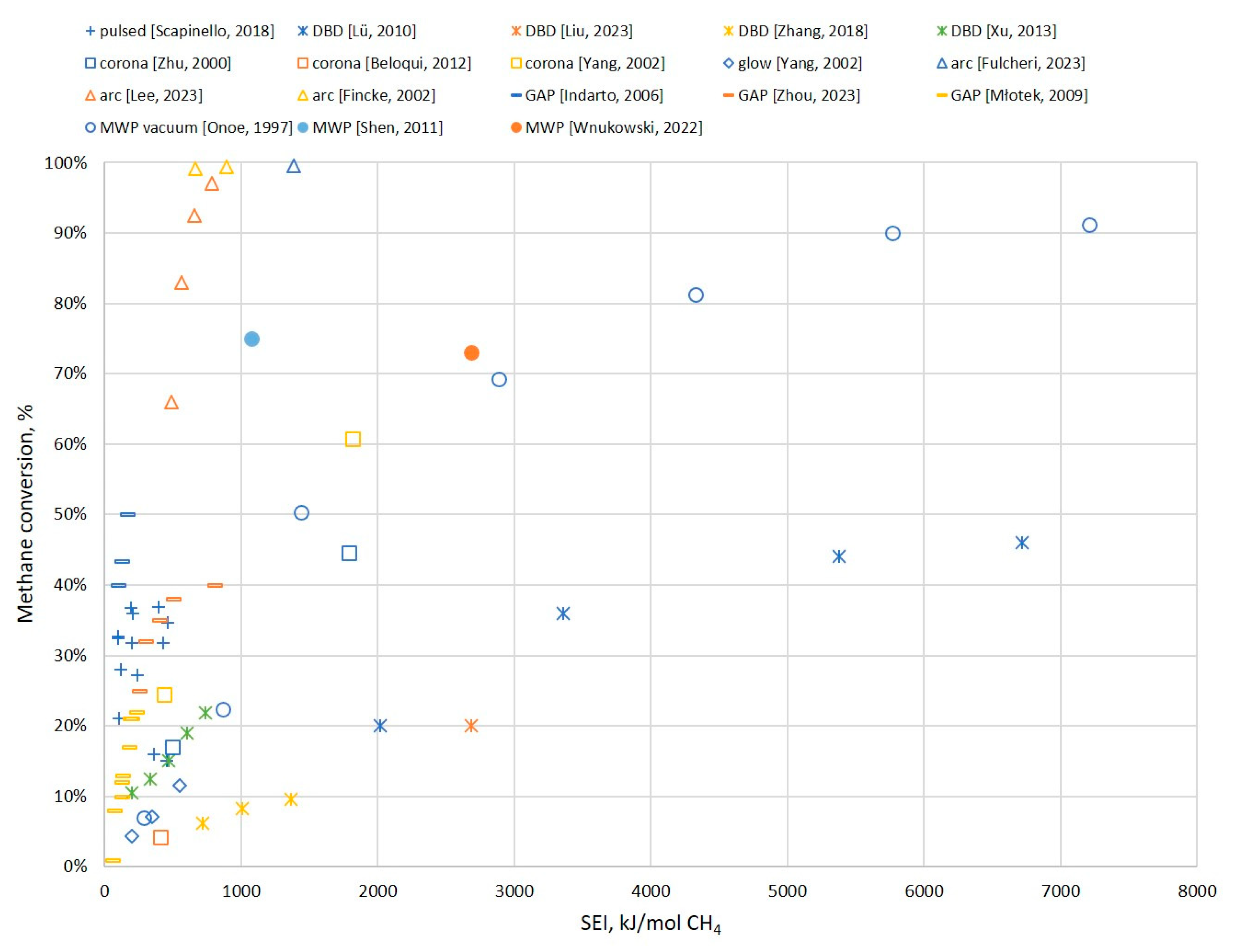
7.1. Conversion Rate

Figure 16 presents the conversion rate of methane depending on the specific energy input (SEI). The SEI is the ratio between the input power and the inlet stream of CH4 (in moles). The clear trend is that, with an increase in the SEI, the conversion rate increases as well. However, the most-desirable result is a high conversion rate with a relatively low SEI. Therefore, the closer to the upper-left corner of the chart, the better it is. With this assumption, it can be indicated that arc plasma and GAP show good conversion rates with relatively low energy consumption. On the opposite side, DBDs provide a relatively low conversion rate (lower than 50%) and require a significant amount of input power. Pulsed, corona, and MWP discharges are somewhere between. Pulsed plasma provides relatively low conversion, but with low input power. MWPs and corona plasmas can achieve high conversion rates, but at the cost of high input power.
While these results can be useful in estimating the potential conversion rates, they are not highly valuable on their own, as they do not involve the specifics of the products. A high input energy can be justified if the products show high market value. It should also be noted that this chart was designed to include a wide range of results for different types of plasma, but it certainly does not involve all cases. It is possible that better or worse results could be attributed to any of the involved discharges. The results included in the chart are based on the literature presented in Fig 9. These works provided enough data to calculate the SEI or it was given directly within the article. If the authors provided numerical values, then all of them are included in Figure 9. If the results were provided only in the chart, then only the extreme values are included in Figure 9. This approach was also carried out in the case of specific energy requirements (see Figure 11) and energy cost (see Figure 12).

7.2. Products Composition

Figure 17 presents the distribution of the products of major discharge types. Again, it should be noted that the chart presents only selected cases. However, they should clearly indicate some trends and distinguish different types of discharges. The “other” in the chart should be understood as carbon black/soot. While this is essentially a simplification and some other compounds might be involved in this group, e.g., benzene or C5 compounds, their share is usually small, and in most cases, the authors classified all the unidentified products as some carbonaceous material. From the figure, three general groups could be distinguished. The first one, DBD, is characterized by a high share of C2H6 and the presence of C3 and C4 hydrocarbons. The second group involves the remaining non-thermal plasmas, e.g., pulsed, corona, or glow, which can give different products depending on the conditions (SEI, pressure, addition of H2). The last group involves thermal and warm discharges, which provide mostly acetylene and carbon black. One exception is the vacuum MWP, which can be characterized by the distribution of the products typical for non-thermal plasma. This is due to the fact that, at low pressures, MWP shows a much-more-distinct non-equilibrium property [22]. The differences in the products derive from the discharge properties, which were discussed in the previous sections. It should be noted that the chart presents pure plasma cases, with no catalyst or a second-stage processing that can impact the final product distribution.

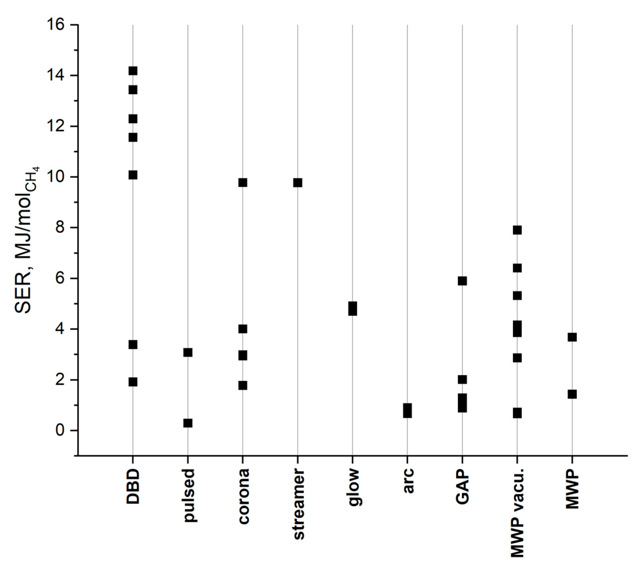
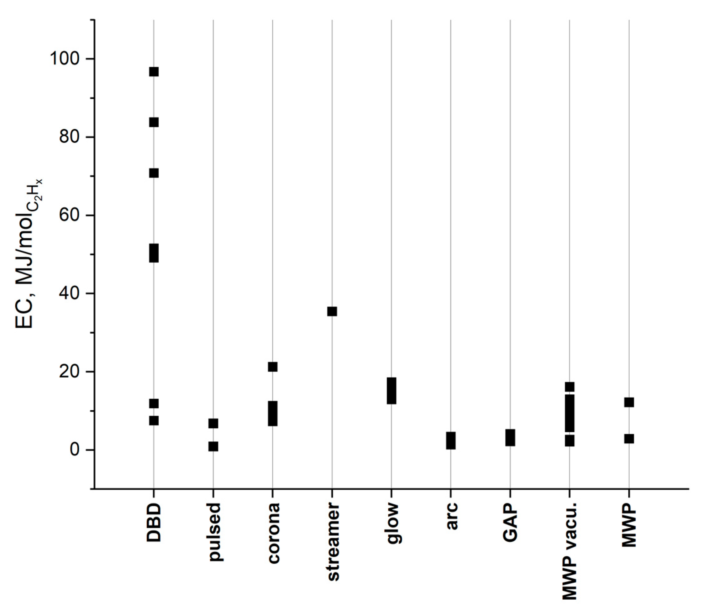
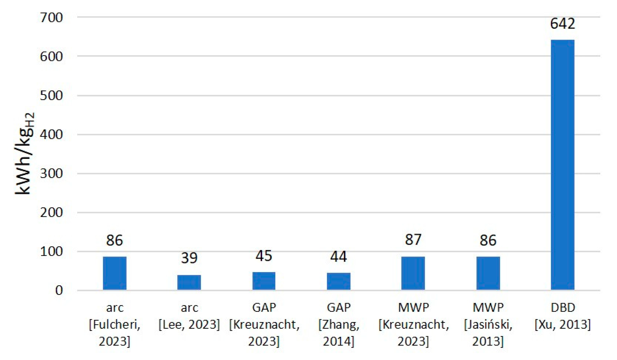
7.3. Energy Efficiency

Other indicators that can be used to compare plasma reactor performance are connected to the energy efficiency of the process. The specific energy requirement (SER) is the energy required to convert one mole of CH4. Some exemplary values for different plasmas are given in Figure 18. Energy cost (EC) is a parameter describing the energy required to produce one mole of a C2 compound. Exemplary values of EC are given in Figure 19. It should be noted that, very often, EC is given for a specific compound, e.g., C2H2 or C2H4. In the case of this work, the EC involves the sum of all the C2 compounds. These results partly coincide with the result from Figure 16 (as the SER and EC depend on the SEI): DBD plasma seems to be the least-effective, while arc, pulsed, and GAP plasmas show the highest efficiency. However, again, it should be emphasized that much depends on the products’ value. GAP and arc plasmas produce mostly C2H2 and carbon black, while pulsed plasma can give high shares of C2H4. Moreover, it should be noted that the energy efficiency parameters can be partly misleading. Very often, they involve only the electric energy that supplies the plasma torch. However, there are many other factors that might be energy-consuming and could be attributed to a specific type of discharge. For instance, arc plasma almost always requires a plasma agent, such as Ar, N2, or H2. However, their costs are never included. In the case of pressurized or vacuum systems, the costs of providing the demanded pressure are also usually omitted. In the case of MWP, it is not always indicated whether the input power is the absorbed microwaves or the supplied power. This is important, as contrary to other discharges, which show almost 100% efficiency of converting electric energy, 2.45 GHz microwave generators show ca. 65% efficiency.
Finally, when analyzing methane pyrolysis, it remains challenging not to mention hydrogen production, as it is typically the main motivation in considering this process. Figure 20 presents the energy efficiency of hydrogen production (energy requirement, in kWh, for the production of 1 kg of H2). The trend is very clear: the values are more or less in the same range for all the discharges that produce mostly carbon black and acetylene. In other words, due to deep dehydrogenation, these types of plasma can be characterized by a high output of hydrogen. In some cases, the energy efficiency of plasma systems is better than in the case of electrolysis, with n energy consumption of ca. 50 kWh/kgH2 for a PEM electrolyzer [118]. However, such a comparison does not include the fact of different substrates being used (H2O vs. CH4) and additional products obtained (O2 vs. carbon black/C2H2), which might be far more important for the final profitability of the process. On the contrary, DBD plasma, which requires a high SEI and produces mostly C2H6, shows significantly worse energy efficiency in terms of hydrogen production. However, it should be noted that hydrogen production is hardly ever considered as the main purpose of CH4 pyrolysis in the case of non-thermal plasmas and rarely do the articles involve any data on that matter.

7.4. Perspectives

Figure 21 shows the changes in the number of publications (included in this review), considering plasma pyrolysis of methane, within ca. 30 years. This period was divided into 5-year windows except for the last one, which additionally includes about half of 2023. It can be seen that, before the 2000s, the number of publications was relatively low. A significant increase occurred around the 2000s. Afterward, the number of publications was rather stable until very recently. The first increase in the years 1998–2002 is not obvious. It might have been affected by the increasing environmental awareness, which was strongly emphasized in the Kyoto Protocol from 1997. In fact, this issue is mentioned in the works of Finkce from 2002 [28,95]. On the other hand, other main authors of this period, i.e., Yao (2001–2002) [69,74,75,76] and Heintze (2002) [101,102], do not mention this issue. The background of their work was simply to develop a new efficient way of acetylene production. Interestingly, a significant share of only these three authors in the total number of publications from 1998–2002 (8 out of 13) might suggest that this peak of publications could have been just a coincidence. On the contrary, the period 2018–2023 shows much more diversity among the authors. In this case, it seems much more credible that the increased interest in plasma pyrolysis of methane is due to environmental awareness. Most of the publications from this period mention the problem of CO2 emissions and the need for H2 production.
In the author’s opinion, this trend is going to continue in the near future. Global efforts to switch the industry to hydrogen are one of the reasons. CO2-neutral methane pyrolysis could be one of the possible solutions. Matching it with the constantly increasing share of renewable energy in the energy market makes it even more appealing. Furthermore, in the context of the production of C2 olefins, plasma methane pyrolysis could be a promising alternative to classic crude oil cracking. Methane seems much more accessible than crude oil, and its pyrolysis is far more neutral in terms of CO2 emissions. The possibility of using biomethane makes the plasma pyrolysis process even more sustainable. All of these factors should result in a stable, if not increasing, interest in the process of methane plasma pyrolysis.
Right now, it is impossible to determine which type of plasma will play the main role in the development of the methane pyrolysis process. Thermal plasma seems to be in an advanced stage and is soon to become a commercial process. The question is of the potential demand. Taking into account recent years, it seems that strictly non-thermal plasmas are losing interest, with the one exception of DBD plasma. Nevertheless, right now, it is the warm plasma (i.e., pulse, GAP, and MW) that seems the most promising in terms of C2 olefins production, and the author expects further studies in that field.
Although the present circumstances are favorable for the further development of methane plasma pyrolysis, there are a few bottlenecks that must be solved to switch the scale from laboratory to commercial. The first is the energy cost. Even for the most-developed thermal plasmas, the costs of H2 production are at best close to water electrolysis. Carbon black production might compensate for some of the costs, especially if new applications, such as carbon-based vanadium redox flow batteries, are considered [119,120], but the market capacity for this product is rather limited. The formation of carbon black is a problematic issue on its own. The presence of carbon deposits is problematic for all electrode reactors, as well as for the MW plasma reactors. Shifting the production from carbon black to C2 olefins could be a desired approach. However, this process is at a much earlier stage, and more studies are still needed to focus on increasing the process’s energy efficiency and selectivity. Another potential issue to overcome might be the completely different structure of the potential process facilities compared to the present ones. Whether the product is hydrogen or olefins, these products are produced on a large, centralized scale. Using plasma, sourced with renewable energy and/or biomethane, would be rather based on small-scale, local start-ups. This will not allow for a quick replacement of the classic industry processes.

7.5. Conclusions

This article gives a brief description of the plasma reactors that are most commonly used in the context of methane pyrolysis and characterizes the products of this process. A short summarization of the performance of the most-widely used reactor types is given in Table 1.
An obvious conclusion is that plasma reactors provide a vast opportunity due to a wide range of possible products. For the same reason, it is hard to compare different types of discharges. However, some general trends can be emphasized:
-
Pyrolyzing methane into hydrogen and carbon black, with the use of arc plasma reactors, is a mature and relatively efficient technology. However, limited demand for carbon black might be a limiting factor.
-
Non-equilibrium and warm plasmas give the potential for the simultaneous production of hydrogen and C2 compounds. However, the more hydrogenated the C2 compounds are, the less effective the hydrogen production.
-
Ethylene seems to be the most-valuable product as an important chemical substrate, yet its production is not as straightforward as in the case of ethane or acetylene. Some of the modifications that could enhance the process are: two-stage processes, catalyst application, and hydrogen addition.
-
High carbon black selectivity might be problematic in all cases, as its presence may lead to the erosion of electrodes, problems with plasma stability, and catalyst deactivation. Strategies mitigating this issue might be necessary for the further development of plasma methane pyrolysis technologies.
-
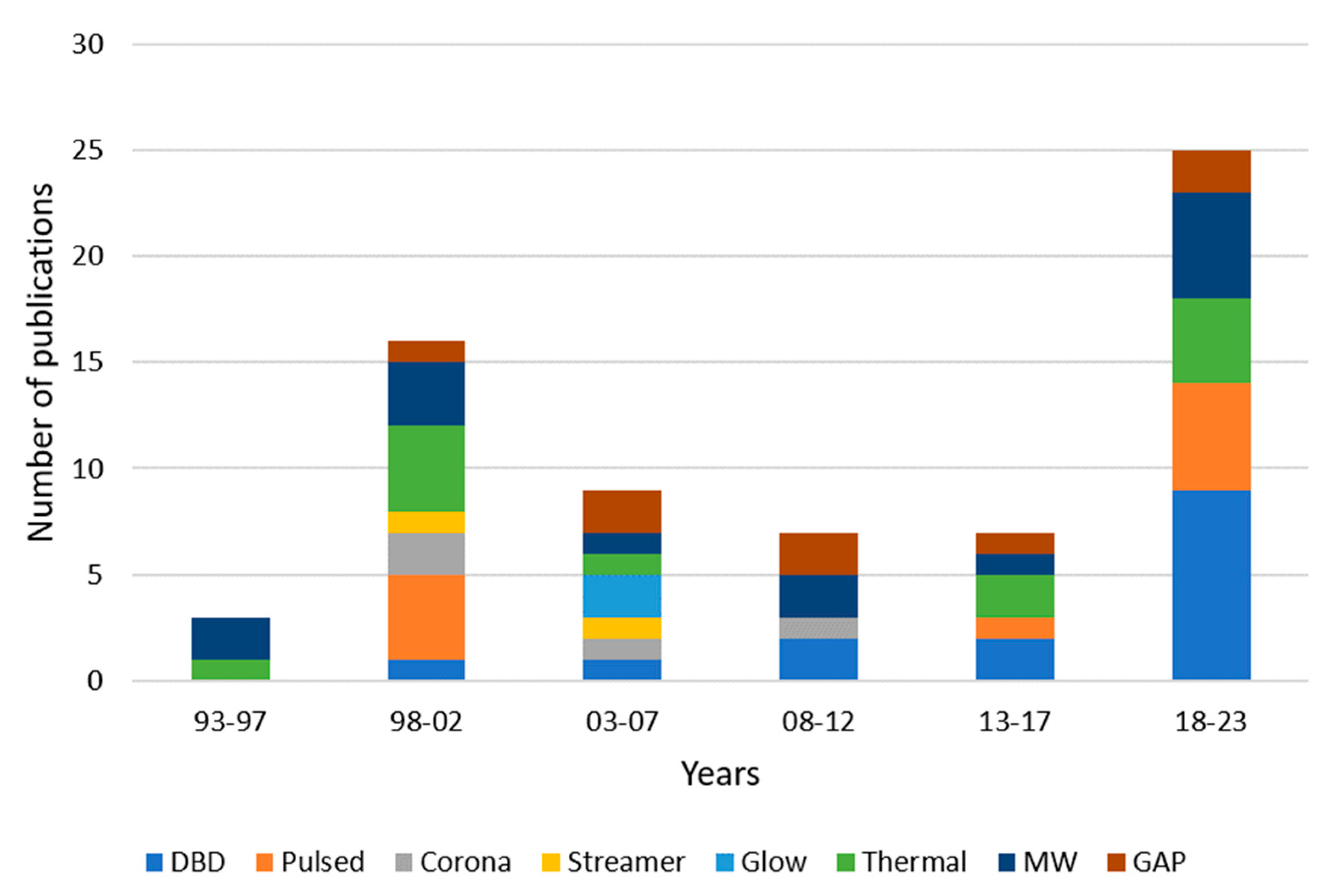
The increasing number of articles on the topic of methane plasma pyrolysis and favorable political circumstances may suggest that this technology will develop. Recent research work indicates that DBD, warm plasmas (MWP, GAP, and pulsed spark), and arc plasma will be the main reactor types for further development and investigation.

Funding

This research received no external funding.

Data Availability Statement

No new data were created nor analyzed in this study. Data sharing is not applicable to this article.

Conflicts of Interest

The author declares no conflict of interest.

References

  1. Cheon, S.; Byun, M.; Lim, D.; Lee, H.; Lim, H. Parametric study for thermal and catalytic methane pyrolysis for hydrogen production: Techno-economic and scenario analysis. Energies 2021, 14, 6102. [Google Scholar] [CrossRef]
  2. Wróbel, K.; Wróbel, J.; Tokarz, W.; Lach, J.; Podsadni, K.; Czerwiński, A. Hydrogen internal combustion engine vehicles: A review. Energies 2022, 15, 8937. [Google Scholar] [CrossRef]
  3. Manoharan, Y.; Hosseini, S.E.; Butler, B.; Alzhahrani, H.; Senior, B.T.F.; Ashuri, T.; Krohn, J. Hydrogen fuel cell vehicles; current status and future prospect. Appl. Sci. 2019, 9, 2296. [Google Scholar] [CrossRef]
  4. Böhm, M.; Fernández Del Rey, A.; Pagenkopf, J.; Varela, M.; Herwartz-Polster, S.; Nieto Calderón, B. Review and comparison of worldwide hydrogen activities in the rail sector with special focus on on-board storage and refueling technologies. Int. J. Hydrogen Energy 2022, 47, 38003–38017. [Google Scholar] [CrossRef]
  5. Caramanico, N.; Di Florio, G.; Baratto, M.C.; Cigolotti, V.; Basosi, R.; Busi, E. Economic analysis of hydrogen household energy systems including incentives on energy communities and externalities: A case study in Italy. Energies 2021, 14, 5847. [Google Scholar] [CrossRef]
  6. Sandri, O.; Holdsworth, S.; Hayes, J.; Willand, N.; Moore, T. Hydrogen for all? Household energy vulnerability and the transition to hydrogen in Australia. Energy Res. Soc. Sci. 2021, 79, 102179. [Google Scholar] [CrossRef]
  7. Badea, N.I. Hydrogen as energy sources—Basic concepts. Energies 2021, 14, 5783. [Google Scholar] [CrossRef]
  8. Bhaskar, A.; Assadi, M.; Somehsaraei, H.N. Can methane pyrolysis based hydrogen production lead to the decarbonisation of iron and steel industry? Energy Convers. Manag. X 2021, 10, 100079. [Google Scholar] [CrossRef]
  9. Chen, G.; Tu, X.; Homm, G.; Weidenkaff, A. Plasma pyrolysis for a sustainable hydrogen economy. Nat. Rev. Mater. 2022, 7, 333–334. [Google Scholar] [CrossRef]
  10. Sánchez-Bastardo, N.; Schlögl, R.; Ruland, H. Methane pyrolysis for zero-emission hydrogen production: A potential bridge technology from fossil fuels to a renewable and sustainable hydrogen economy. Ind. Eng. Chem. Res. 2021, 60, 11855–11881. [Google Scholar] [CrossRef]
  11. Bui, M.; Adjiman, C.S.; Bardow, A.; Anthony, E.J.; Boston, A.; Brown, S.; Fennell, P.S.; Fuss, S.; Galindo, A.; Hackett, L.A.; et al. Carbon capture and storage (CCS): The way forward. Energy Environ. Sci. 2018, 11, 1062–1176. [Google Scholar] [CrossRef]
  12. Zavarkó, M.; Imre, A.R.; Pörzse, G.; Csedő, Z. Past, present and near future: An overview of closed, running and planned biomethanation facilities in Europe. Energies 2021, 14, 5591. [Google Scholar] [CrossRef]
  13. Rogala, Z.; Stanclik, M.; Łuszkiewicz, D. Perspectives for the use of biogas and biomethane in the context of the green energy transformation on the example of an eu country. Energies 2023, 16, 1911. [Google Scholar] [CrossRef]
  14. Daliah, R. Technology Landscape: Key Players in Plastic Pyrolysis. 2021. Available online: https://www.luxresearchinc.com/blog/technology-landscape-key-players-in-methane-pyrolysis/ (accessed on 10 March 2023).
  15. Schneider, S.; Bajohr, S.; Graf, F.; Kolb, T. State of the art of hydrogen production via pyrolysis of natural gas. ChemBioEng. Rev. 2020, 7, 150–158. [Google Scholar] [CrossRef]
  16. Raza, J.; Khoja, A.H.; Anwar, M.; Saleem, F.; Naqvi, S.R.; Liaquat, R.; Hassan, M.; Javaid, R.; Qazi, U.M.; Lumbers, B. Methane decomposition for hydrogen production: A comprehensive review on catalyst selection and reactor systems. Renew. Sustain. Energy Rev. 2022, 168, 112774. [Google Scholar] [CrossRef]
  17. Msheik, M.; Rodat, S.; Abanades, S. Methane cracking for hydrogen production: A review of catalytic and molten media pyrolysis. Energies 2021, 14, 3107. [Google Scholar] [CrossRef]
  18. Korányi, T.I.; Németh, M.; Beck, A.; Horváth, A. Recent advances in methane pyrolysis: Turquoise hydrogen with solid carbon production. Energies 2022, 15, 6342. [Google Scholar] [CrossRef]
  19. Patlolla, S.R.; Katsu, K.; Sharafian, A.; Wei, K.; Herrera, O.E.; Mérida, W. A review of methane pyrolysis technologies for hydrogen production. Renew. Sustain. Energy Rev. 2023, 181, 113323. [Google Scholar] [CrossRef]
  20. Amghizar, I.; Vandewalle, L.A.; Van Geem, K.M.; Marin, G.B. New trends in olefin production. Engineering 2017, 3, 171–178. [Google Scholar] [CrossRef]
  21. Gholami, Z.; Gholami, F.; Tišler, Z.; Tomas, M.; Vakili, M. A review on production of light olefins via fluid catalytic cracking. Energies 2021, 14, 1089. [Google Scholar] [CrossRef]
  22. Minea, T.; van den Bekerom, D.C.M.; Peeters, F.J.J.; Zoethout, E.; Graswinckel, M.F.; van de Sanden, M.C.M.; Cents, T.; Lefferts, L.; van Rooij, G.J. Non-oxidative methane coupling to C2 hydrocarbons in a microwave plasma reactor. Plasma Process. Polym. 2018, 15, 1–16. [Google Scholar] [CrossRef]
  23. Scapinello, M.; Delikonstantis, E.; Stefanidis, G.D. The panorama of plasma-assisted non-oxidative methane reforming. Chem. Eng. Process. Process. Intensif. 2017, 117, 120–140. [Google Scholar] [CrossRef]
  24. Fincke, J.R.; Anderson, R.P.; Hyde, T.; Wright, R.; Bewley, R.; Haggard, D.C.; Swank, W.D. Thermal Conversion of Methane to Acetylene Final Report; Idaho National Lab.: Idaho Falls, ID, USA, 2000. [Google Scholar]
  25. Lee, D.H.; Kang, H.; Kim, Y.; Song, H.; Lee, H.; Choi, J.; Kim, K.-T.; Song, Y.-H. Plasma-assisted hydrogen generation: A mechanistic review. Fuel. Process. Technol. 2023, 247, 107761. [Google Scholar] [CrossRef]
  26. Feng, J.; Sun, X.; Li, Z.; Hao, X.; Fan, M.; Ning, P.; Li, K. Plasma-assisted reforming of methane. Adv. Sci. 2022, 9, 2203221. [Google Scholar] [CrossRef] [PubMed]
  27. Nozaki, T.; Okazaki, K. Non-thermal plasma catalysis of methane: Principles, energy efficiency, and applications. Catal. Today 2013, 211, 29–38. [Google Scholar] [CrossRef]
  28. Fincke, J.R.; Anderson, R.P.; Hyde, T.A.; Detering, B.A. Plasma pyrolysis of methane to hydrogen and carbon black. Ind. Eng. Chem. Res. 2002, 41, 1425–1435. [Google Scholar] [CrossRef]
  29. Dors, M.; Nowakowska, H.; Jasiński, M.; Mizeraczyk, J. Chemical kinetics of methane pyrolysis in microwave plasma at atmospheric pressure. Plasma Chem. Plasma Process 2014, 34, 313–326. [Google Scholar] [CrossRef]
  30. Guo, X.; Fang, G.; Li, G.; Ma, H.; Fan, H.; Yu, L.; Ma, C.; Wu, X.; Deng, D.; Wei, M.; et al. Direct, nonoxidative conversion of methane to ethylene, aromatics, and hydrogen. Science 2014, 344, 616–619. [Google Scholar] [CrossRef] [PubMed]
  31. Kreuznacht, S.; Purcel, M.; Böddeker, S.; Awakowicz, P.; Xia, W.; Muhler, M.; Boke, M.; von Keudell, A. Comparison of the performance of a microwave plasma torch and a gliding arc plasma for hydrogen production via methane pyrolysis. Plasma Process Polym. 2023, 20, 2200132. [Google Scholar] [CrossRef]
  32. Jamróz, P.; Kordylewski, W.; Wnukowski, M. Microwave plasma application in decomposition and steam reforming of model tar compounds. Fuel Process. Technol. 2018, 169, 1–14. [Google Scholar] [CrossRef]
  33. Cuoci, A.; Frassoldati, A.; Faravelli, T.; Ranzi, E. A computational tool for the detailed kinetic modeling of laminar flames: Application to C2H4/CH4 coflow flames. Combust. Flame 2013, 160, 870–886. [Google Scholar] [CrossRef]
  34. Zhang, H.; Wang, W.; Li, X.; Han, L.; Yan, M.; Zhong, Y.; Tu, X. Plasma activation of methane for hydrogen production in a N2 rotating gliding arc warm plasma: A chemical kinetics study. Chem. Eng. J. 2018, 345, 67–78. [Google Scholar] [CrossRef]
  35. Keramiotis, C.; Vourliotakis, G.; Skevis, G.; Founti, M.A.; Esarte, C.; Sánchez, N.E.; Millera, A.; Bilbao, R.; Alzueta, M.U. Experimental and computational study of methane mixtures pyrolysis in a flow reactor under atmospheric pressure. Energy 2012, 43, 103–110. [Google Scholar] [CrossRef]
  36. Wnukowski, M.; van de Steeg, A.W.; Hrycak, B.; Jasiński, M.; van Rooij, G.J. Influence of hydrogen addition on methane coupling in a moderate pressure microwave plasma. Fuel 2021, 288, 119674. [Google Scholar] [CrossRef]
  37. Scapinello, M.; Delikonstantis, E.; Stefanidis, G.D. A study on the reaction mechanism of non-oxidative methane coupling in a nanosecond pulsed discharge reactor using isotope analysis. Chem. Eng. J. 2019, 360, 64–74. [Google Scholar] [CrossRef]
  38. Butterworth, T.; Van Den Steeg, A.; Van Den Bekerom, D.; Minea, T.; Righart, T.; Ong, Q. Plasma induced vibrational excitation of CH4—A window to its mode selective processing. Plasma Sources Sci. Technol. 2020, 29, 1–34. [Google Scholar] [CrossRef]
  39. Butterworth, T.D.; Amyay, B.; Bekerom, D.V.D.; Steeg, A.V.D.; Minea, T.; Gatti, N.; Ong, Q.; Richard, C.; van Kruijsdijk, C.; Smits, J.T.; et al. Quantifying methane vibrational and rotational temperature with Raman scattering. J. Quant. Spectrosc. Radiat. Transf. 2019, 236, 106562. [Google Scholar] [CrossRef]
  40. Heijkers, S.; Aghaei, M.; Bogaerts, A. Plasma-based CH4 conversion into higher hydrocarbons and H2: Modeling to reveal the reaction mechanisms of different plasma sources. J. Phys. Chem. C 2020, 124, 7016–7030. [Google Scholar] [CrossRef]
  41. Fridman, A. Introduction to Theoretical and Applied Plasma Chemistry—Plasma Chemistry; Cambridge University Press: Cambridge, UK, 2008. [Google Scholar]
  42. Meichsner, J.; Schmidt, M.; Schneider, R.; Wganer, H.-E. Introduction. In Nonthermal Plasma Chemistry and Physics; Meichsner, J., Ed.; CRC Press: Boca Raton, FL, USA, 2013. [Google Scholar]
  43. Meichsner, J.; Schmidt, M.; Schneider, R.; Wganer, H.-E. Thermal and nonthermal plasmas. In Nonthermal Plasma Chemistry and Physics; Meichsner, J., Ed.; CRC Press: Boca Raton, FL, USA, 2013. [Google Scholar]
  44. Tendero, C.; Tixier, C.; Tristant, P.; Desmaison, J.; Leprince, P. Atmospheric pressure plasmas: A review. Spectrochim. Acta Part B At. Spectrosc. 2006, 61, 2–30. [Google Scholar] [CrossRef]
  45. Zhang, H.; Du, C.; Wu, A.; Bo, Z.; Yan, J.; Li, X. Rotating gliding arc assisted methane decomposition in nitrogen for hydrogen production. Int. J. Hydrogen Energy 2014, 39, 12620–12635. [Google Scholar] [CrossRef]
  46. Boselli, M.; Colombo, V.; Ghedini, E.; Gherardi, M.; Laurita, R.; Liguori, A.; Sanibondi, P.; Stancampiano, A. Study of the role of dielectric material in a dielectric barrier discharge (DBD) plasma source for dermatological applications. In Proceedings of the IEEE International Conference on Solid Dielectrics, Bologna, Italy, 30 June–4 July 2013; pp. 595–598. [Google Scholar] [CrossRef]
  47. Khoja, A.H.; Tahir, M.; Amin, N.A.S. Recent developments in non-thermal catalytic DBD plasma reactor for dry reforming of methane. Energy Convers. Manag. 2019, 183, 529–560. [Google Scholar] [CrossRef]
  48. Snoeckx, R.; Setareh, M.; Aerts, R.; Simon, P.; Maghari, A.; Bogaerts, A. Influence of N2 concentration in a CH4/N2 dielectric barrier discharge used for CH4 conversion into H2. Int. J. Hydrogen Energy 2013, 38, 16098–16120. [Google Scholar] [CrossRef]
  49. Xu, C.; Tu, X. Plasma-assisted methane conversion in an atmospheric pressure dielectric barrier discharge reactor. J. Energy Chem. 2013, 22, 420–425. [Google Scholar] [CrossRef]
  50. Taheraslani, M.; Gardeniers, H. Coupling of CH4 to C2 hydrocarbons in a packed bed DBD plasma reactor: The effect of dielectric constant and porosity of the packing. Energies 2020, 13, 468. [Google Scholar] [CrossRef]
  51. Kim, J.; Jeoung, J.; Jeon, J.; Kim, J.; Mok, Y.S.; Ha, K.S. Effects of dielectric particles on non-oxidative coupling of methane in a dielectric barrier discharge plasma reactor. Chem. Eng. J. 2019, 377, 119896. [Google Scholar] [CrossRef]
  52. Taheraslani, M.; Gardeniers, H. Plasma catalytic conversion of CH4 to alkanes, olefins and H2 in a packed bed DBD reactor. Processes 2020, 8, 774. [Google Scholar] [CrossRef]
  53. Zhang, S.; Gao, Y.; Sun, H.; Bai, H.; Wang, R.; Shao, T. Time-resolved characteristics and chemical kinetics of non-oxidative methane conversion in repetitively pulsed dielectric barrier discharge plasmas. J. Phys. D. Appl. Phys. 2018, 51, 274005. [Google Scholar] [CrossRef]
  54. Liu, R.; Hao, Y.; Wang, T.; Wang, L.; Bogaerts, A.; Guo, H.; Yi, Y. Hybrid plasma-thermal system for methane conversion to ethylene and hydrogen. Chem. Eng. J. 2023, 463, 142442. [Google Scholar] [CrossRef]
  55. Górska, A.; Krawczyk, K.; Jodzis, S.; Schmidt-Szałowski, K. Non-oxidative methane coupling using Cu/ZnO/Al2O3 catalyst in DBD. Fuel 2011, 90, 1946–1952. [Google Scholar] [CrossRef]
  56. Chen, H.L.; Lee, H.M.; Chen, S.H.; Chao, Y.; Chang, M.B. Review of plasma catalysis on hydrocarbon reforming for hydrogen production-Interaction, integration, and prospects. Appl. Catal. B Environ. 2008, 85, 1–9. [Google Scholar] [CrossRef]
  57. Lü, J.; Li, Z. Conversion of natural gas to C2 hydrocarbons via cold plasma technology. J. Nat. Gas Chem. 2010, 19, 375–379. [Google Scholar] [CrossRef]
  58. Boutot, T.; Buckle, K.; Collins, F.; Fletcher, D.; Frontain, E.; Kozinski, J.; Lister, D.; Lin, H.; Liu, Z.; Mendoza, G.; et al. High-concentration hydrogen production from natural gas using a pulsed dielectric barrier discharge. In Proceedings of the Hydrogen Fuel Cells 2004, Toronto, ON, Canada, 25–28 September 2004. [Google Scholar]
  59. Liu, L.; Das, S.; Zhang, Z.; Kawi, S. Nonoxidative coupling of methane over ceria-supported single-atom pt catalysts in DBD plasma. ACS Appl. Mater. Interfaces 2022, 14, 5363–5375. [Google Scholar] [CrossRef]
  60. Mao, X.; Chen, Q.; Guo, C. Methane pyrolysis with N2/Ar/He diluents in a repetitively-pulsed nanosecond discharge: Kinetics development for plasma assisted combustion and fuel reforming. Energy Convers. Manag. 2019, 200, 112018. [Google Scholar] [CrossRef]
  61. Thanyachotpaiboon, K.; Chavadej, S.; Caldwell, T.A.; Lobban, L.L.; Mallinson, R.G. Conversion of methane to higher hydrocarbons in AC nonequilibrium plasmas. AIChE J. 1998, 44, 2252–2257. [Google Scholar] [CrossRef]
  62. García-Moncada, N.; van Rooij, G.; Cents, T.; Lefferts, L. Catalyst-assisted DBD plasma for coupling of methane: Minimizing carbon-deposits by structured reactors. Catal. Today 2021, 369, 210–220. [Google Scholar] [CrossRef]
  63. Chawdhury, P.; Bhanudas Rawool, S.; Umamaheswara Rao, M.; Subrahmanyam, C. Methane decomposition by plasma-packed bed non-thermal plasma reactor. Chem. Eng. Sci. 2022, 258, 117779. [Google Scholar] [CrossRef]
  64. Yang, Y. Methane conversion and reforming by nonthermal plasma on pins. Ind. Eng. Chem. Res. 2002, 41, 5918–5926. [Google Scholar] [CrossRef]
  65. Pai, D.Z.; Lacoste, D.A.; Laux, C.O. Transitions between corona, glow, and spark regimes of nanosecond repetitively pulsed discharges in air at atmospheric pressure. J. Appl. Phys. 2010, 107, 093303. [Google Scholar] [CrossRef]
  66. Kado, S.; Sekine, Y.; Urasaki, K.; Okazaki, K.; Nozaki, T. High performance methane conversion into valuable products with spark discharge at room temperature. Stud. Surf. Sci. Catal. 2004, 147, 577–582. [Google Scholar] [CrossRef]
  67. Li, X.S.; Zhu, A.M.; Wang, K.J.; Xu, Y.; Song, Z.M. Methane conversion to C2 hydrocarbons and hydrogen in atmospheric non-thermal plasmas generated by different electric discharge techniques. Catal. Today 2004, 98, 617–624. [Google Scholar] [CrossRef]
  68. Nijdam, S.; Teunissen, J.; Ebert, U. The physics of streamer discharge phenomena. Plasma Sources Sci. Technol. 2020, 29, 103001. [Google Scholar] [CrossRef]
  69. Yao, S.L.; Suzuki, E.; Meng, N.; Nakayama, A. A high-efficiency reactor for the pulsed plasma conversion of methane. Plasma Chem. Plasma Process. 2002, 22, 225–237. [Google Scholar] [CrossRef]
  70. Scapinello, M.; Delikonstantis, E.; Stefanidis, G.D. Direct methane-to-ethylene conversion in a nanosecond pulsed discharge. Fuel 2018, 222, 705–710. [Google Scholar] [CrossRef]
  71. Delikonstantis, E.; Scapinello, M.; Stefanidis, G.D. Low energy cost conversion of methane to ethylene in a hybrid plasma-catalytic reactor system. Fuel Process. Technol. 2018, 176, 33–42. [Google Scholar] [CrossRef]
  72. Morais, E.; Delikonstantis, E.; Scapinello, M.; Smith, G.; Stefanidis, G.D.; Bogaerts, A. Methane coupling in nanosecond pulsed plasmas: Correlation between temperature and pressure and effects on product selectivity. Chem. Eng. J. 2023, 462, 142227. [Google Scholar] [CrossRef]
  73. Lotfalipour, R.; Ghorbanzadeh, A.M.; Mahdian, A. Methane conversion by repetitive nanosecond pulsed plasma. J. Phys. D. Appl. Phys. 2014, 47, 365201. [Google Scholar] [CrossRef]
  74. Yao, S.L.; Suzuki, E.; Nakayama, A. The pyrolysis property of a pulsed plasma of methane. Plasma Chem. Plasma Process. 2001, 21, 651–663. [Google Scholar] [CrossRef]
  75. Yao, S.; Nakayama, A.; Suzuki, E. Methane conversion using a high-frequency pulsed plasma: Discharge Features. AIChE J. 2001, 47, 419–426. [Google Scholar] [CrossRef]
  76. Yao, S.; Nakayama, A.; Suzuki, E. Methane conversion using a high-frequency pulsed plasma: Important factors. AIChE J. 2001, 47, 413–418. [Google Scholar] [CrossRef]
  77. Delikonstantis, E.; Scapinello, M.; Van Geenhoven, O.; Stefanidis, G.D. Nanosecond pulsed discharge-driven non-oxidative methane coupling in a plate-to-plate electrode configuration plasma reactor. Chem. Eng. J. 2020, 380, 122477. [Google Scholar] [CrossRef]
  78. Zhu, A.; Gong, W.; Zhang, X.; Zhang, B. Coupling of methane under pulse corona plasma (I)—In the absence of oxygen. Sci. China Ser. B Chem. 2000, 43, 208–214. [Google Scholar] [CrossRef]
  79. Beloqui Redondo, A.; Troussard, E.; Van Bokhoven, J.A. Non-oxidative methane conversion assisted by corona discharge. Fuel Process. Technol. 2012, 104, 265–270. [Google Scholar] [CrossRef]
  80. Dai, B.; Zhang, X.L.; Gong, W.M.; He, R. Effects of hydrogen on the methane coupling under non-equilibrium plasma. Plasma Sci. Technol. 2001, 3, 637–639. [Google Scholar] [CrossRef]
  81. Dai, W.; Yu, H.; Chen, Q.; Yin, Y.; Dai, X. Methane conversion to C2 hydrocarbons by abnormal glow discharge at atmospheric pressure. Plasma Sci. Technol. 2005, 7, 3132–3134. [Google Scholar] [CrossRef]
  82. Patiño, P.; Pérez, Y.; Caetano, M. Coupling and reforming of methane by means of low pressure radio-frequency plasmas. Fuel 2005, 84, 2008–2014. [Google Scholar] [CrossRef]
  83. Majidi Bidgoli, A.; Ghorbanzadeh, A.; Lotfalipour, R.; Roustaei, E.; Zakavi, M. Gliding spark plasma: Physical principles and performance in direct pyrolysis of methane. Energy 2017, 125, 705–715. [Google Scholar] [CrossRef]
  84. Bae, J.; Lee, M.; Park, S.; Jeong, M.G.; Hong, D.Y.; Kim, Y.D.; Park, Y.-K.; Hwang, Y.K. Investigation of intermediates in non-oxidative coupling of methane by non-thermal RF plasma. Catal. Today 2017, 293, 105–112. [Google Scholar] [CrossRef]
  85. Kuznetsov, D.L.; Uvarin, V.V.; Filatov, I.E. Plasma chemical conversion of methane by pulsed electron beams and non-self-sustained discharges. J. Phys. D Appl. Phys. 2021, 54, 435203. [Google Scholar] [CrossRef]
  86. Raja, R.B.; Sarathi, R.; Vinu, R. Selective production of hydrogen and solid carbon via methane pyrolysis using a swirl-induced point–plane non-thermal plasma reactor. Energy Fuels 2022, 36, 826–836. [Google Scholar] [CrossRef]
  87. Erdogan, A.A.; Yilmazoglu, M.Z. Plasma gasification of the medical waste. Int. J. Hydrog. Energy 2021, 46, 29108–29125. [Google Scholar] [CrossRef]
  88. Fulcheri, L.; Rohani, V.J.; Wyse, E.; Hardman, N.; Dames, E. An energy-efficient plasma methane pyrolysis process for high yields of carbon black and hydrogen. Int. J. Hydrogen Energy 2023, 48, 2920–2928. [Google Scholar] [CrossRef]
  89. Gautier, M.; Rohani, V.; Fulcheri, L. Direct decarbonization of methane by thermal plasma for the production of hydrogen and high value-added carbon black. Int. J. Hydrogen Energy 2017, 42, 28140–28156. [Google Scholar] [CrossRef]
  90. Fulcheri, L.; Schwob, Y. From methane to hydrogen, carbon black and water. Int. J. Hydrog. Energy 1995, 20, 197–202. [Google Scholar] [CrossRef]
  91. Ravary, B.; Fulcheri, L.; Bakken, J.A.; Flamant, G.; Fabry, F. Influence of the electromagnetic forces on momentum and heat transfer in a 3-phase ac plasma reactor. Plasma Chem. Plasma Process 1999, 19, 69–89. [Google Scholar] [CrossRef]
  92. Fulcheri, L.; Probst, N.; Flamant, G.; Fabry, F.; Grivei, E.; Bourrat, X. Plasma processing: A step towards the production of new grades of carbon black. Carbon 2002, 40, 169–176. [Google Scholar] [CrossRef]
  93. Kim, K.S.; Seo, J.H.; Nam, J.S.; Ju, W.T.; Hong, S.H. Production of hydrogen and carbon black by methane decomposition using DC-RF hybrid thermal plasmas. IEEE Trans. Plasma Sci. 2005, 33, 813–823. [Google Scholar]
  94. Mašláni, A.; Hrabovský, M.; Křenek, P.; Hlína, M.; Raman, S.; Sikarwar, V.S.; Jeremias, M. Pyrolysis of methane via thermal steam plasma for the production of hydrogen and carbon black. Int. J. Hydrog. Energy 2021, 46, 1605–1614. [Google Scholar] [CrossRef]
  95. Fincke, J.R.; Anderson, R.P.; Hyde, T.; Detering, B.A.; Wright, R.; Bewley, R.L.; Haggard, D.C.; Swank, W.D. Plasma thermal conversion of methane to acetylene. Plasma Chem. Plasma Process. 2002, 22, 105–136. [Google Scholar] [CrossRef]
  96. An, H.; Cheng, Y.; Li, T.; Li, Y.; Cheng, Y. Numerical analysis of methane pyrolysis in thermal plasma for selective synthesis of acetylene. Fuel Process. Technol. 2018, 172, 195–199. [Google Scholar] [CrossRef]
  97. Lee, Y.H.; Oh, J.H.; Choi, S. Evaluation of process conditions for methane pyrolysis applying the triple thermal plasma system. Int. J. Hydrog. Energy 2023, 48, 27127–27136. [Google Scholar] [CrossRef]
  98. Li, T.; Rehmet, C.; Cheng, Y.; Jin, Y.; Cheng, Y. Experimental comparison of methane pyrolysis in thermal plasma. Plasma Chem. Plasma Process. 2017, 37, 1033–1049. [Google Scholar] [CrossRef]
  99. Jasiński, M.; Czylkowski, D.; Hrycak, B.; Dors, M.; Mizeraczyk, J. Atmospheric pressure microwave plasma source for hydrogen production. Int. J. Hydrog. Energy 2013, 38, 11473–11483. [Google Scholar] [CrossRef]
  100. Chun, S.M.; Hong, Y.C.; Choi, D.H. Reforming of methane to syngas in a microwave plasma torch at atmospheric pressure. J. CO2 Util. 2017, 19, 221–229. [Google Scholar] [CrossRef]
  101. Heintze, M.; Magureanu, M.; Kettlitz, M. Mechanism of C2 hydrocarbon formation from methane in a pulsed microwave plasma. J. Appl. Phys. 2002, 92, 7022–7031. [Google Scholar] [CrossRef]
  102. Heintze, M.; Magureanu, M. Methane conversion into acetylene in a microwave plasma: Optimization of the operating parameters. J. Appl. Phys. 2002, 92, 2276–2283. [Google Scholar] [CrossRef]
  103. Onoe, K.; Fujie, A.; Yamaguchi, T.; Hatano, Y. Selective synthesis of acetylene from methane by microwave plasma reactions. Fuel 1997, 76, 281–282. [Google Scholar] [CrossRef]
  104. Cho, W.; Lee, S.H.; Ju, W.S.; Baek, Y.; Lee, J.K. Conversion of natural gas to hydrogen and carbon black by plasma and application of plasma carbon black. Catal. Today 2004, 98, 633–638. [Google Scholar] [CrossRef]
  105. Suib, S.L.; Zerger, R.P. A direct, continuous, low-power catalytic conversion of methane to higher hydrocarbons via microwave plasmas. J. Catal. 1993, 139, 383–391. [Google Scholar] [CrossRef]
  106. Zhang, J.Q.; Yang, Y.J.; Zhang, J.S.; Liu, Q.; Tan, K.R. Non-oxidative coupling of methane to C2 hydrocarbons under above-atmospheric pressure using pulsed microwave plasma. Energy Fuels 2002, 16, 687–693. [Google Scholar] [CrossRef]
  107. Vander Wal, R.; Sengupta, A.; Musselman, E.; Skoptsov, G. Microwave-Driven Plasma-Mediated Methane Cracking: Product Carbon Characterization. C 2018, 4, 61. [Google Scholar] [CrossRef]
  108. Wnukowski, M.; Jamróz, P.; Niedzwiecki, L. The role of hydrogen in microwave plasma valorization of producer gas. Int. J. Hydrog. Energy 2021, 48, 11640–11651. [Google Scholar] [CrossRef]
  109. Jasiński, M.; Dors, M.; Nowakowska, H.; Mizeraczyk, J. Hydrogen production via methane reforming using various microwave plasma sources. Chem. List 2008, 102, 1332–1337. [Google Scholar]
  110. Shen, C.; Sun, D.; Yang, H. Methane coupling in microwave plasma under atmospheric pressure. J. Nat. Gas. Chem. 2011, 20, 449–456. [Google Scholar] [CrossRef]
  111. Wnukowski, M.; Gerber, J.; Mróz, K. Shifts in product distribution in microwave plasma methane pyrolysis due to hydrogen and nitrogen addition. Methane 2022, 1, 286–299. [Google Scholar] [CrossRef]
  112. Zhou, M.; Yang, Z.; Ren, J.; Zhang, T.; Xu, W.; Zhang, J. Non-oxidative coupling reaction of methane to hydrogen and ethene via plasma-catalysis process. Int. J. Hydrog. Energy 2023, 48, 78–89. [Google Scholar] [CrossRef]
  113. Czernichowski, A.; Czernichowski, P. Pyrolysis of natural gas in the gliding electric discharges. In Proceedings of the 10th Canadaian Hydrogen Conference, Quebec, QC, Canada, 28–31 May 2000. [Google Scholar]
  114. Indarto, A.; Choi, J.W.; Lee, H.; Song, H.K. Effect of additive gases on methane conversion using gliding arc discharge. Energy 2006, 31, 2986–2995. [Google Scholar] [CrossRef]
  115. Lee, H.; Sekiguchi, H. Plasma-catalytic hybrid system using spouted bed with a gliding arc discharge: CH4 reforming as a model reaction. J. Phys. D Appl. Phys. 2011, 44, 274008. [Google Scholar] [CrossRef]
  116. Młotek, M.; Sentek, J.; Krawczyk, K.; Schmidt-Szałowski, K. The hybrid plasma-catalytic process for non-oxidative methane coupling to ethylene and ethane. Appl. Catal. A Gen. 2009, 366, 232–241. [Google Scholar] [CrossRef]
  117. Lee, D.H.; Kim, K.T.; Cha, M.S.; Song, Y.H. Optimization scheme of a rotating gliding arc reactor for partial oxidation of methane. Proc. Combust. Inst. 2007, 31, 3343–3351. [Google Scholar] [CrossRef]
  118. Singh Aulakh, D.J.; Boulama, K.G.; Pharoah, J.G. On the reduction of electric energy consumption in electrolysis: A thermodynamic study. Int. J. Hydrogen Energy 2021, 46, 17084–17096. [Google Scholar] [CrossRef]
  119. Jiang, Q.; Ren, Y.; Yang, Y.; Liu, H.; Wang, L.; Li, J.; Dai, L.; He, Z. High-activity and stability graphite felt supported by Fe, N, S co-doped carbon nanofibers derived from bimetal-organic framework for vanadium redox flow battery. Chem. Eng. J. 2023, 460, 141751. [Google Scholar] [CrossRef]
  120. Jiang, Q.; Ren, Y.; Yang, Y.; Wang, L.; Dai, L.; He, Z. Recent advances in carbon-based electrocatalysts for vanadium redox flow battery: Mechanisms, properties, and perspectives. Compos. Part B Eng. 2022, 242, 110094. [Google Scholar] [CrossRef]
Figure 1. Short summarization of the main differences between different types of plasma. The blue arrow shows the increase in the temperature of electrons, the red arrow represents the increase in the gas temperature.
Energies 16 06441 g001
Figure 2. Scheme of a cylindrical DBD plasma reactor [48]. Reprinted from International Journal of Hydrogen Energy, vol 38, R. Snoeckx, M. Setareh, R. Aerts, P. Simon, A. Maghari, A. Bogaerts, Influence of N2 concentration in a CH4/N2 dielectric barrier discharge used for CH4 conversion into H2, p. 16098–16120, 2013, with permission from Elsevier.
Energies 16 06441 g002
Figure 3. Influence of DBD discharge power on CH4 conversion (a), selectivity of products (b), and yield of products (c) (for a gas flow rate of 100 SLM) [49]. Reprinted from Journal of Energy Chemistry, vol 22, C. Xu, X. Tu, Plasma-assisted methane conversion in an atmospheric pressure dielectric barrier discharge reactor, pp. 420–425, 2013, with permission from Elsevier.
Energies 16 06441 g003
Figure 4. Product distribution and conversion rate for DBD discharge (Stage 1), thermal reactor (Stage 2—880 °C), and a hybrid reactor (1 + 2) [54]. Reprinted from Chemical Engineering Journal, vol 463, R. Liu, Y. Hao, T. Wang, L. Wang, A. Bogaerts, H. Guo, Y. Yi. Hybrid plasma-thermal system for methane conversion to ethylene and hydrogen, 142442, 2023, with permission from Elsevier. The red squares show the conversion rate of methane.
Energies 16 06441 g004
Figure 5. Simplified scheme of a coaxial pulsed spark plasma reactor. n-PS—nanosecond pulsed generator, HVP—high-voltage probe, WFG—waveform generator. Based on the reactor from [71].
Energies 16 06441 g005
Figure 6. Distribution of the product in a pulsed plasma reactor, depending on the pressure and hydrogen content [70]. Reprinted from Fuel, vol 222, M. Scapinello, E. Delikonstantis, G.D. Stefanidis, Direct methane-to-ethylene conversion in a nanosecond pulsed discharge, pp. 705–710, 2018, with permission from Elsevier.
Energies 16 06441 g006
Figure 7. Scheme of the 3-phase arc plasma reactor setup [88]. Reprinted from International Journal of Hydrogen Energy, vol 48, L. Fulcheri, V-J. Rohani, E. Wyse, N. Hardman, E. Dames, An energy-efficient plasma methane pyrolysis process for high yields of carbon black and hydrogen, pp. 2920–2928, 2023, with permission from Elsevier.
Energies 16 06441 g007
Figure 8. Scheme of the PlasGas reactor setup [94]. The red circle shows the gas sampling point. Reprinted from International Journal of Hydrogen Energy, vol 46, A. Mašláni, M. Hrabovský, P. Křenek, M. Hlína, S. Raman, V.S. Sikarwar, M. Jeremiáš, Pyrolysis of methane via thermal steam plasma for the production of hydrogen and carbon black, pp. 1605–1614, 2021, with permission from Elsevier.
Energies 16 06441 g008
Figure 9. Scheme of the triple DC thermal plasma system setup (a,b). The three dimensional geometry of the triple plasma system [97]. Reprinted from International Journal of Hydrogen Energy, in Press, Y.H. Lee, J-H. Oh, S. Choi, Evaluation of process conditions for methane pyrolysis applying the triple thermal plasma system, Available online 15 April 2023, with permission from Elsevier.
Energies 16 06441 g009
Figure 10. Scheme of an atmospheric MWP reactor [100]. Reprinted from Journal of CO2 Utilization, vol 19, S.M. Chun, Y.C. Hong, D.H. Choi, Pyrolysis of methane via thermal steam plasma for the production of hydrogen and carbon black, pp. 221–229, 2017, with permission from Elsevier.
Energies 16 06441 g010
Figure 11. The effect of the CH4/H2 molar ratio on the conversion of methane (X), the yield (Y), and the selectivity (S) of products in an MWP reactor [110]. Reprinted from Journal of Natural Gas Chemistry, vol 20, C. Shen, D. Sun, H. Yang, Methane coupling in microwave plasma under atmospheric pressure, pp. 449–456, 2011, with permission from Elsevier.
Energies 16 06441 g011
Figure 12. A universal scheme of gliding arc plasma. Acquired from [26] under the terms of the Creative Commons CC BY license.
Energies 16 06441 g012
Figure 13. Schematic configuration of the rotating gliding arc plasma reactor [45]. Reprinted from International Journal of Hydrogen Energy, vol 39, H. Zhang, C. Du, A. Wu, Z. Bo, J. Yan, X. Li, Rotating gliding arc assisted methane decomposition in nitrogen for hydrogen production, pp. 12620–12635, 2014, with permission from Elsevier.
Energies 16 06441 g013
Figure 14. Methane conversion rate (X) and selectivity (S) of products in a gliding arc plasma reactor for different H2/CH4 ratios [112]. Reprinted from International Journal of Hydrogen Energy, vol 48, M. Zhou, Z. Yang, J. Ren, T. Zhang, W. Xu, J. Zhang, Non-oxidative coupling reaction of methane to hydrogen and ethene via plasma-catalysis process, pp. 78–89, 2023, with permission from Elsevier.
Energies 16 06441 g014
Figure 15. Methane conversion rate (X) and selectivity (S) of products in a gliding arc plasma reactor for different catalyst loadings [112]. Reprinted from International Journal of Hydrogen Energy, vol 48, M. Zhou, Z. Yang, J. Ren, T. Zhang, W. Xu, J. Zhang, Non-oxidative coupling reaction of methane to hydrogen and ethene via plasma-catalysis process, pp. 78–89, 2023, with permission from Elsevier.
Energies 16 06441 g015
Figure 16. Methane conversion depending on the SEI for different types of plasma. Pulsed: [70], DBD: [57]—blue cross, [54]—orange cross, [53]—yellow cross, [49]—green cross. Corona: [78]—blue square, [79]—orange square, [64]—yellow square. Glow: [64]. Arc: [88]—blue triangle, [97]—orange triangle, [28]—yellow triangle. GAP: [114]—blue dash, [112]—orange dash, [116]—yellow dash. MWP vacuum: [103]. MWP: [110]—blue circle, [111]—orange circle.
Energies 16 06441 g016
Figure 17. Examples of product selectivity for different types of discharge. If the same reactor type was used with different process conditions, the main difference is indicated at the top of the column. * In this case, carbon black was the only determined product. It can be assumed that the remaining few % are C2 compounds, mostly C2H2. 1—[62]; 2—[57]; 3—[54]; 4—[53]; 5—[70]; 6—[79]; 7,8—[64]; 9—[80]; 10—[88]; 11—[97]; 12—[28]; 13—[112]; 14—[116]; 15—[103]; 16—[36]; 17—[109]; 18—[110]; 19—[111].
Energies 16 06441 g017
Figure 18. Exemplary SER values depending on the plasma reactor type. DBD [49,53,54,57], pulsed [70], corona [64,78,79], streamer [80], glow [64], arc [28,97], GAP [112,116], MWP vacuum (vacu.) [36,103], MWP [110,111].
Energies 16 06441 g018
Figure 19. Exemplary EC values for different discharges. DBD [49,53,54,57], pulsed [70], corona [64,78,79], streamer [80], glow [64], arc [28,97], GAP [112,116], MWP vacu. [36,103], MWP [110,111].
Energies 16 06441 g019
Figure 20. Energy efficiency of hydrogen production for different discharges: arc [88,97], GAP [31,45], MWP [31,99], and DBD [49].
Energies 16 06441 g020
Figure 21. Changes in the number of publications considering plasma application in methane reforming in the years 1993–2023.
Energies 16 06441 g021
Table 1. Basic summarization of the most-widely used reactors for methane plasma pyrolysis.
Type of plasma:DBDPulse spark, MWP,
GAP
Arc
Main carbon-containing products:C2H6, C3+, carbonaceous materialC2H2, C2H4, carbon blackCarbon black, C2H2
Hydrogen yield:LowModerate to highHigh
TRL:~4–5~4–58
Remarks:Very often combined with a catalyst, relatively low conversion rate and a high SEI, possible hybrid reactor (plasma–thermal) with high C2H4 yieldA wide range of product distribution depending on the process conditions (pressure, addition of hydrogen), possible to combine with a catalyst, a relatively low SEI, and a moderate conversion rateMostly designed for hydrogen and carbon black/acetylene production, a high conversion rate and a moderate SEI, requires the use of a plasma agent gas (e.g., Ar, H2, N2)
Disclaimer/Publisher’s Note: The statements, opinions and data contained in all publications are solely those of the individual author(s) and contributor(s) and not of MDPI and/or the editor(s). MDPI and/or the editor(s) disclaim responsibility for any injury to people or property resulting from any ideas, methods, instructions or products referred to in the content.

