Article

Droop-Free Sliding-Mode Control for Active-Power Sharing and Frequency Regulation in Inverter-Based Islanded Microgrids

by
Carlos Xavier Rosero
*,
Milton Gavilánez
and
Cosme Mejía-Echeverría
Faculty of Engineering in Applied Sciences, Universidad Técnica del Norte, Ibarra 100103, Ecuador
*
Author to whom correspondence should be addressed.
Energies 2023, 16(18), 6442; https://doi.org/10.3390/en16186442
Submission received: 7 March 2023 / Revised: 1 August 2023 / Accepted: 2 August 2023 / Published: 6 September 2023
(This article belongs to the Special Issue Advanced Control in Microgrid Systems II)

Abstract

:
This paper introduces a simple decentralized sliding-mode (SM) approach to control active power sharing by regulating the local frequency in inverter-based islanded microgrids (MGs). Its sliding surface arises from the frequency correction term introduced in the droop-free technique; it relates local active power to neighboring MGs’ active power by considering available communications among voltage source inverters. Then, this schema allows one to avoid hierarchical control just as the droop-free method does, and the benefits associated are twofold. First, it reduces the steady-state frequency error while providing accurate active power distribution. Second, the system stays reliable, withstands uncertainties, and provides a fast transient response. A Lyapunov analysis confirms stability, and simulations on a realistic four-inverter MG platform substantiate the control scheme’s effectiveness. Its performance regards frequency regulation while achieving active power sharing, stability, and robustness against clock drifts and load steps.

1. Introduction

Microgrids (MGs) can work in islanded mode, a scenario in which the main grid does not dominate their dynamics. Operation in this mode demands suitable control and management mechanisms to meet the balance between demand and supply. In this context, distributed generation (DG) units, loads, and storage systems are fundamental parts of the MG architecture [1]. Each DG technology has a voltage source inverter (VSI) that includes its digital computing device with communication capability.
When multiple VSIs operate in parallel in an islanded MG, it is crucial to distribute the system load evenly among them to ensure efficient and reliable operation. MGs can obey a hierarchical control structure spanning three layers in this context, with only primary and secondary control being required in islanded mode operation [2,3].
Primary control involves a decentralized architecture of local controllers based on the droop method that adjusts the active power of each VSI through variations in the system’s frequency [4,5]. Secondary control compensates for steady-state frequency deviation introduced by the droop control and eliminates trade-offs between transient dynamics and accuracy with local or data exchange operations [6,7].
Local secondary control methods involve adding integral-like correction terms to droop control. However, these methods may become unstable under certain nonideal conditions [8]. According to [9,10,11,12,13,14], more advanced local methods for frequency restoration involve using event-triggered techniques to enhance the adaptability of the droop method. In addition, parameter-varying compensations, such as those proposed in [15,16,17], can also be employed to increase the adaptability of the droop method.
Within secondary control communication-based architectures, decentralized approaches aim to distribute decision making among multiple VSIs. Each VSI has its control algorithm and communicates with others in the MG to coordinate their actions and achieve the desired overall frequency regulation. In the methods in [18], each VSI estimates its frequency error based on a global set point and a local measurement and then adjusts its local frequency output. In the averaging control policy [19,20], each VSI calculates a corrective term based on the difference between the measured frequency and the averaged set-point frequency computed using values received from the other VSIs in the MG. The consensus control policy in [21] involves each VSI communicating in the MG to coordinate frequency regulation. This method considers a correction term that includes two errors: the frequency one and the error of the correction term.
Alternatively, another type of islanded MG operation considers a distributed control structure avoiding the hierarchical approach, e.g., [22,23]. The droop-free strategy in [22] is a cooperative distributed control strategy that does not conform to hierarchical control. Each node implements its own active power regulator that compares the local active power to that of the neighbors; concerning these differences, it updates the frequency. Its operation requires a sparse communication network to exchange data among VSIs; controller performance and resiliency against communication link failures when they do not alter the connectivity of the communication graph are essential features of this method [24]. On the other hand, clock drifts in VSI processors produce performance degradation targeting frequency regulation and power sharing [8,25]. However, the droop-free method remains stable in the face of this problem.
A VSI is a source for modeling uncertainty and disturbances, which leads to the mandatory adoption of robust control methodologies [26]. Thus, techniques that are intrinsically resilient against disturbances, such as sliding mode (SM) control, can be explored. Specifically, SM control can reject the uncertainty that acts on the control input channel while not amplifying the intrinsic disturbances of the process [27]. Despite requiring the use of discontinuous control laws that can impose high-frequency oscillations of the controlled variable, named chattering, SM control is easy to implement [28].
Several works in the literature collectively demonstrate the versatility and effectiveness of SM control in addressing various control objectives in MGs while emphasizing robustness and stability as critical features in their control strategies. In [29], a control strategy enhances MG stability, ensuring stability even when adding or removing DG technologies. Both transient stability and steady-state stability are improved with this approach. Moreover, the work in [30] introduces sliding-mode cooperative control at the MG’s second layer, utilizing distributed tracking consensus algorithms. This solution demonstrates high robustness against parameter uncertainties and external perturbations. In [31], distributed secondary sliding mode control involving a finite-time consensus algorithm under a directed topology achieves control objectives related to frequency and voltage regulation, and power distribution. Furthermore, ref. [32] proposes SM control incorporating two sliding surfaces operating as primary and secondary layers, designed based on dynamic models of active and reactive power. In [33], an adaptive suboptimal second-order SM control achieves stability and tracking accuracy for grid-connected MGs. The work in [34] presents a multi-agent SM control strategy explicitly targeting charge balancing in distributed DC MG battery energy storage systems. This approach efficiently coordinates multiple inverters to achieve balancing without circulating currents. For islanded DC microgrids, ref. [35] introduces a droop-based SM controller featuring an improved nonlinear droop model and robust performance against uncertainties and external disturbances.
This paper proposes a straightforward SM control strategy for active power sharing and frequency regulation in islanded MGs as an implementation alternative to the droop-free method. Thus, the droop-free strategy is replaced by a switching controller that uses the frequency correction term introduced in droop-free control in [22] as its sliding surface. This surface considers available communications and relates the local inverter’s active power to the other MG inverters’ active power.
The presented approach shares some standard features while differentiating itself from the works found in the literature. Similarly, it emphasizes robustness as a central objective in the MG operation by employing SM control techniques to achieve stability and resilience against uncertainties and disturbances. Unlike previous works with hierarchical control schemes and droop-based approaches, this proposal upholds the schema of avoiding hierarchical control, just as the droop-free does; moreover, it addresses active power sharing and frequency regulation, focusing on islanded MG.
Through a Lyapunov analysis and realistic simulations on a four-inverter MG platform, the proposed control scheme demonstrates reliability, robustness, and accurate power sharing, while minimizing the use of communication network bandwidth. The method lays the groundwork for future research in voltage regulation and reactive power sharing; it can address chattering issues with higher-order controllers, further enhancing its applicability. Moreover, this control approach exhibits robustness against clock drifts, making it an attractive option for improved overall system performance in the MG operation.
The rest of this paper is structured as follows. Section 2 models the MG regarding the communication network and the power grid. Section 3 shows the deduction of the surface to be used in the SM control. Section 4 provides the theoretical development of the sliding mode method proposed. Section 5 illustrates the performance of the control strategy through simulations, Section 6 analyzes the results, and Section 7 concludes the paper.

2. Modeling the MG

In this section, the models of the MG regarding both the communications network and the power grid are derived to perform the analytic background of the sliding surface in Section 4.

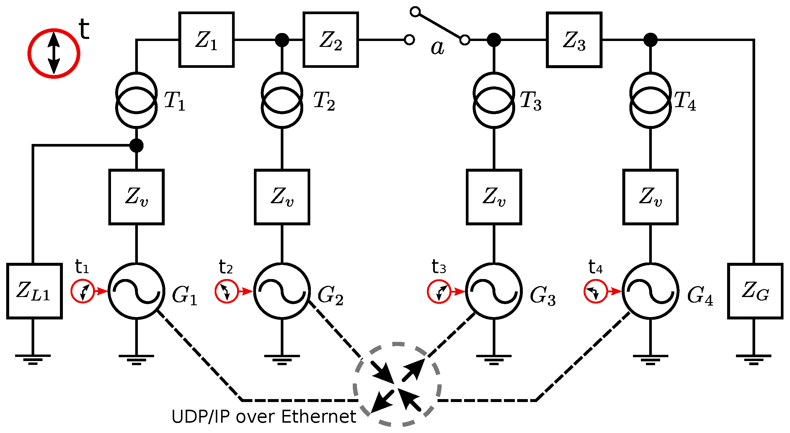
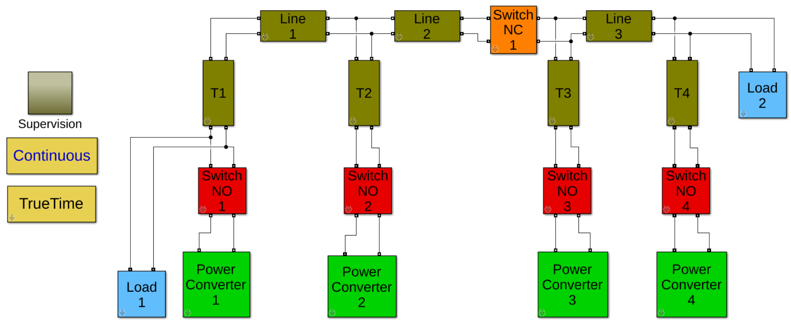
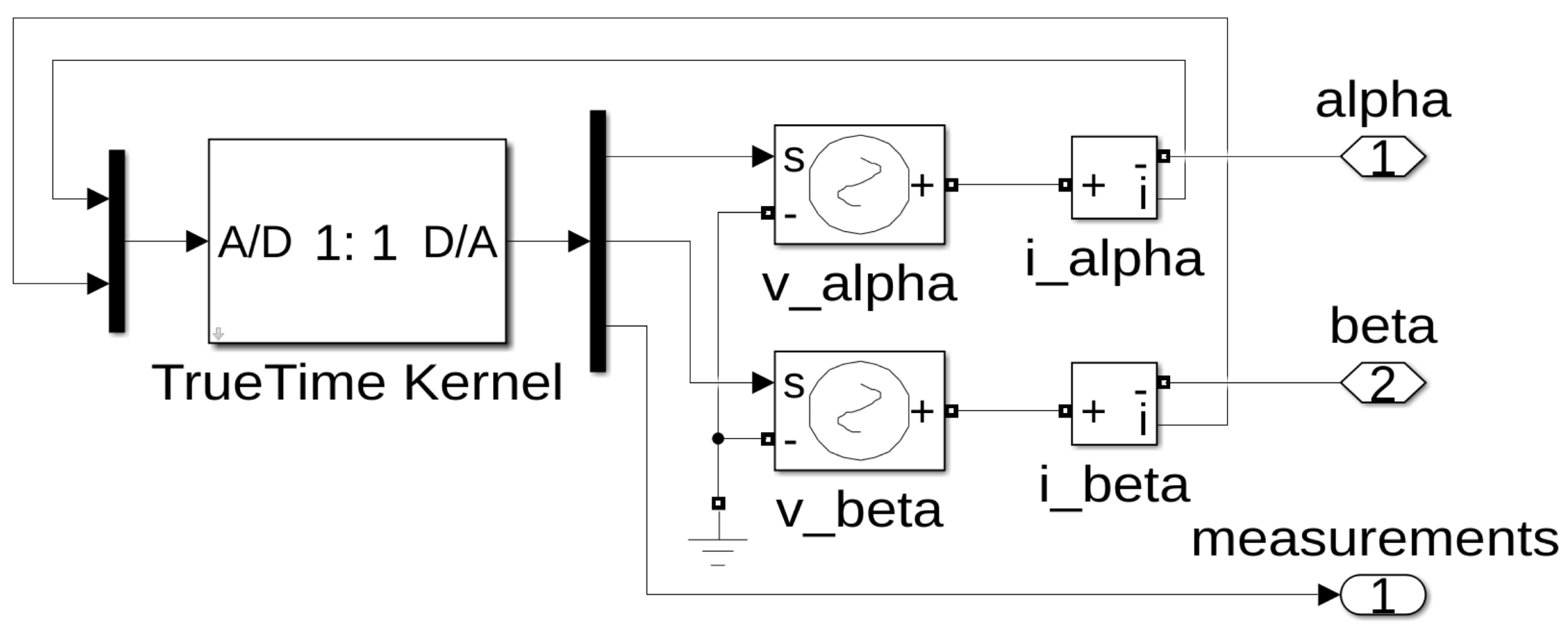
2.1. Communications Network

A simple graph defined as G C = ( N , E C ) models the topology of the MG communications network. N denotes the set of n nodes where each node is a communication terminal belonging to a VSI, E C N × N represents the set of edges, that is, the communication connections among nodes.
Looking at the communications network G C , its Laplacian matrix L R n × n is a symmetric positive semi-definite matrix that represents the physical connections among nodes. It is modeled by
L = j = 1 j 1 n a 1 j a 12 a 1 n a 21 j = 1 j 2 n a 2 j a 2 n a n 1 a n 2 j = 1 j n n a n j ,
where the communication weights a i j are chosen in such a way that L remains balanced. The default setting a i j = 1 indicates unweighted communication between nodes i and j.

2.2. Power Grid

The electrical network includes the same set of n nodes, N , considered in the communications network and a set of edges, E E , representing the electrical connections among nodes. Then, another simple graph defined as G E = ( N , E E ) models the structure of the MG electrical network. The edges E E represent line admittances y i j between each pair of nodes ( i , j ) as in
y i j = g i j + j b i j ,
where g i j R + is the conductance and b i j R + is the susceptance.
A simple model to describe the active power p i ( t ) injected by each i th node in the power grid is expressed as
p i ( t ) = v 2 j 1 n g i j + v 2 j = 1 n b i j ( θ i ( t ) θ j ( t ) ) .
Amplitude v i ( t ) and phase θ i ( t ) both characterize the voltage on each i th node. However, in (3), all nodes’ phase angles and voltages are similar, as usually assumed in power systems modeling [36].
Let us consider the set of VSI active powers as P ( t ) = p 1 ( t ) p n ( t ) T , and the set of phase angles Θ ( t ) = θ 1 ( t ) θ n ( t ) T . The active power in (3) can be developed for all n nodes resulting in a compact form as
P ( t ) = v 2 G 1 n × 1 + v 2 B Θ ( t ) ,
where the matrix G R n × n is formed by the line conductances whose entries are G i j = g i j . The matrix B R n × n is the Laplacian of the power system given by
B = j = 1 j 1 n b 1 j b 12 b 1 n b 21 j = 1 j 2 n b 2 j b 2 n b n 1 b n 2 j = 1 j n n b n j .
Finally, the evolution over time of the power P ( t ) in (4) is given by
P ˙ ( t ) = v 2 B Ω ( t ) ,
where the VSI local frequencies Ω ( t ) are obtained from the derivative of the local phases Θ ( t ) .

3. From Droop to Droop-Free Control

Droop-free control directly ensures frequency regulation and power sharing without relying on the droop method [22]. However, this section demonstrates that droop-free is a distributed droop, spread through communications.
The conventional frequency droop method [4] locally implemented at each node is expressed as
ω i ( t ) = ω 0 m p i ( t ) ,
where ω i ( t ) is the inverter’s voltage frequency, ω 0 is the reference frequency, p i ( t ) is the output active power of the inverter, and m > 0 is the droop proportional control gain. This gain is specified as a trade-off between transient response and stability. Each node i N is modeled as a control law/algorithm implemented at each i th VSI.
By denoting the set of VSI local frequencies by Ω ( t ) = ω 1 ( t ) ω n ( t ) T and the set of desired frequencies by Ω 0 = ω 01 ω 0 n T , the droop control law at each node in (7) can be compacted as
Ω ( t ) = Ω 0 m P ( t ) .
Even though the control laws at all nodes of the MG are included in (8), they are still local and have no direct relation to each other.

Droop-Free Is Droop with Communications

The compact form of the droop method in (7) can be improved by adding communications, as in
Ω ( t ) = Ω 0 e L P ( t ) ,
where the Laplacian matrix L stated in (1) represents the physical communication connections among VSIs. The droop gain term m in (7) has been conveniently replaced by the droop-free gain term e in (9) to differentiate between them.
The distributed control law presented in (9) corresponds to the compact form of the droop-free method for active power sharing and frequency regulation, established in [22]. Then, droop-free is droop plus communications.

4. Proposed Sliding Mode Control

This section develops the theoretical basis of the control method proposed. It includes delimiting the control problem, the sliding mode control proposal, and its stability analysis.

4.1. Delimiting the Control Problem

(1)
The droop-free method has voltage control [22], but this analysis does not cover it because it departs from the frequency/active power approach presented in this work. Instead, the voltage regulation is always enabled through the conventional droop method [4] locally implemented at each node. It is expressed as
v i ( t ) = v 0 c q i ( t ) ,
where v i ( t ) represents the inverter’s voltage amplitude, v 0 is the nominal voltage amplitude, q i ( t ) is the output reactive power of the inverter, and c is the proportional control gain.
(2)
The active power provided by the inverters in steady state p i ( ) must be equal while guaranteeing the supply of the load. It can be expressed as
p i ( ) = p T n ,
where p T is the total power supplied by all inverters.
(3)
The local frequency of each inverter in steady state ω i ( ) can be formulated as
ω i ( ) = ω 0 .
Note that the set-point frequency is the same for all VSIs.

4.2. Sliding Mode Control

Expanding (9) gives
ω i ( t ) = ω 0 + δ i ( t ) ,
δ i ( t ) = m j = 1 n i a i j p j ( t ) n i p i ( t ) ,
where a i j determines the availability of communication between nodes i and j, and n i denotes the number of nodes that exchange control data. Note that at each node i, the powers of the neighboring nodes p j ( t ) are known in addition to the local power p i ( t ) .
The corrective term δ i ( t ) in (13) is replaced by a frequency switching term extracted from the droop-free method, δ i S ( t ) , to formulate the SM control law
ω i ( t ) = ω 0 + δ i S ( t ) .
Then, the switching term δ i S ( t ) is calculated at each i th VSI and operates by following the sign control law
δ i S ( t ) = k i s g n s i ( p ) ,
where the gain k i allows the weight of compensation to be set. The presence of the sign function results in the switching that follows
δ i S ( t ) = k i if s i ( p ) > 0 0 if s i ( p ) = 0 k i if s i ( p ) < 0 .
The frequency switching term in (16) includes a sliding surface s i ( p ) based on the correction term in (14). Therefore, it is a function that calculates the neighborhood active power mismatch for which available communications are required and is defined as
s i ( p ) = j = 1 n i a i j p j ( t ) n i p i ( t ) .
Note that the positive gain m in (14) has been deliberately suppressed because it does not influence the sign of the expression and because the weight of the expression is defined by k i .
By denoting the set of correction terms by Δ S ( t ) = δ 1 S ( t ) δ n S ( t ) T and the set of VSI sliding surfaces by S ( p ) = s 1 ( p ) s n ( p ) T , the SM droop-free control stated in (15)–(18) can be developed for all n nodes resulting in the compact forms
Ω ( t ) = Ω 0 + Δ S ( t ) ,
Δ S ( t ) = k s g n S ( p ) ,
S ( p ) = L P ( t ) .

4.3. Stability Analysis

The quadratic Lyapunov function V ( S ) that considers the sliding surface S ( p ) in (21) is
V ( S ) = 1 2 S ( p ) T S ( p ) = 1 2 ( L P ( t ) ) T L P ( t ) .
Moreover, the candidate function in (22) must satisfy the Lyapunov stability criteria
V ˙ ( S ) = S ( p ) T S ˙ ( p ) < 0 = ( L P ( t ) ) T L P ˙ ( t ) < 0 .
By placing (6) and (19)–(21) into (23), the Lyapunov stability criterion becomes
V ˙ ( S ) = v 2 k ( L P ( t ) ) T L B s g n L P ( t ) < 0 .
In (24), the scalars v and k satisfy v 2 k > 0 . Moreover, both Laplacian matrices L and B are symmetric PSD (positive semidefinite) and their product is also symmetric; therefore, it can be stated that L B 0 . Finally, the factor s i g n ( L P ( t ) ) inherits the negative sign throughout the function. Hence, considering that this inequality holds, the sliding mode controller proposed in (19)–(21) causes the system to be asymptotically stable.
The quadratic Lyapunov function in (22) has helped prove the stability of the linear time-invariant system. However, the dynamic system in (6) could be reframed to design adaptive controllers under the model reference adaptive control framework [37,38]. In this case, a nonquadratic Lyapunov function provides a more flexible and robust control strategy that leads to better tracking accuracy and stability and faster response, even in the presence of uncertainties [38]. However, the choice of a Lyapunov function and the design of the adaptive law can be more complex than quadratic Lyapunov functions.

5. Results

This section presents a simulation set considering a four-node islanded MG to illustrate the introduced control strategy and its performance regarding clock drifts and network partitions.

5.1. Simulation Setup

Figure 1 shows the MG scheme where four DG units of electronically coupled generators G 1 , 2 , 3 , 4 work as VSIs. Each generator independently regulates the amplitude and frequency of the electric supply while providing active and reactive power to feed the shared load Z G ; the local load Z L 1 is supplied by G 1 . Impedances Z 1 , 2 , 3 model parasitic elements in transmission lines while T 1 , 2 , 3 , 4 represent isolation transformers at the output of each power converter. Z v represents the virtual impedance implemented digitally at each power converter. In addition, the MG uses the User Datagram Protocol (UDP) over a switched Ethernet to allow communication among the four inverters. The global time is represented by t, while the local times t 1 , 2 , 3 , 4 illustrate the effect of clock drifts on each VSI.
Matlab and Simulink tools simulate the MG components under the platform presented in [39]. As for the power electricity, SimPowerSystems provides useful component libraries and analysis tools. As for the network, TrueTime is a tool to simulate both real-time controllers and network transmissions. The setup for the simulation in Figure 2 follows the MG scheme in Figure 1.
Generators G 1 to G 4 are simulated by the virtual grid-forming power converters 1 to 4 (green), and the NO switches 1 to 4 (red) to perform the connection/disconnection of the converters to the grid. Loads 1 and 2 (light blue) represent Z L 1 and Z G , lines 1 to 3 (olive) correspond to the impedances Z 1 to Z 3 , and T 1 to T 4 (olive) share the same name as in the MG scheme. The NC switch 1 (orange) induces an electrical partition, which is not contemplated in this study. The supervision block (olive) sends the instantaneous values of active/reactive powers, frequency, amplitude, and local time to the Matlab workspace. The continuous block (yellow) contains the Simulink Simscape elements settings, while the TrueTime block (olive) contains the network settings.
Each grid-forming power converter in Figure 2 has the structure shown in Figure 3. The TrueTime kernel executes the desired control law, and the voltage sources v_alpha and v_beta generate voltages in the α β stationary reference frame, taking the references s given by the control scheme inside the kernel. The intensities provided by each source are measured through the current sensors i_alpha and i_beta and sent to the kernel. The alpha and beta terminals act as power outputs from the converter to the MG, while the measurement terminal serves as the data output. The TrueTime kernel implements clock drifts, virtual impedances, and communications topology through code. More details on the inner control loops regarding power converters are given in [39].
Table 1 summarizes the most relevant settings for the MG. Clock drifts d 1 , 2 , 3 , 4 are intentionally exaggerated to magnify the results. Gains m i in (7) and k i in (16) are tuned to obtain smooth plots for all the cases. These gains have been deliberately considered to be the same for all VSIs; the results presented next also hold for the case where gains are different.

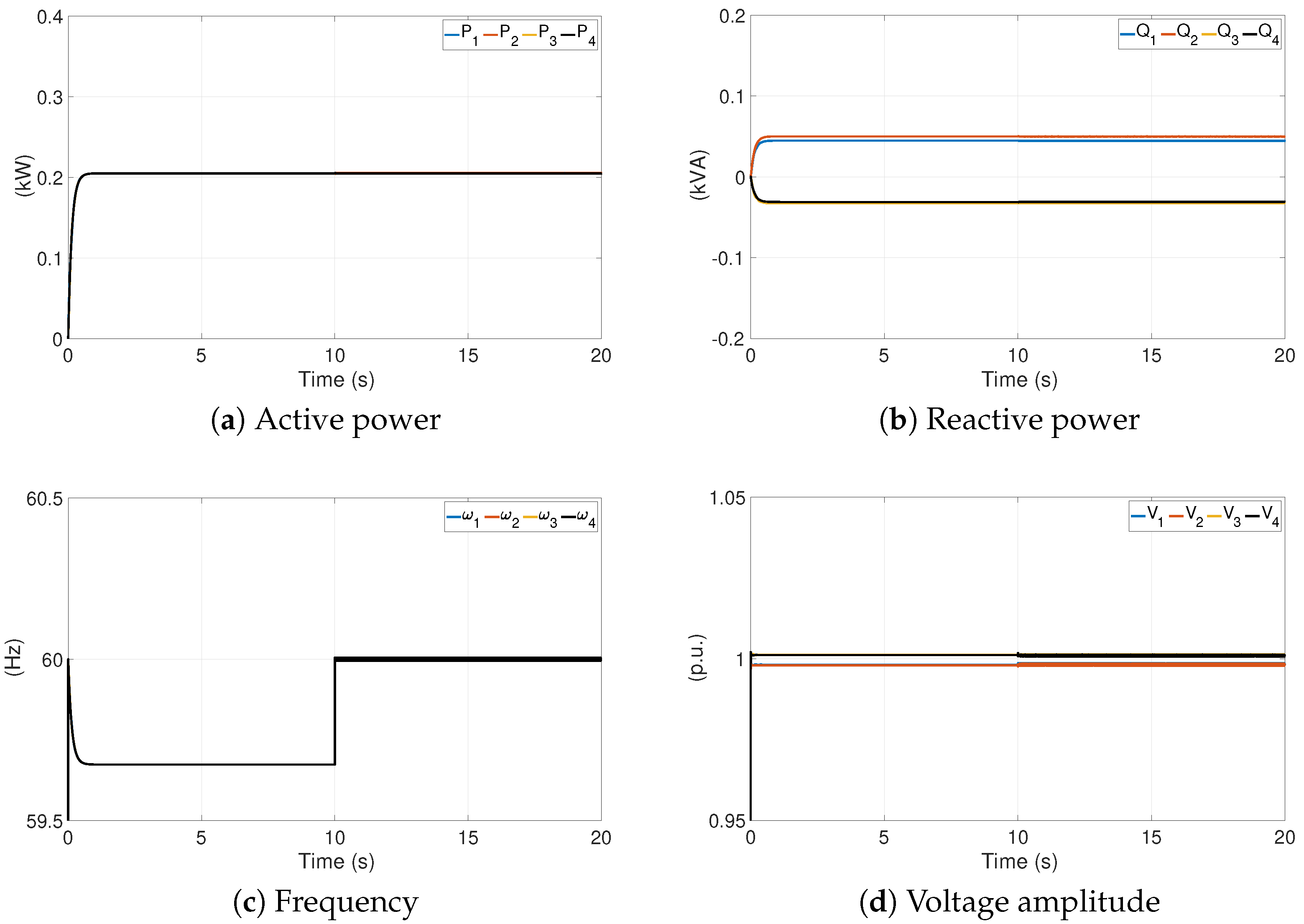
5.2. Simulation Results

Figure 4 shows the MG’s performance before and after implementing the proposed controller to aid in interpreting the results presented. From time t = 0 s, powers evolve controlled by droop under ideal conditions; from t = 10 s, droop-free SM control starts governing. Only the voltage droop method controls the evolution of the reactive power by regulating the voltage amplitude throughout the experiment. When the droop-free SM control governs the system at t = 10 s, the active power remains regulated, now with a short chattering.
Two MG control experiments under the same conditions but with different methods are shown for droop-free sliding mode in Figure 5a,c, and for droop-free in Figure 5b,d. The simulation lasts 20 s and meets the following pattern. From t = 0 s, powers evolve under ideal conditions; from t = 5 s, the clock drifts start to have an effect. In addition, from t = 10 s up to t = 15 s, a load variation appears because Z G decreases and then returns to its original value, thus increasing the power supplied by each VSI. At t = 18 s, a communication failure occurs, i.e., the network topology changes from a unified star to two peer-to-peer connections, G 1 G 2 and G 3 G 4 .
Figure 6 shows both active power and frequency errors as functions of frequency compensation gain k i and transmission rate t r , for 5 s duration simulations.

6. Discussion

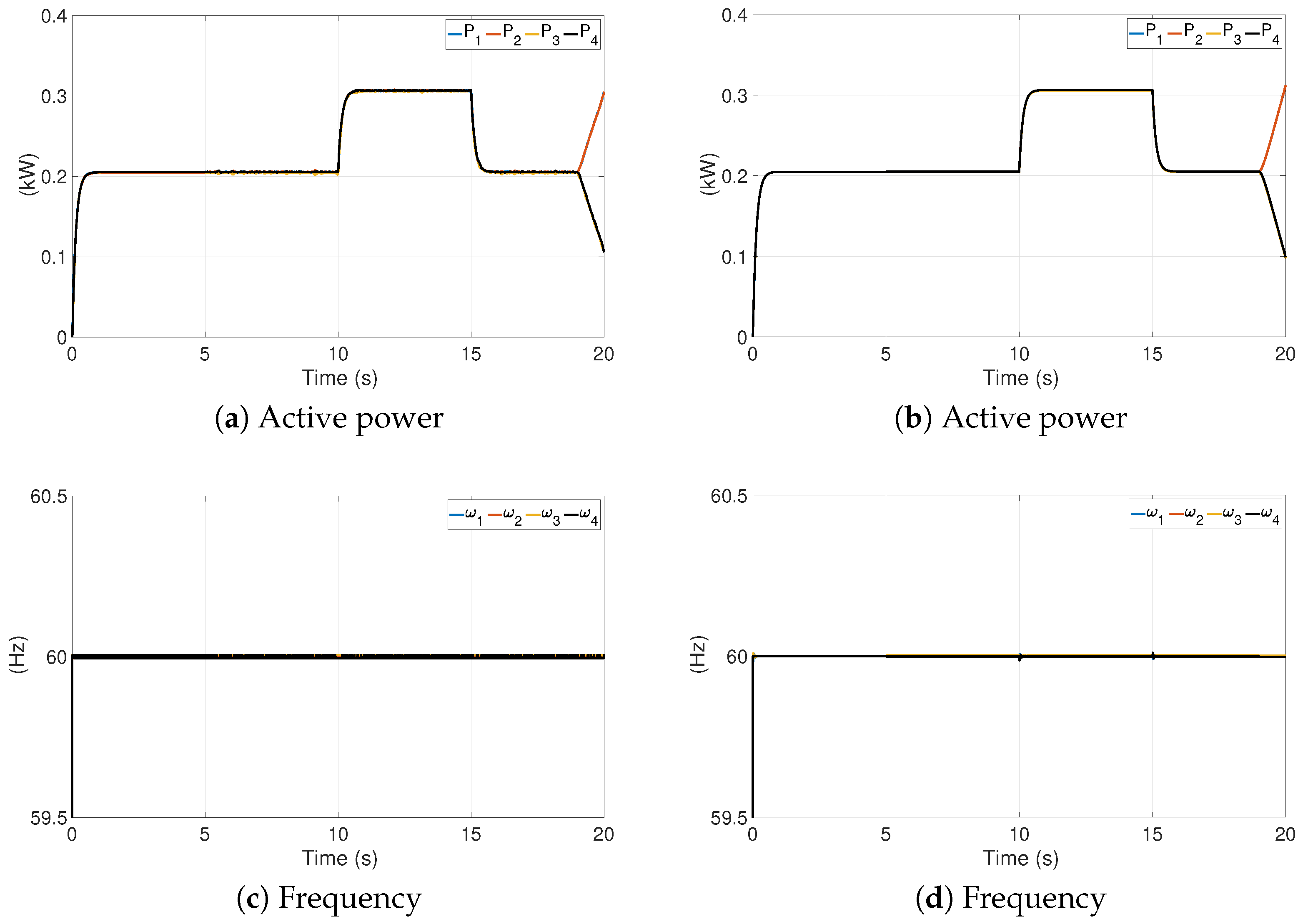
6.1. Active Power Sharing and Frequency Restoration

The most significant contribution of the droop-free SM associated with the droop method in Figure 4 is that frequency restores its dip and holds a slight chattering around the reference. As expected, the voltage amplitude keeps slipping due to the droop control.

6.2. Robustness

After the appearance of the exaggerated clock drifts in Figure 5, the active power exhibits minor deviations while the frequency stays around the nominal value. When a sudden difference in the three-phase balanced global load appears, the total power of the MG goes from 0.8 kW to 1.2 kW and then back to 0.8 kW. At the end, the communication failure causes instability in the MG and drives the powers to diverge on pairs of nodes that are still communicating. Throughout the simulation, a similar dynamic is noted for both droop-free SM and droop-free, except for the chattering in the former, which is a notable feature of this type of control.
The event of a communication partition at t = 18 s, shown in Figure 5, produces two control algorithms working concurrently, one for G 1 G 2 and the other for G 3 G 4 ; despite this, all four generators continue to share the power demand of all loads. The obtained result replicates an effect previously addressed in the literature concerning the droop-free method in [24]. According to this research, the communication partition scenario can be mathematically represented by an integrator introduced into the closed-loop dynamics of the MG. Consequently, any source of uncertainty, e.g., a measurement error or drift, can lead to instability in the dynamics and potentially causes the MG to crash. Moreover, in [40], a control strategy based on operating with local and previously received values ensures precise power distribution when a communication interruption occurs.
In Figure 6, the stability remains despite varying wide ranges of the gain for frequency compensation k i and of the transmission rate for data exchange t r .

6.3. Steady-State Error

The steady-state frequencies ω i ( ) suffer the undesirable phenomenon of chattering. However, their values remain bounded within the tolerance given by the frequency compensation ± k i in the control law (16). This effect is maintained throughout the simulation, despite clock drifts, load changes, and communication failures.
The steady-state powers p i ( ) exhibit slight deviations; nevertheless, the MG shows robust stability even when the change in load appears. This behavior agrees with the results recently obtained in [8] for droop-free control.
The effect of k i gain on active power and frequency errors is shown in Figure 6a–c. The active power error converges to zero, and its oscillation amplitude (due to drifts) increases proportionally to gain; the frequency error remains bounded but increases with k i . On the other hand, the effect of t r on active power and frequency errors is shown in Figure 6b–d. For larger values of t r , the overshoot in the transient response of the active power increases; the frequency error remains bounded as it depends on a fixed k i .

6.4. Comparative Analysis

Table 2 outlines the advantages and disadvantages of the proposed method against the droop-free control.

7. Conclusions and Future Work

This paper has presented a simple droop-free sliding mode control approach for active power sharing and frequency regulation. The study introduces a sliding mode surface dependent on communications that calculates the neighborhood active power mismatch. A stability analysis based on Lyapunov theory, supported by illustrative simulations on a four-node MG, shows the stability robustness of the proposal. The results confirm that frequency restoration is always achieved regardless of disturbances. However, there is frequency chattering that could decrease the performance of electronics on which further studies should be focused. Regarding active power, the results reveal that power sharing is stable. Clock drifts cause minor deviations in power, and the controller tracks load changes. Network communication failures harm power sharing, leading MG to instability; this motivates the development of mechanisms that improve performance against this problem.
In future work, this approach will be extended to implement an additional surface for reactive power sharing and voltage regulation based on droop-free control. We plan to explain the critical behavior in the face of communication failures and to improve robustness against them by adding a surface based on the local dynamics of each VSI. Using the solutions in [24,40] as foundational work to solve this problem will also be contemplated. The effect of chattering will be reduced through the implementation of filtering techniques.

Author Contributions

This paper was a collaborative effort among all authors. All authors participated in the analysis, discussed the results, and wrote the paper. All authors have read and agreed to the published version of the manuscript.

Funding

This research was funded by the University Center for Scientific and Technological Research (CUICYT), belonging to Universidad Técnica del Norte, grant number 1086.

Conflicts of Interest

The authors declare no conflict of interest.

References

  1. Buso, S.; Caldognetto, T. Rapid prototyping of digital controllers for microgrid inverters. IEEE J. Emerg. Sel. Top. Power Electron. 2014, 3, 440–450. [Google Scholar] [CrossRef]
  2. Guerrero, J.M.; Vasquez, J.C.; Matas, J.; De Vicuña, L.G.; Castilla, M. Hierarchical control of droop-controlled AC and DC microgrids: A general approach toward standardization. IEEE Trans. Ind. Electron. 2011, 58, 158–172. [Google Scholar] [CrossRef]
  3. Olivares, D.E.; Mehrizi-Sani, A.; Etemadi, A.H.; Cañizares, C.A.; Iravani, R.; Kazerani, M.; Hajimiragha, A.H.; Gomis-Bellmunt, O.; Saeedifard, M.; Palma-Behnke, R.; et al. Trends in microgrid control. IEEE Trans. Smart Grid 2014, 5, 1905–1919. [Google Scholar] [CrossRef]
  4. Chandorkar, M.C.; Divan, D.M.; Adapa, R. Control of parallel connected inverters in standalone AC supply systems. IEEE Trans. Ind. Appl. 1993, 29, 136–143. [Google Scholar] [CrossRef]
  5. Schiffer, J.; Ortega, R.; Astolfi, A.; Raisch, J.; Sezi, T. Conditions for stability of droop-controlled inverter-based microgrids. Automatica 2014, 50, 2457–2469. [Google Scholar] [CrossRef]
  6. Andreasson, M.; Dimarogonas, D.V.; Sandberg, H.; Johansson, K.H. Distributed control of networked dynamical systems: Static feedback, integral action and consensus. IEEE Trans. Autom. Control 2014, 59, 1750–1764. [Google Scholar]
  7. Han, Y.; Li, H.; Shen, P.; Coelho, E.A.A.; Guerrero, J.M. Review of active and reactive power sharing strategies in hierarchical controlled microgrids. IEEE Trans. Power Electron. 2017, 32, 2427–2451. [Google Scholar] [CrossRef]
  8. Martí, P.; Torres-Martínez, J.; Rosero, C.X.; Velasco, M.; Miret, J.; Castilla, M. Analysis of the effect of clock drifts on frequency regulation and power sharing in inverter-based islanded microgrids. IEEE Trans. Power Electron. 2018, 33, 10363–10379. [Google Scholar] [CrossRef]
  9. Wen, S.; Yu, X.; Zeng, Z.; Wang, J. Event-triggering load frequency control for multiarea power systems with communication delays. Trans. Ind. Electron. 2016, 63, 1308–1317. [Google Scholar] [CrossRef]
  10. Li, C.; Yu, X.; Yu, W.; Huang, T.; Liu, Z.W. Distributed event-triggered scheme for economic dispatch in smart grids. IEEE Trans. Ind. Informat. 2016, 12, 1775–1785. [Google Scholar] [CrossRef]
  11. Dong, L.; Tang, Y.; He, H.; Sun, C. An event-triggered approach for load frequency control with supplementary ADP. IEEE Trans. Power Syst. 2017, 32, 581–589. [Google Scholar] [CrossRef]
  12. Dou, C.; Yue, D.; Guerrero, J.M. Multiagent system-based event-triggered hybrid controls for high-security hybrid energy generation systems. IEEE Trans. Ind. Informa. 2017, 13, 584–594. [Google Scholar]
  13. Zhou, J.; Zhang, H.; Sun, Q.; Ma, D.; Huang, B. Event-based distributed active power sharing control for interconnected AC and DC microgrids. IEEE Trans. Smart Grid 2018, 9, 6815–6828. [Google Scholar] [CrossRef]
  14. Mohamed, Y.A.I.; El-Saadany, E.F. Adaptive decentralized droop controller to preserve power sharing stability of paralleled inverters in distributed generation microgrids. IEEE Trans. Power Electron. 2008, 23, 2806–2816. [Google Scholar] [CrossRef]
  15. Hua, M.; Hu, H.; Xing, Y.; Guerrero, J.M. Multilayer control for inverters in parallel operation without intercommunications. IEEE Trans. Power Electron. 2012, 27, 3651–3663. [Google Scholar] [CrossRef]
  16. Rey, J.M.; Martí, P.; Velasco, M.; Miret, J.; Castilla, M. Secondary switched control with no communications for islanded microgrids. IEEE Trans. Ind. Electron. 2017, 64, 8534–8545. [Google Scholar]
  17. Rey, J.M.; Rosero, C.X.; Velasco, M.; Marti, P.; Miret, J.; Castilla, M. Local frequency restoration for droop-controlled parallel inverters in islanded microgrids. IEEE Trans. Energy Convers. 2019, 34, 1232–1241. [Google Scholar] [CrossRef]
  18. Palizban, O.; Kauhaniemi, K. Secondary control in AC microgrids: Challenges and solutions. In Proceedings of the 2015 International Conference on Smart Cities and Green ICT Systems (SMARTGREENS), Lisbon, Portugal, 20–22 May 2015. [Google Scholar]
  19. Simpson-Porco, J.W.; Shafiee, Q.; Dorfler, F.; Vasquez, J.C.; Guerrero, J.M.; Bullo, F. Secondary frequency and voltage control of islanded microgrids via distributed averaging. IEEE Trans. Ind. Electron. 2015, 62, 7025–7038. [Google Scholar]
  20. Huang, P.H.; Liu, P.C.; Xiao, W.; El Moursi, M.S. A novel droop-based average voltage sharing control strategy for DC microgrids. IEEE Trans. Smart Grid 2015, 6, 1096–1106. [Google Scholar] [CrossRef]
  21. Guo, F.; Wen, C.; Mao, J.; Song, Y.D. Distributed secondary voltage and frequency restoration control of droop-controlled inverter-based microgrids. IEEE Trans. Ind. Electron. 2015, 62, 4355–4364. [Google Scholar] [CrossRef]
  22. Nasirian, V.; Shafiee, Q.; Guerrero, J.M.; Lewis, F.L.; Davoudi, A. Droop-free distributed control for AC microgrids. IEEE Trans. Power Electron. 2016, 31, 1600–1617. [Google Scholar] [CrossRef]
  23. Dörfler, F.; Simpson-Porco, J.W.; Bullo, F. Breaking the hierarchy: Distributed control and economic optimality in microgrids. IEEE Trans. Control Netw. Syst. 2016, 3, 241–253. [Google Scholar] [CrossRef]
  24. Rosero, C.X.; Velasco, M.; Martí, P.; Camacho, A.; Miret, J.; Castilla, M. Active power sharing and frequency regulation in droop-free control for islanded microgrids under electrical and communication failures. IEEE Trans. Ind. Electron. 2020, 67, 6461–6472. [Google Scholar] [CrossRef]
  25. Schiffer, J.; Hans, C.A.; Kral, T.; Ortega, R.; Raisch, J. Modeling, analysis, and experimental validation of clock drift effects in low-inertia power systems. IEEE Trans. Ind. Electron. 2017, 64, 5942–5951. [Google Scholar] [CrossRef]
  26. Cucuzzella, M.; Incremona, G.P.; Ferrara, A. Design of robust higher order sliding mode control for microgrids. IEEE J. Emerg. Sel. Top. Circuits Syst. 2015, 5, 393–401. [Google Scholar] [CrossRef]
  27. Rubagotti, M.; Estrada, A.; Castanos, F.; Ferrara, A.; Fridman, L. Integral sliding mode control for nonlinear systems with matched and unmatched perturbations. IEEE Trans. Automat. 2011, 56, 2699–2704. [Google Scholar] [CrossRef]
  28. Utkin, V. Variable structure Systems with sliding modes. IEEE Trans. Automat. 1977, 22, 212–222. [Google Scholar] [CrossRef]
  29. Abdollahi, M.H.; Bathaee, S.M. Sliding mode controller for stability enhancement of microgrids. In Proceedings of the IEEE/PES Transmission and Distribution Conference and Exposition, Chicago, IL, USA, 21–24 April 2008; pp. 1–6. [Google Scholar]
  30. Pilloni, A.; Pisano, A.; Usai, E. Robust finite-time frequency and voltage restoration of inverter-based microgrids via sliding-mode cooperative control. IEEE Trans. Power Electron. 2018, 65, 907–917. [Google Scholar]
  31. Sarrafan, N.; Rostami, M.A.; Zarei, J.; Razavi-Far, R.; Saif, M.; Dragicevic, T. Improved distributed prescribed finite-time secondary control of inverter-based microgrids: Design and real-time implementation. IEEE Trans. Ind. Electron. 2020, 68, 11135–11145. [Google Scholar]
  32. Alfaro, C.; Guzman, R.; De Vicuña, L.G.; Komurcugil, H.; Martín, H. Distributed direct power sliding-mode control for islanded AC microgrids. IEEE Trans. Ind. Electron. 2022, 69, 9700–9710. [Google Scholar] [CrossRef]
  33. Incremona, G.P.; Cucuzzella, M.; Ferrara, A. Adaptive suboptimal second-order sliding mode control for microgrids. Int. J. Control 2016, 89, 1849–1867. [Google Scholar]
  34. Morstyn, T.; Savkin, A.V.; Hredzak, B.; Agelidis, V.G. Multi-agent sliding mode control for state of charge balancing between battery energy storage systems distributed in a DC microgrid. IEEE Trans. Smart Grid 2017, 9, 4735–4743. [Google Scholar]
  35. Veysi, M.; Aghaei, J.; Soltanpour, M.R.; Shasadeghi, M.; Bahrani, B.; Ryan, D.J. Robust, accurate, and fast decentralized power sharing mechanism for isolated DC microgrid using droop-based sliding-mode control. IEEE Trans. Smart Grid 2022, 13, 4160–4173. [Google Scholar]
  36. Kundur, P.S.; Malik, O.P. Power System Stability and Control; McGraw-Hill Education: New York, NY, USA, 2022. [Google Scholar]
  37. Tao, G. Model reference adaptive control with L1+α tracking. Int. J. Control 1996, 64, 859–870. [Google Scholar]
  38. Hosseinzadeh, M.; Yazdanpanah, M.J. Performance enhanced model reference adaptive control through switching non-quadratic Lyapunov functions. Syst. Control Lett. 2015, 76, 47–55. [Google Scholar]
  39. Rosero, C.X.; Vaca, C.; Gavilanez, M.; Iglesias, I.; Rosero, R. Towards a simulation platform for islanded microgrids based on grid-forming power converters. In Proceedings of the IEEE 5th Colombian Conference on Automatic Control (CCAC), Virtualy, Ibague, Colombia, 19–22 October 2021; pp. 1–6. [Google Scholar]
  40. Mohammed, N.; Lashab, A.; Ciobotaru, M.; Guerrero, J.M. Accurate Reactive Power Sharing Strategy for Droop-Based Islanded AC Microgrids. IEEE Trans. Ind. Electron. 2023, 70, 2696–2707. [Google Scholar]
Figure 1. Microgrid setup.
Energies 16 06442 g001
Figure 2. Scheme for the simulated MG.
Energies 16 06442 g002
Figure 3. Virtual grid-forming power converter.
Energies 16 06442 g003
Figure 4. Frequency droop control from t = 0 s followed by droop-free sliding mode control from t = 10 s govern (a) active power sharing and (c) frequency regulation, while voltage droop control from t = 0 s and along the experiment controls (b) reactive power sharing and (d) voltage regulation.
Energies 16 06442 g004
Figure 5. Active power sharing and frequency regulation governed by droop-free SM control (a,c), and by droop-free control (b,d), under clock drifts from t = 5 s, load change t = 10 –15 s, and communication failure from t = 18 s.
Energies 16 06442 g005
Figure 6. Active power error (a) and frequency error (c), both versus frequency compensation gain k i , as well as active power error (b) and frequency error (d), both versus transmission rate t r , when droop-free sliding mode control governs the islanded MG.
Energies 16 06442 g006
Table 1. Microgrid setup parameters.
SymbolDescriptionValue
v 0 Grid voltage (rms line to line) 3 110 V
ω 0 Grid frequency (at no load) 2 π 60 rad/s
Z 1 Transmission line impedance1.3 m Ω @ 36 . 9
Z 2 , 3 Transmission line impedances 2 and 31 m Ω @ 16 . 7
T 1 , 2 Transformer impedances 1 and 20.62 m Ω @ 37 . 01
T 3 , 4 Transformer impedances 3 and 41.31 m Ω @ 9 . 87
Z G maxMaximum global load impedance88 Ω @ 0
Z G minMinimum global load impedance44 Ω @ 0
Z L 1 Local load impedance 188 Ω @ 0
Z v Virtual impedance3.76 m Ω @ 90
c 1 , 2 , 3 , 4 Gains for voltage droop1 μ V/(VAr)
m 1 , 2 , 3 , 4 Gains for frequency droop1 mrad/(Ws)
k 1 , 2 , 3 , 4 Gains for frequency compensation in sliding mode 2 π 5 mrad/(Ws)
e 1 , 2 , 3 , 4 Gains for droop-free10 mrad/(Ws)
d 1 Clock drift rate in G 1 1.0000 ppm
d 2 Clock drift rate in G 2 1.00001 ppm
d 3 Clock drift rate in G 3 0.9999 ppm
d 4 Clock drift rate in G 4 1.00002 ppm
t s Sampling period 0.1 ms
t r Data transmission period 0.1 ms
Table 2. Comparative analysis between droop-free SM control and droop-free control.
Control MethodAdvantagesDisadvantages
Droop-free SMMinimal active power steady-state errorFrequency chattering
Robust to clock drifts and load changesUnstable in communication partitions
Easy to implement
Opportunity to be improved through filtering techniques for chattering and additional sliding surface for reactive power sharing
Droop-freeRobust to clock drifts and load changesUnstable in communication partitions
Minimal steady-state errors for active power and frequency
Disclaimer/Publisher’s Note: The statements, opinions and data contained in all publications are solely those of the individual author(s) and contributor(s) and not of MDPI and/or the editor(s). MDPI and/or the editor(s) disclaim responsibility for any injury to people or property resulting from any ideas, methods, instructions or products referred to in the content.

