Article

High-Temperature Heat Pump Using CO2-Based Mixture for Simultaneous Heat and Cold Energy Reservation

1
School of Transportation and Vehicle Engineering, Shandong University of Technology, Zibo 255000, China
2
School of Mechanical Engineering, Beijing Institute of Technology, Beijing 100083, China
3
Hisense Group Holding Co., Ltd., Qingdao 266100, China
4
Shandong Qihao New Energy Technology Co., Ltd., Zibo 255400, China
*
Authors to whom correspondence should be addressed.
These authors contributed equally to this work.
Energies 2023, 16(18), 6587; https://doi.org/10.3390/en16186587
Submission received: 12 August 2023 / Revised: 2 September 2023 / Accepted: 10 September 2023 / Published: 13 September 2023
(This article belongs to the Special Issue Low-Carbon Energy System Management Towards Sustainable Cities)

Abstract

:
To leverage temperature glide in evaporation, a transcritcal heat pump using a CO2-based mixture is investigated from a perspective of simultaneous heat and cold energy storage. Coefficient of performance for heating (COPh) and exergy efficiency are used to evaluate system performance. A parametric investigation on the heat pump is conducted, and the coupling behavior of the cycle with thermal energy storage (TES) material is investigated in view of stored exergy of TES. Optimization and comparative studies are carried out among various mixtures. The results reveal that maximum cycle temperature is mainly affected by high pressure and superheating degree, while minimum cycle temperature, as well as cold exergy, is highly dependent on evaporating temperature glide, with little influence from high pressure. The total exergy efficiency can reach up to 60%. The temperature of low temperature TES could reach as low as −32.4 °C for CO2/R601, providing the largest proportion of cold exergy to total exergy, up to 30.1%.

1. Introduction

The technology for large-scale utilization of renewable energy brings bright solutions for the development of modern society. However, it is well known that the massive integration of intermittent renewable energy production generates new challenges for the supervision and regulation of electric grids [1]. Load is traditionally employed to balance demand and supply of electric grids, but it is energy- and carbon-intensive. Therefore, large-scale electricity storage with a much lower environmental impact is a promising alternative to ensure the maintenance of grid frequency and power quality. The established technologies for bulk energy storage are pumped hydro storage (PHS) and compressed air energy storage (CAES), both of which rely on geological conditions, and are hence constrained in their deployment [2,3].
TES is another choice for smoothing the peaks of electric energy, in view of its flexible scale from small to large capacity based on its usage. Depending on TES temperature, this energy storage system could be used for sole electricity, heat production, or cogeneration. Research on improving the thermal efficiency of storage units has been conducted, from a view point of fin structure modification or enhanced PCM [4,5]. Based on the energy-saving-technology heat pump, the concept of Pumped Thermal Electricity Storage (PTES) [6,7], or the Carnot battery [8,9], has been presented. The basic idea is to convert electric energy into heat through a heat pump, then charge a TES, and finally convert the heat back with heat engines. Furthermore, a new large-capacity energy storage device based on a hybrid cycle of a CO2 heat pump cycle and a CO2 hydrate heat cycle was presented in [10]. It is obvious that heat pumps play a vital role in TES systems.
Heat pump systems inherently offer unique advantages in terms of energy usage, with a coefficient of performance greater than one [11]. Nowadays, green and high-efficiency are the core themes of heat pump development. In response to the Montreal Protocol and the Kigali Amendment, natural refrigerants, such as CO2, came back into people’s sight. The characteristics and performance of the CO2 heat pump are different from those of heat pumps in subcritical operations due to the different cycle and pinch point effects. CO2 transcritical heat pump cycle, a near-triangle cycle with a large temperature glide and near-linear temperature change during the isobaric process in the supercritical region, is beneficial and widely used for water or gas heating with a large temperature glide [12]. The prevailing view is that the CO2 heat pump is more efficiently used for direct water heating due to the lower inlet water temperature [13]. A CO2 heat pump is used to recover waste heat from the data center; generated heat is stored in the soil in the non-heating period [14], and the prosumer system facilitates flexible and effective utilization by introduction of heat pump. The COPs of CO2 heat pump vary from 3.12 to 2.46, with high temperature water ranging from 65 to 120 °C [15].
Recently, the study of CO2-based mixtures as refrigerants has become prevalent, with the aim of increasing the COP and heating capacity or improving refrigerants’ environmental properties. Sun et al. [16] investigated CO2/R32 blends for the heat pump water heater; their results indicate that a maximum 23.3% improvement of COP is obtained. Compared to pure CO2 cycles, CO2/R41 and CO2/R32 exhibit higher COP and lower high-side pressure [17]. Zeotropic CO2-based refrigerant mixtures were considered for cascade high-temperature heat pumps to deliver hot water at a temperature above 115 °C; the maximum heat sink temperature was 181.6 °C and 118.9 °C when using the 20% and 5% CO2, respectively, in the refrigerant mixture [18]. The use of a new zeotropic mixture composed of CO2 and acetone as the refrigerant of a high temperature heat pump working in the temperature range of 150–220 °C was proposed in [19]; an optimal COP of 5.63 is obtained under temperature lift of 70 K.
Due to the temperature glide in evaporation, a transcritical heat pump using a CO2-based mixture serves more like the Lorenz cycle, which could achieve higher heat pump performance. Specifically, the changing temperature of the refrigerant better matches the temperature profile of the heat source to achieve performance improvement. Based on temperature glide matching, the irreversibility of the heat transfer is reduced [20], and performance increase of the simple heat pump cycle reaches up to 20% [21]. On the other hand, by taking advantage of the thermal glide of the CO2-based mixture, a lower temperature of the refrigerant leaving the throttle valve would be obtained, creating the conditions for cold generation. However, previous researches mainly focused on the heating performance of heat pumps, and the generated cold energy has not attracted enough attention. Hence, the simultaneous heat and cold energy utilization of heat pumps using a zeotropic mixture is worth investigating.
The purpose of the present work is to evaluate the thermodynamic performance of a transcritical heat pump using a CO2-based mixture for simultaneous heat and cold energy storage. According to investigations from three aspects—a cycle parametric investigation, coupling behavior of the cycle with TES material, and a comparative study on mixtures—this paper may provide a comprehensive assessment of a heat pump for combined cold and heat generation. The novelty of this work is to extend the performance judgment of the heat pump to comprehensive heat and cold utilization, by virtue of evaporating temperature glide. A second novelty perhaps lies in the proposed internal recuperation with two-phase latent energy utilization, which could reduce minimum cycle temperature without additional work.

2. Methodology

2.1. System Description

The schematic diagram of the heat pump system for energy storage is illustrated in Figure 1. In order to obtain heat and cold energy at the same time, the working fluid needs proper glide temperature during evaporation; therefore, a transcritical vapor compression heat pump (VCHP) cycle using CO2-based binary mixtures is considered in this work. An internal regenerator is introduced to the VCHP system, in order to achieve lower temperature before and after throttling. The system has two TESs. The high temperature (HT) TES couples with a gas cooler and receives heat during VCHP operation. The low temperature (LT) TES couples with an evaporator and rejects heat to the VCHP to achieve a state below environmental temperature. In view of the working fluid’s variable temperature in the heat rejection/injection process, both high- and low-temperature heat storage adopt the two-tank liquid sensible TES solution for simplicity. For sensible TES systems, heat is stored or rejected by modulating the temperature of the storage material, typically within a single phase [9]. Pressurized water is often considered as high-temperature liquid sensible heat storage, in view of its advantages of high thermal capacity, along with being cheaply available and environmentally friendly [1]. As for low-temperature TES, a water solution with ethylene glycol is commonly used, since its operating temperatures can reach −30 °C [22].
For the HT-TES system, pressurized water at atmospheric temperature flows through a gas cooler in the VCHP system and absorbs heat to raise the temperature. Once heated, high-temperature water is stored in a hot reservoir. During usage, the high-temperature water is pumped out and rejects heat to users through the heat exchanger. Then, the cooled water is temporary stored in a storage tank before the next cyclic utilization. The working principle of the LT-TES system is similar to that of the HT-TES system, and detailed explanation is omitted here.

2.2. Thermodynamic Model

This analysis is based on the first and second laws of thermodynamics. COP and exergy efficiency are considered as metrics to evaluate VCHP system performance. COP represents thermodynamic performance of the heat pump, but it cannot distinguish the quality of generated thermal energy. Therefore, exergy efficiency is introduced to represent the effectiveness of system for energy conversion and storage.
Working fluid pump power consumption can be expressed as:
W ˙ com = m ˙ r h 2 h 1
The compressor isentropic efficiency can be expressed as:
η com = h 2 s h 1 / h 2 h 1
Heat rejection in the condenser can be expressed as:
Q ˙ H =   m ˙ r h 2 h 3 =   m ˙ hs c p ,   hs ( T hs ,   out T hs ,   in )
Heat input in the evaporator can be expressed as:
Q ˙ C = m ˙ r h 5 h 6 =   m ˙ cs c p ,   cs ( T cs ,   in T cs ,   out )
where subscripts ‘hs’ and ‘cs’ represent high- and low-temperature energy storage materials, respectively.
Throttling in the expansion valve can be expressed as:
h 4 = h 5
The expansion valve is considered to be adiabatic, resulting in equal enthalpy before and after throttling.
The energy balance in the internal regenerator is expressed as:
h 3 h 4 = h 1 h 6
For heat energy conversion, COPh is the ratio of the heat delivered to the overall power consumption of the cycle, as follows:
COP h = Q ˙ H W ˙ com
For cold energy storage, COPc indicates the cold energy generated to overall power consumption, as follows:
COP c = Q ˙ C W ˙ com
According to the law of conservation of energy, two merits have the following relationship:
COP c = COP h 1
Exergy indicates the potential to generate power, which can be defined as the maximum work that can be extracted from a thermodynamic system from its current state until a final state of equilibrium with the environment—the dead state—is reached [23]. Flow exergy of the working fluid can be calculated using Equation (10), where h0 and s0 are reference values of environment conditions.
E ˙ flow = m ˙ h h 0 m ˙ T 0 s s 0
Therefore, the flow exergy of sensible TES material exiting the VCHP heat exchanger unit could represent exergy generated, and the heat exergy rate and cold exergy rate could be expressed as follows, respectively:
E ˙ H = m ˙ hs h hs , out h hs , 0 m ˙ hs T 0 s hs , out s hs , 0
E ˙ C = m ˙ cs h cs , out h cs , 0 m ˙ cs T 0 s cs , out s cs , 0
Consequently, a higher temperature for HT-TES, and lower temperature for LT-TES, indicates a lager exergy rate. The total exergy rate in the system is the sum of heat and cold exergy rate:
E ˙ tot = E ˙ H + E ˙ C
The exergy efficiency is defined as the ratio of profit exergy to the cost exergy, which is formulated as follows:
η ex = E ˙ tot W ˙ com

2.3. Assumptions

A MATLAB code is programed for the simulation, combined with REFPROP 10.0 for calculating properties of refrigerants. In order to simplify the calculation, the following typical assumptions are made:
(1)
Each component is considered to be steady-state and steady-flow.
(2)
Pressure losses and heat losses in all heat exchangers and pipelines are neglected.
(3)
Overall composition of the mixture in each component keeps constant.
(4)
Only counter-flow heat exchangers are used in the system.
(5)
The environmental temperature is equal to the inlet temperature of the TES.
(6)
The leakage of working fluid from the components are negligible.
(7)
The evaporating temperature for mixtures refers to dew point temperature.
The simulation conditions used in this study are listed in Table 1. To guarantee the transcritical cycle configuration, the high operation pressure is restricted to no less than 1.1 pcrit. The mass flow rate of the refrigerant is set to be 1 kg/s. The pinch point temperature difference between the refrigerant and the TES is fixed at 5 °C [6,24]. The pinch point location is calculated by an element division and iteration method, as used in our previous work [25]. The approach temperature difference, defined as the difference value between the saturated gas temperature and the evaporator exiting temperature, is used to control the refrigerant’s temperature-matching in IHX. The superheating degree, which varies from 5 °C to 20 °C, is assumed at the compressor inlet, aiming to obtain higher temperature while maintaining a constant pressure ratio. The ambient temperature and pressure at the standard reference states are, respectively, 25 °C and 0.1 MPa. The target temperature for HT-TES is set to be 130 °C [1], while the minimum temperature of LT-TES is passively determined based on operation conditions. The outlet temperature of the refrigerant, as well as the mass flow of TES, is calculated based on heat balance, considering pinch restriction.

3. Results and Discussion

It is necessary to carry out a parametric study and optimization of the heat pump energy storage system, aiming to find out the change rule of thermodynamic performance with key operation parameters. In this section, the influence of main parameters on heat pump cycle performance is conducted first. Subsequently, the coupling relations between cycle and external TESs are investigated. The mixture of CO2/R134a exhibits various temperature glide feature with a change of composition; hence, it is appointed as representative in parametric study. Finally, a comparative study based on maximum reachable efficiencies among different refrigerants is performed.

3.1. Parametric Influence Analysis of Cycle

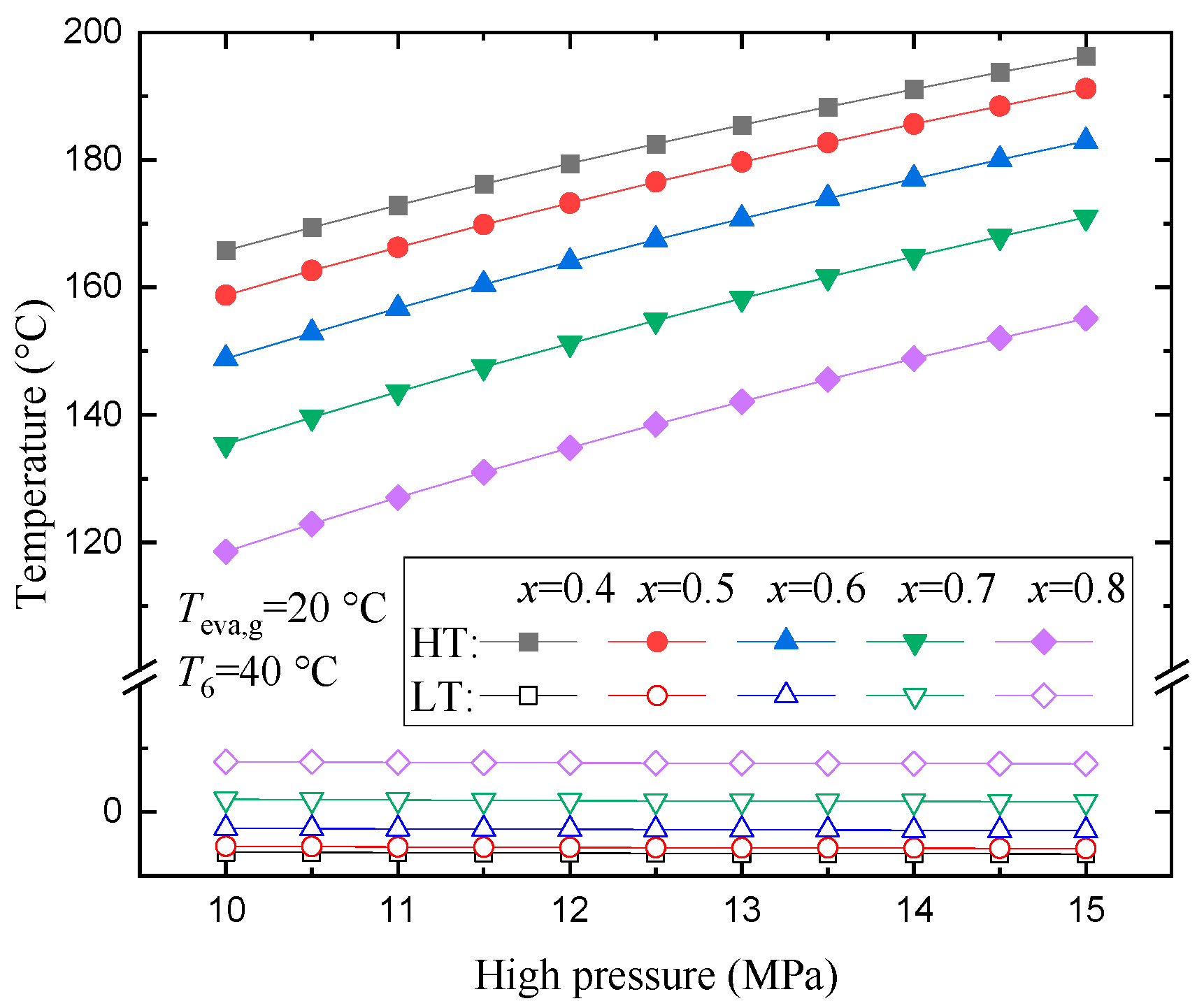
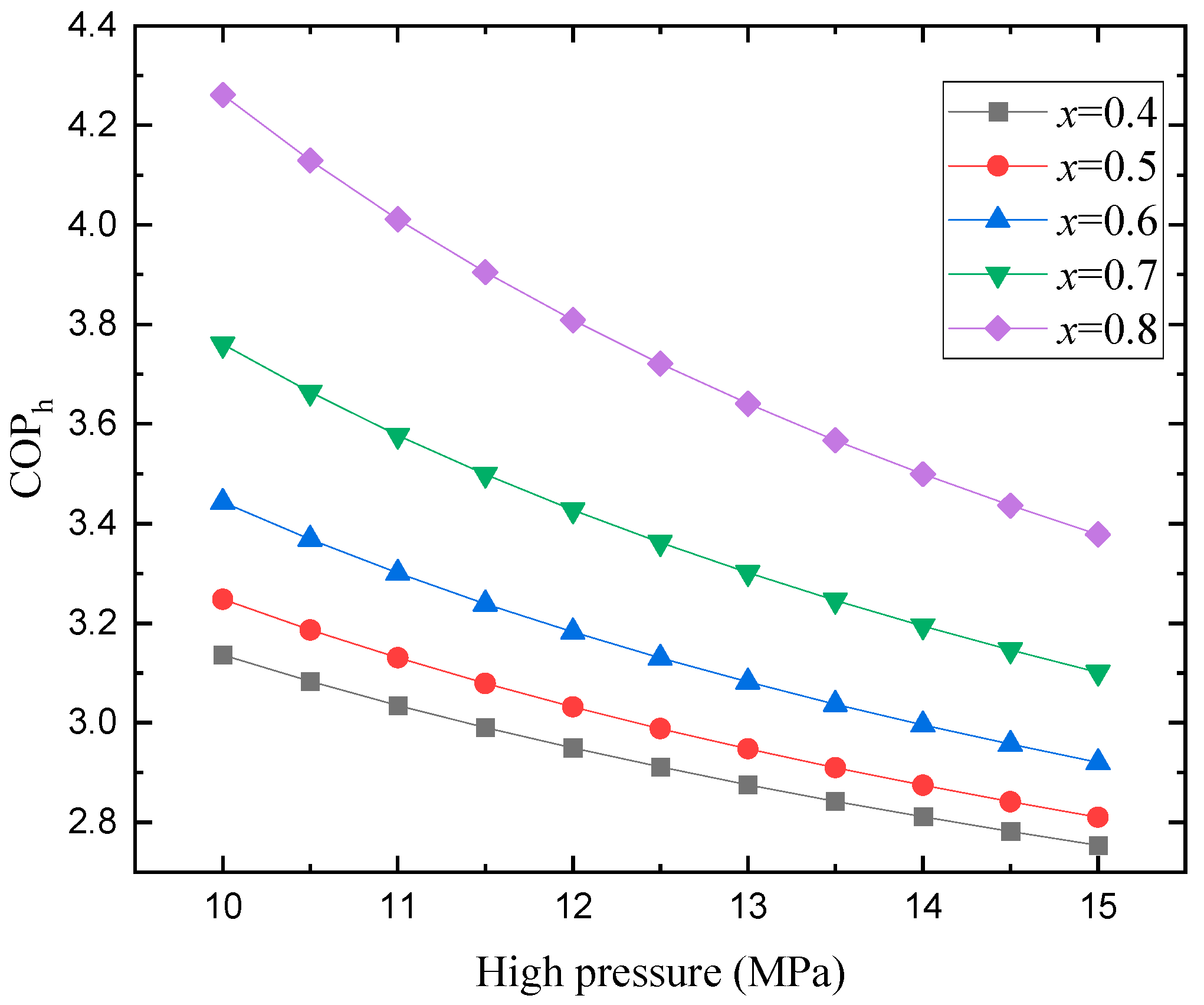
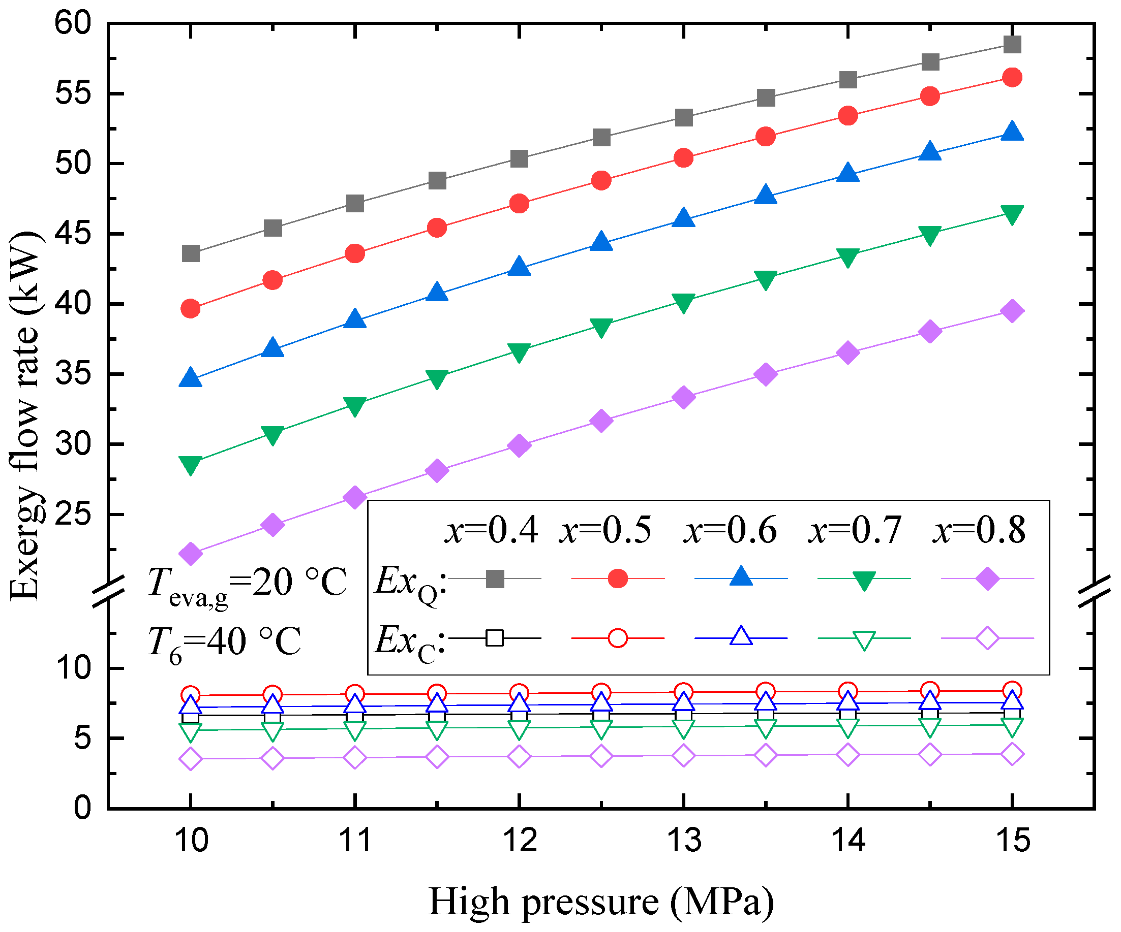
3.1.1. Effects of High Pressure

High pressure is a key operation parameter which influences the maximum cycle temperature, compression work, and corresponding cycle performance. The influence of high pressure on the highest and lowest cyclic temperature is illustrated in Figure 2, taking CO2/R134a as an example. In view of the fixed evaporation temperature of 20 °C, the low pressure is determined once the refrigerant mass fraction is regulated. Therefore, the maximum cycle temperature, appearing at the compressor outlet, increases with high pressure, due to the increasing pressure ratio. By comparing lines at different mass fractions, it is found that a lower CO2 mass fraction outputs higher temperature, mainly because evaporating pressure decreases with CO2 mass fraction under a given evaporating temperature. Different from pure refrigerant, a mixture could achieve a lower temperature at inlet than at outlet of the evaporator, in view of the temperature glide. Hence, the lowest temperature is obtained at evaporator inlet. The variation of high pressure has a limited influence on minimum cycle temperature, in which the minimum cycle temperature slightly decreases with high pressure. Nevertheless, the minimum cycle temperature is more affected by the refrigerant fraction and its temperature glide. The larger the temperature glide is, the lower the achievable cycle temperature.
The influence of high pressure on specific compression work and COPh is shown in Figure 3 and Figure 4, respectively. The specific compression work increases with high pressure, because of the increasing pressure ratio. Mixture with higher CO2 concentrations consume less compression work, due to the diminished gap between high and low pressure. COPh illustrates a negative relation with high pressure. A higher CO2 mass fraction yields a higher COPh, yet COPh is more affected by high pressure. For example, a decline of about 0.88 (4.26 to 3.38) is observed for COPh at 80% CO2 fraction, when high pressure ranges from 10 MPa to 15 MPa, while a decline of 0.39 (3.14 to 2.75) is observed for COPh at 40% CO2 fraction.

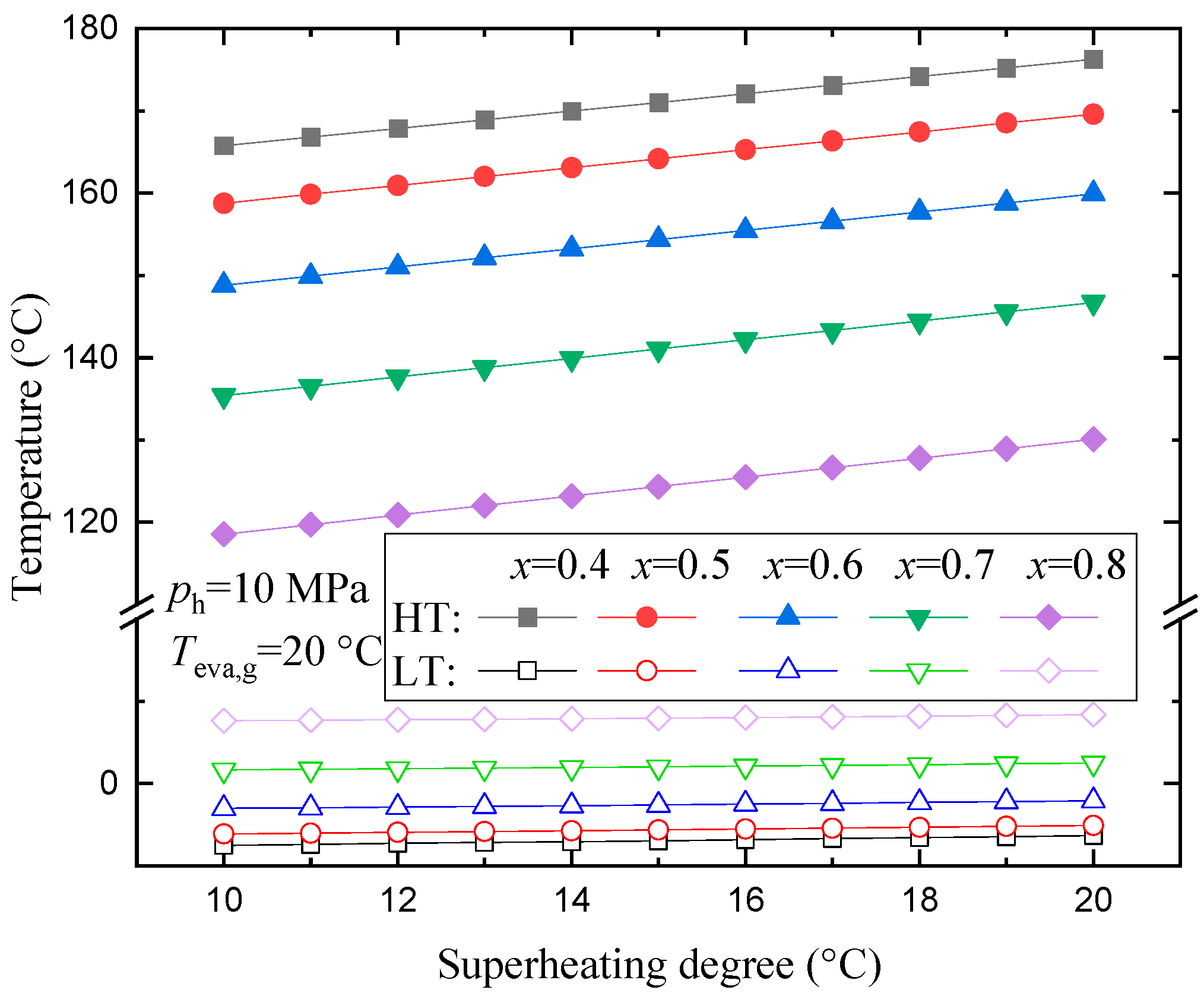
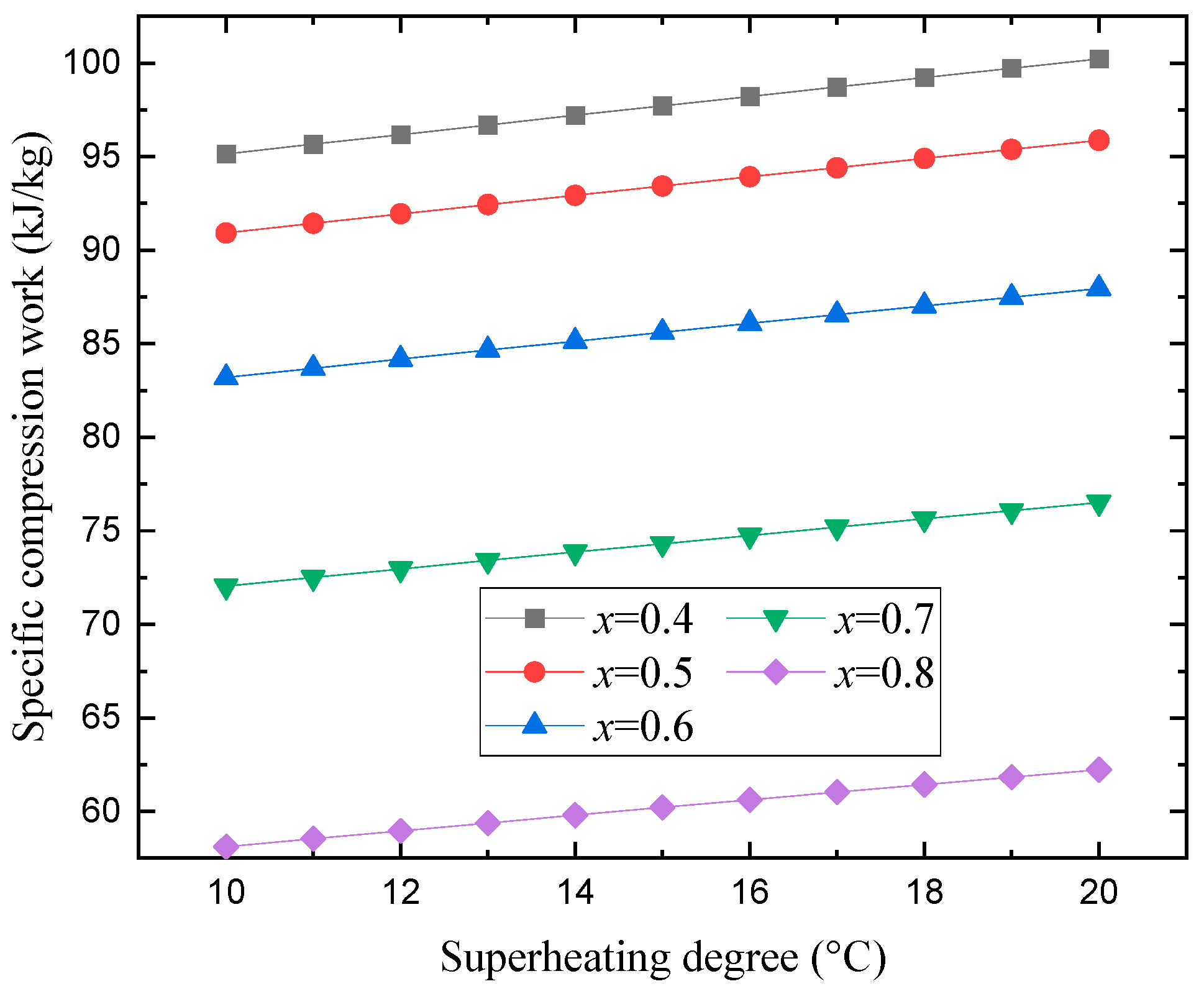
3.1.2. Effects of Superheating Degree

The superheating degree is also a key parameter that affects the compression process, as well as the heating temperature level and heat rejection amount. Figure 5 illustrates the influence of superheating degree on the highest and lowest cycle temperatures. The compressor outlet temperature increases linearly with superheating degree. As the superheating degree increases from 10 °C to 20 °C, the increment of the compressor outlet temperature under different mixture fractions falls within range of 10.5 °C to 11.5 °C. With regard to the lowest cycle temperature, it slightly increases, mainly within 1 °C, when the superheating degree ranges from 10 °C to 20 °C.
The influence of high pressure on specific compression work and COPh are shown in Figure 6 and Figure 7, respectively. With the increase of superheating degree, gas at compressor suction achieves a higher temperature but lower density, inducing higher compression work consumption. As the superheating degree increases by 10 °C, the specific compression work achieves an increase of about 4.2 kJ/kg to 5 kJ/kg. COPh decreases monotonically as the superheating degree increases. A mixture with a higher CO2 concentration yields higher COPh, but COPh shows a more sensitive relationship with the superheating degree. As the superheating degree increases from 10 to 20 °C, the decline of COPh can reach up to about 0.65.

3.1.3. Effects of Recuperator

The introduction of an internal recuperator is to regulate the temperature of the refrigerant and to partially recovery heat. In order to achieve a lower temperature before throttling, an approach that utilizes the latent heat of a two-phase refrigerant for recuperation is proposed. The approach temperature difference could be used to indicate the quantity of the two-phase heat transfer. Figure 8 illustrates the variation of the refrigerant’s temperature before and after throttling. As the approach temperature difference increases, more two-phase latent heat is utilized; hence, the temperature of the refrigerant before throttling decreases. Furthermore, the refrigerant accordingly achieves lower temperature after throttling. However, the approach temperature difference cannot increase without limit, and is restricted by the terminal pinch temperature difference. Duo to the fact that latent heat capacity is much higher than sensible specific heat capacity, liquid refrigerant achieves a temperature decrease of about 16 °C in conditions of an approach temperature difference of 4 °C, at CO2 mass fraction of 50%. As Figure 9 shows, the terminal temperature difference in cold end decreases significantly with the increase of approach temperature, laying constraints on the heat transfer of internal recuperation. Moreover, the heat transfer amount increases largely with approach temperature, which nearly doubles under an approach temperature difference of 3 °C.

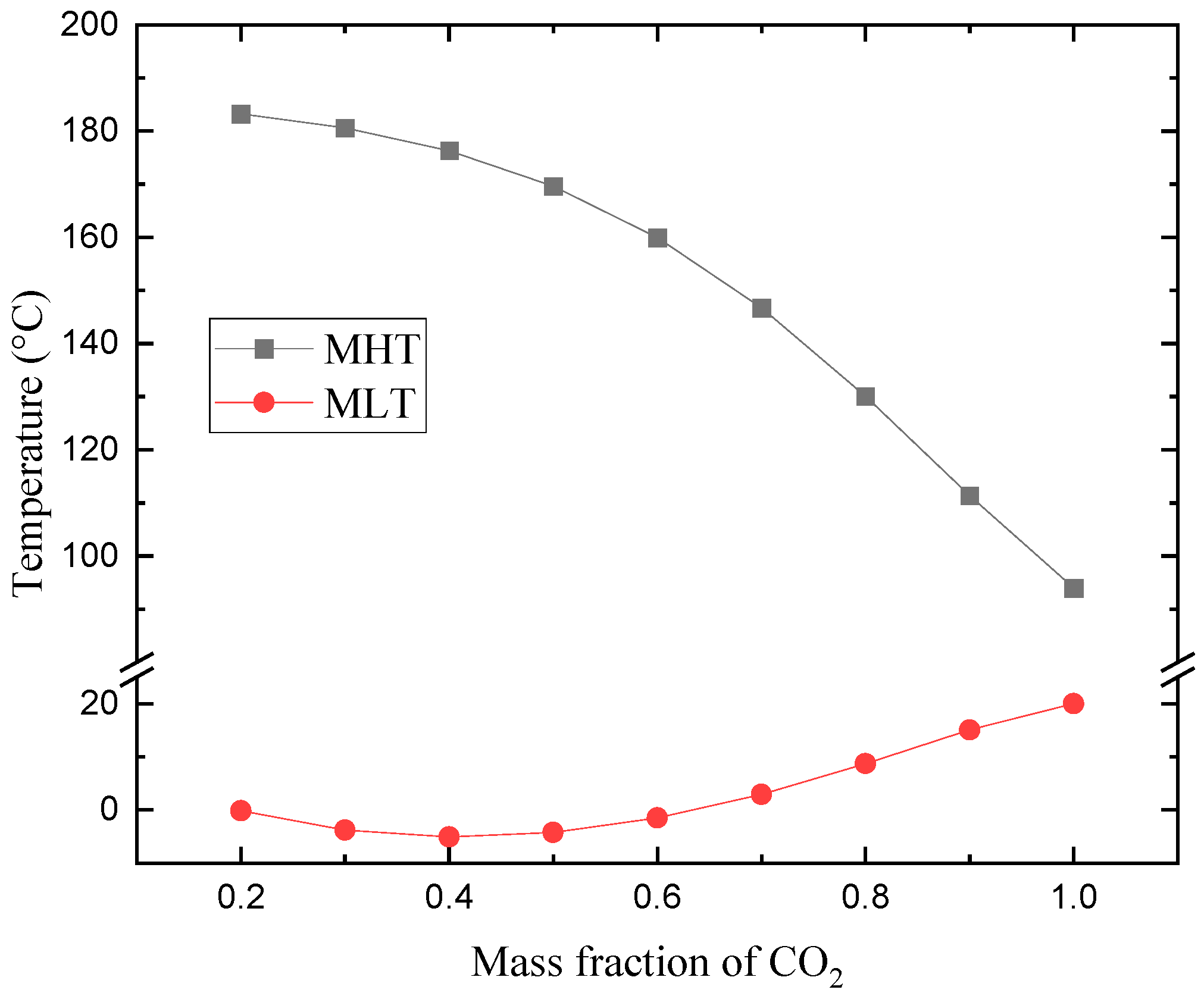
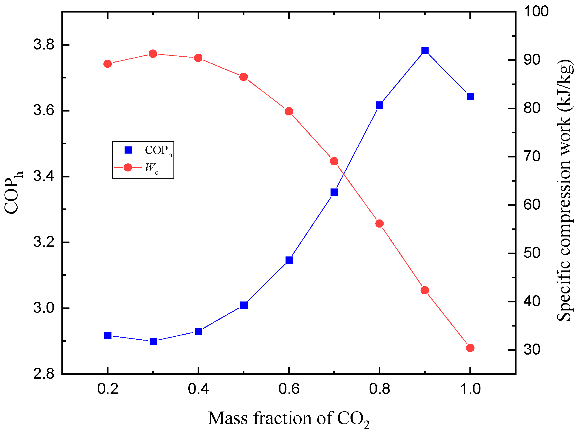
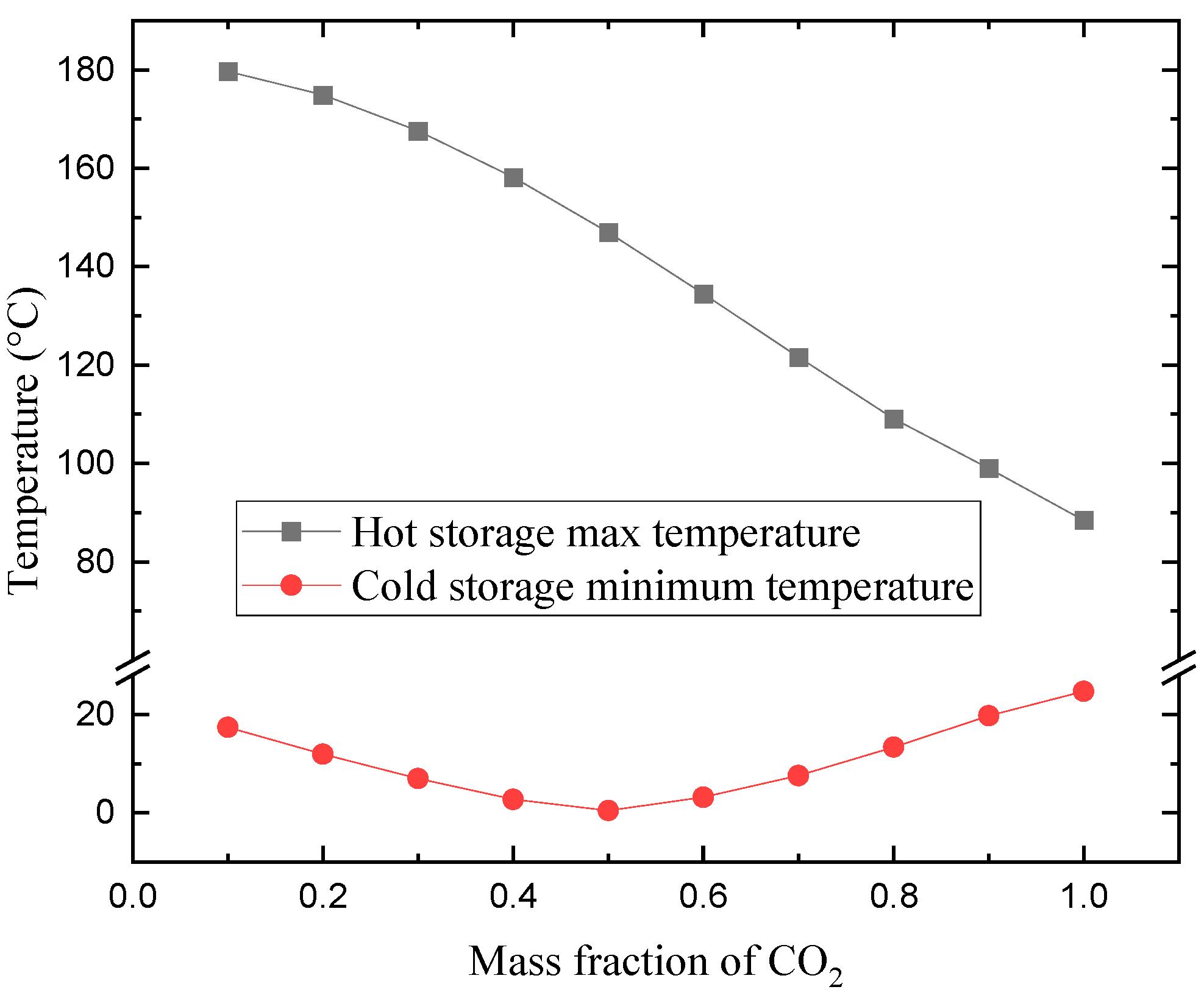
3.1.4. Effects of Refrigerant Fraction

As the mass fraction of CO2 changes, the mixture undergoes shifts in different critical parameters and evaporating temperature glide, exhibiting different fluid properties and producing various cycle performance. Figure 10 shows the influence of CO2 mass fraction on the highest and lowest cycle temperatures. Given the same high pressure, the maximum cycle temperature decreases as CO2 mass fraction increases, because the pressure ratio decreases. However, the lowest cycle temperature is more affected by the evaporating temperature glide. The lowest cycle temperature first decreases, and then increases, with increasing CO2 mass fraction, and a minimum value is obtained at a CO2 mass fraction of 0.4. Compared with the constant evaporating temperature of 20 °C for pure refrigerant, the mixture could achieve a significantly lower temperature of about −5 °C.
The influence of CO2 mass fraction on compression work and COPh is illustrated in Figure 11. As CO2 mass fraction increases, the specific compression work increases slightly initially, and then decreases significantly from a max value of 91.3 kJ/kg to 30.4 kJ/kg. COPh increases quickly, after an initial decrease, with CO2 mass fraction; the maximum value of 3.78 is obtained at a CO2 mass fraction of 90%. However, it shows a decline for pure CO2, mainly due to the fact that the pseudo-critical temperature of pure CO2 is relatively low, and large amount of sensible heat in the near-critical region cannot be utilized during heat rejection.

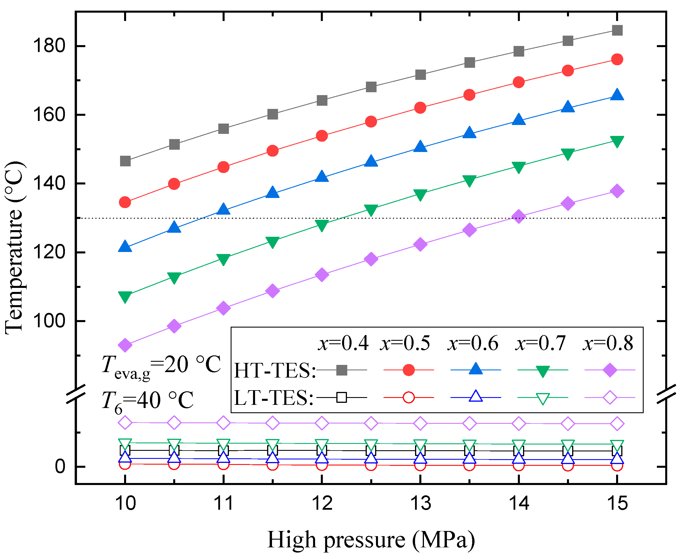
3.2. Coupling of Cycle with Hot and Cold Energy Storage Materials

Thermal matching between refrigerants and external heat sources plays an important role in determining the maximum hot and minimum cold TES temperature. Even though the maximum cycle temperatures are close under different operation conditions, the TES temperature may largely differ, because the pinch point may occur at different positions.
Figure 12 illustrates the temperature profiles in a gas cooler. During heat exchange, the specific heat capacity of the refrigerant changes, and the temperature profile is a curved line. The hot TES is pressurized water and the heat capacity almost keeps constant; hence, its temperature profile is nearly a straight line. There are two pinch points in the gas cooler; one is at the cold end and the other one appears during heat exchange. As the two pinch points become closer, the outlet temperature of TES is more affected by pinch restrict.
Figure 13 illustrates the effects of high pressure on the maximum hot and minimum cold TES temperature. The temperature of HT-TES increases monotonically with high pressure, but the growth rate slightly declines. In comparison with Figure 2, it is found that themaximum temperature of HT-TES is generally about 20 °C below the maximum cycle temperature, although the pinch point difference is only 5 °C. The temperature of LT-TES keep nearly constant with variation of high pressure.
Figure 14 illustrates the stored hot and cold exergy flow with variation of high pressure. According to Equations (11) and (12), exergy flow is related to the mass flow rate and terminal temperature of TES; therefore, the trend of the curves is in accordance with those in Figure 13. In this system, the heat exergy is rather higher than the cold exergy stored at the same time. The total exergy flow and corresponding efficiency is shown in Figure 15, and they both exhibit a positive correlation with high pressure. However, the exergy curve shows a lower growth rate at higher pressure.
The influence of the approach temperature difference on exergy efficiency is shown in Figure 16. As the approach temperature difference increases, it means that more cold energy is utilized for the subcooling of liquid refrigerant before throttling. According to the isenthalpic throttling process in Equation (5), the decline of enthalpy of liquid refrigerant before throttling will lead to an equivalent decline of the enthalpy value of a two-phase mixture, as well as a lower throttle temperature. As a consequence, the minimum LT-TES temperature is reduced and larger cold exergy flow rate is obtained. Exergy efficiency increases as the approach temperature difference increases.
Figure 17 shows the variation of maximum hot and minimum cold TES temperature with CO2 mass fraction. Temperature of HT-TES decreases monotonically as CO2 mass fraction increases. The temperature of LT-TES initially deceases, and then increases, with increasing of CO2 mass fraction, and a lowest value of 0.4 °C is obtained at a CO2 mass fraction of 50%. The influence of mass fraction on total exergy and exergy efficiency is shown in Figure 18. The total exergy increases initially, and then decreases, as CO2 mass fraction increases, and the maximum value of 54.1 kW is obtained at a CO2 mass fraction of 30%. However, the exergy efficiency decreases with the increase of CO2 mass fraction in the investigated condition.

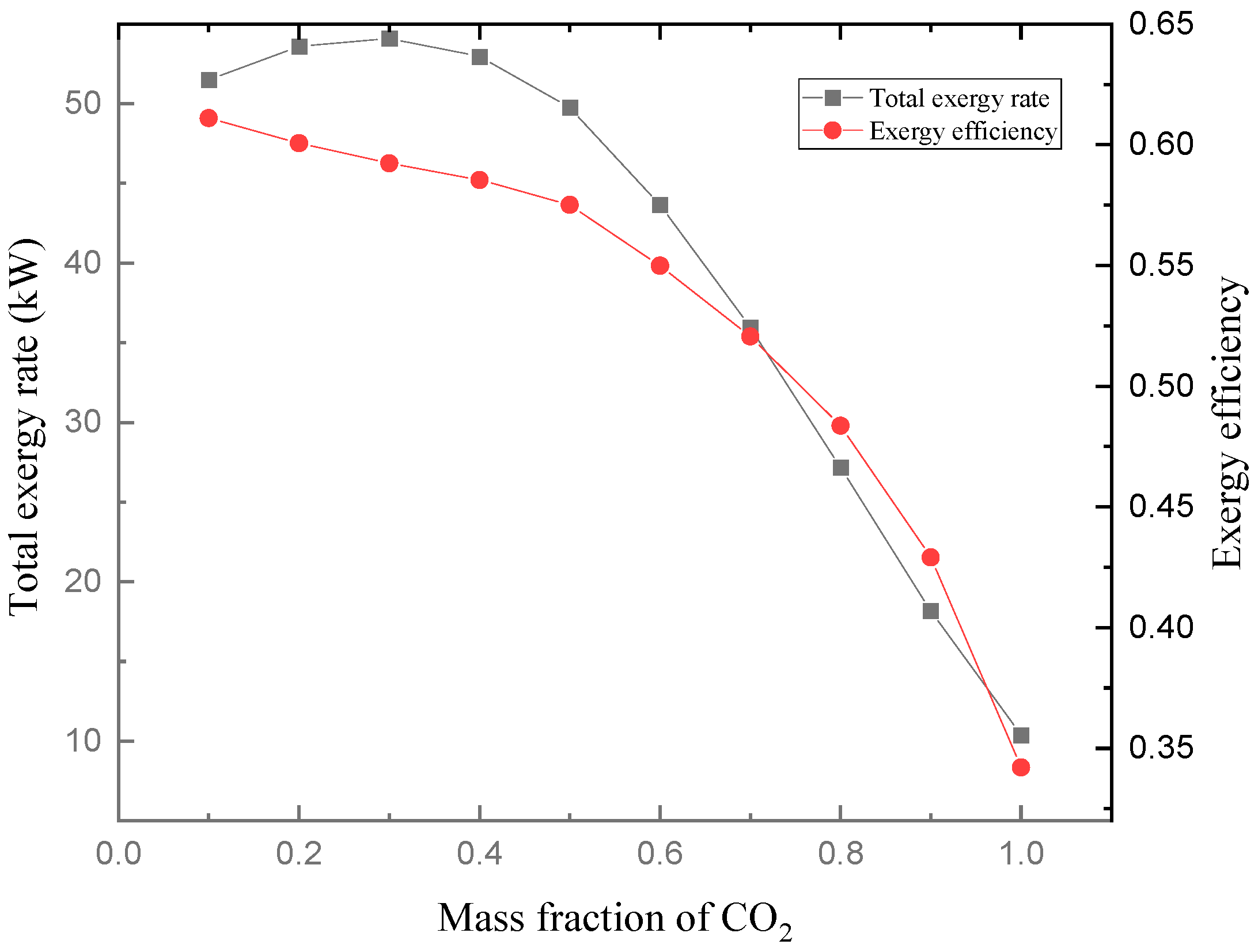
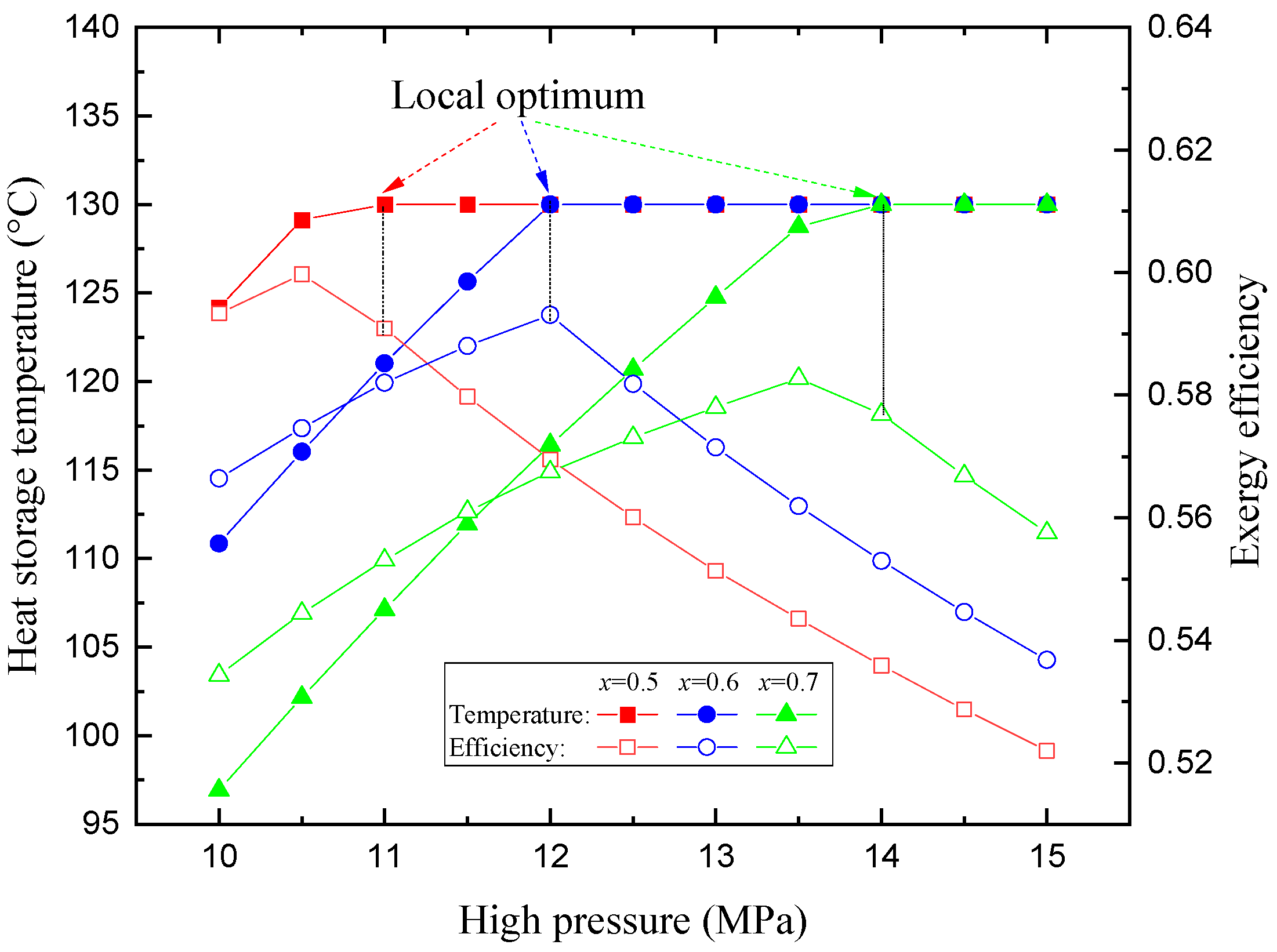
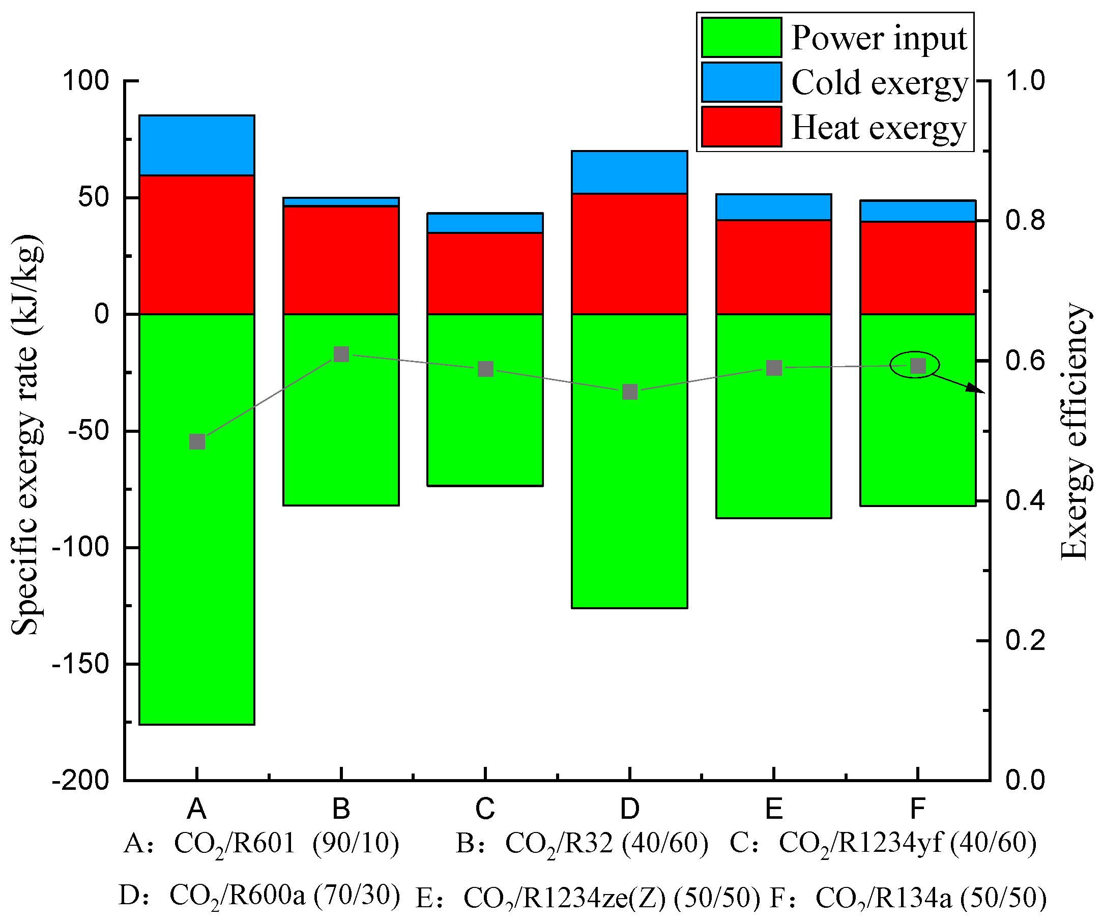
3.3. Optimization and Comparison

During heat storage or utilization, a stable hot TES temperature is desirable; hence, the temperature of a hot reservoir usually keeps constant at the default value. The TES could reach the target temperature under different operation parameters of the VCHP system; however, the system has different thermodynamic performances under different conditions. Therefore, performing an investigation on effective operation conditions to obtain the target thermal energy storage temperature is necessary. In this section, a target TES temperature of 130 °C is considered, and parametric optimization is carried out among different mixtures to obtain maximum exergy efficiency.
Figure 19 illustrates influence of high pressure on TES temperature and exergy efficiency. Different from Figure 13, maximum TES temperature here is set to be 130 °C. With increasing high pressure, TES temperature increases initially, and then keeps constant, despite the higher outlet temperature of the compressor. Exergy efficiency first increases, and then decreases, as high pressure increases. The decline of exergy efficiency is mainly because of the heat transfer irreversibility, which occurs due to the extending temperature gap between the refrigerant and the TES material. The local optimum position, where TES reaches a temperature of 130 °C for the first time, is marked in the figure.
Figure 20 illustrates the comparative results among different mixtures. CO2/R32, CO2/R1234ze(Z), and CO2/R134a show the highest exergy efficiency, at 61.0%, 59.1%, and 59.4%, respectively. CO2/R601 has the poorest efficiency value, at 48.5%, due to its large compression work. Nonetheless, CO2/R601 produces the largest proportion of cold exergy to total exergy, up to 30.1%. The temperature of LT-TES can reach as low as −32.4 °C, followed by CO2/R600a, with a cold exergy proportion of 26.1% and LT-TES temperature of −18 °C. CO2/R32 produces the lowest cold exergy, with a proportion of only 7.3% to total exergy, and the corresponding LT-TES temperature is 16.1 °C. Consequently, a larger evaporating temperature glide favor higher cold exergy and lower LT-TES temperature.

4. Conclusions

This work aims to conduct a thermodynamic evaluation of heat pumps using CO2-based mixtures from a view point of heat and cold generation. An internal recuperation cycle with two-phase latent energy utilization is proposed. First, a comprehensive parametric investigation is carried out for the transcritical heat pump cycle using CO2/R134a as an example. Subsequently, the coupling behavior of the heat pump cycle, with external TES materials, is evaluated to assess the cold and heat energy generated in the VCHP system. Finally, optimization and a comparative study are performed among different CO2-based mixtures, given a constant HT-TES temperature of 130 °C. Based on the study, following conclusions can be drawn:
(1)
The minimum cycle temperature is mainly affected by refrigerant composition, with little influence from high pressure. The maximum cycle temperature benefits from higher pressure, a higher superheating degree, and a lower CO2 mass fraction, while COPh shows an opposite relationships with these parameters.
(2)
By utilizing latent heat of two-phase refrigerant for recuperation, the refrigerant achieves a lower temperature after throttling, without additional energy consumption. However, the utilization of latent heat is restricted by the cold terminal temperature difference of the recuperator.
(3)
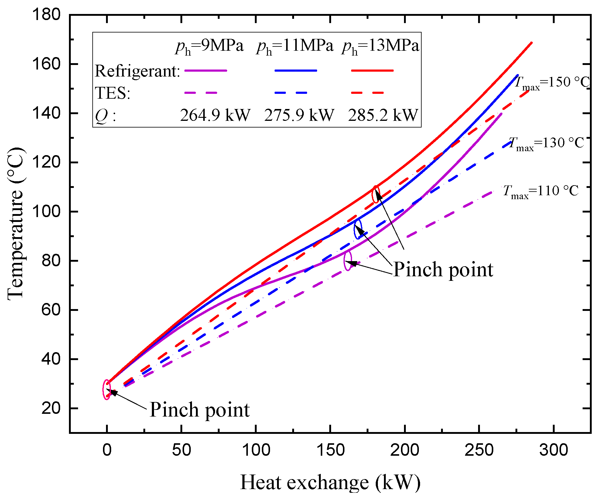
The temperature of TESs is affected by the cycle operation condition, as well as thermal matching between the refrigerant and the TES material. An internal pinch point in the gas cooler induces larger terminal difference in the hot end. Exergy efficiency commonly increases as high pressure increases.
(4)
In the condition of a fixed HT-TES temperature of 130 °C, CO2/R32 (90/10) produces the maximum exergy efficiency of 61.0% among mixtures under optimization. A larger evaporating temperature glide is suggested to output higher cold exergy and lower LT-TES temperature. CO2/R600a produces the largest cold exergy proportion of 30.1%, as well as the lowest temperature of −32.4 °C for LT-TES.

Author Contributions

C.L., conceptualization, investigation, methods, formal analysis, and writing—original draft; Y.W. (Yongzhen Wang), project administration, supervision, funding acquisition, investigation, and writing—review and editing; Q.G., formal analysis and resources. Y.W. (Youtang Wang), supervision and writing—review and editing; H.C., resources. All authors have read and agreed to the published version of the manuscript.

Funding

The authors gratefully acknowledge the support from the Natural Science Foundation of Shandong Province (No. ZR2022QE166), the Technological Innovation Capability Elevation Project of Small and Medium-size Technology-based Enterprise of Shandong Province (No. 2022TSGC2262), and National Natural Science Foundation of China (Project No. 52006114).

Data Availability Statement

Data will be made available on request.

Conflicts of Interest

The authors declare that they have no known competing financial interests or personal relationships that could have appeared to influence the work reported in this paper.

Nomenclature

E ˙ exergy rate, kW
hspecific enthalpy, kJ/kg
m ˙ mass flow rate, kg/s
ppressure, MPa
Q ˙ heat flow rate, kW
sspecific entropy, kJ/(kg·K)
Ttemperature, °C
W ˙ power consumed, kW
Abbreviations
COPhheating coefficiency of performance
HThigh temperature
LTlow temperature
TESthermal energy storage
VCHPvapor compression heat pump
Subscripts
0ambient state
1, 2, 3…states in cycle
Ccold
Hheat
ininlet
netnet
outoutlet
pppinch point
tturbine
tottotal
Greek symbols
ηexexergy efficiency

References

  1. Ayachi, F.; Tauveron, N.; Tartière, T.; Colasson, S.; Nguyen, D. Thermo-Electric Energy Storage involving CO2 transcritical ground heat storage. Appl. Therm. Eng. Des. Process. Equip. Econ. 2016, 108, 1418–1428. [Google Scholar] [CrossRef]
  2. Mercangoez, M.; Hemrle, J.; Kaufmann, L.; Z’Graggen, A.; Ohler, C. Electrothermal energy storage with transcritical CO2 cycles. Energy 2012, 45, 407–415. [Google Scholar] [CrossRef]
  3. Carro, A.; Chacartegui, R.; Ortiz, C.; Carneiro, J.; Becerra, J.A. Integration of energy storage systems based on transcritical CO2: Concept of CO2 based electrothermal energy and geological storage. Energy 2022, 238, 121665. [Google Scholar] [CrossRef]
  4. Belazreg, A.; Abderrahmane, A.; Qasem, N.A.; Sene, N.; Mohammed, S.; Younis, O.; Guedri, K.; Nasajpour-Esfahani, N.; Toghraie, D. Effect of Y-shaped fins on the performance of shell-and-tube thermal energy storage unit. Case Stud. Therm. Eng. 2022, 40, 102485. [Google Scholar] [CrossRef]
  5. Miansari, M.; Nazari, M.; Toghraie, D.; Akbari, O.A. Investigating the thermal energy storage inside a double-wall tank utilizing phase-change materials (PCMs). J. Therm. Anal. Calorim. 2020, 139, 2283–2294. [Google Scholar] [CrossRef]
  6. Frate, G.F.; Antonelli, M.; Desideri, U. A novel Pumped Thermal Electricity Storage (PTES) system with thermal integration. Appl. Therm. Eng. Des. Process. Equip. Econ. 2017, 121, 1051–1058. [Google Scholar] [CrossRef]
  7. Frate, G.F.; Ferrari, L.; Desideri, U. Multi-criteria investigation of a pumped thermal electricity storage (PTES) system with thermal integration and sensible heat storage. Energy Convers. Manag. 2020, 208, 112530. [Google Scholar] [CrossRef]
  8. Zhang, M.; Shi, L.; Hu, P.; Pei, G.; Shu, G. Carnot battery system integrated with low-grade waste heat recovery: Toward high energy storage efficiency. J. Energy Storage 2023, 57, 106234. [Google Scholar] [CrossRef]
  9. Dumont, O.; Frate, G.F.; Pillai, A.; Lecompte, S.; Lemort, V. Carnot battery technology: A state-of-the-art review. J. Energy Storage 2020, 32, 101756. [Google Scholar] [CrossRef]
  10. Obara, S. Energy storage device based on a hybrid system of a CO2 heat pump cycle and a CO2 hydrate heat cycle. Renew. Sustain. Energy Rev. 2023, 179, 113290. [Google Scholar] [CrossRef]
  11. Hakkaki-Fard, A.; Aidoun, Z.; Ouzzane, M. Applying refrigerant mixtures with thermal glide in cold climate air-source heat pumps. Appl. Therm. Eng. 2014, 62, 714–722. [Google Scholar] [CrossRef]
  12. Guo, H.; Gong, M.; Qin, X. Performance analysis of a modified subcritical zeotropic mixture recuperative high-temperature heat pump. Appl. Energy 2019, 237, 338–352. [Google Scholar] [CrossRef]
  13. Cui, Q.; Wang, C.; Gao, E.; Zhang, X. Pinch point characteristics and performance evaluation of CO2 heat pump water heater under variable working conditions. Appl. Therm. Eng. 2022, 207, 118208. [Google Scholar] [CrossRef]
  14. Wang, X.; Li, H.; Wang, Y.; Zhao, J.; Zhu, J.; Zhong, S.; Li, Y. Energy, exergy, and economic analysis of a data center energy system driven by the CO2 ground source heat pump: Prosumer perspective. Energy Convers. Manag. 2021, 232, 113877. [Google Scholar] [CrossRef]
  15. White, S.D.; Yarrall, M.G.; Cleland, D.J.; Hedley, R.A. Modelling the performance of a transcritical CO2 heat pump for high temperature heating (Reprinted). Int. J. Refrig. 2002, 25, 479–486. [Google Scholar] [CrossRef]
  16. Sun, Z.; Cui, Q.; Wang, Q.; Ning, J.; Xu, Y. Experimental study on CO2/R32 blends in a water-to-water heat pump system. Appl. Therm. Eng. 2019, 162, 114303. [Google Scholar] [CrossRef]
  17. Dai, B.; Dang, C.; Li, M.; Tian, H.; Ma, Y. Thermodynamic performance assessment of carbon dioxide blends with low-global warming potential (GWP) working fluids for a heat pump water heater. Int. J. Refrig. 2015, 56, 1–14. [Google Scholar] [CrossRef]
  18. Ganesan, P.; Eikevik, T.M. New zeotropic CO2-based refrigerant mixtures for cascade high-temperature heat pump to reach heat sink temperature up to 180 °C. Energy Convers. Manag. X 2023, 20, 100407. [Google Scholar] [CrossRef]
  19. Gómez-Hernández, J.; Grimes, R.; Briongos, J.V.; Marugán-Cruz, C.; Santana, D. Carbon dioxide and acetone mixtures as refrigerants for industry heat pumps to supply temperature in the range 150–220 °C. Energy 2023, 269, 126821. [Google Scholar] [CrossRef]
  20. Zhang, F.; Zhu, Y.; Li, C.; Jiang, P. Thermodynamic optimization of heat transfer process in thermal systems using CO2 as the working fluid based on temperature glide matching. Energy 2018, 151, 376–386. [Google Scholar] [CrossRef]
  21. Zühlsdorf, B.; Jensen, J.K.; Cignitti, S.; Madsen, C.; Elmegaard, B. Analysis of temperature glide matching of heat pumps with zeotropic working fluid mixtures for different temperature glides. Energy 2018, 153, 650–660. [Google Scholar] [CrossRef]
  22. Frate, G.F.; Ferrari, L.; Desideri, U. Rankine Carnot Batteries with the Integration of Thermal Energy Sources: A Review. Energ. 2020, 13, 4766. [Google Scholar] [CrossRef]
  23. Rodríguez-deArriba, P.; Crespi, F.; Sánchez, D.; Muñoz, A.; Sánchez, T. The potential of transcritical cycles based on CO2 mixtures: An exergy-based analysis. Renew. Energy 2022, 199, 1606–1628. [Google Scholar] [CrossRef]
  24. Binbin, Y.U.; Yang, J.; Wang, D.; Shi, J.; Chen, J. Modeling and theoretical analysis of a CO2-propane autocascade heat pump for electrical vehicle heating. Int. J. Refrig. 2018, 95, 146–155. [Google Scholar]
  25. Li, C.; Pan, L.; Wang, Y. Thermodynamic optimization of Rankine cycle using CO2-based binary zeotropic mixture for ocean thermal energy conversion. Appl. Therm. Eng. 2020, 178, 115617. [Google Scholar] [CrossRef]
Figure 1. Schematic of a VCHP system for simultaneous heat and cold storage.
Energies 16 06587 g001
Figure 2. Effects of high pressure on the highest and lowest cycle temperatures.
Energies 16 06587 g002
Figure 3. Effects of high pressure on specific compression work.
Energies 16 06587 g003
Figure 4. Effects of high pressure on COPh.
Energies 16 06587 g004
Figure 5. Effects of superheating degree on the highest and lowest cycle temperature.
Energies 16 06587 g005
Figure 6. Effects of superheating degree on specific compression work.
Energies 16 06587 g006
Figure 7. Effects of superheating degree on COPh.
Energies 16 06587 g007
Figure 8. Effects of approach temperature difference on refrigerant temperature.
Energies 16 06587 g008
Figure 9. Temperature distribution of recuperator. The blue and red lines represent cold and hot fluids, respectively.
Energies 16 06587 g009
Figure 10. Effects of CO2 mass fraction on the highest and lowest cycle temperature.
Energies 16 06587 g010
Figure 11. Effects of CO2 mass fraction on compression work and COPh.
Energies 16 06587 g011
Figure 12. Thermal matching between refrigerant and hot TES in a gas cooler.
Energies 16 06587 g012
Figure 13. Effects of high pressure on maximum hot and minimum cold storage temperatures.
Energies 16 06587 g013
Figure 14. Effects of high pressure on hot and cold exergy flow rate.
Energies 16 06587 g014
Figure 15. Effects of high pressure on total exergy flow rate and efficiency.
Energies 16 06587 g015
Figure 16. Effects of approach temperature difference on exergy efficiency.
Energies 16 06587 g016
Figure 17. Effects of CO2 mass fraction on maximum hot and minimum cold storage temperatures.
Energies 16 06587 g017
Figure 18. Effects of CO2 mass fraction on total exergy rate and efficiency.
Energies 16 06587 g018
Figure 19. Variation of TES temperature and corresponding exergy efficiency with high pressure under various mixture composition.
Energies 16 06587 g019
Figure 20. Comparison among different mixtures under optimum design condition.
Energies 16 06587 g020
Table 1. Specifications of the model.
ParameterValue
Heat pump cycle
High pressure, ph (MPa)≥1.1 pcrit
Evaporating temperature, Teva (°C)20
Mass flow rate of refrigerant, (kg/s) 1
Pinch point temperature difference, ∆Tpp (°C)5
Approach temperature difference, ∆Tap (°C)0–5
Superheating degree, ∆Tsh (°C)5–20
Compressor isentropic efficiency, ηcom0.85
Storage
Hot storage max temperature, Ths,max (°C)130
Cold storage temperature, Tcs (°C)Variable
Ambient temperature, Tamb (°C)25
Disclaimer/Publisher’s Note: The statements, opinions and data contained in all publications are solely those of the individual author(s) and contributor(s) and not of MDPI and/or the editor(s). MDPI and/or the editor(s) disclaim responsibility for any injury to people or property resulting from any ideas, methods, instructions or products referred to in the content.

