Article

Intelligent Monitoring Platform and Application for Building Energy Using Information Based on Digital Twin

1
School of Mechanical Engineering, Tongji University, Shanghai 200092, China
2
Shanghai Foreign Economic and Trade Engineering Corp., Ltd., Shanghai 200070, China
*
Author to whom correspondence should be addressed.
Energies 2023, 16(19), 6839; https://doi.org/10.3390/en16196839
Submission received: 31 August 2023 / Revised: 17 September 2023 / Accepted: 19 September 2023 / Published: 27 September 2023

Abstract

:
With the development and popularization of the Internet of Things, big data, cloud computing, and other technologies, Digital twin technology (DTT) is increasingly applied to building operation and maintenance (O&M). However, most of the research focuses on building energy consumption, safety, and other management, and relatively little research on the monitoring of building terminal energy using information. The information is closely related to occupants’ behavior, such as air conditioning, lighting, shading, window status information, as well as personnel number and location, and it has a great impact on building energy consumption. Due to different occupants’ behaviors, the level of building energy consumption varies several times or even more. Take an office building as an example. Based on digital twin technology, the framework of building energy using intelligent monitoring is constructed. It mainly includes four parts, namely building physical space, virtual twin space, predictive control simulation engine, and twin big data. For each part, functions are realized through building Information Modelling (BIM), smart sensors, and Internet of Things (IoT) technologies. Based on the standard framework and every function realization method, the DTT can used for building O&M effectually. The application of building an intelligent control system based on the occupants’ characteristics is simulated and analyzed in Designbuilder software 6.1.2. The results show that the digital technology application in building intelligent control systems can realize maximum energy saving for 30%. However, the DTT in building O&M is not widely used now. There is a lot of research to be completed in the future.

1. Introduction

Building energy consumption is a major contributor to carbon emissions. Despite governmental efforts to lower energy use and emissions, the trend continues to rise. The operation and maintenance (O&M) phase is the largest energy consumption throughout the building lifecycle, and it is about 15–25 times more than the design and construction phase [1]. Specific to the O&M phase, there are many facilities like HVAC, lighting, equipment, etc., and the management is complex. The traditional building automation systems (BAS) only realize the switch control for the HVAC equipment, and it lacks effective control according to the end use. Effective control and management can improve the indoor environment and reduce the level of building energy consumption. Digital twin technology (DTT) is increasingly applied to building operation and maintenance (O&M). Building Information Modelling (BIM) and Internet of Things (IoT) technologies are the core technologies. The BIM model is used to reflect the real-time running state of physical reality, the IoT and smart sensors are used to collect massive data, the collected big data will be analyzed, and it will provide data support for management and decision-making for building management. Compared with traditional building automation systems (BAS), digital operation and maintenance have obvious advantages in management, response speed, and work efficiency.
The DTT enables the physical world and corresponding digital virtual world to interact, receive real-time information from the physical world, drive the real physical world to the intelligent brain of the physical world, and make prediction decisions [2,3,4]. DTT was first verified in aerospace, intelligent manufacturing, and other engineering fields [5,6], and then it was gradually applied in the urban management field [7], but relatively little research in architecture [8]. With the development of building information technology, DTT is used in the building, and it can present a new opportunity to better implement building performance. A virtual-real mapping frame system is researched, which can realize the integrated management and control method for buildings [9]. The operation cost management of green buildings can be realized based on DTT [10]. The connection of the digital building twin with blockchain-based smart contracts to execute performance-based digital payments [11]. Creating an accurate digital model can integrate the experimental physical reality and use it to study the structural response of the system, its preventive maintenance, and strengthening operations [12]. The modeling methodology is also used by the energy domain to support the development of a digital twin for a multifunctional building element [13]. Using the Building Information Model (BIM) to explore the key techniques of Digital Twins and to realize building energy efficiency [14]. Developing a conceptual framework for the application of digital twin technologies to revamp building operation and maintenance processes [15]. The DTT application in the architecture field mainly focuses on the concept, framework, implementation method, and application advantage analysis, and it is beginning to apply in HVAC user behavior. The application status of DTT is shown in Figure 1.
3D virtual modeling and their reflection with physical buildings and equipment systems are important parts of digital operation and maintenance. However, the digital twin platform lacks a standard technology system to promote the application. For the air conditioning system to be optimized and energy consumption minimized, the real-time monitoring and information feedback from occupants’ behavior and equipment use need to be researched, and the application also needs to be promoted.

2. The Implementation of Digital Twin for Energy Using

2.1. The Digital Twin Composition

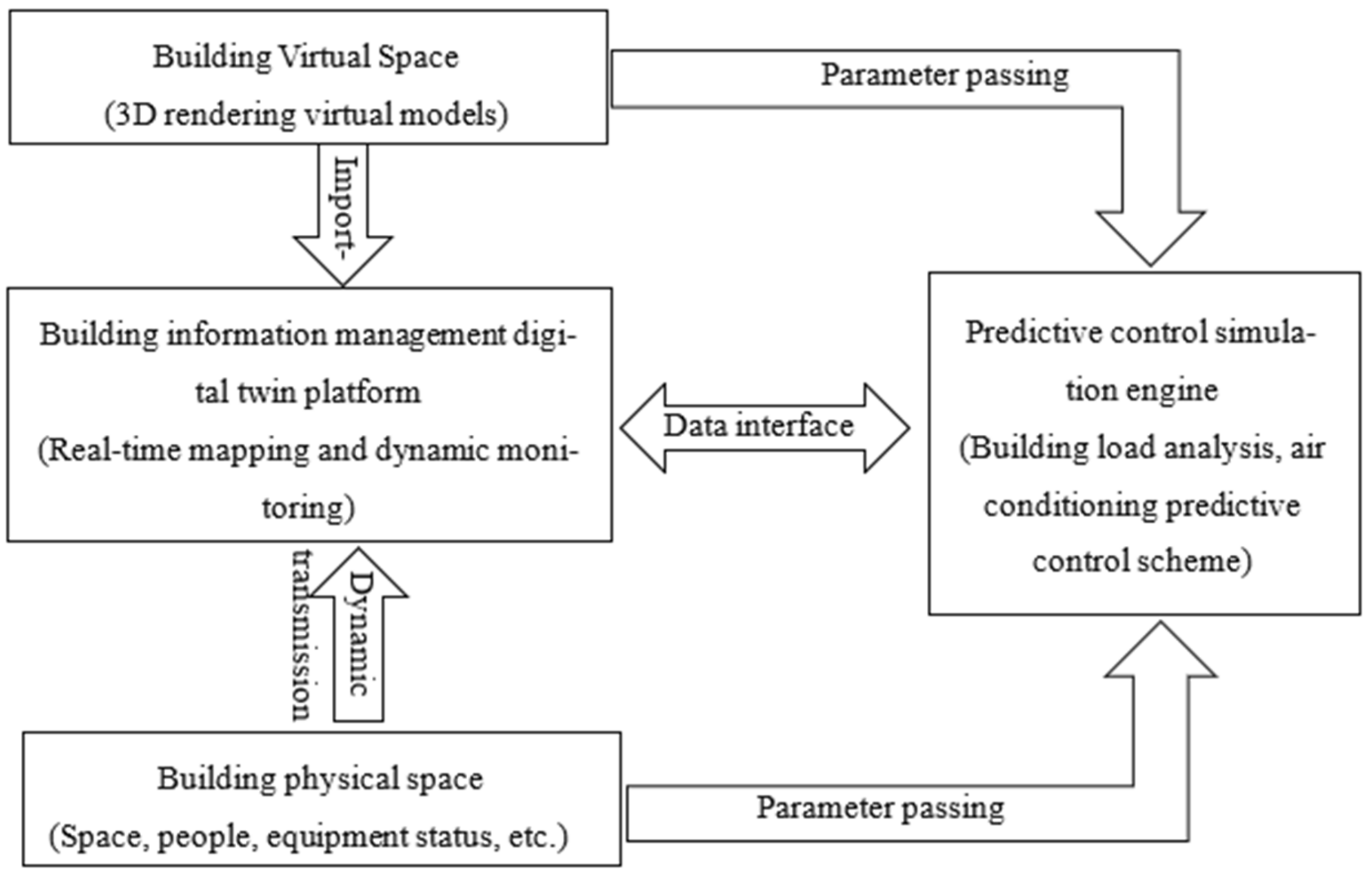
DTT is used in building management. It can create a bridge between the physical and virtual space and across different hierarchies and scales. The mathematical models, smart sensors, and historical operation data mirror and reflect the real building facilities and predict the performance of the corresponding building’s physical space. The standard framework of DTT application includes building physical space, virtual twin space, predictive control simulation engine, twin big data, etc., and the mirror and reflect from the building physical space to the twin space is realized layer by layer. The digital twin system framework is shown in Figure 2. Building physical space is the basis of a digital twin system. Various types of sensors are used to monitor the changes in the physical space state so that the environmental data can be truly fed back to the virtual twin space. The virtual twin space is to complete the mirror and reflect the building’s real space, which integrates the information of geometry, physics, behavior, rules, and other dimensions of the building’s physical space and truly depicts, simulates, and maps the physical space. A predictive control simulation engine is the core of digital twin applications, and it can provide prediction and decision for the physical world and drive the physical world in turn. Digital twin data platform including building physical space, virtual twin space, predictive control simulation engine, and other domain knowledge. With the operation of the digital twin system to continuously obtain, update, and optimize, the operation of each component is promoted.
The building digital twin system aims to combine DTT with indoor thermal environment prediction and intelligent building operation and maintenance. The space temperature, air environment quality, occupant behavior, and other information monitored can provide data support for building efficient control and reduce energy consumption while ensuring user comfort.

2.2. Implementation Method of Digital Twin System for Building Management

Traditional BAS is the main automatic control system used to maintain the normal operation of public buildings. For the DTT platform, the building operation and load status information will be solved. The existing management system needs to integrate, store, and manage, and a series of interfaces and engines need to process to provide the underlying data for the 3D visual building information model. Virtual twin platform can realize model mirror and reflect, operation browsing, sensor data access, simulation prediction, and decision. It can effectively reflect the building characteristics obtained and update the sensors monitoring data. According to occupants’ location and number and the current indoor temperature, the next time temperature value will be obtained through the simulation and prediction process, and management decisions are made according to the prediction results.
Based on the digital twin visual platform, the monitoring data of equipment and environment in the building will be improved. The heterogeneous sensor network is designed and realized by using various wireless communication modes. The detection scheme is improved to ensure that the collected data can be gathered for the digital twin management platform. The whole system is realized by ZigBee intelligent acquisition terminal, wireless sensor network (WSNs), etc. WSNs summarize the sensors’ data to the network node, providing real-time and accurate information for the building operation and maintenance party. It has been widely used for building monitoring, which has low cost, real-time performance, good discoverability for emergencies, a large coverage rate, and high practical value.
The virtual twin platform is built on the basis of the three-dimensional building model. The building’s geometric size, style, and structure will be rendered using 3ds max, and the in.fbx file will be obtained and then imported into the Unity 3D engine. At the same time, the texture file is imported to complete the static model mapping. The space-time information and state information need to enter Unity through C# script files to drive the virtual twin model update and complete the dynamic virtual-real mapping. The sensor data accessing function is completed through scripting data, and personnel location, personnel number, and temperature in virtual space are displayed. The flow chart of the virtual twin platform constructed with Unity 3D is shown in Figure 3.
Building indoor and outdoor environmental parameters, occupants’ behavior is monitored by smart sensors, and the data are embedded into the digital twin platform. The built environment is analyzed and evaluated by the computer simulation software. Through computer simulation technology, the control information of air-conditioning, lighting, shading, windows, etc., will be feedback, and the building will achieve intelligent control.

3. The Building Information Monitoring Case Base on DTT

3.1. Building Introduction

The demonstration building is located in the center of Hongkou business district, Shanghai, and it was completed in 1992. The total area of the building is 49,666 m2, which is divided into two areas. Area A is for an office room, with 30 floors above ground and 1 semi-underground floor. The layer area is about 1170 m2, and the height is 3.1 m. In 2017, the building was renovated, including the envelope structure, HVAC equipment, lighting equipment, indoor environment monitoring system, etc. Two standard floors, 22 and 24, were selected as a demonstration to monitor the indoor environment, occupant behavior, and equipment use, as well as the outdoor weather.

3.2. Digital Twin Operation and Maintenance Platform

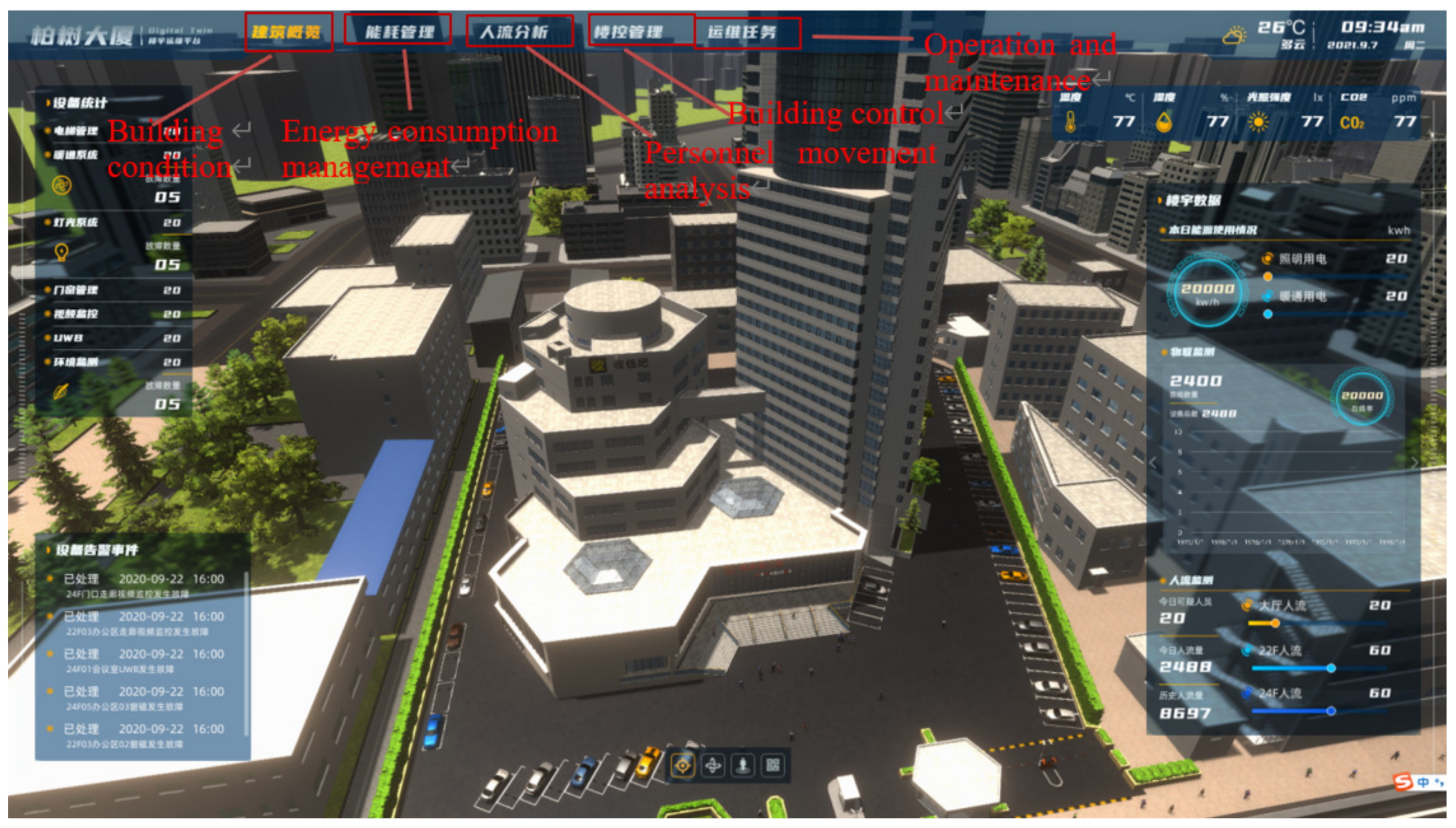
The building devices and spaces of layers 22 and 24 are rendered, and the model is imported into the Unity 3D engine to realize the real-time connection between the virtual twin space and physical space so that the virtual twin platform can be updated continuously. Building a digital twin operation and maintenance virtual platform can realize the display of the building’s internal and surrounding environment, equipment information statistics, alarm list, weather station information, air quality data, building energy consumption statistics, equipment status, and people number and location information statistics. The operation and maintenance interface of the building digital twin virtual platform is shown in Figure 4.
The building digital twin operation and maintenance platform transmits data through a network of the end devices. Each terminal monitoring device, computing server, and display platform are connected by Cat.5 twisted-pair cable, RS485 serial communication standard protocol, WIFI, and ZigBee. Data analysis and model comparison are carried out on the server side, and the energy consumption of the terminal equipment is intelligently controlled to achieve the building’s energy-saving target.
The building digital twin virtual platform can display the data of all devices in real-time and feedback to the equipment based on the control logic. The functions are described as follows.
(1)
Indoor environment monitoring system
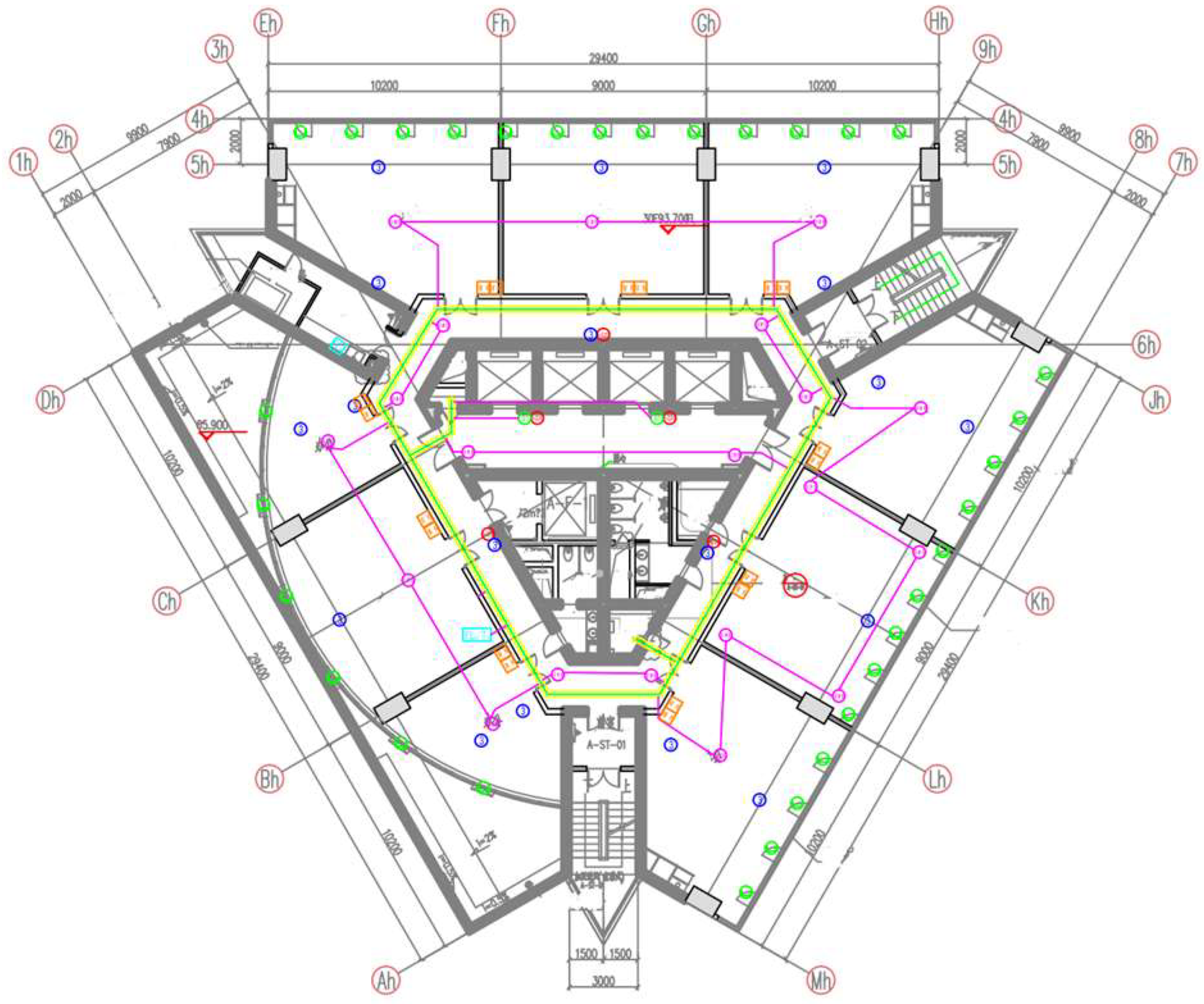
Indoor environment sensor detection parameters include illumination, temperature, humidity, carbon dioxide, PM2.5, TVOC, etc., and there are three multi-parameter sensors on floors 22 and 24. In addition, there are 18 three-parameter sensors that mainly monitor temperature and humidity, illumination. The environmental sensor node is composed of a microprocessor, multi-sensor module, ZigBee module, and peripheral circuit. The data are transmitted to the remote server through the TCP protocol in the network envelope, and it is saved for data processing. So, the indoor environment parameter information can be read in real-time on the digital twin virtual platform, and it can provide data support for air conditioning load prediction. The visual effect of environmental monitoring is shown in Figure 5. The environmental monitoring sensor layout is shown in Figure 6.
(2)
Personnel location system
Occupants’ accurate positioning will be obtained through an Ultra-Wideband (UWB) sensor. UWB positioning system is composed of four parts, including positioning base station, positioning label, synchronization controller, and solution engine (server). When UWB base stations are deployed, the number of base stations, the distribution location, and the positioning area are necessary to consider [16]. Different numbers of base stations will affect the positioning accuracy. When the number of base stations is changed from 3 to 4, the positioning error can be reduced from meters to centimeters. In addition, the base station should be arranged in a shape close to a regular polygon, and it is necessary to cover as much as possible all the area. Based on this principle, 20 UWB base stations are arranged on the 22nd and 24th floors, respectively, and occupants’ accurate positioning is realized through the positioning labels equipped. Air conditioning can be controlled according to the location and number of personnel. The UWB sensor plane and application are shown in Figure 6 and Figure 7.
(3)
Door and window intelligent management system
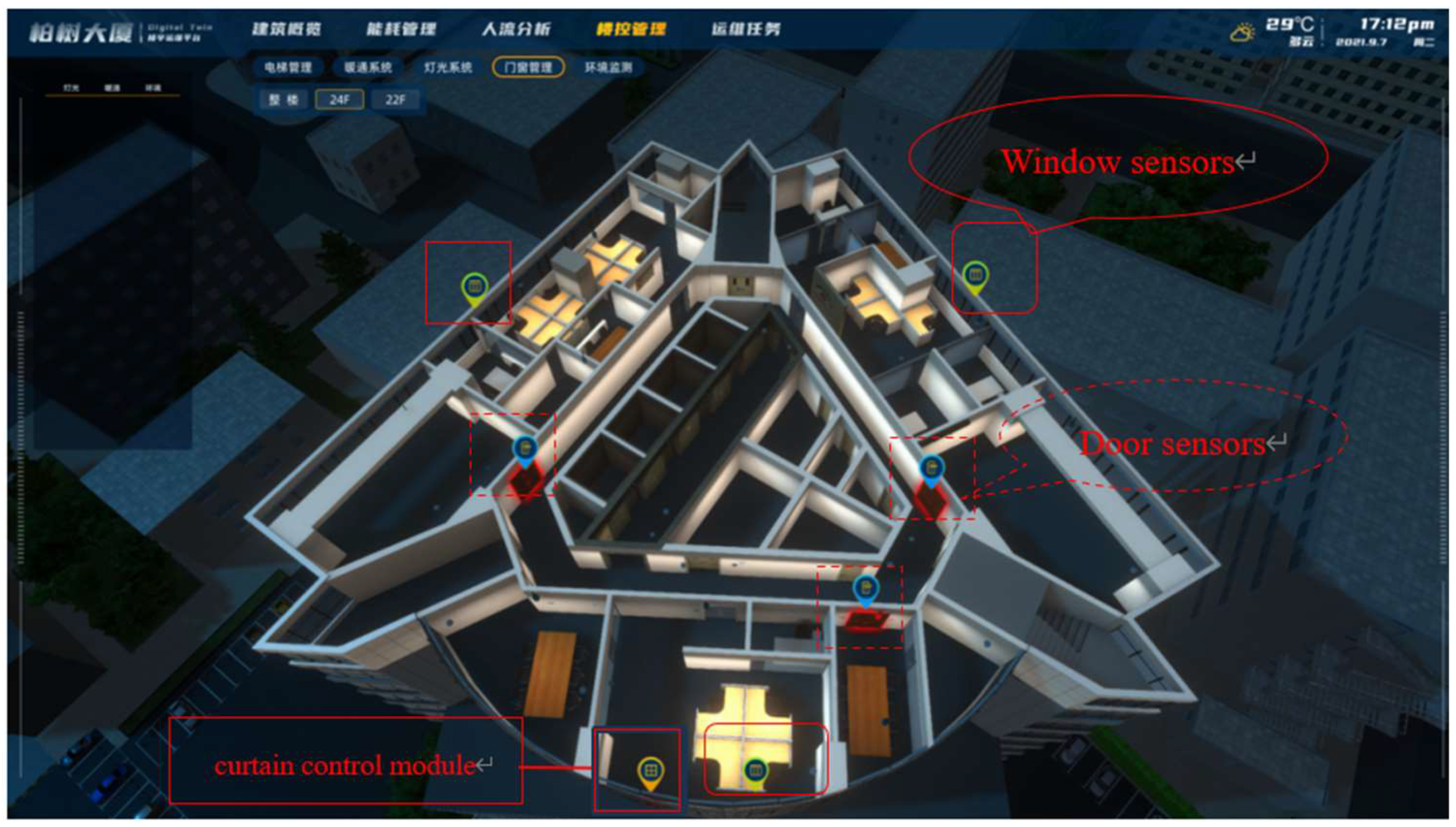
Through the door sensor and curtain control module, the status information of doors, windows, and shading can be monitored. And the doors, windows, and curtains can be controlled. According to the number of windows and doors, there are 18 curtain control modules and 32 door sensors for 22 and 24 floors. Through the building’s digital twin platform, the doors and windows can be remotely controlled, and the curtains can be fully closed, fully opened, and half opened. The control principle of the curtain is based on the illumination of the station and can also be controlled with the lighting. The intelligent door, window, and curtain management interface for the 24th floor is shown in Figure 8.
(4)
Lighting intelligent management system
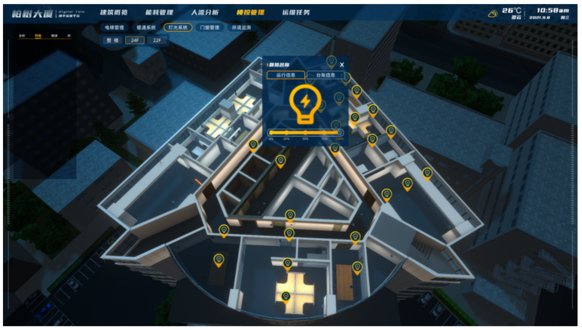
The building of a digital twin platform further improves the lighting system. Public areas and office areas are controlled separately by different strategies. There are 63 sets of lamps on each of the 22 and 24 floors, 0–10 V dimming power LED lighting and 17 sets of infrared sensor detectors. Taking the 24th floor, for example, by setting a remote lighting intelligent control system in the office area and matching the data feedback of the personnel positioning system, the lighting intelligent adjustment function of the server side is realized. The operation of all lighting is controlled according to the personnel situation, and the lamp layout and light brightness can be controlled. The lighting monitoring and intelligent control management interface for the 24 floors is shown in Figure 9.
(5)
HVAC intelligent management system
The building digital twin platform includes the actual size and position of the chiller, fresh air unit, end device, etc., as well as the approximate shape, basic size, and actual position of the main accessories. Sensors are installed at the end of the fan disk and the main pipe of the fresh air system, and they can display energy meter monitoring data (water temperature, flow) and can view the operating status of the chiller unit and the air conditioner end. The air conditioning equipment is controlled by the end energy use, occupants’ behavior, and the indoor and outdoor environment parameters. HVAC intelligent monitoring and control management are shown in Figure 10.
(6)
Building energy consumption monitoring and management
The building energy consumption management interface can display the equipment usage information, the regional energy consumption and the electricity meter alarm for every month, the energy consumption ratio, energy consumption data, and historical energy consumption statistics. Through the smart meter data, the energy consumption data of lighting and HVAC equipment can be viewed in real-time. The building’s energy management interface is shown in Figure 11.
In addition, the elevators in the building are monitored, and the elevator position, status, the number of people currently in the elevator, and the average speed can be viewed through the digital twin platform.

4. Building Energy-Saving Verification for Energy System Monitoring and Management

4.1. Intelligent Control Flow for Building Energy Using

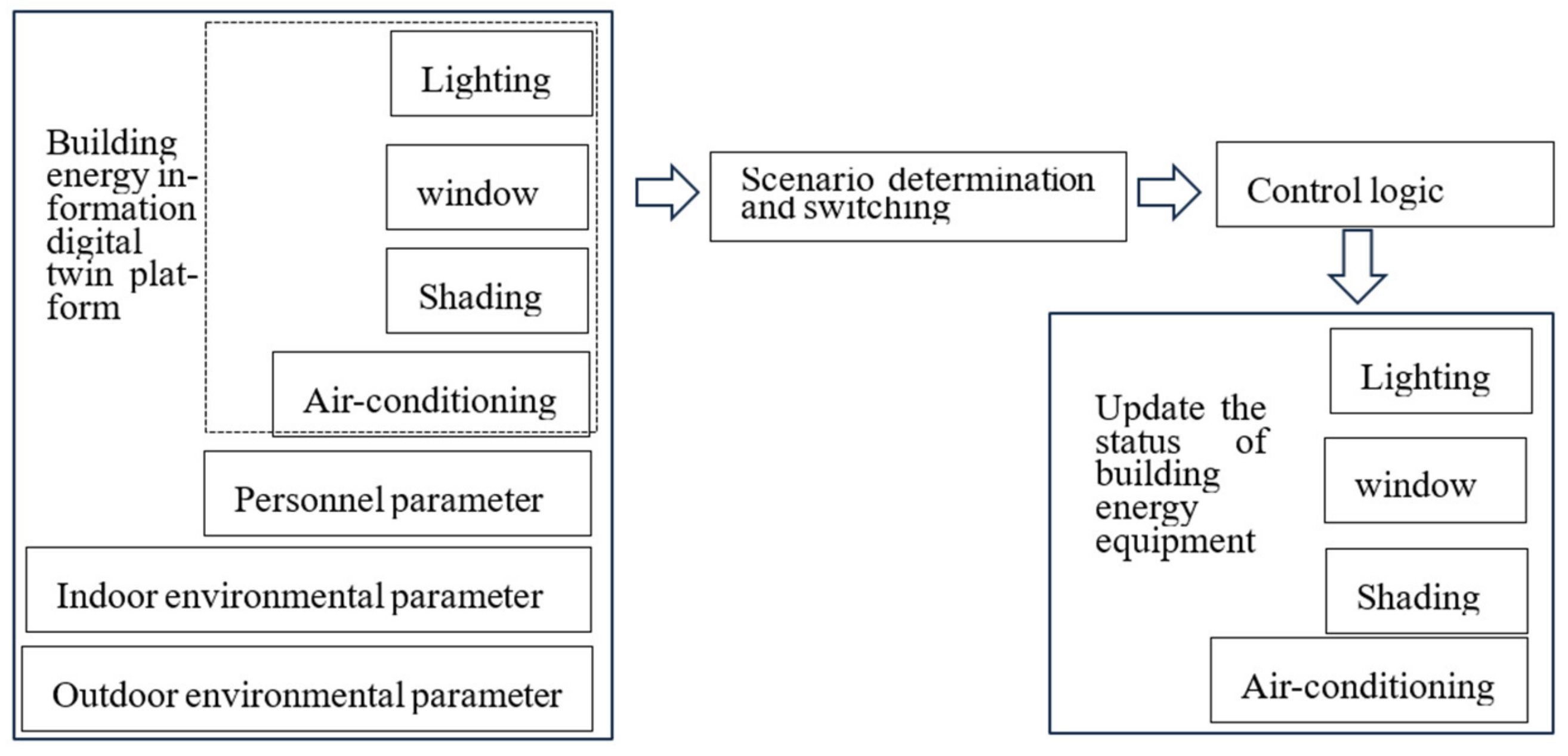
The air conditioning system, lighting system, shading system, and window are the building subsystems which is closely related to the occupants’ behavior. In the operation and maintenance management process of the digital twin platform, the goal is to maximize personnel’s thermal comfort and building energy consumption. The control strategy of a typical situation is developed, and it is realized through the switch of situation combination. The occupants’ usage time and behavior are identified, and the typical situation is summarized. Combined with indoor and outdoor environmental parameters, the air-conditioning load is forecasted, and the fine management of building energy consumption is realized. Intelligent control flow for building energy use is shown in Figure 12.

4.2. Energy-Saving Verification for Building Energy Using Intelligent Control

The demonstration building model was built in Designbuilder software 6.1.2, and a typical scenario was constructed based on occupants’ behavior characteristics. The building energy consumption was simulated, and the subsystem energy consumption was obtained. The simulation of each equipment system includes occupants’ usage time, air conditioning system control, lighting system control, shading control, etc. Through the coupling operation between subsystems, the intelligent control system of the demonstration project is realized. The building energy consumption for using the intelligent control technology was compared and analyzed. The demonstration building model is shown in Figure 13.
(1)
Simulation parameter design
In the simulation, the material composition, thermal parameters of the envelope structure, and interior design parameters were set according to the demonstration building renovation design file, “Shanghai Public Building Energy Saving Design Standard” and “Civil Building Heating Ventilation and Air Conditioning Design Code”. SWERA is used for outside weather. Building envelope structure and thermal parameters are shown in Table 1.
In the simulation, building interior design parameters are shown in Table 2.
Personnel time in the room is the basis for the building energy using intelligent control. Based on the demonstration building investigation, a set of personnel schedules is established. The year is divided into six periods: January and February, March and April, May and June, July and August, September and October, and November and December. The week is divided into weekends and working, for every period has different schedules. The schedule of other equipment in the building is consistent with the personnel schedule.
(2)
Simulation results and analysis for energy consumption
The intelligent control logic of different subsystems is applied to the simulation, and energy-saving results for the air conditioning system applying intelligent control are shown in Table 3.
Energy-saving results for lighting systems applying intelligent control are shown in Table 4.
Energy-saving results for shading systems applying intelligent control are shown in Table 5.
Energy-saving results for all systems applying intelligent control are shown in Table 6.
According to the building energy simulation results, for different equipment systems applying intelligent control, the building energy conservation is different. When the air conditioning system applies intelligent control, summer and winter have better energy-saving. When the lighting system applies intelligent control, the energy consumption is reduced in summer, and the heating energy consumption is slightly increased in winter, but the total building energy consumption is greatly reduced. For the shading system intelligent control application, the building energy-saving is not very obvious. From the overall building energy consumption, multiple sets of intelligent control logic work together to reduce energy consumption by about 31%. It can be seen that building energy consumption can be effectively reduced through intelligent control.

5. Conclusions

Occupants’ behavior has a great influence on air conditioning load. However, the BAS system only realizes equipment switch operation and simple control functions, and it cannot carry out elaborate management. Due to air conditioning load changes, the building energy using an intelligent management platform needs to be improved. It needs to realize the rapid judgment for energy using information, then make a rapid regulatory response, and the operation efficiency will be improved, and building energy consumption will be reduced. The digital twin intelligent control platform can realize occupants’ number and location, energy-using behavior, and environment monitored, read, and judge building equipment information. The simulation engine, air conditioning terminal, lighting, shading, and other equipment will be controlled automatically.
The application effect of the digital twin intelligent control platform is evaluated in the demonstration building. Computer simulation results show that intelligent control based on the personnel number and location, air conditioning, lighting, and shading using scenarios can achieve different degrees of energy saving. Integrated intelligent control for all devices can achieve a building energy maximum saving of 30%. The application of digital twin technology has provided great help for building operation and maintenance management.
The promotion and application of digital twin technology used in new buildings is easy. The reconstruction of the building requires a lot of work. When the virtual platform is built, the BIM model uses 3D Max and Unity 3D technology for visualization and rendering, and a large number of sensors are also needed, so the investment is high. The DTT is not widely used in buildings, just for demonstration only. With the technology development and progress, the cost will be gradually reduced, and the application will be promoted. In addition, the feedback control is based on simulation prediction. Now, with the development of intelligent technology, AI reinforcement learning can be carried out, and it will achieve better energy-saving effects. A lot of research work needs to be performed in the future.

Author Contributions

Conceptualization, C.L.; methodology, P.L.; software, X.Z.; validation, C.L.; formal analysis, H.Z.; data curation, C.L. and W.Z.; writing—original draft preparation, C.L., P.L., H.Z., W.Z. and X.Z.; writing—review and editing, C.L., P.L., X.Z. and H.Z. All authors have read and agreed to the published version of the manuscript.

Funding

This research was funded by the National Natural Science Foundation youth project. Project name, Related Characteristics of Occupants’ Behavior Information and Coordination Regulation Mechanism with Air-conditioning Terminal in Office Buildings. Grant number 52208121, and by 2021 “Science and Technology Innovation Action Plan”, Project name, Research and application of digital technology for low-carbon transformation and energy efficiency improvement in industrial parks. Grant number 21DZ1208400.

Data Availability Statement

Not applicable.

Conflicts of Interest

The authors declare that they have no known competing financial interest or personal relationship that could have appeared to influence the work reported in this paper.

References

  1. Wang, C. Research on Human Behavior Simulation for Building Energy Use. Ph.D. Thesis, Tsinghua University, Beijing, China, November 2014. [Google Scholar]
  2. Tao, F.; Liu, W.; Liu, J.; Liu, X. Exploration of digital twin and its application. Comput. Integr. Manuf. Syst. 2018, 24, 1–18. [Google Scholar]
  3. Zhuang, C.; Liu, J.; Xiong, H.; Xiong, H.; Ding, X.; Ling, S.; Wong, G. The connotation, architecture and development trend of product digital twin. Comput. Integr. Manuf. Syst. 2017, 23, 753–768. [Google Scholar]
  4. Liu, D.; Guo, K.; Wang, B.; Peng, Y. Overview and prospect of digital twin technology. Chin. J. Instrum. 2018, 39, 1–10. [Google Scholar]
  5. White, G.; Zink, A.; Codecá, L.; Clarke, S. A digital twin smart city for citizen feedback. Cities 2021, 110, 103064. [Google Scholar] [CrossRef]
  6. Liu, X.; Wang, J.; Shang, G.; Wu, F.; Zhang, A.; Su, J.; Tang, T. A preliminary study of digital twin technology in spaceport. J. Northwestern Polytech. Univ. 2019, 37, 114–119. [Google Scholar]
  7. Ford, D.N.; Wolf, C.M. Smart Cities with Digital Twin Systems for Disaster Management. J. Manag. Eng. 2020, 36, 04020027. [Google Scholar] [CrossRef]
  8. Boje, C.; Guerriero, A.; Kubicki, S.; Rezgui, Y. Towards a semantic Construction Digital Twin: Directions for future research. Autom. Constr. 2020, 114, 103179. [Google Scholar] [CrossRef]
  9. Ding, K.; Zhang, X.; Zhou, H.; Wang, C.; Yang, H.; Zhang, F.; Cao, X. Multi-dimensional and multi-scale intelligent manufacturing space based on digital twin and its modeling method. Comput. Integr. Manuf. Syst. 2019, 25, 1491–1504. [Google Scholar]
  10. Wang, Y.; Chen, Y.; Wang, W. Design and application of green building operation cost management system based on digital twin. Build. Energy Sav. 2020, 9, 64–70. [Google Scholar]
  11. Hunhevicz, J.J.; Motie, M.; Hall, D.M. Digital building twins and blockchain for performance-based (smart) contracts. Autom. Constr. 2022, 133, 103981. [Google Scholar] [CrossRef]
  12. Angjeliu, G.; Coronelli, D.; Cardani, G. Development of the simulation model for Digital Twin applications in historical masonry buildings: The integration between numerical and experimental reality. Comput. Struct. 2020, 238, 106282. [Google Scholar] [CrossRef]
  13. Lydon, G.P.; Caranovic, S.; Hischier, I.; Schlueter, A. Coupled simulation of thermally active building systems to support a digital twin. Energy Build. 2019, 202, 109298. [Google Scholar] [CrossRef]
  14. Wang, W.; Guo, H.; Li, X. Deep learning for assessment of environmental satisfaction using BIM big data in energy efficient building digital twins. Sustain. Energy Technol. Assess. 2022, 50, 101897. [Google Scholar] [CrossRef]
  15. Zhao, J.; Feng, H.; Chen, Q. Developing a conceptual framework for the application of digital twin technologies to revamp building operation and maintenance processes. J. Build. Eng. 2022, 49, 104028. [Google Scholar] [CrossRef]
  16. He, B.; Wang, F.; Wang, Z. Architectural Digital Twin Application Based on UWB Positioning System. Archit. Techniqu. 2019, 9, 46–48. [Google Scholar]
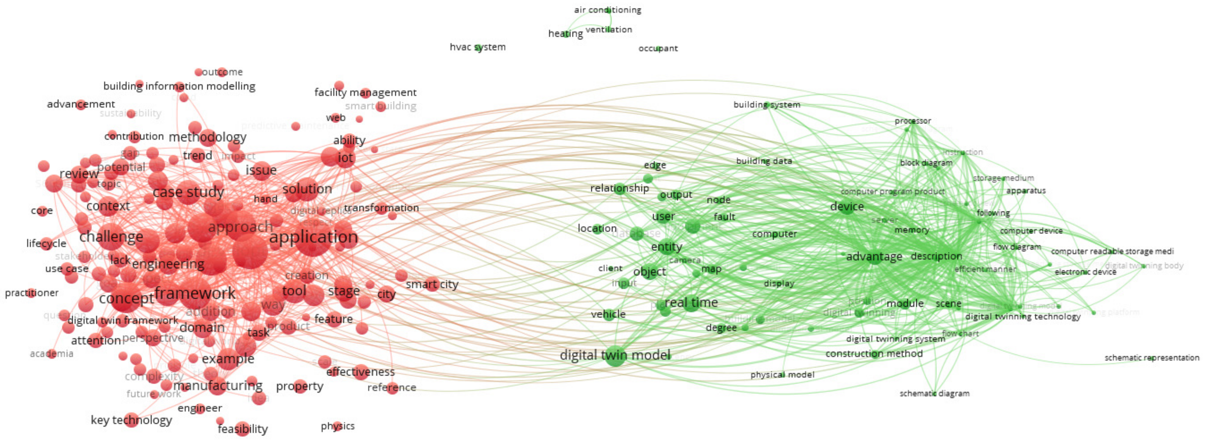
Figure 1. The application status of DTT.
Energies 16 06839 g001
Figure 2. The implementation process of digital twin system for building management.
Energies 16 06839 g002
Figure 3. The building Unity 3D virtual platform flowchart.
Energies 16 06839 g003
Figure 4. Building digital twin operation and maintenance platform interface.
Energies 16 06839 g004
Figure 5. Indoor environment monitoring effect diagram.
Energies 16 06839 g005
Figure 6. Indoor environment and UWB monitoring sensors plane graph for the 24th floor. The red dots are the UWB sensors, and the blue dots are the Environmental monitoring sensors.
Energies 16 06839 g006
Figure 7. Application and implementation of UWB-based personnel location technology. (A) Thermal rendering for personnel performance monitored by UWB. (B). Personnel track diagram.
Energies 16 06839 g007
Figure 8. Door, window, and curtain intelligent management interface for the 24th floor.
Energies 16 06839 g008
Figure 9. The lighting monitoring and intelligent management interface for the 24 floor.
Energies 16 06839 g009
Figure 10. HVAC intelligent management interface. (A) HVAC management interface; (B) Fresh air management interface.
Energies 16 06839 g010
Figure 11. Building energy consumption monitoring and management interface.
Energies 16 06839 g011
Figure 12. Intelligent control flow for building energy use.
Energies 16 06839 g012
Figure 13. The demonstration building model.
Energies 16 06839 g013
Table 1. Building envelope structure and thermal parameters.
BuildingConstituentHeat Transfer CoefficientShading Factor
RoofingCrushed stone concrete (50.0 mm) + Cement mortar (20.0 mm) + Foam glass (70.0 mm) + 1:8 Cement aerated concrete scraps (20.0 mm) + Rebar concrete (120.0 mm)0.68/
Outer wallCement mortar (20.0 mm) + Rock wool tape (40.0 mm) + Cement mortar (20.0 mm) + Porous concrete brick (200.0 mm)1.0/
Exterior windowMetal insulation profile (Height of insulation strip 20 mm) (5 Low-E + 12 A + 5)2.50.4
Table 2. Building interior design parameters.
Functional AreaSummerWinterFresh Air Volume
Office room26 °C2030 m3/h·p
Hall2518/
Table 3. Energy-saving for air conditioning systems applying intelligent control.
Cooling
Energy
Consumption (kWh)
Heating Energy Consumption (kWh)Lighting
Energy
Consumption (kWh)
Equipment Energy
Consumption (kWh)
Total Energy Consumption (kWh)
No intelligent control system3,411,812.331,479,888.041,589,092.85738,846.597,219,639.81
Intelligent control system applications3,180,358.71,211,976.971,589,092.85738,846.596,720,275.11
Energy consumption Comparison−6.78%−18.10%0.00%0.00%−6.92%
Table 4. Energy-saving for lighting systems applying intelligent control.
Cooling
Energy
Consumption (kWh)
Heating
Energy
Consumption (kWh)
Lighting
Energy
Consumption (kWh)
Equipment Energy
Consumption (kWh)
Total Energy Consumption (kWh)
No intelligent control system3,411,812.331,479,888.041,589,092.85738,846.597,219,639.81
Intelligent control system applications2,628,972.131,816,202.4283,331.2738,846.595,467,352.32
Energy consumption Comparison−22.94%22.73%−82.17%0.00%−24.27%
Table 5. Energy-saving for a shading system applying intelligent control.
Cooling
Energy
Consumption (kWh)
Heating
Energy
Consumption (kWh)
Lighting
Energy
Consumption (kWh)
Equipment Energy
Consumption (kWh)
Total Energy Consumption (kWh)
No intelligent control system3,411,812.331,479,888.041,589,092.85738,846.597,219,639.81
Intelligent control system applications3,241,677.31,480,365.731,603,342.22738,846.597,064,231.84
Energy consumption Comparison−4.99%0.03%0.90%0.00%−2.15%
Table 6. Energy-saving for all systems applying intelligent control.
Cooling Energy Consumption (kWh)Heating Energy Consumption (kWh)Lighting Energy Consumption (kWh)Equipment Energy Consumption (kWh)Total Energy Consumption (kWh)
No intelligent control system3,411,812.331,479,888.041,589,092.85738,846.597,219,639.81
Intelligent control system applications2,339,640.751,583,489.31318,117.48738,846.594,980,094.13
Energy consumption Comparison−31.43%7.00%−79.98%0.00%−31.02%
Disclaimer/Publisher’s Note: The statements, opinions and data contained in all publications are solely those of the individual author(s) and contributor(s) and not of MDPI and/or the editor(s). MDPI and/or the editor(s) disclaim responsibility for any injury to people or property resulting from any ideas, methods, instructions or products referred to in the content.