Article

Research on and Assessment of the Reliability of Railway Transport Systems with Induction Motors

1
Department of Electromechanics and Rolling Stock of Railways, Kyiv Institute of Railway Transport of State University of Infrastructure and Technologies, 04071 Kyiv, Ukraine
2
Department of Energy, Faculty of Mechanical Engineering, Technical University of Koszalin, 15-17 Raclawicka St., 75-620 Koszalin, Poland
3
Department of Electrical Engineering, Volodymyr Dahl East Ukrainian National University, 91000 Kyiv, Ukraine
4
Doctoral School, Technical University of Koszalin, 2 Sniadeckich St., 75-620 Koszalin, Poland
5
Faculty of Electronic, Military University of Technology of Warsaw, 2 Urbanowicza St., 00-908 Warsaw, Poland
6
Department of Transport Telecommunication, Faculty of Transport, Warsaw University of Technology, 75 Koszykowa St., 00-662 Warsaw, Poland
7
Faculty of Electronic and Informatics, Technical University of Koszalin, 2 Sniadeckich St., 75-620 Koszalin, Poland
*
Author to whom correspondence should be addressed.
Energies 2023, 16(19), 6888; https://doi.org/10.3390/en16196888
Submission received: 17 July 2023 / Revised: 23 September 2023 / Accepted: 26 September 2023 / Published: 29 September 2023
(This article belongs to the Section F: Electrical Engineering)

Abstract

:
Increasing the efficiency and reliability of modern railway transport is accompanied by an increase in monitoring and diagnostic systems for the current state of electric drives. Modern railway transport contains a large number of induction motors to ensure the operation of the drives of various mechanisms. In the article, based on the operational statistics of engine failures and the proposed scheme for diagnosing them, studies were carried out and a model was developed for assessing the reliability of a transport system equipped with an on-board diagnostic system for the current state. When building the models, the Markov method was used, including the construction of graphs for the five most relevant states of the induction electric motor during operation. The results obtained are relevant for evaluating the effectiveness of using the built-in diagnostic system and scheduling routine maintenance, which will affect the efficiency of railway transport. Based on the process of the diagnosis of railway transport systems with induction motors, five operating states of the object studied were interpreted: the state of full operation, state “S0”; the state of incomplete serviceability, state “S1”; critical serviceability, state “S2”; the state of the pre-damage condition, state “S3”; the state of unserviceability (defect), state “S4”. Subsequently, a five-state model of the operation process of railway transport systems with induction motors was developed. This model is also described by equations of state: Kolmogorov–Chapman equations. The reliability quantities determined form the basis for simulation reliability studies. The effect of the simulation study is the reliability quantities determined in the form of reliability functions and probabilities of the occurrences of the operating states of railway transport systems with induction motors; an important part of the reliability study of the system examined is to estimate the times of the occurrences in the object studied of the operating states in the future.

1. Introduction

In studies on reliability issues, the classical reliability–operational analysis of complex technical objects is applied and can be found in quite a large amount of the significant literature [1,2,3,4,5,6,7,8,9]. In these studies, reliability structures that are possible in practical application are described, including the series, parallel and series–parallel of the technical objects under study. In these studies, it is shown that the knowledge of the reliability structure of complex technical objects makes it possible to make a reliable graphical model of the transitions between the operating states distinguished, along with the specified relationships between them.
In most of the reliability studies analyzed, methods and simulation algorithms for reliability are presented as basic research. These methods are based on the use of Kolmogorov–Chapman equations and Laplace transforms. Practice confirms that this approach is appropriate and makes it possible to calculate the probabilities of staying in the system analyzed in the operating states distinguished.
An interesting and new approach in the reliability conducted by the authors of this article is their studies and research work in this area. They presented new methods for developing models of the exploitation processes of the technical objects under study, including models that were 2-, 3-, 4- and 5-state models. These methods were used with great satisfaction by the authors of the article for reliability and operational analysis in the study of complex technical objects and power supply systems. The results of the research on the operation and design of the models of the operation processes of complex technical objects and electric power systems constitute a fairly large body of research [10,11,12,13,14,15,16].
In the literature analyzed [17], it is shown that a proposal for the use of reserve facilities is presented as an opportunity to increase the reliability of the complex technical objects studied. Such an approach is presented in the work [18]. The research presented here, and the simulations carried out in terms of the power supply reliability, and taking into account economic aspects, confirm the method of applying this type of solution in this category of complex technical facilities.
In the work on the study of the reliability of renewable energy sources, energy storage constitutes an important issue. The energy stored can later be used to power equipment. This, in turn, increases the level of the power supply security. The article [19,20,21,22,23,24,25,26,27,28,29,30,31] describes various technologies and devices for storing energy obtained mainly from renewable energy sources.
The literature [32,33,34,35,36] finds that, in a technical system, the failure of one subsystem in the system can cause the malfunction of the entire complex technical facility or part of the system. For this reason, complex technical objects and information systems are powered from two independent sources. The first power source is the primary power supply, and the second power source is the backup power supply. If the primary power supply fails, then there is an automatic switchover to the backup power supply. In the case of powering information systems, especially in critical-infrastructure facilities (energy, medical, etc.), this may not be sufficient.
In most studies in the literature on reliability [37,38,39,40,41], it is presented that one of the possibilities for assessing the reliability of complex technical facilities is the measurement of time parameters on the actual operation process. Important quantities measured include the average failure-free operation times or average times between failures [42,43,44,45].
In the studies [46,47,48,49,50,51], it is shown that the variability in the failure time of complex technical objects is based, among other things, on the Weibull distribution and is described by a normal distribution function and a probability density function. A new issue in reliability research is the work of Prof. Duer’s team, which generally concerns inverse operation. The research method presented is based on the probabilities determined of the occurrences of the states diagnosed using the reliability characteristics of the object under study; the times of the occurrences in the object of the states recognized in it are estimated.
The novelty of this article in relation to other works of this type lies in the determination of the occurrence times of the possible probabilities of the individual states recognized in the object diagnosed, and especially the determination of the occurrence time of the object’s unserviceability state. This approach offers new opportunities for the construction and development of a new strategy for the restoration of the object under study, which, in this work, is called the strategy according to the occurrence time of the state of unserviceability.

1.1. Motivation and Relevance

The development of transport infrastructure is a priority for each country, as it ensures their level of competitiveness in the world market. The leading place in the implementation of transportation is occupied by rail transport, which is highly economical and second only to sea transport in terms of the cost of freight transportation. Improving the quality and efficiency of transportation by rail helps to accelerate the turnover, reduce the costs associated with the repair and maintenance of transport as well as improve the integrated safety and reliability during operation, which is especially important for passenger transportation. One of the main ways to improve the reliability and efficiency of transport operation is to ensure the required level of reliability of its main technical units and elements. Modern railway transport contains a large number of induction motors to ensure the operation of the drives of various mechanisms. Induction motors with squirrel-cage rotors are the most widely used due to their relatively high reliability, low cost and ease of maintenance. In railway transport, induction motors are used both as traction drives for electric locomotives and to ensure the operability of various auxiliary devices and mechanisms as fan motors and motor compressors for feed pumps, ventilation systems, refrigerators, etc.
However, given the complexity of the operating conditions of railway transport electric drives, many malfunctions can occur, leading to emergency equipment failures. The peculiarity of the operation of induction motors for different devices and mechanisms of transport systems lies in the complex effect of a number of physical factors, such as a sharply changing load mode, vibromechanical effects, including those from working mechanisms, high and low temperatures, pressure drops, high humidity, etc. According to the average operational statistics of electric locomotive equipment failures [52,53], the distribution of which is shown in Figure 1, the largest share of failures falls on electric motors and makes up almost half of all electric locomotive equipment failures during their operation.
From the above statistics of failures, it follows that the reliability of railway transport depends on the reliable operation of the induction motors and, therefore, the most productive way to increase the operational efficiency is to maintain their operable and serviceable condition during operation. To prevent the occurrence of malfunctions and failures of railway transport equipment, a system of preventive maintenance and current repairs has been created, which should ensure a high coefficient of the technical readiness of railway rolling stock and its uninterrupted and trouble-free operation in accordance with the production logistics schedule.
However, scheduled maintenance and repairs do not fully identify damages at the initial stages of their development and do not prevent possible emergency equipment failures due to defects that have arisen and progress in the course of operational impacts. According to the industry statistics available, up to 20% of electrical machines are subject to replacement, without any possibility of recovery, which is caused by the untimely detection of defects and the appearance of secondary damage during the period of intensive operation. To ensure the necessary control of the technical condition of the main elements of the electric drive, it is necessary to widely introduce and use built-in diagnostic monitoring systems in real time. In addition, the diagnostic system, apart from detecting a defect, must also differentiate the degree of damage, which increases the accuracy of predicting the period of the no-failure operation of the electric motor for planning the time to eliminate it.
Currently, researchers and manufacturers of transport equipment are paying the most active attention to improving diagnostic systems and implementing an effective technical monitoring program during operation, which ensures the detection of incipient malfunctions at the earliest stages. Modern types of diagnostic equipment make it possible to automate the detection of damage and the adoption of the necessary decisions when assessing technical systems directly during operation. The active implementation and use of diagnostic built-in systems for monitoring the state of electric drives will increase the reliability and efficiency of railway transport operation [54].
An assessment of the advantages of using diagnostic systems and increasing the accuracy of assessing reliability parameters should be carried out when formalizing modeling and calculating reliability parameters, taking into account the properties of the object under consideration. In addition, simulation models of the real processes of the functioning of specific technical systems form the basis for studying and obtaining data from simulation models of the process in order to develop effective service concepts and improve their reliability.

1.2. Literature Review

Ensuring the efficient and reliable operation of railway transport equipment is associated with the solutions to a whole range of particular tasks that take into account the specifics and operating conditions of various components of transport equipment. Such tasks arise at different stages and in various forms in the process of planning the quality work of railway transport. To develop the concept of the reliable operation and maintenance strategy for railway transport equipment, mathematical modeling methods are widely used, which employ the basic laws of the theory of the probability of random events and the calculation of reliability indicators. A wide range of various tasks to be solved to improve the efficiency of railway transport operation using simulation is presented in a number of works by modern researchers. In [55], a mathematical model for making decisions on planning maintenance activities for a given period was developed within the framework of the normal maintenance operations of railway rolling stock during the period of operation. Improved reliability-based modeling is used to develop new and more flexible maintenance strategies that improve the reliability and availability of light rail vehicles during the operation phase, as well as reduce its life-cycle cost, as discussed in [56]. In [57], using modeling, the issue of scheduling the movement of railway rolling stock is solved, taking into account the schedule of maintenance and repair work with a limited number of rolling-stock units. The issues of choosing a rolling-stock maintenance strategy, the evaluation of spare parts and the calculation of the replacement interval of its components using mathematical models are considered in [58,59,60]. In [61,62,63], the authors use models to assess the reliability of the railway system and improve the accuracy of the failure prediction to plan the optimal time for maintenance activities. The models developed and the methodologies used are characterized by a different approach to solving problems and are based on the mathematical methods of the Markov theory, the Poisson theory, the Monte Carlo modeling approach, the Bayesian theory and the analysis of failure modes and effects using the Taylor series or hybrid models [64,65,66,67,68]. The work [69] presents a study of equipment reliability based on analytical models using dependencies of reliability on the example of Wind Farm Equipment.
When compiling a mathematical model, an important task is to establish input parameters to obtain correct results. In [70,71,72], the logistic fault tree method is used to set the necessary input parameters.
Increasing requirements for the reliability of railway transport have led to the development of the theory of reliability with the solutions to problems by taking into account the performance and functional safety of the technical objects of transport throughout the life cycle. The modeling of dynamic stable processes for studying the efficiency of a transport object is considered in [73,74]. To compile effective probabilistic mathematical models in [75,76,77], methods of mathematical statistics for analyzing the operation of diesel engines and generalized failure criteria are used. Given that the operation of railway transport is always associated with various kinds of risks, risk assessment methods are effectively used in the development of models for planning maintenance, as well as in the design and operation [78,79]. Some technical systems of railway transport are characterized by the presence of several internal states that experience degradation processes during operation. Models for such systems are considered both multilevel and with a continuous process of degradation of several elements subject to various influences during operation, and these are effectively described by the semi-Markov process [80,81,82,83].
From our point of view, research on modeling various tasks of operation and improving the reliability of railway transport is more focused on regulating production and the rhythm of traffic during the planning period for maintenance and repair, while the coordination of the maintenance and repair of rolling stock equipped with modern control systems and the state of its main elements are still under study. To ensure the competitiveness of railway transport, maintenance strategies and improving the accuracy of reliability assessments are becoming more relevant and important tasks to address as a matter of priority.
The originality of the work is the research and development of a model for assessing the reliability of railway transport with asynchronous electric motors using the built-in on-board diagnostic system for monitoring the condition of its main elements, taking into account the specifics of their failures.

1.3. Organization of the Paper

The article is structured as follows: Section 2 analyzes the vulnerability of the main components of the induction motor and the structure of a diagnostic system for monitoring the motor’s condition. Section 3 presents the state model of the induction motor during operation. Section 4 presents a five-state model of the operation process of railroad transportation systems with induction motors. Section 5 covers an analysis and evaluation of the reliability of the process of the operation of railroad transportation systems with induction motors, and Section 6 and Section 7 present a discussion of the results obtained and conclusions.

2. Diagnostic System as Part of the Electric Drive of Railway Transport

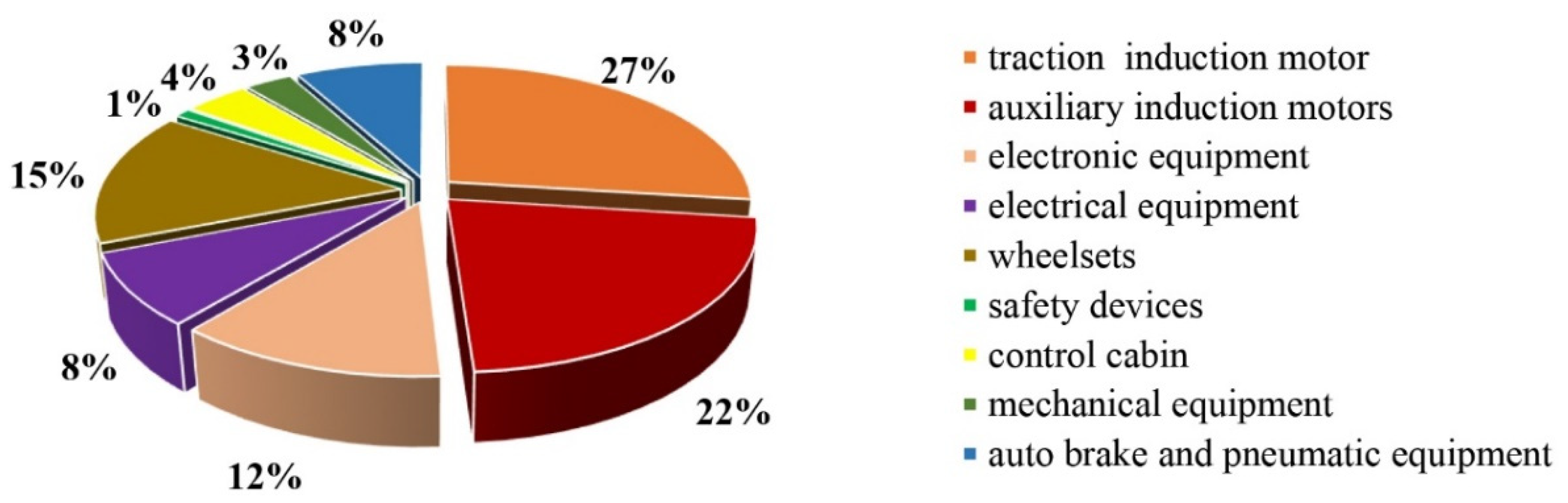
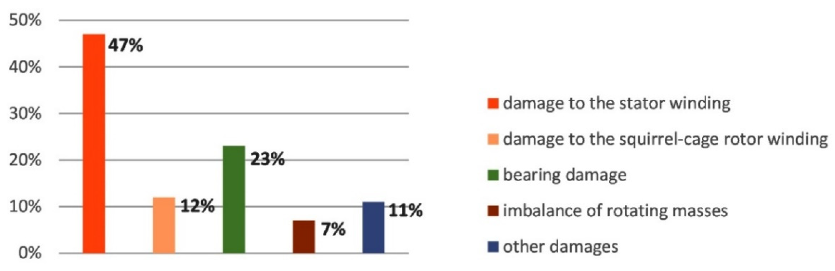
2.1. Damage Analysis of Induction Motors during Operation

To compile a diagnostic system for an electric drive, it is necessary to analyze the damage to the motor taking into account the design features of the induction motor. The main structural elements of a squirrel-cage induction motor include the stator, rotor and bearing assembly. Depending on the design, functions performed by the engine and operating conditions, the distribution of the failures for these elements may differ, but the general principle remains the same. The average results of the failures of induction motors with squirrel-cage rotors according to operational statistics [84,85,86] are presented in the failure diagram in Figure 2.
The main element of the engine damaged during operation is the stator. The most significant damage to the stator includes a turn-to-turn short circuit in the stator winding, breakdown to the housing, interphase short circuit, weakening of the package pressing or stator-fastening elements and stator eccentricity or ellipse. Winding-to-case breakdown and phase-to-phase faults lead to the sudden catastrophic failure of the motor, which is impossible to foresee. Turn-to-turn short circuits in the winding constitute the most common defect in induction motors and, according to statistics, account for up to 75% of all stator failures. This type of damage occurs as a result of frequent overloads and overheating with deterioration in the insulating properties of the winding. Depending on the number of closed turns, the engine can continue to operate with deterioration in its performance and energy characteristics [87,88]. However, this type of defect tends to develop during the period of continued operation, and this leads to a sudden emergency stop, resulting in a complication of engine recovery. The remaining stator defects are not critical for affecting the engine performance and must be eliminated during the next maintenance period.
The next important structural element of the engine, which its performance depends on, is the rotor. The main damage to the rotor includes damage to the structure of the squirrel-cage winding, eccentricity of the outer surface, twisting of the shaft, imbalance of the rotor core or the fan impeller and defective couplings. If the contact is damaged or the integrity of several rods of the squirrel-cage rotor is broken, then the engine continues to be in working condition with deterioration in the parameters. With further work, an increased current occurs on the remaining winding rods and, at increased loads, the remaining rotor rods begin to melt, which leads to an emergency engine failure. In addition, in some cases, damaged rods are displaced by centrifugal force towards the air gap outside the rotor core. This leads to the contact of the damaged rods with the surface of the core or stator winding, resulting in accidents with substantial damage that must be repaired. In all cases, a motor with a damaged squirrel-cage rotor winding, when operating under load, consumes increased current from the network, does not reach the operating speed of rotation, is accompanied by increased vibration and overheats more than a serviceable motor [89]. Motor shaft twisting is a catastrophic accident with an abrupt failure that cannot be foreseen.
Monitoring the condition of the bearing units of electric motors is the most important and responsible task, which not only ensures the operability of an electric machine, but also affects the condition of its main structural elements: the stator and the rotor. The most typical types of the failure of the bearing assemblies of electric motors are the mechanical wear of the seating surfaces of bearing shields, bodies and raceways as a result of impact loads or large static loads without rotation, the destruction of the outer or inner ring due to a mismatch between the load conditions of the bearings on the shaft and increased abrasion and wear during the loss of lubricant properties.
When defects occur in the operation of bearings, vibration occurs due to the appearance of radial or axial clearance. In addition to the destructive effect of vibration on all the structural elements of the machine, the destruction of the bearing creates a misalignment of the axis of the rotation of the rotor, in which, given the small size of the air gap, the rotating active steel of the rotor touches the active steel of the stator core [90]. Further operation of the engine with such a defect leads to a complete failure of the machine in an emergency mode without any possibility of recovery.
The unbalance of the rotating masses of the rotor is one of the most common defects in the equipment, leading to a sharp increase in vibration. Vibration from unbalance in many cases is dangerous not only because of its amplitude, but also because it is an excitatory factor for many structural elements, which leads to the “manifestation” of signs of other defects in the condition of the equipment. The causes of unbalance in equipment can be of different natures: they can be the result of many design features, defects in manufacturing or installation, or those that appeared during operation. The unbalance of the engine design is subject to elimination at the engine installation site in the presence of balancing devices and is not critical for its operation in the case of timely detection.
From the analysis of the types of damage to the induction motor, it follows that it is necessary to present in the diagnostic system the blocks for monitoring the state of each structural element of the engine, including the unbalance of the rotating masses [91]. Engine damage and defects have an electrical or mechanical nature of manifestation; therefore, to ensure high-quality diagnostics, it is necessary to use blocks in a single block diagram with different methods for their detection.

2.2. Principles of the Construction and Structure of the Diagnostic System for Monitoring the Technical Condition of the Engine

To build a block diagram of the diagnostic system, one should take into account the frequent types of defects in each structural element of the induction motor, which can develop during operation and need to be monitored in real time. This will make it possible to control the growth of the degree of damage to prevent the occurrence of secondary failures and emergency stops.
These types of damage include turn-to-turn short circuits of the stator winding and the destruction of the winding rods of the squirrel-cage rotor and bearing wear [92,93]. It is not justifiable to consider in the diagnostic system defects that occur due to extreme impacts or emergency loads and lead to sudden catastrophic failures that cannot be foreseen. In addition, there are a number of defects and damages to the main elements of the engine design of a non-critical nature, accompanied mainly by the appearance of additional vibration spectra. Such defects in the diagnostic system will only be ascertained without conducting qualitative and quantitative analyses of their causes, and these are combined into a common group of “other defects”.
Taking into account the above principles of construction, Figure 3 shows a block scheme of a diagnostic built-in system for monitoring induction motors in railway transport.
For the operation of the diagnostic system, it is necessary to provide each monitoring unit with the necessary signals, taking into account the diagnostic method used. Thermal [94], current [91] or vibration [95] diagnostic methods are the most widespread, and they are used in diagnostic systems for detecting, identifying and differentiating engine damage. To detect electrical damage, methods based on an analysis of the values of the motor stator phase currents have received the greatest application and compliance with modern requirements for diagnostic systems [96].
Thus, refs. [97,98] present studies on the application of the Park’s vector hodograph method for diagnosing turn-to-turn short circuits in the stator winding and damage to the rotor-winding rods. The principle of the method is to convert the obtained stator phase currents from a three-phase coordinate system into a moving two-phase system (dq-coordinates). Fault detection using the Park’s vector consists in an analysis of the trajectory (hodograph) described by the end of the vector, along which the diagnostic features corresponding to various faults are determined. The Park vector for a healthy engine describes a regular circle centered at the origin. In the presence of damage, the figure described by the Park’s vector differs from the ideal circle in accordance with the type of destruction in shape, thickness, etc. The change in the shape of the Park vector pattern is differentiated by mathematical relations, and the type and degree of damage is established from them [99,100].
The application of the Park’s vector method is the most effective for diagnosing inter-turn short circuits in the stator winding and damage to the rotor-winding rods as part of the on-board diagnostic system. According to a number of studies, the Park’s vector method makes it possible to obtain reliable results on the number of closed turns in the stator winding or the number of damaged rods of the rotor winding when the engine is running under load in dynamic and static modes (i.e., directly during operation). In addition, the main feature of this method is the possibility of obtaining reliable diagnostic results in the presence of asymmetric or non-sinusoidal voltage systems, which are utilized in railway transport systems.
To carry out diagnostics using this method, three current sensors and three voltage sensors, and one sensor of the angular speed of the rotation of the rotor (the “sensor system” from Figure 3), are used. Current and voltage sensors are installed one by one on each phase of the motor directly on the terminal box or on the power supply control panel to monitor the state of both the stator winding and the rotor winding via the values of the phase currents and phase voltages. The monitoring of the presence of inter-turn short circuits in one or more phases of the winding stator organized in this way makes it possible to determine the damaged phase and the number of closed turns under the static and dynamic loads of the electric motor, regardless of the quality of the supply voltage. Using the same sensors, the state of the rotor is simultaneously monitored with the determination of the number of damaged rods during the operation of the engine. The numbers of detected closed turns in the stator winding and damaged rods in the rotor winding are displayed on the block of the display system (Figure 3). Determining the degree of damage to the stator winding and rotor winding allows one to predict the time of trouble-free operation and to plan the repair of the transport equipment.
To monitor the condition of the bearings and bearing assemblies, two vibration sensors are used, which are installed inside the engine one by one on the end shields at the location of the bearings. The vibrational picture of the unbalance of rotating masses is manifested simultaneously on two bearings of the controlled mechanism; therefore, the same sensors are used to control and debug the rotating elements with the detection of diagnostic spectra. Excess vibration parameters are transmitted to the indexing unit to control the development of the corresponding damage or defect.
When vibration spectra that are uncertain for determining the type of damage are detected, which can occur in the presence of various defects during the operation of the engine, it is informatively signaled to the display unit as “other defects”, to be taken into account during the next maintenance or repair of the engine.
The structure considered of the diagnostic system was proposed during the course of research by Dr. Gubarevych O. and is ready for implementation in a physical form for use in production conditions.

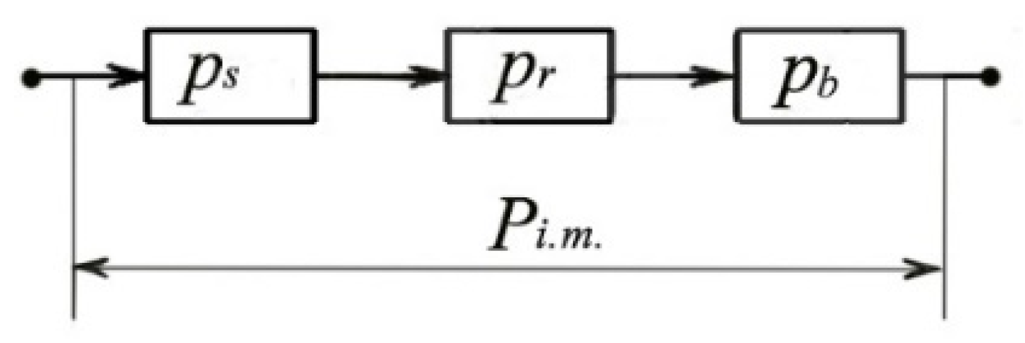
3. Structural Scheme of the Reliability of Induction Motors during Operation

The experience of using diagnostic systems indicates an increase in the reliability of technical systems and an increase in the efficiency of their operation. To obtain a quantitative assessment of the reliability of the operation of railway transport with induction motors, it is necessary to use modeling methods. An important step in modeling the process of the operation of such a technical system is the development of a model for the process of restoring the system and scheduling maintenance, taking into account the diagnostic system. For planning the operation and maintenance of railway transport, a partial reliability assessment is used, which is not systemic in nature and does not have a comprehensive approach. Therefore, the development and implementation by transport enterprises of a formalized system for a comprehensive assessment of the reliability of the railway transport operation process, which takes into account all the stages of the transportation process, is a relevant and important issue.
Evaluation of the reliability indicators of the transportation process, solving optimization problems related to maintaining and restoring the operability of the production system for providing rail transportation requires the use of a mathematical theory of reliability.
Reliability is understood as the property of a system to perform specified functions over a certain time interval and, at the same time, to maintain the values of established production characteristics within specified limits under appropriate conditions of operation, repair, storage and transportation.
As discussed above, the reliable operation of railway transport largely depends on the reliability of induction motors, which ensure its performance. The reliability of the induction motor (Pi.m.) is determined by the reliability of its structural elements: the stator, rotor and bearing assembly. The failure of one of the listed elements leads to the failure of the entire engine, so the reliability scheme is presented as a series connection of the reliability of the elements: stator (ps), rotor (pr) and bearing assembly (pb), as shown in Figure 4.
Then, the reliability of the induction motor is determined from the following relationship:
P i . m . = p s · p r · p b = i = 1 n p i
Reliability indicators are divided into two groups characterizing non-recoverable (stator winding, rotor winding and bearings) and recoverable (stator, rotor, bearing unit, electric motor) elements. For the recoverable elements, which include the electric motor, in addition to the widely used quantitative characteristics of reliability, the main indicators of reliability include the probability of failure-free operation over a period of time (P(t)), the failure rate (λ(t)) and the complex criterion—coefficient of readiness (Kr).
Failures of these elements can be functional or parametric in nature. The failure of the operation leads to the fact that the engine goes into a state in which it cannot perform the functions assigned to it (that is, an emergency-type failure). Such failures are of a sudden (catastrophic) nature as a result of electrical or mechanical factors, more often as a result of external influences during engine operation that exceed the capabilities of the structural elements and cannot be foreseen. Parametric failures (turn-to-turn short circuits, contact failures in the short-circuited rotor winding, increased bearing radial clearance) disrupt the performance of the motor, without leading to an emergency stop, but with the prospect of developing secondary failures and an emergency stop. Such specificity of the failures of the elements of induction motors is taken into account when building a model.

4. Five-State Model of Operation Process of Railway Transport Systems with Induction Motors

The process of the operation of railway transport systems with induction motors, similar to any complex technical object, consists of a random sequence of alternating states of use and operation. A five-state model of the operation process was adopted for reliability studies: the state of full operation, state “S0”; the state of an incomplete serviceability, state “S1”; a critical serviceability, state “S2”, the state of pre-damage condition, state „S3”; the state of unserviceability (defect), state “S4”.
1. The operational state, state “S0”: This state corresponds to the nominal mode of the operation of the engine in the continuous mode. However, during the course of operation, deviations in the operating modes accumulate with overheating in excess of the temperature margin of the windings and operation under conditions of increased vibrations or temperature, frequent starts and an increased load. Even short-term excesses of the normalized parameters established by the technical conditions lead to the appearance of initial defects in the main structural elements, which subsequently tend to develop and lead to a disruption in the operable state: a catastrophic or parametric failure. This leads to a decrease in the working-capacity margin during continuous operation (service life);
2. The state of an incomplete serviceability, state “S1”. Turn-to-turn short circuits in the stator winding (initial damage to the stator winding) (faulty operational state (parametric stator failure)). From the beginning of the motor operation, the stator winding is subjected to operating heating up to the nominal temperature corresponding to the heat resistance class of the insulation. When several turns are closed in a winding phase, the current in this phase increases, which is accompanied by additional heating in the damaged phase. In addition, an asymmetrical magnetic field of the stator is created, which causes the rotor to vibrate during rotation. The increased current in the stator phase affects the current increases in the rotor bars. At the same time, the motor continues to operate with a deterioration in its energy and performance indicators (power consumption increases, efficiency decreases, etc.). An elevated temperature accelerates the development of damage to the winding insulation due to a violation of its temperature regime and leads to secondary failures. Vibration also contributes to the destructive effect on the windings (the processes of abrasion and insulation punching). Vibration affects the bearings and contributes to the violation of their seats and structural clearances, which leads to a subsequent failure of the bearings;
3. Critical serviceability, state “S2”. Increased bearing vibration (initial bearing failure) (faulty operational state) (parametric bearing failure). From the very beginning of operation, bearings are subject to a constant process of friction and wear. If the bearings fail during engine operation, then increased vibrations and increased heat occur. Vibration in bearings has a detrimental effect on the stator winding and rotor winding, affecting their wear rate. In addition, the temperature increase in the damaged bearings affects the heating temperature inside the motor and the processes of thermal disturbance inside the machine, contributing to the acceleration of the aging of the stator winding and its failure (breakdown). Bearings with increased clearance must be replaced;
4. The state of the pre-damage condition, state ”S3”. Violation of the integrity of the rotor-winding rods (deterioration in the contact in the rotor bars) (fault, operating condition) (parametric rotor failure). During the normal operation of the rotor structure, in the presence of hidden defects that were not detected during the running-in period or under the influence of increased vibrations and temperature, contacts may be broken in the short-circuited design of the rotor winding, which is accompanied by the appearance of additional vibrations and an increase in the current in the remaining rods and heating. This is an operable state with accumulated parametric deviations with a limited operability margin. Further destruction of the rods (burnout) can occur during the continued operation or during the emergency operation of the rotor with a significant increase in the currents in the rotor. Increased heating during operation affects the thermal balance inside the motor and leads to the accelerated aging of the stator winding and its failure. Vibration also has a destructive effect on both the stator winding and bearings. If the welded structure of the rotor winding is damaged, then the rods are replaced and soldered to short-circuit rings. In the case of a cast winding, it must be completely replaced. The rotor is a renewable element of the engine design;
5. The state of unserviceability (defect), state “S4”. Combined crash (disabled state, stator and rotor catastrophic failure). With an increase in the load mode with an increased concentration of electrical and mechanical stresses, a current accident is possible with a simultaneous failure of the stator winding and the rotor winding. Current accidents associated with the breakage of conductors in the stator or rotor windings, interturn and phase-to-phase short circuits of the windings, broken contacts and the destruction of joints made by soldering or welding lead to an insulation breakdown as a result of heating caused by the flow of overload or short-circuit currents. A breakdown or flashover of the stator-winding insulation can lead to a short circuit, which is the most dangerous type of emergency operation. An emergency mode of this type is characterized by an increase in the current value by tens and even hundreds of times compared to the current in the normal mode, which poses a threat to other engine elements.
The model of the operation process of railway transport systems with induction motors is shown in Figure 5 as a set of operating states with the following interpretation:
-
S0—state of serviceability;
-
S1—state of incomplete serviceability;
-
S2—state of critical serviceability;
-
S3—state of pre-damage serviceability;
-
S4—state of unserviceability.
Figure 5 shows the graph of the operation process of the facility. This graph (Figure 5) is a simplified way of representing the form of the object operation process. In the graph, its vertices are distinguished; they denote the states. In turn, the arcs connecting the vertices of the graph define the relations–transitions between the states. The graph of the exploitation process developed in this way is used to develop it in another analytical form, mainly in the form of equations of state: Kolmogorov-Chapman equations. In particular, in Figure 5, the following transitions between the distinguished states are shown graphically across the arcs:
-
λ (S0, S1); hence, λ has an interpretation of the intensity of the transition of the system from state S0 to state S1;
-
μ (S1, S0); hence, μ has an interpretation of the intensity of the transition of the system from state S1 to state S0;
-
λ (S0, S2); hence, λ1 has an interpretation of the intensity of the system’s transition from state S0 to state S2;
-
μ (S2, S0); hence, μ1 has an interpretation of the intensity of the system’s transition from state S2 to state S0;
-
λ (S2, S3); hence, λ2 has an interpretation of the intensity of the system’s transition from state S2 to state S3;
-
μ (S3, S0); hence, μ2 has the interpretation of the intensity of the transition of the system from state S3 to state S0;
-
λ (S2, S4); hence, λ3 has an interpretation of the intensity of the system’s transition from state S2 to state S4;
-
μ (S4, S0); hence, μ3 has an interpretation of the intensity of the system’s transition from state S4 to state S0.
Figure 5. Model of operation process of railway transport systems with induction motors (source: authors’ own elaboration).
Energies 16 06888 g005
Designations in Figure 5:
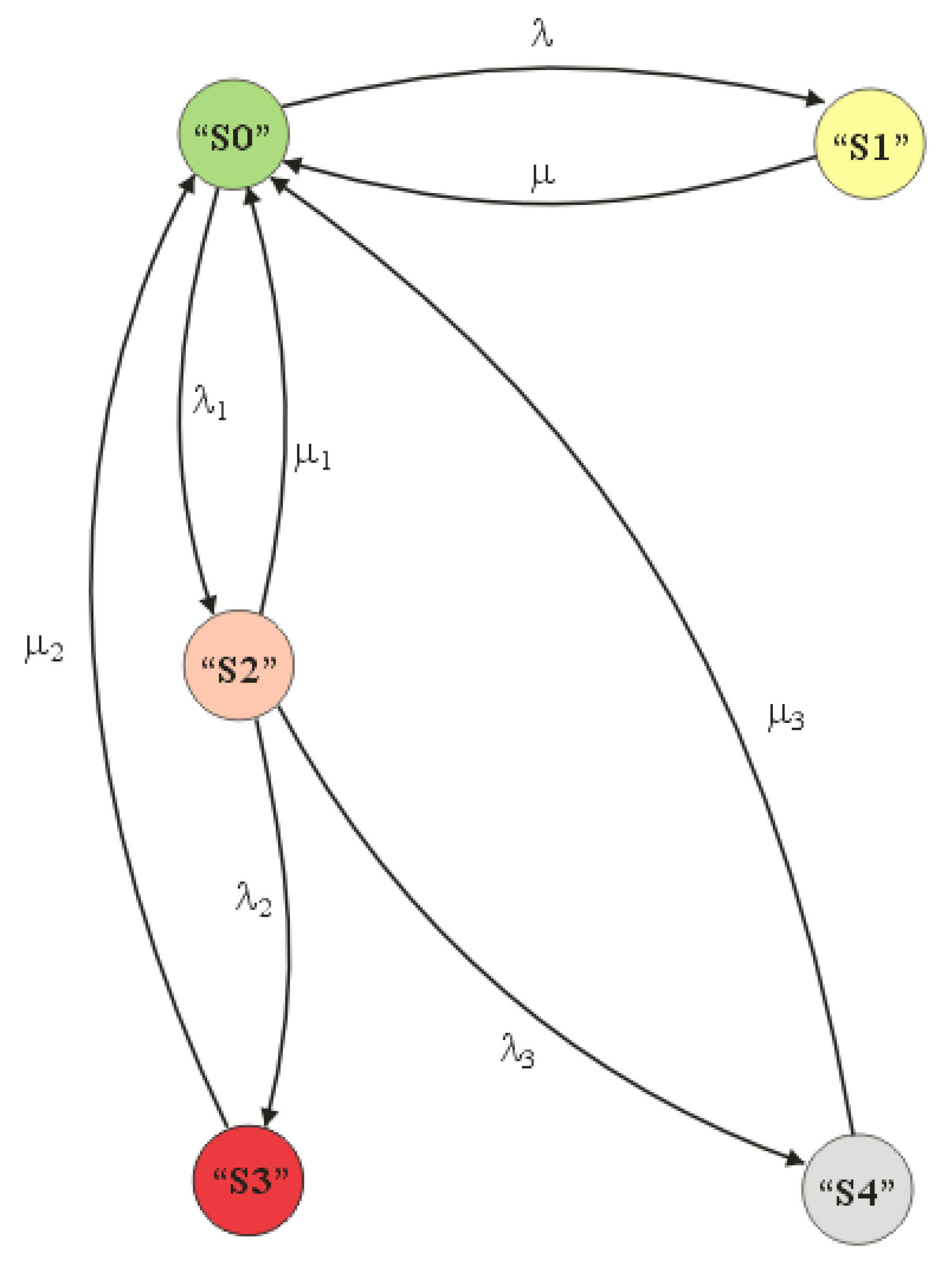
  • λ—intensity of the system transition from S0 state to S1 state;
  • μ—transitions of the system from S1 state to S0 state;
  • λ1—intensity of the transition of the system from state S0 to state S2;
  • μ1—system transitions from state S2 to state S0;
  • λ2—intensity of system transitions from state S2 to state S3;
  • μ2—system transitions from state S3 to state S0;
  • λ3—intensity of system transitions from state S2 to state S4;
  • μ3—transitions of the system from state S4 to state S0.
In the literature, different ways and approaches are used in reliability research to represent the operation process model of a technical object. Most often in research practice, the model of the exploitation process of any technical object is presented in a graphical form. The graphical form of the realization of the object’s operation process is the process graph. Another possible way of representing the realization of the object’s operation process is its analytical form. The right approach in reliability research in this regard is one in which the mentioned forms of the models of the object’s operation process, and therefore the graphical and analytical forms, occur together and complement each other.
If it is assumed that the modeling of the exploitation process consists in determining the probabilities of railway transport systems with induction motors remaining in individual states {S0, S1, S2, S3, S4}, then it is necessary to determine the following:
-
The function of the probability of the system remaining in state S0;
-
The function of the probability of the system being in state S1;
-
The function of the probability of the system being in state S2;
-
The function of the probability of the system being in state S3;
-
The residence probability function of the system in state S4.

5. Analysis and Evaluation of the Reliability of the Operation Process of Railway Transport Systems with Induction Motors

To determine the probabilities of the residence of railway transport systems with induction motors in particular states of interest, the transition network shown in Figure 6 should be described using the following equations:
λ · P 0 + μ · P 1 λ 1 · P 0 + μ 1 · P 2 + μ 2 · P 3 + μ 3 · P 4 = 0 λ · P 0 μ · P 1 = 0 λ 1 · P 2 λ 2 · P 2 μ 1 · P 2 + λ 1 · P 0 = 0 λ 2 · P 2 μ 2 · P 3 = 0 λ 3 · P 3 μ 3 · P 4 = 0
In a matrix notation, this can be represented as follows:
[ ( λ + λ 2 ) λ λ 1 0 0 μ μ 0 0 0 μ 1 0 ( λ 2 + λ 3 + λ 1 ) λ 2 λ 3 μ 2 0 0 μ 2 0 μ 3 0 0 0 μ 3 ] · [ P 0 P 1 P 2 P 3 P 4 ] = [ 0 0 0 0 0 ]
By transforming it, we obtain the following:
P 1 = λ μ · P 0 P 2 = λ 2 λ 1 + λ 2 + μ 1 · P 0 P 3 = λ 2 μ 2 · P 2 P 4 = λ 3 μ 3 · P 2
Obviously enough,
P 0 + P 1 + P 2 + P 3 + P 4 = 1
Thus,
P 0 · ( 1 + λ μ + λ 2 λ 2 + λ 3 + μ 1 + λ 2 μ 2 · λ 1 λ 2 + λ 3 + μ 1 + λ 3 μ 3 · λ 1 λ 2 + λ 3 + μ 1 ) = 1
P 0 = 1 ( 1 + λ μ + λ 2 λ 2 + λ 3 + μ 1 + λ 2 μ 2 · λ 1 λ 2 + λ 3 + μ 1 + λ 3 μ 3 · λ 1 λ 2 + λ 3 + μ 1 )
P 0 = μ · μ 2 · μ 3 · ( λ 2 + λ 3 + μ 1 ) μ · μ 2 · μ 3 · ( λ 2 + λ 3 + μ 1 ) + λ · μ 2 · μ 3 · ( λ 2 + λ 3 + μ 1 ) + μ · μ 2 · μ 3 · λ 1 + μ · μ 3 · λ 2 · λ 1 + μ · μ 2 · λ 3 · λ 1
Figure 6. Graph of changes in the probability of railway transport systems with induction motors remaining in a fully serviceable state (S0) for a period of 1 year (source: authors’ own elaboration).
Energies 16 06888 g006

6. Research Results

In the simulation study, Expression (8) was used, on the basis of which it was possible to determine the magnitude studied of the probability of the transport of railway transport systems with induction motors remaining in the serviceability state. The magnitude of the probability of the serviceability for the use of any technical object in reliability is called the reliability function ( P 0 ( t ) ). Numerically, for a given value of time, it is equal to the value of the readiness index.
Computer simulations made it possible to quickly determine the impact of changes in the various reliability and operational indicators on the values of the indicators describing the states of the diagnostic system analyzed. In the analysis, the system repair and damage intensities shown in Table 1 were adopted. The values adopted were calculated on the basis of literature data and operational data obtained from railroad power companies.
Taking Equations (4)–(8), using the inverse Laplace transform and the values in Table 1, we obtain the following probabilities of the system tested remaining in each operating state for an exponential distribution:
-
The duration of the test system of railway transport systems with induction motors—1 year:
t = 8760 (h)
-
The probability of railway transport systems with induction motors remaining in a fully serviceable state (S0) for a period of 1 year:
P 0 ( t ) = 0.9988319222061706
-
The probability of railway transport systems with induction motors remaining in a state of partial serviceability (S1) for a period of 1 year:
P 1 ( t ) = 0.00047974
-
The probability of railway transport systems with induction motors remaining in a state of critical serviceability (S2) for a period of 1 year:
P 2 ( t ) = 0.000480149
-
The probability of railway transport systems with induction motors remaining in pre-damage condition (S3) for 1 year:
P 3 ( t ) = 0.00019985
-
The probability of the railway transport systems with induction motors tested remaining in an unfit state (S4) for 1 year:
P 4 ( t ) = 8.32 × 10 6 = 0.00000832
The purpose of the reliability studies conducted on the railway transport system with induction motors was, firstly, to determine the probability of this system being in a state of use. The second objective was to determine the times of the occurrences of the reliability states distinguished. This research approach is a new method of research on the problem of studying the reliability of a complex technical object, such as railway transport systems with induction motors. For this purpose, the incapability function (P0(t)) was determined for the object under study and the adopted test time. Then, the values of the probabilities of the occurrences of the recognized states in the railway transport systems with the induction motors studied were determined based on the characteristics of the P0(t). The probability values determined for the states recognized unambiguously determined their respective time intervals on the P0(t) characteristics (Figure 6).
The problem of determining the times of the occurrence of the probability of a given recognized state in diagnostics requires the plotting of the detailed characteristics of the P0(t). From the analysis of the characteristic (P0(t)) in Figure 6, it can be seen that the values determined of the probabilities calculated of the distinguished set of states in 5 VL logic {S1, S2, S3, S4} are located in the lower part of the characteristic P0(t) in Figure 6 Thus, the characteristic (P0(t)), with a range of changes in its values below 0.001, is presented for further study (Figure 7).
Figure 7 shows the estimated values of the probabilities of the designated states of the object. The points that are the probabilities of the occurrences of the states (Pi(t)) are marked on the P0(t) characteristic. The time intervals estimated (P0(t)) on the plot of the (P0(t)) (Figure 7) of the corresponding probabilities of the occurrence of each state are as follows:
  • P0 = 0.99883 → 〈0 ÷ 5500〉 [h]
  • P1 = 0.0004801 → 〈5500 ÷ 6000〉 [h]
  • P2 = 0.0004797 → 〈6000 ÷ 7000〉 [h]
  • P3 = 0.000199 → 〈7000 ÷ 8000〉 [h]
  • P4 = 8.32593 × 10⁻⁶ → 〈 t > 8000〉 [h]

7. Discussion

In the simulation studies carried out for the reliability assessment of railway transport systems with induction motors, the reliability function (P0(t)) was used, the graphs of which are shown in Figure 6 and Figure 7. From the analysis of the P0(t) characteristics and the posted values of the probabilities ((Pi(t))) of the occurrence of possible states during the studied time of the use of railway transport systems with induction motors, the following conclusions are drawn:
  • The time T1, which signifies the occurrence of the S0 state—the state of fitness—has the value (T1 = 5500 [h]). Thus, in the time interval < 0; 5500 [h] > the object under test object is in a fully functional S0 state;
  • The time T2, which denotes the occurrence of the S1 state—the state of incomplete fitness—has the value (T2 = 6000 [h]). Thus, in the time interval < 5500 [h]; 6000 [h] > the object under study is in the S1 state—the state of incomplete fitness. In this state, rail transportation systems with induction motors perform their tasks with a violation of the technical characteristics;
  • The time T3, which denotes the occurrence of state S2—the state of critical fitness— has the value (T3 = 7000 [h]). In the time interval < 6000 [h]; 7000 [h] > the object under study is in state S2—the state of critical fitness. In the S2 state, rail transport systems with induction motors under testing perform their tasks with a minimum load;
  • The next tested time is T4, which denotes the occurrence of state S3—the pre-damage state—which has a value of (T4 = 8000 [h]). Thus, in the time interval < 7000 [h]; 8000 [h] > the tested object is in the S3 state—the pre-damage state. In the S3 state, the tested rail transportation systems with induction motors perform their tasks to a minimum extent;
  • In the time interval above < 8000 [h] > the tested object is in the state S4—the state of inoperability. In this state, the rail transportation system with induction motors ceases to perform its tasks and breaks down.
In the process of the operation of the technical object shown in Figure 7, external conditions affect it, as do the internal conditions acting on the technical object, which, with progressive aging processes, cause damage to occur in it. Damage occurring to a technical object can be of a minor or very significant nature. All damages adversely affect its further use. Based on the literature, damage occurring in a technical object can be presented as follows:
  • Damage is a condition occurring in a technical object in which there is a loss of the ability of the object to perform its required functions (the object ceases to carry out its tasks). Damage by its nature can be divided into critical and non-critical;
  • Critical (sudden) damage is damage that causes a state of unserviceability in the technical object—the “0” state. In this state, there is a sudden total loss in the object’s ability to perform its required functions. Critical damage can entail significant property damage or other dangerous events for the facility itself and the personnel operating the facility;
  • Non-critical (parametric) damage is damage that occurs gradually in a technical facility during its use as a result of aging changes, the effects of internal factors (e.g., temperature, pressure, etc.) occurring in the structural elements of the facility, etc.
In a technical object during its use, there is a condition in which there is a gradual (parametric) continuous decrease in the level of the operational characteristics. There is also a gradual parametric decline in the ability of the object to perform its required functions. Non-critical damage does not necessarily entail any material loss or other dangerous events for the facility itself or the personnel operating the facility.
The simulation study conducted on the reliability assessment of railway transport systems with induction motors made it possible to determine important operational information for the user of this object—when to start the implementation of the renewal process of this object. The study made it possible to determine the times (T3 and T4) of the occurrences in the object of states S3 and S4 denoting the pre-damage and unserviceable states. The knowledge of the T3 and T4 times may provide basic operational information in the object studied for an implementation of renewal. Knowledge of this information can be used to plan the timing of the optimal renewal of this facility. The method proposed has been verified in practice, and it is a major achievement of the authors to develop a renewal strategy for complex technical objects, which has been named the “Renewal strategy for complex technical objects according to time T4—the time of the occurrence of an unfit state”.

8. Conclusions

The article presents the problem of the reliability testing of railway transport systems with induction motors. The basis of the research carried out was the development of a diagnostic system for the object under study (Figure 3). On the basis of the diagnosis of railway transport systems with induction motors, five operating states of the object studied were interpreted. Further, a five-state model of the operation process of railway transport systems with induction motors was developed. This model was also described with equations of state: Kolmogorov–Chapman equations. On this basis, reliability quantities were determined for which simulation studies will be carried out.
The novelty of this article in relation to other such works lies in the development of a method for determining the times of the occurrences of the possible probabilities of the various states, especially the states of unserviceability. Determining the time of the occurrence of an object’s state of unserviceability offers new opportunities for developing a new strategy for the restoration of the object under study. In the simulation studies conducted on the reliability assessment of railway transport systems with induction motors, relevant operating information was obtained in the form of times T3 and T4, the times of the occurrences in the object of states S3 and S4 denoting the state of critical serviceability and the state of unserviceability. Following the literature, we may conclude that the knowledge of the T2 and T3 times may form the basic operational information in the object studied, which can be used to plan the timing of the optimal renewal of this object. Thus, a major achievement of the authors is the development of a strategy for the renewal of complex technical objects, which is called the “Strategy for renewal of complex technical objects according to time T4—the time of the occurrence of an unfit state”.

Author Contributions

Conceptualization, O.G. and S.D.; methodology, software, validation, formal analysis, O.G., I.M., M.W., D.B. and K.Z.; investigation, K.R.; resources, J.P.; data curation, O.G. and M.S.; writing—original draft preparation, I.M. and K.Z.; writing—review and editing, I.M. and J.P.; visualization, M.W.; authors’ supervision, O.G. and S.D.; project administration, funding acquisition, S.D. All authors have read and agreed to the published version of the manuscript.

Funding

This research received no external funding.

Data Availability Statement

The data presented in this article are available upon request from the corresponding authors.

Conflicts of Interest

The authors declare no conflict of interest.

Abbreviations

AEnvironmental and Ambient
BGrid
CBrake Systems
DHydraulics
EYaw System
FCommunications
GConnectors
HProtection Relays
IPitch System
JCooling and Heating Systems
KTransmission
LMV Unit Power Transformer
MController
NGearbox
OGenerator
PRotor
QFeeder Cable Line Field
RShunt Reactor Field
SPower Transformer Field
TAuxiliaries Field
UVoltage Measurement Field
WGeneral Signalization

References

  1. Epstein, B.; Weissman, I. Mathematical Models for Systems Reliability; CRC Press: Boca Raton, FL, USA; Taylor & Francis Group: Abingdon, UK, 2008. [Google Scholar]
  2. Jin, T. Reliability Engineering and Service; John Wiley & Sons: Hoboken, NJ, USA, 2019. [Google Scholar]
  3. Verma, A.K.; Ajit, S.; Karanki, D.R. Reliability and Safety Engineering; Springer: London, UK, 2010. [Google Scholar] [CrossRef]
  4. Kołowrocki, K.; Soszyńska-Budny, J. Reliability and Safety of Complex Technical Systems and Processes; Springer: London, UK, 2011. [Google Scholar]
  5. Stawowy, M.; Rosiński, A.; Paś, J. Klimczak. Method of Estimating Uncertainty as a Way to Evaluate Continuity Quality of Power Supply in Hospital Devices. Energies 2021, 14, 486. [Google Scholar] [CrossRef]
  6. Stawowy, M.; Rosiński, A.; Siergiejczyk, M.; Perlicki, K. Quality and Reliability-Exploitation Modeling of Power Supply Systems. Energies 2021, 14, 2727. [Google Scholar] [CrossRef]
  7. Sozański, J. Niezawodność i Jakość Pracy Systemu Elektroenergetycznego; WNT: Warszawa, Poland, 1990. [Google Scholar]
  8. Xiong, F.; Ji, X.; Wei, D.; Li, G. Reliability Assessment of Micro Grid Power Supply System Based on D-Vine Copula Model. In Advanced Manufacturing and Automation X. IWAMA 2020, Lecture Notes in Electrical Engineering; Springer: Singapore, 2021; Volume 737. [Google Scholar] [CrossRef]
  9. Duer, S. Assessment of the Operation Process of Wind Power Plant’s Equipment with the Use of an Artificial Neural Network. Energies 2020, 13, 2437. [Google Scholar] [CrossRef]
  10. Duer, S. Applications of an artificial intelligence for servicing of a technical object. Neural Comput. Appl. 2013, 22, 955–968. [Google Scholar] [CrossRef]
  11. Duer, S. Expert knowledge base to support the maintenance of a radar system. Def. Sci. J. 2010, 60, 531–540. [Google Scholar] [CrossRef]
  12. Duer, S. Artificial Neural Network-based technique for operation process control of a technical object. Def. Sci. J. 2009, 59, 305–313. [Google Scholar] [CrossRef]
  13. Duer, S. Diagnostic system for the diagnosis of a reparable technical object, with the use of an artificial neural network of RBF type. Neural Comput. Appl. 2010, 19, 691–700. [Google Scholar] [CrossRef]
  14. Stawowy, M. Identifying status of an ICT system using rough sets. Arch. Transp. Syst. Telemat. 2014, 7, 50–53. [Google Scholar]
  15. Stawowy, M.; Kasprzyk, Z. Identifying and simulation of status of an ICT system using rough sets. In Theory and Engineering of Complex Systems and Dependability. DepCoS-RELCOMEX 2015. Advances in Intelligent Systems and Computing; Springer International Publishing: Berlin/Heidelberg, Germany, 2015; Volume 365. [Google Scholar] [CrossRef]
  16. Kalpana, S.; Saranya, N.; Saundariya, K. An IoT Based Real-Time Monitoring and Controlling of Sub-Station Equipment. In Proceedings of the 2021 International Conference on System, Computation, Automation and Networking (ICSCAN), Puducherry, India, 30–31 July 2021. [Google Scholar] [CrossRef]
  17. Zhu, Q.; Xu, S.; Sun, J.; Li, X.; Zhou, D. Energy efficiency evaluation of power supply system: A data-driven approach based on shared resources. Appl. Energy 2022, 312, 118683. [Google Scholar] [CrossRef]
  18. Wu, X.; Zhao, W.; Wang, X.; Li, H. An MILP-Based Planning Model of a Photovoltaic/Diesel/Battery Stand-Alone Microgrid Considering the Reliability. IEEE Trans. Smart Grid 2021, 12, 3809–3818. [Google Scholar] [CrossRef]
  19. Wang, Y.; Nie, L.; Dang, Y.; Deng, G.; Li, J.; Li, P.; Wang, P.; Luo, H.; Qin, Z.; Chen, S. Fault Prediction of Power Electronic Devices in Mobile UPS System. In Proceedings of the 2021 IEEE 16th Conference on Industrial Electronics and Applications (ICIEA), Online, 1–4 August 2021. [Google Scholar] [CrossRef]
  20. BLobov, N.; Kolpakhch’yan, P.G.; Belokopytov, S.A.; Madzhid, A.D.R.A. A choice of the structure of the photovoltaic system for power supply. Russ. Electr. Eng. 2015, 86, 398–402. [Google Scholar] [CrossRef]
  21. Mahmoud, M.S.; AL-Sunni, F.M. Control and Optimization of Distributed Generation Systems; Springer International Publishing: Berlin/Heidelberg, Germany, 2015. [Google Scholar] [CrossRef]
  22. Azaza, M.; Eriksson, D.; Wallin, F. A study on the viability of an on-site combined heat- and power supply system with and without electricity storage for office building. Energy Convers. Manag. 2020, 213, 112807. [Google Scholar] [CrossRef]
  23. Liu, J.; Chen, X.; Cao, S.; Yang, H. Overview on hybrid solar photovoltaic-electrical energy storage technologies for power supply to buildings. Energy Convers. Manag. 2019, 187, 103–121. [Google Scholar] [CrossRef]
  24. Banik, R.; Das, P. A Review on Architecture, Performance and Reliability of Hybrid Power System. J. Inst. Eng. Ser. B 2020, 101, 527–539. [Google Scholar] [CrossRef]
  25. Wang, L. (Ed.) Modeling and Control of Sustainable Power Systems; Springer: Berlin, Germany, 2012. [Google Scholar] [CrossRef]
  26. Krzykowski, M.; Krzykowska, K. Will the European Commission’s policy hinder gas supplies to Central and Eastern European countries? OPAL case decision. Energy Policy 2017, 110, 534–541. [Google Scholar] [CrossRef]
  27. Nagaraja, Y.; Kumar, M.V.; Raju, T.D. Analysis and design of a robust controller for a grid-connected photovoltaic power plant. Int. J. Ambient. Energy 2018, 41, 326–333. [Google Scholar] [CrossRef]
  28. Jahid, A.; Monju, K.H.; Hossain, S.; Hossain, F. Hybrid power supply solutions for off-grid green wireless networks. Int. J. Green Energy 2019, 16, 12–33. [Google Scholar] [CrossRef]
  29. Li, Y.; Ren, X.; Niu, J. Application of rough sets theory in forecast of power generation for grid-connected photovoltaic system. In Proceedings of the 27th Chinese Control and Decision Conference (2015 CCDC), Qingdao, China, 23–25 May 2015. [Google Scholar] [CrossRef]
  30. Duer, S.; Valicek, J.; Paś, J.; Stawowy, M.; Bernatowicz, D.; Duer, R.; Walczak, M. Neural Networks in the Diagnostics Process of Low-Power Solar Plant Devices. Energies 2021, 14, 2719. [Google Scholar] [CrossRef]
  31. Ghorani, R.; Fattaheian-Dehkordi, S.; Farrokhi, M.; Fotuhi-Firuzabad, M.; Lehtonen, M. Modeling and Quantification of Power System Resilience to Natural Hazards: A Case of Landslide. IEEE Access 2021, 9, 80300–80309. [Google Scholar] [CrossRef]
  32. Keyhani, A.; Marwali, M. Smart Power Grids; Springer: Berlin/Heidelberg, Germany, 2011. [Google Scholar] [CrossRef]
  33. Stasiuk, O.I.; Grishchuk, R.V.; Goncharova, L.L. Mathematical differential models and methods for assessing the cybersecurity of intelligent computer networks for control of technological processes of railway power supply. Cybern. Syst. Anal. 2018, 54, 671–677. [Google Scholar] [CrossRef]
  34. Kozyra, J.; Łukasik, Z.; Kuśmińska-Fijałkowska, A.; Kaszuba, P. The impact of selected variants of remote control on power supply reliability indexes of distribution networks. Electr. Eng. 2021, 104, 1255–1264. [Google Scholar] [CrossRef]
  35. Zhou, K.; Wei, S.; Yang, S. Time-of-use pricing model based on power supply chain for user-side microgrid. Appl. Energy 2019, 248, 35–43. [Google Scholar] [CrossRef]
  36. Paś, J.; Siergiejczyk, M. Interference impact on the electronic safety system with a parallel structure. Diagnostyka 2016, 17. No 1. [Google Scholar]
  37. Gao, D.; Li, G.; Yu, J. Does digitization improve green total factor energy efficiency? Evidence from Chinese 213 cities. Energy 2022, 247, 123395. [Google Scholar] [CrossRef]
  38. Liu, X.; Nielsen, P.S. A hybrid ICT-solution for smart meter data analytics. Energy 2016, 115, 1710–1722. [Google Scholar] [CrossRef]
  39. Paś, J.; Rosiński, A. Selected issues regarding the reliability-operational assessment of electronic transport systems with regard to electromagnetic interference. Eksploat. Niezawodn. Maint. Reliab. 2017, 19, 375–381. [Google Scholar] [CrossRef]
  40. He, Y.; Liang, X.D.; Deng, F.M.; Li, Z. Emergency Supply Chain Management Based on Rough Set—House of Quality. Int. J. Autom. Comput. 2019, 16, 297–309. [Google Scholar] [CrossRef]
  41. Xie, H.; Hu, X.; Peng, Z.; Yao, X.; Chen, Y. A Method of Electricity Consumption Behavior Analysis Based on Rough Set Fuzzy Clustering. In Proceedings of the 2nd IEEE Conference on Energy Internet and Energy System Integration (EI2), Beijing, China, 20–22 October 2018. [Google Scholar] [CrossRef]
  42. Changhua, H. Distribution Network Fault Location Based on Rough Set and Data Fusion. In Proceedings of the 2019 IEEE 4th Advanced Information Technology, Electronic and Automation Control Conference (IAEAC), Chengdu China, 20–22 December 2019. [Google Scholar] [CrossRef]
  43. Liu, X.; Zhao, X.; Jin, P.; Lu, T. Optimization Strategy for New Energy Consumption Based on Intuitionistic Fuzzy Rough Set Theory. In Proceedings of the 39th Chinese Control Conference (CCC), Shenyang, China, 27–29 July 2020. [Google Scholar] [CrossRef]
  44. Siergiejczyk, M.; Stawowy, M. Modelling of uncertainty for continuity quality of power supply. In Proceedings of the Risk, Reliability and Safety: Innovating Theory and Practice; CRC Press/Balkema: London, UK, 2017. [Google Scholar]
  45. Dai, Q.; Shi, L.; Ni, Y. Risk Assessment for Cyberattack in Active Distribution Systems Considering the Role of Feeder Automation. IEEE Trans. Power Syst. 2019, 34, 3230–3240. [Google Scholar] [CrossRef]
  46. Fuhg, J.N.; Böhm, C.; Bouklas, N.; Fau, A.; Wriggers, P.; Marino, M. Model-data-driven constitutive responses: Application to a multiscale computational framework. Int. J. Eng. Sci. 2022, 167, 103522. [Google Scholar] [CrossRef]
  47. Pawlak, Z. Rough Sets—A New Mathematical Method of Data Analysis. Institute of Theoretical and Applied Informatics, Polish Academy of Sciences, Warsaw, Poland, 1995. [Google Scholar]
  48. Stawowy, M.; Targosiński, T. The use of rough set to estimate the quality of objects recognition and localization. In Risk, Reliability and Safety: Innovating Theory and Practice: Proceedings of ESREL 2016; CRC Press/Balkema: Boca Raton, FL, USA, 2016. [Google Scholar]
  49. Li, H.; Chen, M.; Yang, B.; Blaabjerg, F.; Xu, D. Fast Fault Protection Based on Direction of Fault Current for the High-Surety Power-Supply System. IEEE Trans. Power Electron. 2018, 34, 5787–5802. [Google Scholar] [CrossRef]
  50. Pawlak, Z. Rough Sets; Institute of Computer Science, Polish Academy of Sciences: Warsaw, Poland, 1981. [Google Scholar]
  51. Wiatr, J.; Miegoń, M. UPS Power Supplies and Accumulator Batteries in Emergency Power Systems; MEDIUM Publishing House: Warsaw, Poland, 2008. [Google Scholar]
  52. Puzyr, V.; Datsun, Y.; Obozny, O.; Pyvo, V. Development of a repair technology for locomotive units on the basis of the theory of decision. IOP Conf. Ser. Mater. Sci. Eng. 2019, 664, 012029. [Google Scholar] [CrossRef]
  53. Goolak, S.; Liubarskyi, B.; Lukoševičius, V.; Keršys, R.; Keršys, A. Operational Diagnostics System for Asymmetric Emergency Modes in Traction Drives with Direct Torque Control. Appl. Sci. 2023, 13, 5457. [Google Scholar] [CrossRef]
  54. Hoelzl, C.; Dertimanis, V.; Landgraf, M.; Ancu, L.; Zurkirchen, M.; Chatzi, E. Chapter 9—On-board monitoring for smart assessment of railway infrastructure: A systematic review. In The Rise of Smart Cities: Advanced Structural Sensing and Monitoring Systems; Butterworth-Heinemann: Oxford, UK, 2019; pp. 223–259. ISBN 9780128177846. [Google Scholar] [CrossRef]
  55. Mira, L.; Andrade, A.R.; Gomes, M.C. Maintenance scheduling within rolling stock planning in railway operations under uncertain maintenance durations. J. Rail Transp. Plan. Manag. 2020, 14, 100177. [Google Scholar] [CrossRef]
  56. Erguido, A.; Márquez, A.C.; Castellano, E.; Flores, J.L.; Fernández, J.F.G. Reliability-based advanced maintenance modelling to enhance rolling stock manufacturers’ objectives. Comput. Ind. Eng. 2020, 144, 106436. [Google Scholar] [CrossRef]
  57. Giacco, G.L.; Carillo, D.; D’Ariano, A.; Pacciarelli, D.; Marín, Á.G. Short-term Rail Rolling Stock Rostering and Maintenance Scheduling. Transp. Res. Procedia 2014, 3, 651–659. [Google Scholar] [CrossRef]
  58. Cheng, Y.-H.; Tsao, H.-L. Rolling stock maintenance strategy selection, spares parts’ estimation, and replacements’ interval calculation. Int. J. Prod. Econ. 2010, 128, 404–412. [Google Scholar] [CrossRef]
  59. Huynh, K.T.; Castro, I.T.; Barros, A.; Bérenguer, C. Modeling age-based maintenance strategies with minimal repairs for systems subject to competing failure modes due to degradation and shocks. Eur. J. Oper. Res. 2012, 218, 140–151. [Google Scholar] [CrossRef]
  60. Marseguerra, M.; Zio, E. Optimizing maintenance and repair policies via a combination of genetic algorithms and Monte Carlo simulation. Reliab. Eng. Syst. Saf. 2000, 68, 69–83. [Google Scholar] [CrossRef]
  61. De Simone, L.; Caputo, E.; Cinque, M.; Galli, A.; Moscato, V.; Russo, S.; Cesaro, G.; Criscuolo, V.; Giannini, G. LSTM-based failure prediction for railway rolling stock equipment. Expert Syst. Appl. 2023, 222, 119767. [Google Scholar] [CrossRef]
  62. Nazarizadeh, F.; Alemtabriz, A.; Zandieh, M. An analytical model for reliability assessment of the rail system considering dependent failures (case study of Iranian railway). Reliab. Eng. Syst. Saf. 2022, 227, 108725. [Google Scholar] [CrossRef]
  63. Sun, Y.; Ma, L.; Mathew, J.; Zhang, S. An analytical model for interactive failures. Reliab. Eng. Syst. Saf. 2006, 91, 495–504. [Google Scholar] [CrossRef]
  64. Duer, S.; Paś, J.; Hapka, A.; Duer, R.; Ostrowski, A.; Woźniak, M. Assessment of the Reliability of Wind Farm Devices in the Operation. Energies 2022, 15, 3860. [Google Scholar] [CrossRef]
  65. Cacchiani, V.; Huisman, D.; Kidd, M.; Kroon, L.; Toth, P.; Veelenturf, L.; Wagenaar, J. An overview of recovery models and algorithms for real-time railway rescheduling. Transp. Res. Part B Methodol. 2014, 63, 15–37. [Google Scholar] [CrossRef]
  66. Percy, D.F.; Khairy, A.; Kobbacy, H.; Fawzi, B. Setting preventive maintenance schedules when data are sparse. Int. J. Prod. Econ. 1997, 51, 223–234. [Google Scholar] [CrossRef]
  67. Corman, F.; Trivella, A.; Keyvan-Ekbatani, M. Stochastic process in railway traffic flow: Models, methods and implications. Transp. Res. Part C Emerg. Technol. 2021, 128, 103167. [Google Scholar] [CrossRef]
  68. Luo, J.; Wen, C.; Peng, Q.; Qin, Y.; Huang, P. Forecasting the effect of traffic control strategies in railway systems: A hybrid machine learning method. Phys. A Stat. Mech. Its Appl. 2023, 621, 128793. [Google Scholar] [CrossRef]
  69. Duer, S.; Zajkowski, K.; Harničárová, M.; Charun, H.; Bernatowicz, D. Examination of Multivalent Diagnoses Developed by a Diagnostic Program with an Artificial Neural Network for Devices in the Electric Hybrid Power Supply System “House on Water. Energies 2021, 14, 2153. [Google Scholar] [CrossRef]
  70. Pokoradi, L. Logical Tree of Mathematical Modeling. Theory Appl. Math. Comput. Sci. 2015, 5, 20–28. [Google Scholar]
  71. Brancevich, P.; Li, Y. Model of the Decision-Making System for Assessment of the State of Technical Objects. In Proceedings of the 28th International Congress on Sound and Vibration, Singapore, 24–28 July 2022. [Google Scholar]
  72. Shcherbovskykh, S.; Stefanovych, T.; Denysyuk, P. Reliability Analysis of the Duplicated Wired Channels with Tripled Protective Reinforcement. In Proceedings of the 2022 IEEE XVIII International Conference on the Perspective Technologies and Methods in MEMS Design (MEMSTECH), Zakarpattia Oblast, Ukraine, 7–11 September 2022; pp. 89–92. [Google Scholar] [CrossRef]
  73. Bondarenko, I.; Severino, A.; Olayode, I.O.; Campisi, T.T.; Neduzha, L. Dynamic Sustainable Processes Simulation to Study Transport Object Efficiency. Infrastructures 2022, 7, 124. [Google Scholar] [CrossRef]
  74. Lovska, A.; Fomin, O.; Pistek, V.; Kucera, P. Dynamic load modelling within combined transport trains during transportation on a railway ferry. Appl. Sci. 2020, 10, 5710. [Google Scholar] [CrossRef]
  75. Baranovskyi, D.; Bulakh, M.; Michajłyszyn, A.; Myamlin, S.; Muradian, L. Determination of the Risk of Failures of Locomotive Diesel Engines in Maintenance. Energies 2023, 16, 4995. [Google Scholar] [CrossRef]
  76. Kostanovsky, V.; Machalin, I.; Kozachuk, O.; Terentyeva, I. Construction of a generalized probabilistic-physical model of reliability of a two-level active phased antenna array. East. Eur. J. Enterp. Technol. 2019, 3, 31–40. [Google Scholar] [CrossRef]
  77. Lingaitis, L.; Lebedevas, S.; Liudvinavičius, L. Evaluation of the operational reliability and forecasting of the operating life of the powertrain of the freight diesel locomotive fleet. Eksploat. Niezawodn. Maint. Reliab. 2014, 16, 73–79. [Google Scholar]
  78. Grenčík, J.; Poprocký, R.; Galliková, J.; Volna, P. Use of risk assessment methods in maintenance for more reliable rolling stock operation. MATEC Web Conf. 2018, 157, 04002. [Google Scholar] [CrossRef]
  79. Peng, Z.; Lu, Y.; Miller, A.; Johnson, C.; Zhao, T. Risk Assessment of Railway Transportation Systems using Timed Fault Trees. Qual. Reliab. Eng. Int. 2016, 32, 181–194. [Google Scholar] [CrossRef]
  80. Rashidnejad, M.; Ebrahimnejad, S.; Safari, J. A bi-objective model of preventive maintenance planning in distributed systems considering vehicle routing problem. Comput. Ind. Eng. 2018, 120, 360–381. [Google Scholar] [CrossRef]
  81. Lyu, H.; Qu, H.; Xie, H.; Zhang, Y.; Pecht, M. Reliability analysis of the multi-state system with nonlinear degradation model under Markov environment. Reliab. Eng. Syst. Saf. 2023, 238, 109411. [Google Scholar] [CrossRef]
  82. Yan, T.; Lei, Y.; Li, N.; Wang, B.; Wang, W. Degradation modeling and remaining useful life prediction for dependent competing failure processes. Reliab. Eng. Syst. Saf. 2021, 212, 107638. [Google Scholar] [CrossRef]
  83. Liang, Q.; Yang, Y.; Peng, C. A reliability model for systems subject to mutually dependent degradation processes and random shocks under dynamic environments. Reliab. Eng. Syst. Saf. 2023, 234, 109165. [Google Scholar] [CrossRef]
  84. Sheikh, M.A.; Bakhsh, S.T.; Irfan, M.; Nor, N.B.M.; Nowakowski, G. A Review to Diagnose Faults Related to Three-Phase Industrial Induction Motors. J. Fail. Anal. Prev. 2022, 22, 1546–1557. [Google Scholar] [CrossRef]
  85. Gubarevych, O.; Goolak, S.; Golubieva, S. Classification of Defects, Systematization and Selection of Methods for Diagnosing the Stator Windings Insulation of Asynchronous Motors. Rev. Roum. Sci. Techn. Électrotechn. Énerg. 2022, 67, 445–450. [Google Scholar]
  86. Choudhary, A.; Goyal, D.; Shimi, S.L.; Akula, A. Condition monitoring and fault diagnosis of induction motors: A review. Arch. Comput. Methods Eng. 2019, 26, 1221–1238. [Google Scholar] [CrossRef]
  87. Gerlici, J.; Goolak, S.; Gubarevych, O.; Kravchenko, K.; Kamchatna-Stepanova, K.; Toropov, A. Method for Determining the Degree of Damage to the Stator Windings of an Induction Electric Motor with an Asymmetric Power System. Symmetry 2022, 14, 1305. [Google Scholar] [CrossRef]
  88. Goolak, S.; Liubarskyi, B.; Riabov, I.; Chepurna, N.; Pohosov, O. Simulation of a direct torque control system in the presence of winding asymmetry in induction motor. Eng. Res. Express 2023, 5, 025070–025086. [Google Scholar] [CrossRef]
  89. Abdelhak, G.; Ahmed, B.S.; Djekidel, R. Fault diagnosis of induction motors rotor using current signature with different signal processing techniques. Diagnostyka 2022, 23, 2022201. [Google Scholar] [CrossRef]
  90. Safiullin, R.A. Vibration diagnostics of induction motors. In Proceedings of the 2021 International Conference on Electrotechnical Complexes and Systems (ICOECS), Ufa, Russia, 16–18 November 2021; pp. 228–232. [Google Scholar] [CrossRef]
  91. Gubarevych, O.; Goolak, S.; Melkonova, I.; Yurchenko, M. Structural diagram of the built-in diagnostic system for electric drives of vehicles. Diagnostyka 2022, 23, 2022406. [Google Scholar] [CrossRef]
  92. Gubarevych, O.; Gerlici, J.; Kravchenko, O.; Melkonova, I.; Melnyk, O. Use of Park’s Vector Method for Monitoring the Rotor Condition of an Induction Motor as a Part of the Built-In Diagnostic System of Electric Drives of Transport. Energies 2023, 16, 5109. [Google Scholar] [CrossRef]
  93. Muxiri, A.C.; Bento, F.; Fonseca, D.S.B.; Cardoso, A.J.M. Thermal analysis of an induction motor subjected to inter-turn short-circuit failures in the stator windings. In Proceedings of the 2019 International Conference on Industrial Engineering, Applications and Manufacturing (ICIEAM), Sochi, Russia, 25–29 March 2019; IEEE: Piscataway, NJ, USA; pp. 1–5. [Google Scholar] [CrossRef]
  94. Benbouzid, M.E.H. A review of induction motors signature analysis as a medium for faults detection. IEEE Trans. Ind. Electron. 2000, 47, 984–993. [Google Scholar] [CrossRef]
  95. Wei, S.; Zhang, X.; Xu, Y.; Fu, Y.; Ren, Z.; Li, F. Extended Park’s vector method in early inter-turn short circuit fault detection for the stator windings of offshore wind doubly-fed induction generators. IET Gener. Transm. Distrib. 2020, 14, 3905–3912. [Google Scholar] [CrossRef]
  96. Gyftakis, K.N.; Cardoso, A.J.M.; Antonino-Daviu, J.A. Introducing the Filtered Park’s and Filtered Extended Park’s Vector Approach to detect broken rotor bars in induction motors independently from the rotor slots number. Mech. Syst. Signal Process. 2017, 93, 30–50. [Google Scholar] [CrossRef]
  97. Abdellah, C.; Mama, C.; Meflah Abderrahmane, M.R.; Mohammed, B. Current Park’s Vector Pattern Technique for Diagnosis of Broken Rotor Bars Fault in Saturated Induction Motor. J. Electr. Eng. Technol. 2023, 18, 2749–2758. [Google Scholar] [CrossRef]
  98. Stawowy, M.; Duer, S.; Paś, J.; Wawrzyński, W. Determining Information Quality in ICT Systems. Energies 2021, 14, 5549. [Google Scholar] [CrossRef]
  99. Gubarevych, O.; Goolak, S.; Daki, O.; Yakusevych, Y. Determining an additional diagnostic parameter for improving the accuracy of assessment of the condition of stator windings in an induction motor. East. Eur. J. Enterp. Technol. 2021, 5, 21–29. [Google Scholar] [CrossRef]
  100. Duer, S.; Scaticailov, S.; Paś, J.; Duer, R.; Bernatowicz, D. Taking decisions in the diagnostic intelligent systems on the basis information from an artificial neural network. MATEC Web Conf. 2018, 178, 07003. [Google Scholar] [CrossRef]
Figure 1. Distribution of equipment failures of electric locomotives.
Energies 16 06888 g001
Figure 2. Diagram of failures of induction motors (based on operational statistics: probability of stator failure is Ps = 0.573; probability of bearing unit failure is Pb = 0.281; probability of rotor failure is Pr = 0.146).
Energies 16 06888 g002
Figure 3. Block scheme of onboard diagnostic system (source: authors’ own elaboration).
Energies 16 06888 g003
Figure 4. Structural scheme of reliability of induction motor.
Energies 16 06888 g004
Figure 7. Detailed graph of changes in the probability of the serviceability of railway transport systems with induction motors in the state of full serviceability (S0) for a period of 1 year (source: authors’ own elaboration).
Energies 16 06888 g007
Table 1. System reliability parameters.
ParameterValue (1/h)
λ0.00001
λ10.00002
λ20.000025
λ30.000004167
μ0.0208
μ10.0416
μ20.0208
μ30.0416
Disclaimer/Publisher’s Note: The statements, opinions and data contained in all publications are solely those of the individual author(s) and contributor(s) and not of MDPI and/or the editor(s). MDPI and/or the editor(s) disclaim responsibility for any injury to people or property resulting from any ideas, methods, instructions or products referred to in the content.

