1. Overview
Among the several renewable energy sources, solar energy is intended to play a strategic role in reducing the massive production of greenhouse gases. However, for effective large-scale deployment, research is aimed at finding appropriate solutions to overcome the highly intermittent nature of solar energy. One option is by Concentrated Solar Power (CSP) integrated with Thermal Energy Storage (TES) systems [
1,
2,
3]. This integration is capable of storing solar energy in a secondary medium and releasing it where/when required [
4,
5]. The main TES systems exploit the thermal accumulation through sensible heat, using molten salts (a binary mixture of NaNO
3 and KNO
3) as heat transfer medium, with an operating temperature range of
T = 290–565 °C (higher temperatures lead to the degradation of salts). Drawbacks are represented by low: (i) operating temperatures, (ii) efficiency of energy storage density, and (iii) duration of utilisation. To overcome these limitations, the recent literature has focused on ThermoChemical Energy Storage (TCES) processes, which are based on reversible reactions with high enthalpy variation, in which the heat needed to sustain the endothermic stage is provided by solar energy, which is then accumulated in the noble form of chemical bonds. When required, the reaction products are brought together to conduct the exothermic stage, release the previously accumulated energy, regenerate the reagents, and start a new thermochemical cycle [
6,
7,
8,
9,
10,
11].
In this context, increasing interest has been shown in decomposition reactions, characterised by high enthalpy variations following the dissociation of a chemical compound (hydrides, carbonates, oxides, hydroxides) into two products, typically a gas and a solid, characterised by high values of energy storage and easy separation. Several studies have been carried out on the use of solid particles as solar receivers and thermal storage media in TCES, leading to the possibility of operating temperatures of over 1000 °C [
12,
13].
Since solid–gas reactions are favoured in TCES processes, Fluidised Bed (FB) reactors appear to be excellent particle receptors, able to exceed the characteristic limits of the molten salt technologies currently used, thanks to the very good mass and heat transfer coefficients ensured by FB fluid dynamics [
14,
15,
16,
17]. A reversible reaction of interest is the calcination/carbonation of limestone (CaCO
3 CaO + CO
2). This reaction, which is also the basis for Calcium Looping (CaL), has been widely investigated in recent decades for post-combustion and atmospheric CO
2 capture, and for its subsequent release in concentrated form for geological sequestration or chemical reuse [
18,
19,
20,
21,
22,
23,
24,
25,
26,
27,
28,
29]. Nowadays, CaL is also of particular interest for energy purposes, thanks to the high reaction enthalpy (Δ
Hr° = 178 kJ/mol) and low cost of the raw material. On the contrary, this process is inhibited by the rapid deactivation of the sorbent induced by a loss of porosity following thermochemical sintering, mechanochemical deactivation, pore plugging, and low absorption of solar radiation, due to the typical high light reflectance of limestone [
30,
31,
32]. For this reason, different processes have been investigated to improve the performance of the starting material, such as mechanical activation [
33], thermal pre-treatments [
34], synthesis of composite materials with inert stabilisers such as ZrO
2, Al
2O
3, SiO
2, TiO
2 [
35,
36,
37], coating procedures [
38].
Novel strategies to directly absorb solar energy using calcium-based composite TCES materials are under scrutiny [
39], with the aim of simultaneously boosting solar absorption and improving cycling stability in integrated CaL-CSP systems. The introduction of inert materials in synthetic Ca-based sorbents with the aim of improving their optical performance in terms of solar energy absorptivity, through the use of particles with better light absorption properties in the reactor atmosphere, is being addressed as well [
40,
41,
42,
43].
Moreover, different reactor configurations have been proposed to improve the efficiency of the CaL-TCES process. Tregambi et al. [
31] distinguish between open-loop and closed-loop conditions regarding CO
2 sent to the reactor. In the open-loop conditions, sorbent calcination is performed at 850 °C using air. Otherwise, in closed-loop conditions, calcination is performed at 950 °C under a CO
2-rich atmosphere, which can then be recycled in the process. Experimental tests performed in a FB heated by a solar simulator have shown that the harsher closed-loop conditions induce a greater loss of reactivity. Pascual et al. [
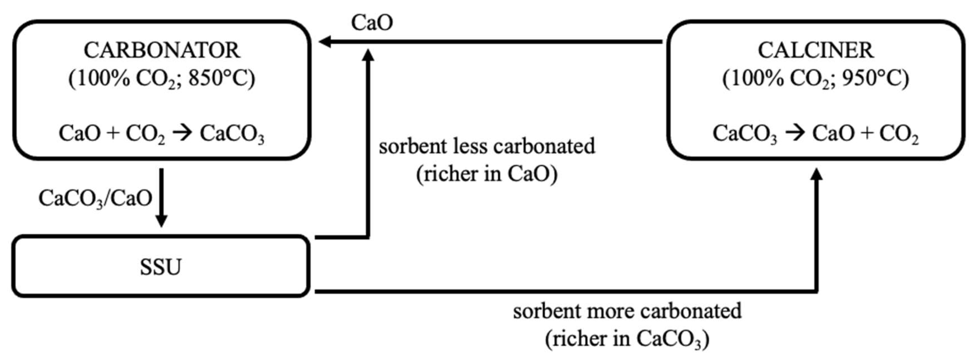
44,
45] conceptually proposed a closed-loop plant scheme with carbonation/calcination conducted at 850/950 °C under pure CO
2, inserting a Solid Separation Unit (SSU) after the carbonator to separate converted and unconverted particles, and to increase the efficiency of the process. Sarrión et al. [
46] also suggested process configurations for a closed-loop CO
2 cycle applied to TCES.
A review of the literature showed that integration between CaL and CSP is a widely investigated topic, but the effect of the FB reaction environment on the process performance still deserves investigation. When TCES conditions are used, the process is mainly studied in thermogravimetric analysers [
47,
48,
49,
50], while there are few studies in which it is assessed in fluidised bed reactors [
31,
34,
51,
52,
53]. Thus, the present study is not limited to the assessment of the deactivation of CaO in general terms, but it focuses on the specific process conditions of CaL coupled with concentrated solar radiation for energy storage. In the companion paper of this article [
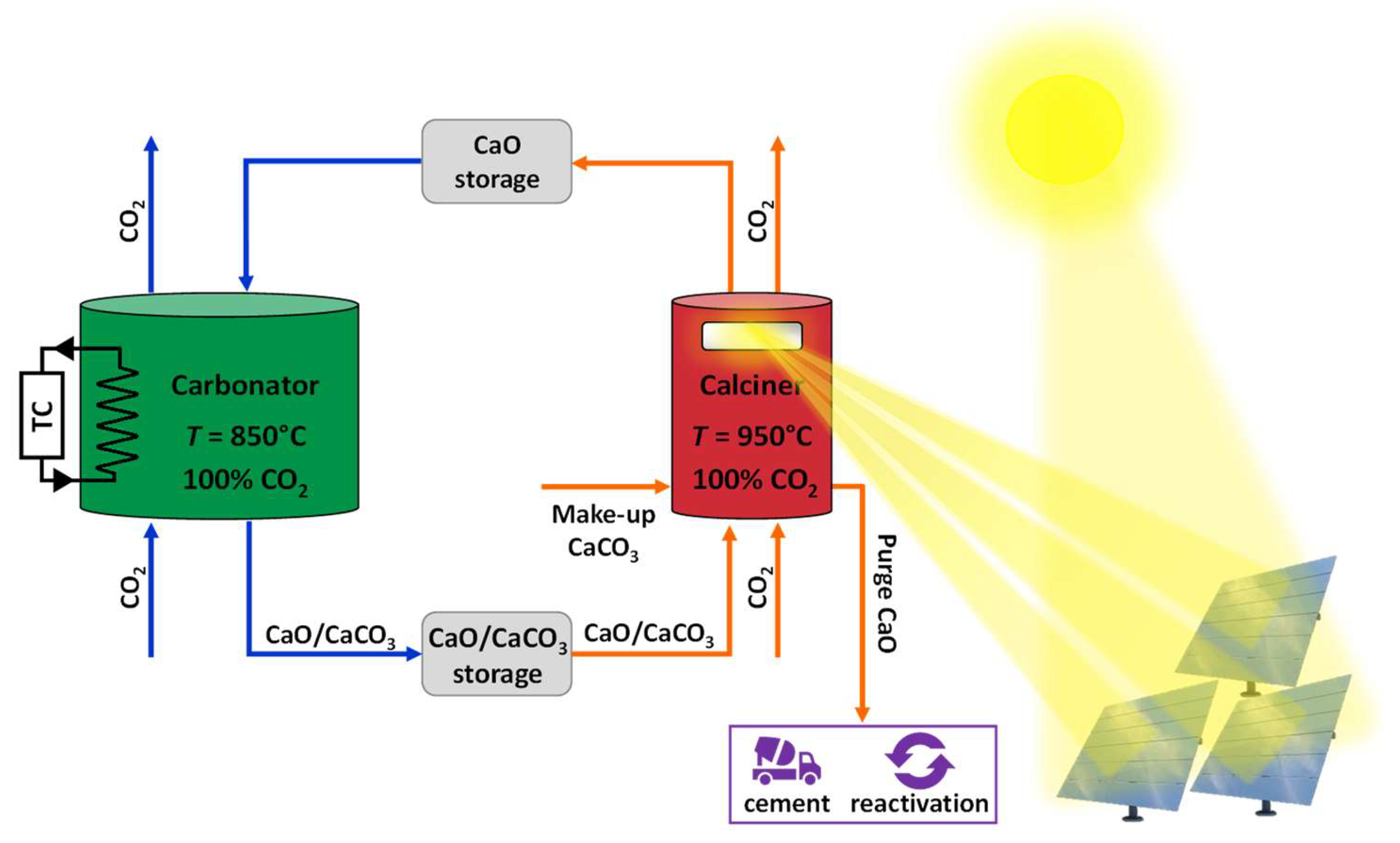
52], the study of the effect of FB fluid dynamics on the performance of an Italian limestone for TCES applications was investigated, considering carbonation/calcination at 850/950 °C under pure CO
2 (i.e., the closed-loop scheme illustrated in
Figure 1). From that work (focusing on energetic aspects as well), we have borrowed some data referring to an FB composed of limestone only (or with sand). Instead, the aim of the present manuscript is to extend the performances comparison when particles with a higher absorption coefficient in the solar spectrum (silicon carbide-based) are present in the bed. The focus was on the degree of CaO carbonation, and its effects on generation of fragments, particles bulk density and porosimetric characteristics as the bed composition changes. Furthermore, insights concerning possible interactions among sorbent, sand, and/or silicon carbide have been critically discussed. An investigation of the segregation behaviour of the bed material complements the work.
2. Materials, Methods, Equipment, and Operating Conditions
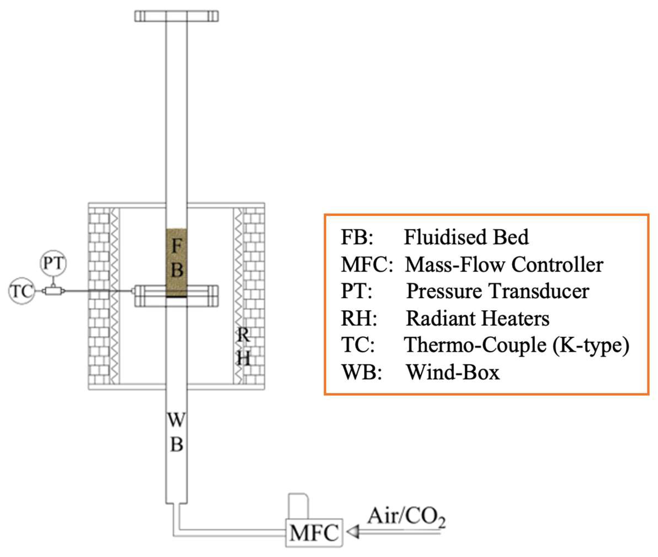
Experimental tests were carried out in semi-batch mode using a single lab-scale FB reactor, operated either as carbonator or calciner (
Figure 2). The reactor is electrically heated by semicylindrical radiant heaters (driven by a PID controller; maximum
T = 1200 °C; total power = 6.2 kW); its ID = 0.04 m and total height is 1.4 m (subdivided into windbox, bed, and freeboard). A lateral port, located few millimetres above the distribution grid, allows for temperature measurement inside the reactor, by means of a K-type thermocouple. Electronic mass flow controllers are used for gas feeding. Further details can be found in the companion paper [
52].
Three materials were adopted in the experimental process (
Table 1, where the corresponding values for the minimum fluidisation velocity (
umf) are given at the temperatures of interest):
- ○
Limestone from Sardinia (Italy)—very rich in CaCO3 (98.5%wt.), with initial particle size range between 420 and 590 μm;
- ○
Silica sand from the Ticino River (Italy), mostly silico-aluminous, initial size range 850–1000 μm;
- ○
Reagent grade silicon carbide (purity in SiC = 98.80%wt.; size range 600–850 μm). This material was chosen due to its high emissivity/absorption in the solar spectrum [
40], making it a very good candidate to improve the opto-thermal properties of the limestone bed.
Table 1.
Main properties of the materials used in the experiment.
Table 1.
Main properties of the materials used in the experiment.
| Material | Size Range [μm] | umf @ 850–950 °C [m/s] | Main Chemical Composition [%wt.] |
|---|
| Limestone (Sardinia, Italy) | 420–590 | 0.12–0.11 | 98.5% CaCO3 |
| Sand (Ticino River, Italy) | 850–1000 | 0.35–0.33 | 83.9% SiO2; 8.4% Al2O3; 2.4% K2O; 1.8% Na2O |
| Silicon carbide (r.g.) | 600–850 | 0.32–0.30 | 98.80% SiC; 0.20% C; 0.19% Fe |
CaL tests (
Table 2) were carried out at atmospheric pressure fluidising the bed under 100% CO
2 during both carbonation and calcination stages, to simulate closed-loop conditions. A test consists of a first calcination (“calcination 0”), plus
N = 20 cycles of carbonation/calcination. Each calcination or carbonation stage lasted 20 min, a time long enough to observe practical completion of the reactions. Calcination was carried out at 950 °C, while carbonation was carried out at 850 °C. As a matter of fact, looking at
Figure 3, which reports the regions of thermodynamic stability for CaCO
3 (i.e., the region where CaO carbonation is active) and CaO (i.e., the region where the reverse CaCO
3 calcination is active), under 1 atm of total pressure and 100% CO
2, carbonation can be brought up to 850 °C thanks to the high CO
2 concentration (this is positive in terms of process thermal efficiency), while one would need
T higher than 900 °C to attain calcination conditions.
Three cases were investigated (total initial bed inventory = 180 g):
- ○
A bed consisting of limestone only (under both calcination and carbonation, superficial gas velocity ug = 0.6 m/s);
- ○
A bed consisting of a 1:1 mixture of silica sand and limestone (under both calcination and carbonation, ug = 0.7 m/s);
- ○
A bed consisting of a 1:1 mixture of silicon carbide and limestone (under both calcination and carbonation, ug = 0.7 m/s).
The actual fluidisation velocities were chosen so to obtain a good compromise between acceptable fluidisation (cf.
Table 1) and limited elutriation phenomena.
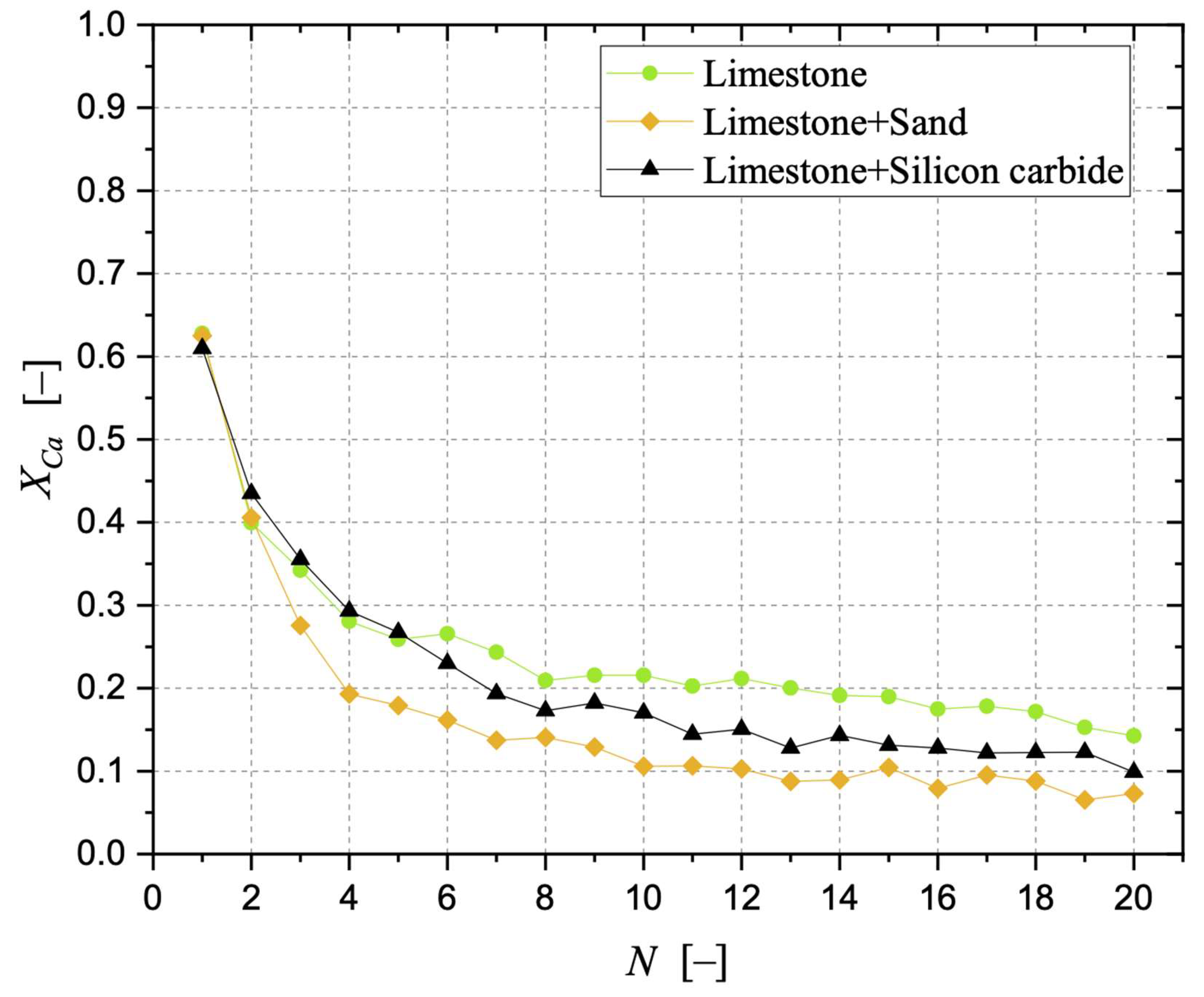
At the end of each calcination and carbonation stage, the material was retrieved from the bed. If sand or silicon carbide were present, they were separated from the sorbent via gentle sieving. The sorbent material was then weighed. The weighing procedure allowed us to calculate, for each carbonation stage, the CaO carbonation degree:
where
mcarb and
mcalc represent the overall mass of the carbonated and calcined sample, respectively,
xCaO is the mass fraction of CaO in the calcined sorbent, assuming complete calcination and the composition in
Table 1 (
xCaO = 0.973), while
MW stands for molecular weight. After weighing and before being re-fed to the FB reactor for the following stage, the sorbent material was further characterised:
- ○
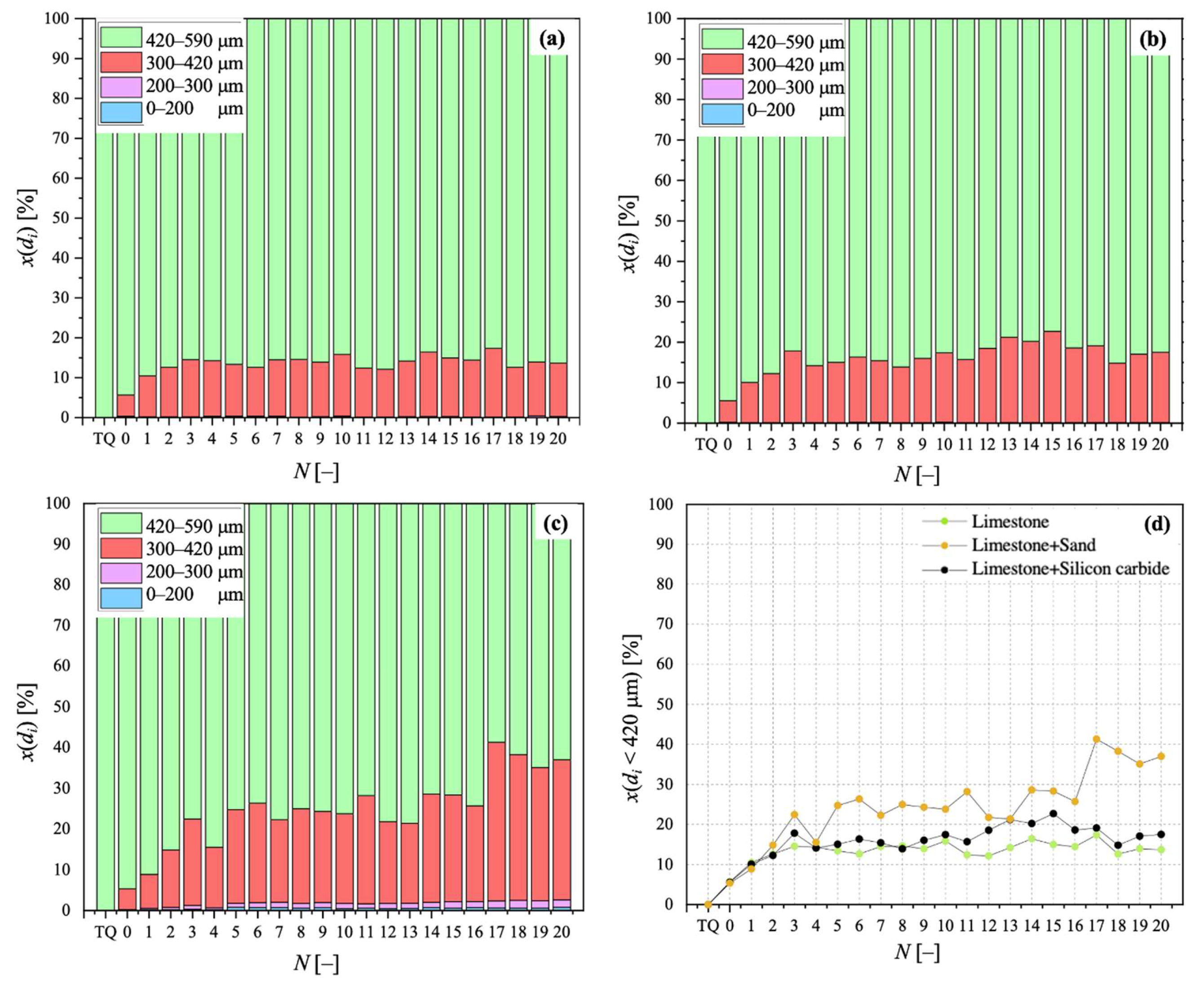
For its Particle Size Distribution (PSD), via sieving in the size ranges of 0–100, 100–200, 300–420, and 420–590 μm, so as to obtain the mass fraction for particles falling in a size bin with mean diameter di, x(di). PSD data reported in this work refer, in particular, to sorbent samples after calcination stages. PSD characterisation served as a means to analyse particle fragmentation, which is related to FB fluid dynamics;
- ○
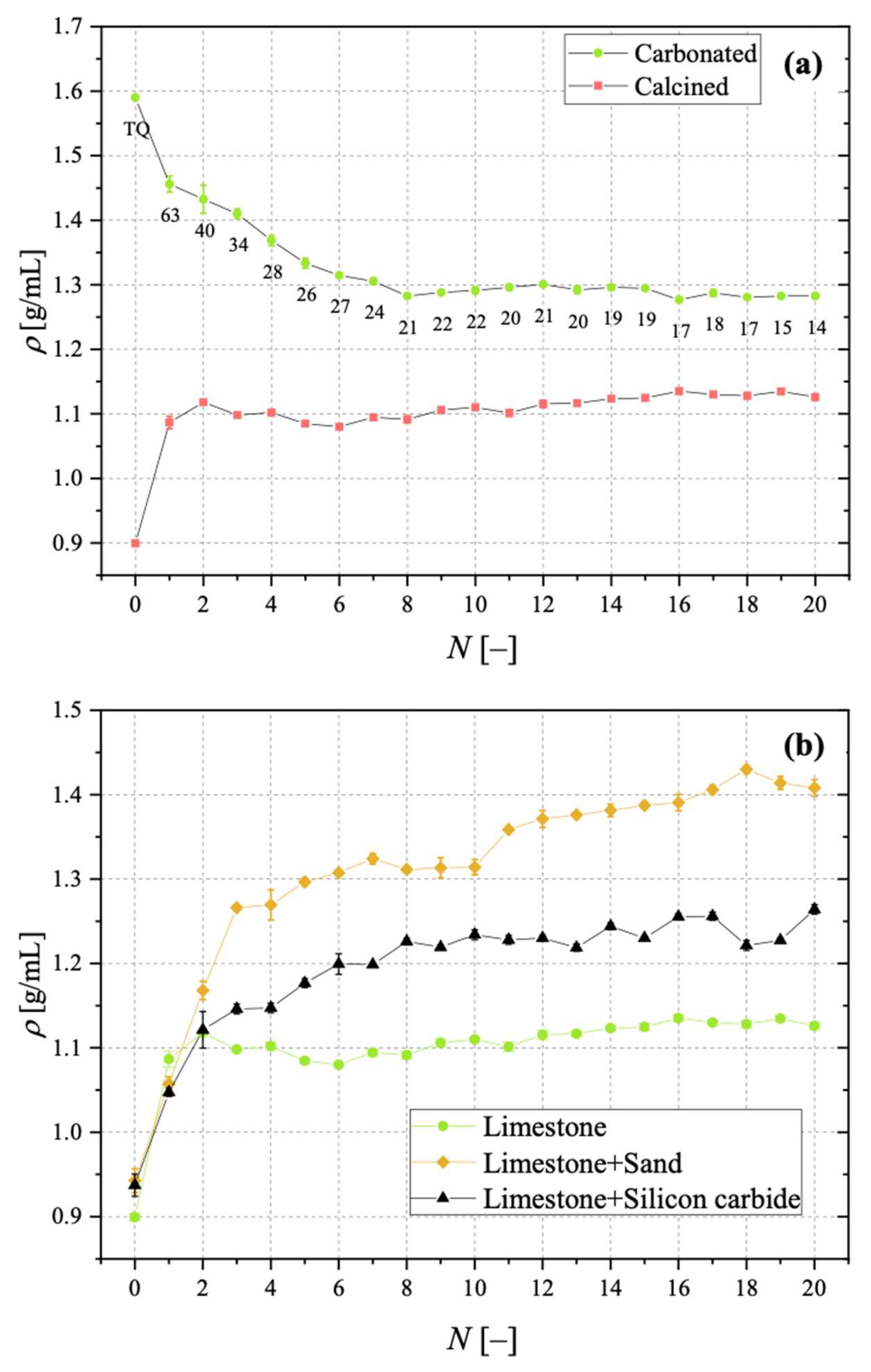
For its bulk density, ρ, by pouring the material into a 50 mL graduated cylinder and measuring the mass and the occupied volume.
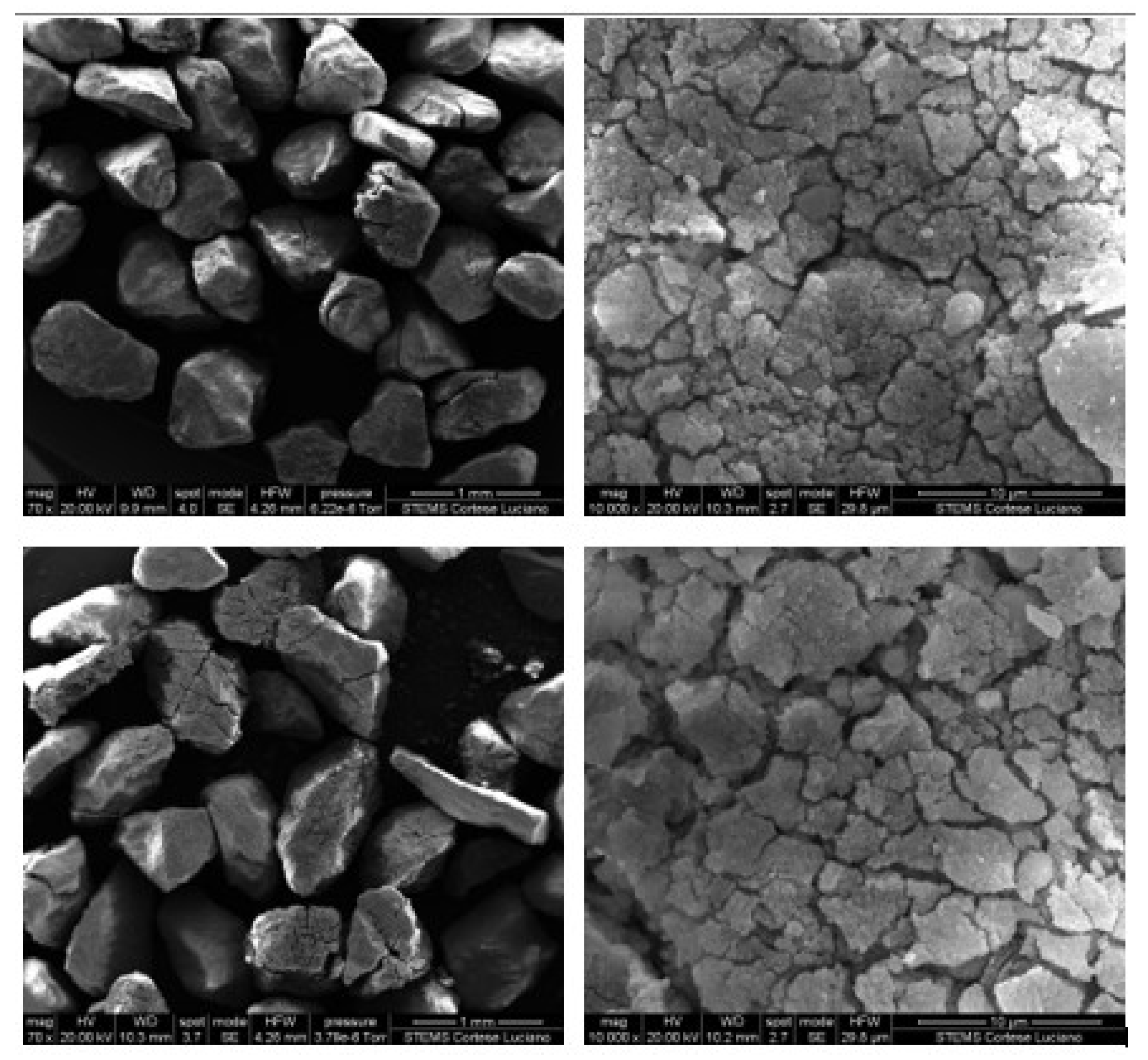
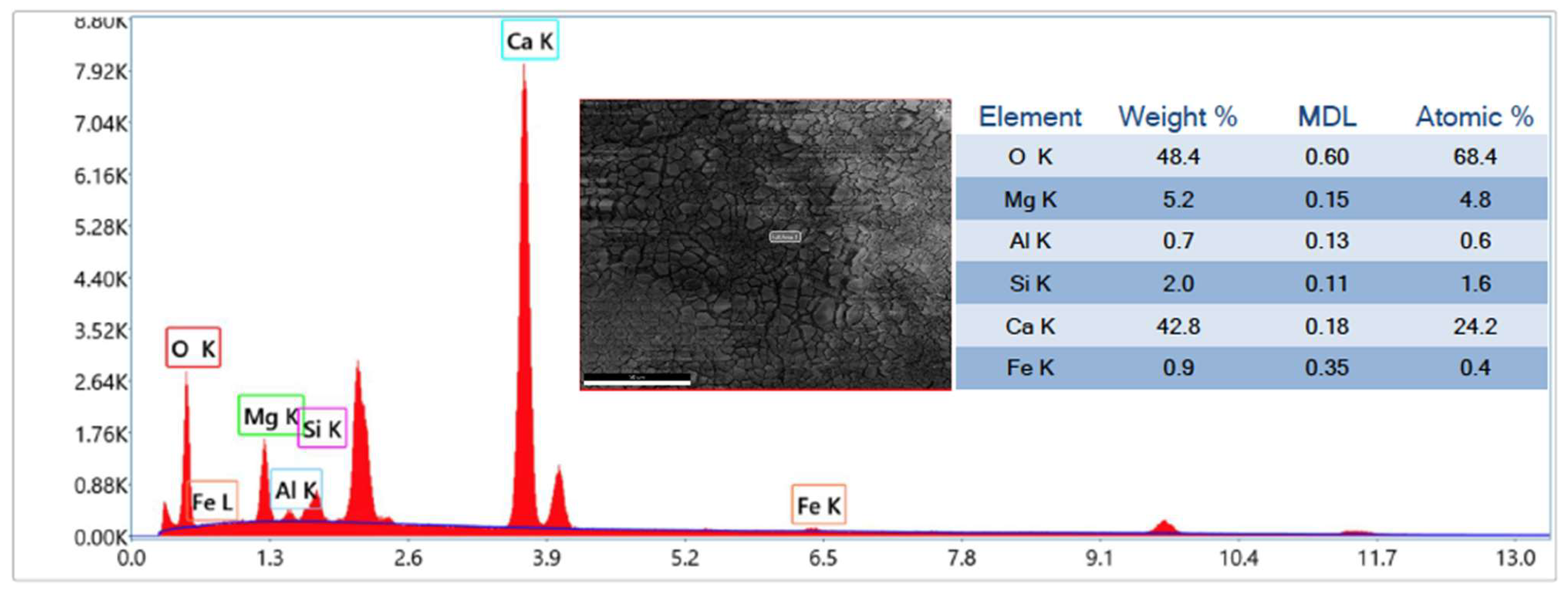
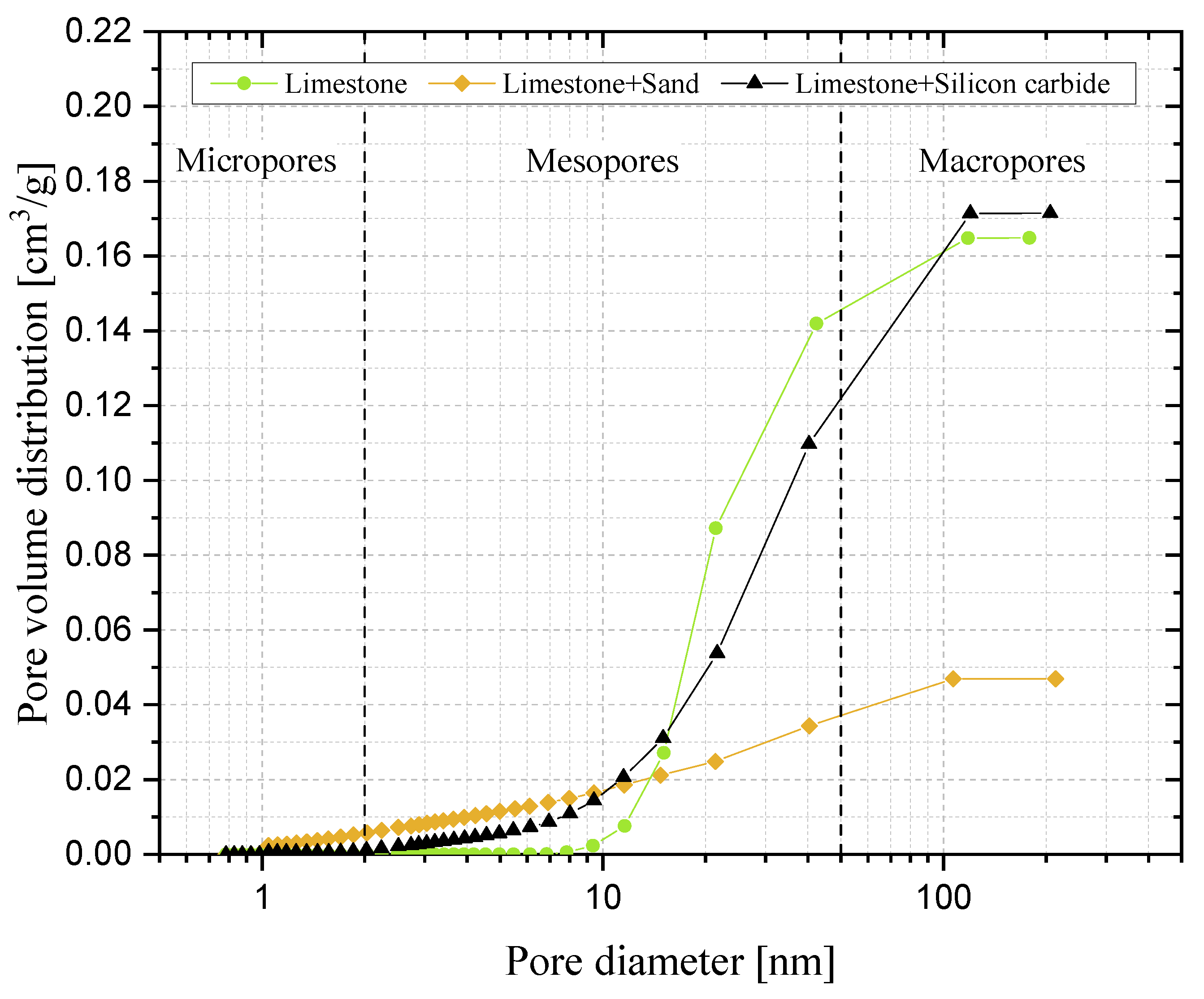
Finally, after 20 cycles of carbonation/calcination, the bed material retrieved from the reactor was scrutinised via Scanning Electron Microscopy (SEM) complemented with Energy Dispersive X-ray (EDX) analysis, at magnifications from 70× to 10,000×, and via N2-intrusion porosimetric analyses. SEM-EDX was performed using an FEI Inspect S instrument, while porosimetry was carried out through an Autosorb iQ apparatus (Quantachrome Instruments, Boynton Beach, FL, USA); desorption isotherms were post-processed with the Barrett–Joyner–Halenda (BJH) theory to deduce the pore size distribution.
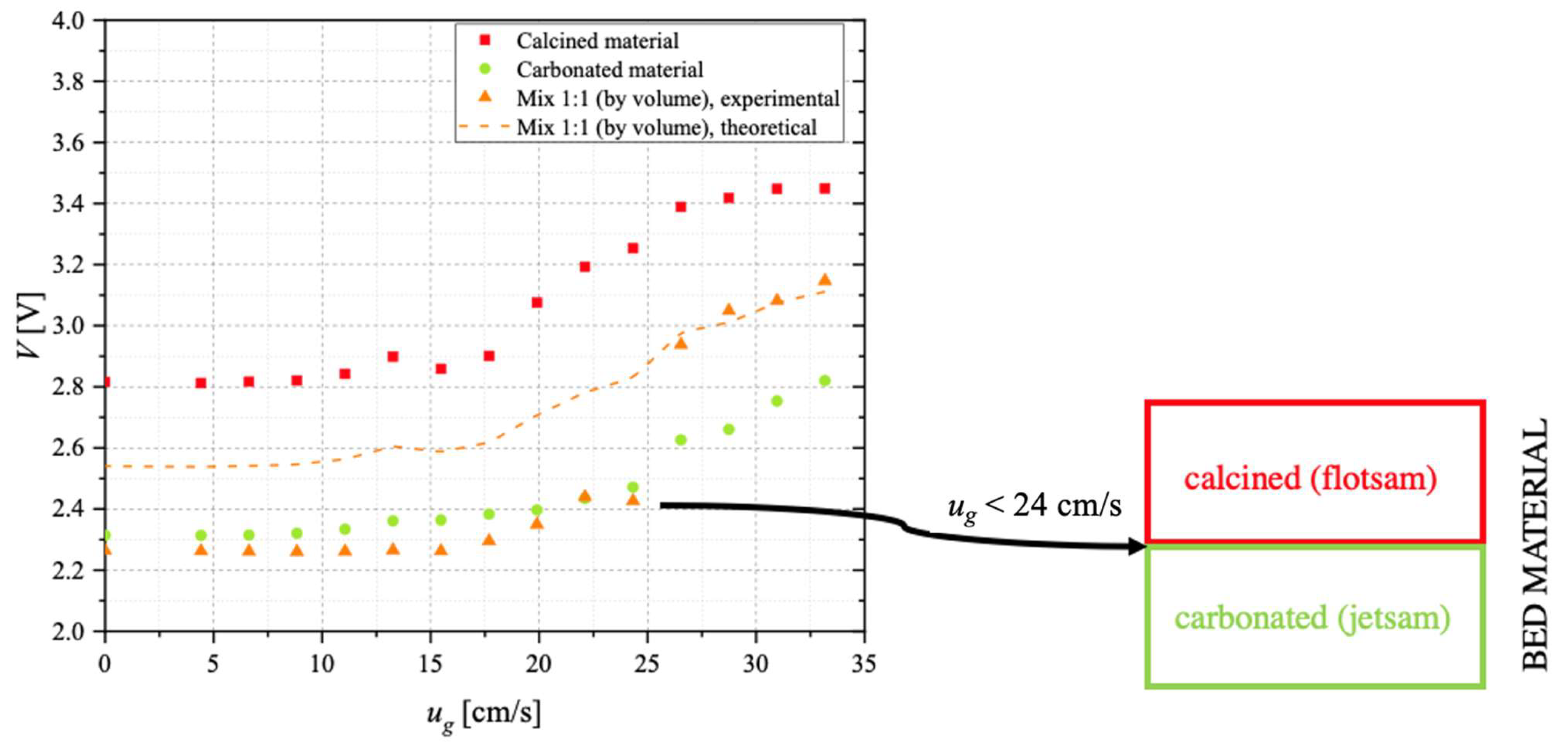
On a parallel line, the conceptual possibility of separating, in the carbonator, material with a sufficient degree of carbonation (i.e., richer in CaCO
3, to be sent to the calcination stage) from that which remains unconverted (i.e., still rich in CaO, to be recycled to the carbonator for the improvement of the process performance) has been investigated through devoted segregation tests. The underlying idea is to exploit the difference in density between more and less carbonated particles, though having similar particle size. In such cases, the material with a lower density (“flotsam”) is characterised by lower
umf and, therefore, tends to segregate in the upper part of the bed; the material with a higher density (“jetsam”) is characterised by higher
umf and tends to segregate at the bottom of the bed [
54,
55]. To this end, preliminary segregation tests have been carried out in an ID = 40 mm Plexiglas fluidisation column. The column is provided with a needle-type capacitive stainless-steel probe, immersed in the bulk of the bed. The probe central electrode has OD = 1.6 mm. This system allows the solid concentration to be indirectly determined, through the measured voltage
V: the higher
V (data acquired via a NI 9215 module through LabVIEW), the lower the solid concentration. Segregation tests have been carried out, at room temperature, with a 50 mL bed, fluidised via N
2, consisting of (i) sorbent material after the first calcination stage; (ii) sorbent material after the first carbonation stage; (iii) a mix (1:1 by vol.) of the two. This choice originates from preliminary results reported in the companion paper [
52] where, through analysis of the minimum fluidisation velocity, it can be seen that (a)
umf for the carbonated material is higher than for calcined one; (b)
umf for the carbonated material tends to decrease with
N, while
umf for the calcined material, it tends to increase with
N; (c) the maximum gap between values of
umf for calcined and carbonated material is for the sorbent after its first calcination and carbonation. In segregation tests, the N
2 flow is sent in a range of
ug = 0–0.33 m/s, large enough to sound out both fixed and fluidised bed conditions.
4. Conclusions
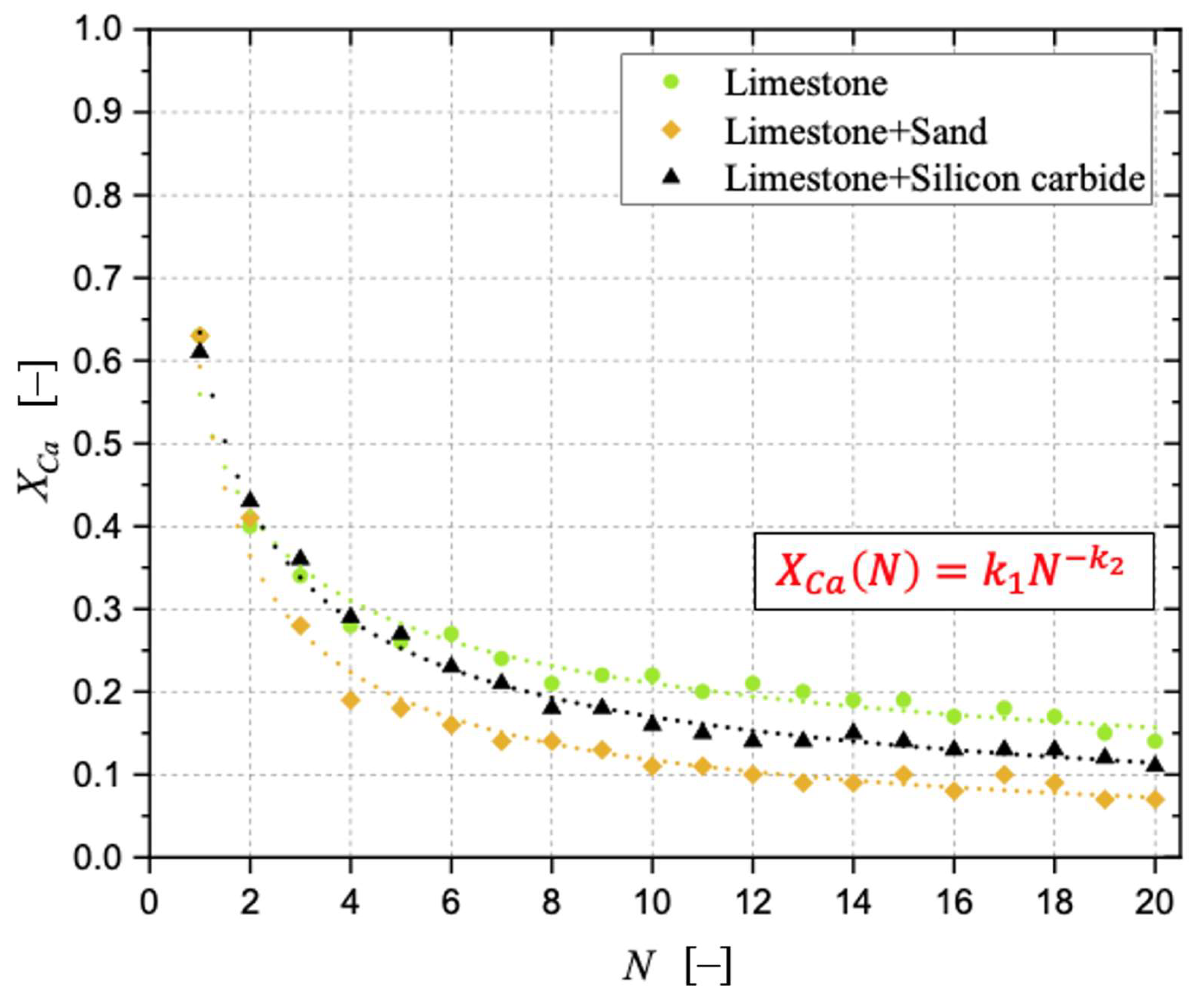
Sintering has been observed as the carbonation stages progress, negatively affecting the degree of CaO carbonation. With respect to a bed made of limestone only, the detrimental effect related to the presence of sand was more pronounced than that related to silicon carbide. The surface formation of dicalcium silicate during the calcination stage in the presence of sand cannot be neglected, as well as the possible oxidation of SiC at the expense of the sorbent when the former is present, aspects that can be responsible for the loss of “free” CaO otherwise available for CO2 capture. The application of an “initial activity & decay” equation to the conversion data confirmed the better resistance to sintering in the case of a bed of limestone only.
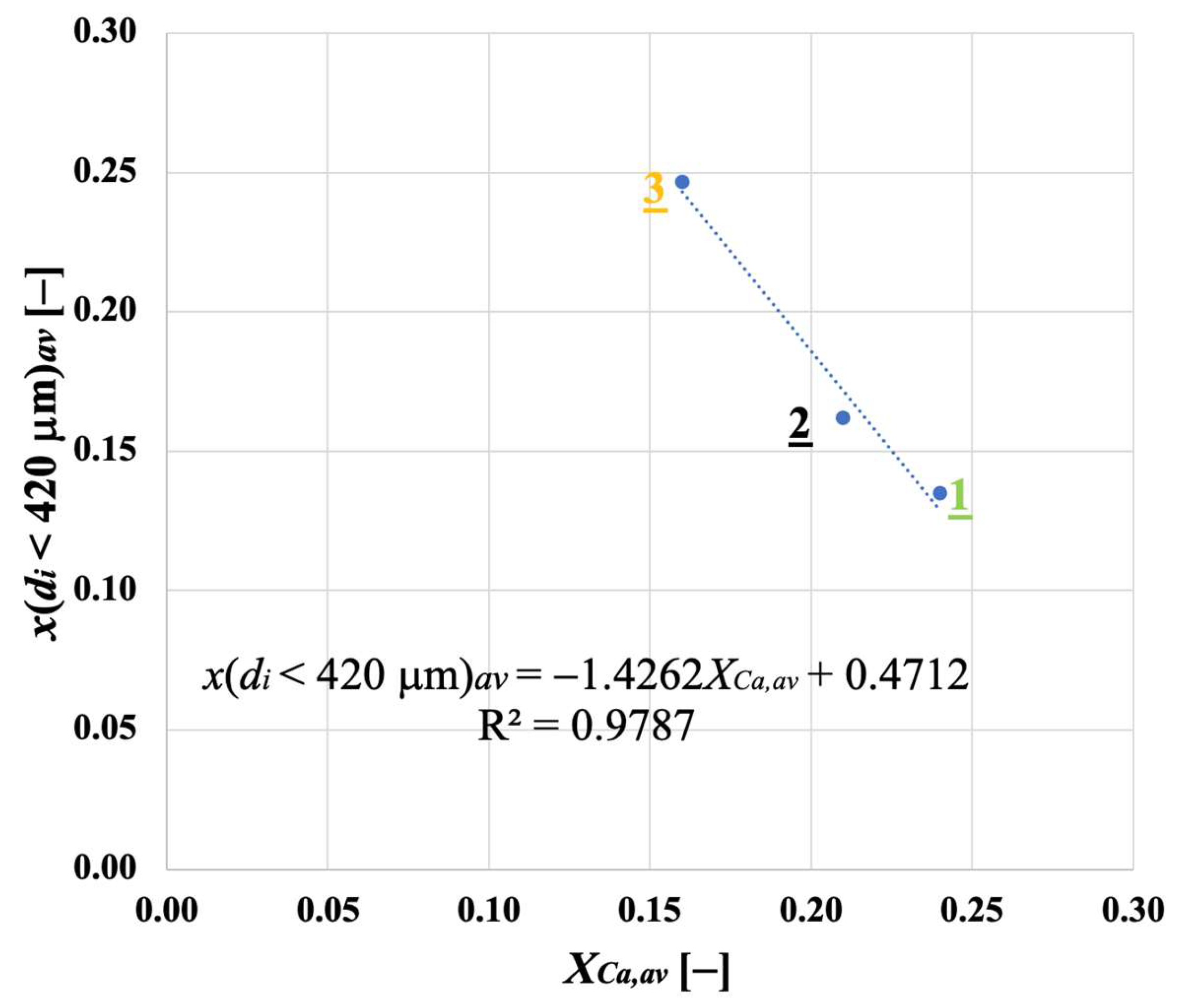
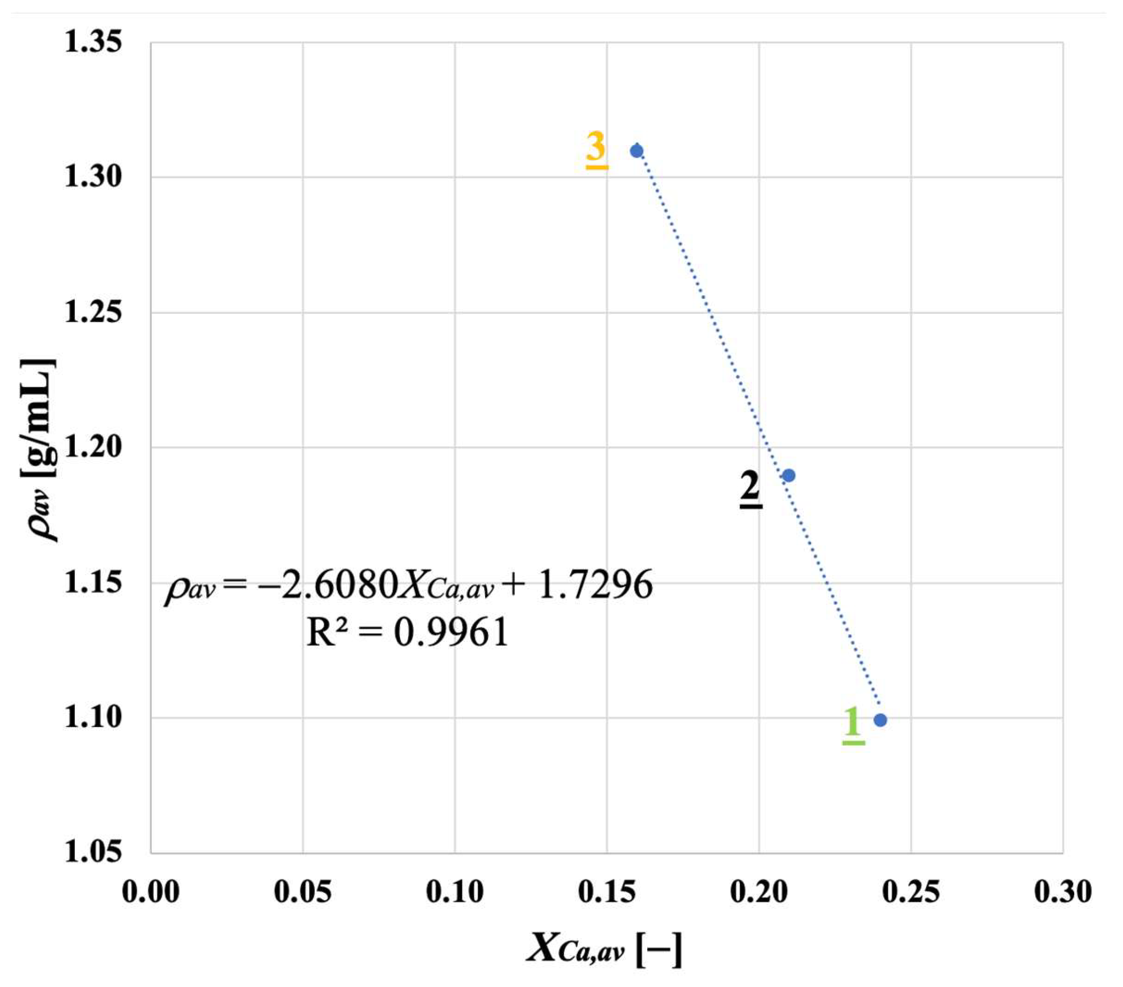
Samples showing higher values for the carbonation degree are also more resistant to fragmentation in a fluidised bed, due to the pronounced hardness of CaCO3 vs. CaO; we found a linear relationship stating that the higher the average degree of carbonation, the lower the fraction of generated fragments. We observed that the bulk density of the calcined material increases with the number of cycles (as an effect of thermal sintering). Interestingly, the higher the material reactivity (i.e., the higher the sintering resistance), the lower the density of calcined particles, and the higher the reactive porosity and the total pore volume. Again, a linear relationship between a decreasing average density of calcined particles, and an increasing average degree of CaO carbonation, has been elucidated.
Segregation tests suggested that, by choosing appropriate conditions for the superficial gas velocity, it would be possible to design a solid separation unit (downward the carbonator) able to allow the separation of the more carbonated material (to be sent to the calciner) from the material which remains unconverted (to be recycled to the carbonator), thanks to the establishment of a two-layer pattern, with carbonated material acting as jetsam and segregating at the bottom of the bed, while calcined material acts as flotsam, mostly concentrated close to the bed’s surface.

 ,
, 