Review

Design Challenges in Hydrogen-Fueled Rotary Engine—A Review

Department of Mechanical and Computer-Aided Engineering, National Formosa University, 64 Wunhua Road, Huwei, Yunlin 63201, Taiwan
*
Author to whom correspondence should be addressed.
Energies 2023, 16(2), 607; https://doi.org/10.3390/en16020607
Submission received: 24 November 2022 / Revised: 17 December 2022 / Accepted: 27 December 2022 / Published: 4 January 2023

Abstract

:
The rotary engine (RE) is a potential power plant for unmanned aerial vehicles (UAVs) and automobiles because of its structural and design merits. However, it has some serious drawbacks, such as frequent maintenance requirements and excessive fuel consumption. This review paper presents the current status of hydrogen-fueled rotary engine (HRE) technology and identifies the existing research and development gaps in combustion efficiency and performance of this engine that might benefit transportation sector. Focusing primarily on the research from past ten years, the crucial challenges encountered in hydrogen-powered rotary engines have been reviewed in terms of knock, hydrocarbon (HC) emissions, and seal leakages. The paper identifies the recent advances in design concepts and production approaches used in hydrogen-fueled rotary engines such as geometric models of trochoid profiles, port configurations, fuel utilization systems, and currently available computational fluid dynamics (CFD) tools. This review article is an attempt to collect and organize literature on existing design methods up to date and provide recommendations for further improvements in RE technology.

1. Introduction

The rotary engine (RE) has been employed as a power plant for unmanned aerial vehicles [1,2] due to its high power density, compact size, light weight, and low vibration [3]. Nevertheless, the RE still lacks rapid development and its numerous unexplored applications can be further expanded. Industry and academia have recently taken full benefit of its unique features (small engine size, lightweight, and high-power density) by using rotary engines as the power source for range extenders. A cross-sectional schematic diagram of the RE powered by hydrogen is shown in Figure 1. On the subject of RE extenders, Antonelli et al. [4] and Ribau et al. [5] conducted some useful experimental investigations. These effective uses of REs demonstrate that this engine has a wide range of potential applications in the field of extended range power production, and several automakers are actively working to further improve this technology by utilizing an RE as the power source. The REs based on conventional methods are currently facing low combustion efficiency and emission issues due to the trend of high efficiency, energy conservation, and low emissions needs of the internal combustion engine [6]. Keeping in view the market competition, the RE is in dire need of new developments in technologies suitable for upgrading RE performance. Therefore, it is crucial to develop new technologies that are appropriate for the RE in order to enhance its performance and satisfy the market demand. In this regard, several researchers have suggested new methods to enhance the RE combustion and emission features.
This article is organized into five chapters which comprehensively cover different aspects of REs. Chapter One describes the introduction to the RE, its advantages and disadvantages, and a brief history of its evolution. Chapter Two highlights the use of hydrogen as fuel and the challenges faced by the rotary engine in terms of leakages, knock, and toxic emissions when fueled by hydrogen. Chapter Three, which is the main chapter, reports the potential developments in design and various influential strategies such as fuel enrichment techniques, ignition strategies, and the exhaust gas recirculation (EGR) method considering the combustion efficiency, seal leakages, knock, and toxic emissions. Chapter Four presents the computational fluid dynamics (CFD) methods used to establish simulation models for predicting and estimating the combustion efficiency, seal leakages, and fluid flow dynamics. Chapter Five concludes the main research outcomes and addresses the research gaps and recommendations for further research and development in REs.

1.1. A Brief History of the Rotary Engine

The concept of the Wankel rotary engine, first introduced in 1951 by Felix Wankel [8], was that an orbiting rotor in the shape of a curved equilateral triangle served the purpose of traditionally moving pistons in internal combustion engines. Later, in 1961 [9], Mazda, the Japanese automaker, licensed the Wankel engine and began installing it in its vehicles. Mazda gradually upgraded the RE to improve its fuel efficiency, and by the end of that decade its sports cars had become popular in the market [10]. In the mid-1960s, the Curtiss-Wright Corporation, which controlled the North American rights to the RE, began investigating spark-assisted stratified-charge rotary engines as a method of improving power while reducing fuel consumption [11]. This exploration prompted the advancement of multi-fuel-fit rotating motors [12]. Due to uncertainties about aviation gasoline costs and availability, general aviation aircraft engines that could burn gasoline became important during the end of the 1970s and beginning of the 1980s. Because of its use in commercial aircraft at the time, the general aviation community proposed gasoline or jet fuel [13]. The National Aeronautics and Space Administration’s (NASA) preliminary engineering study identified the stratified-charge rotary engines from the Curtiss-Wright Corporation as the best design for this application above gas turbines, diesel engines, and spark-ignition reciprocating engines [14,15]. The Curtiss-Wright Corporation was granted the Rotary Engine Technology Enablement Program by NASA in 1983. The Curtiss-Wright Corporation’s rotary engine division was purchased by John Deere, Inc. in 1984 [16]. John Deere suggested the construction of multi-fuel-capable rotary engines for a variety of US Marine combat vehicles in the late 1980s [12]. John Deere and NASA tested a stratified-charge rotary engines with a brake-specific fuel consumption of 310 g/kWh (0.51 lb/hp-h) at 160 horsepower at 8000 rpm in 1986. They proposed a brake-specific fuel consumption target of 213 g/kWh (0.35 lb/hp-h) by employing super compounding, adiabatic components, a lightweight rotor, and reduced contact [15]. According to the findings of their research, a lean combination may reduce the brake-specific fuel consumption [17]. Rotary engines are also a fascination of small, miniature, and microscale powerplants. Recently, the rotating motor concept has been used for miniature electro-mechanical systems [18,19,20]. Although rotary engines are not as efficient as reciprocating engines, they can still be employed in applications where size, weight, and vibration are critical. Rotary engines can improve fuel economy by designing modified rotary engines such as the rotary Atkinson or Miller cycle engines, enhancing combustion, minimizing seal leakage, and lowering heat loss in the working chambers. Dating back to early 1990s, Mazda has been developing hydrogen-powered rotary engines [21], and then in 2003 they developed the RX8 hydrogen rotary engine which not only could use hydrogen as fuel but also gasoline as fuel. In recent years, hydrogen has gained a lot of attention for its increasing benefits [22,23,24,25,26]. The hydrogen-fueled rotary engine (HRE) can compete with the gasoline-powered reciprocating engine’s thermal efficiency and power density [27]. Moreover, the HRE produces very low HC and carbon monoxide (CO) emissions in comparison to gasoline-fueled rotary engines (GRE) [28]. HRE has a greater burst pressure and thermal efficiency than GRE [29]. Despite having low power density, the HRE is capable of producing the same power density as the GRE [30].

1.2. Goal of This Review Article

The article is aimed at highlighting the current challenges and recent advancements in hydrogen-fueled RE in the fluid power field. The challenges faced by rotary engines with regards to fuel economy, emissions, knock, and leakages due to incapable sealing—which leads to reduced combustion efficiency and unburnt carbon and nitrogen oxides (NOx) emissions—are emphasized in this article. Keeping these challenges in view, this review paper highlights the past ten years’ evolution in RE design with regards to trochoidal profiles, hydrogen usage as an alternative fuel, and the use of CFD technology. The study compiles and provides guidelines and the current focuses of industry and academia through the literature review to identify appropriate research that could be beneficial to deal with the current issues faced by the rotary engine.

2. Effects of Hydrogen Enrichment on Rotary Engine’s Performance

2.1. Hydrogen as an Alternative Fuel

At present, hydrogen is majorly fueled in automobiles either in the form of hydrogen-fueled cells (HFC) or hydrogen-fueled internal combustion engines (HICEs) [31]. Either of the two ways can attain reliable emission performance. In addition to having great emission performance, HFCs also have an efficiency of over 50%; however, due to their high cost and structural drawbacks, their design and implementation on wide scale is a great challenge [32]. HICEs, on the other hand, are currently cost-effective while being less efficient than HFCs. Additionally, a robust infrastructure can guarantee the upgradation of HICEs [33]. In the 21st century, vast contributions have been made by many countries to the progress of HICEs [34,35,36,37].
In comparison to fossil fuels, using hydrogen in internal combustion engines (ICEs) has a number of other benefits [38] including high diffusivity, high combustion efficiency, short quenching distance, high thermal efficiency, fast flame speed, and high combustion temperature [28]. However, there are three inherent drawbacks for the prevalent port injection HICE—including excessive NOx emission [39], low output power [29], and greater risk of abnormal fuel burning [40]—that hinder the commercialization of hydrogen-powered reciprocating piston engines (PEs). Specifically, backfire [41] is one the responsible factors in ICEs, which is much likely to occur during the combustion of hydrogen-powered PEs, causing a high risk of instability. Several techniques, including exhaust gas recirculation (EGR) [42], direct injection (DI) [43], lean combustion combining turbocharge [44], etc., have been implemented; however, there is a scarcity of ICE design types, which may essentially prevent the shortcomings of hydrogen as a fuel in these engines. The rotary engine [45], having high-power, low-efficiency, and poor-emissions [46], is superior in this regard from the reciprocating piston engine [47] to the extent that it is applicable in drones, sports cars and military equipment [48] due to its design merits [49]. The high-power feature enables hydrogen-fueled REs (HREs) to suffice the power requirements. Meng et al. [50] made a comparison of REs and PEs powered by gasoline and hydrogen and revealed that HREs can provide more power per displacement while maintaining a comparable degree of efficiency. In addition, they discovered that hydrogen’s physiochemical properties can considerably increase the thermal efficiency and emission of REs. It is important to note that an RE is less likely to backfire due to its unique structure [51]. HRE therefore has the potential to be a power source with zero carbon emissions because of a RE’s high tolerance for hydrogen. In fact, an HRE is inferior to a hydrogen-powered PE, which requires further analysis with regards to efficiency, durability, and fuel economy.
Despite the numerous advantages of hydrogen over traditional fuels, there are significant scientific, technical, and economic barriers that have made it challenging to switch easily from fossil-fueled to hydrogen-fueled REs. Hydrogen is more difficult to store and transport than energy produced from other fuels, such electricity or a battery, since it differs from other fuels [52]. Hydrogen needs energy to produce and is less stable than fossil fuels [53]. Specific precautions are required since hydrogen is extremely flammable and rapidly oxidizes and rusts storage containers and pipelines [54]. In order to use it as a fuel in automobiles and industrial and other energy sectors safely, its physical state requires changes [55]. Although hydrogen is often used in the chemical and refinery sectors, the costs associated with its production, storage, and transportation make it unsuitable for use in the majority of energy-related applications. At present, extensive research is being performed in expanding the scope of the energy system due to the immense advantages of hydrogen [56].

2.2. Knock Issues

Knock, which is regarded as one of the abnormal combustions in engines [57], causes significant pressure fluctuations in the combustion chamber, which adversely affects the engine’s performance and potentially causes irreparable mechanical damage [58]. According to research and the Motored Octane Number, hydrogen can be regarded as a superior anti-knock fuel; yet, under identical operating conditions, HICEs often exhibit greater knock than ICEs powered by gasoline [33]. According to Dhyani et al. [59], knock in HREs raise engine component temperatures, which might result in hot spots and severe backfire in succeeding cycles and is undesirable to the engine’s stability. Figure 2 shows the correlation between backfire and knocking. The combustion analysis was carried out by the authors on a cyclic basis in order to investigate backfire at various equivalency ratios. The combustion conditions were examined using the recorded in-cylinder pressure-crank angle data from each cycle as input. The cycle-based analysis was performed at an equivalent ratio of 0.82 to determine the backfire occurrence. A rapid fluctuation in pressure at the end of the compression stroke in the 444th cycle indicates a high-intensity knock. Backfire was observed during the suction stroke in the 445th cycle, causing the peak pressure to drop to 25 bar. The 446th cycle had knocking without a backfire. As additional cycles passed, the knock level steadily rose until the engine stopped on the 490th cycle.
Based on the research of Szwaja [60], unlike gasoline-fueled REs, which often experience knock at the end of combustion, HREs experience knock immediately after ignition and during the entire combustion process. In a further study [61], Szwaja and Naber investigated that the fast and unstable burning of hydrogen in HICEs generates weak knock. The light knock occurs during the combustion at CR = 11. As shown in Figure 3a, the pressure pulsations start at 0°. Even the highest pressure pulsation does not exceed 0.1 MPa and no irregular pressure peaks are observed. This depicts, the combustion of hydrogen does not cause auto-ignition. On the contrary, spontaneous burning of the end gas generates strong knock. Figure 3b indicates pressure pulsation condition during combustion at CR = 12. It can be seen the pressure pulsation peak drastically rises up to 0.32 MPa. The abrupt rise in pressure pulsation occurs due to auto ignition which results in severe knocking.
In contrast to conventional fuel, the knock of a hydrogen engine is caused by the mutual development of flame and pressure wave rather than the end mixture spontaneously igniting [62]. Salvi et al. [63] reported that as the equivalence ratio increases, an HRE is more prone to knock. Szwaja [60] found that knock level has a direct relation with the combustion rate in HICEs. The knock intensity for the ninety-fifth percentile of peak pressure vs. the maximum rate of mass fraction burnt at three different compression ratios is shown in Figure 4. At a compression ratio of six, the knock is minor. When the compression ratio reaches eight, the knock is significant, but it does not intensify and affect the engine as the spark timing advances. A considerably high knock of approximately 100 kPa occurred at a compression ratio of 10. The knock increases rapidly as the 50% mass fraction burnt approaches the top dead center (TDC), which corresponds to advancing spark timing.
Scholars have shown that lubricating oil has a significant effect on knock in HICE [64], while the spark plug configuration also plays a key role in knock [57].

2.3. Leakage Issues

Although the RE has certain benefits over reciprocating engines, lower combustion efficiency [65] and high HC and CO emissions [66] are the major shortcomings because of the significant gas leakage issues [49]. The leakage is one of the main drawbacks of the RE. The small molecular weight and fast flame speed of hydrogen leads to greater risk of leakages in HREs in comparison to GREs [67]. The flame propagation speed at various hydrogen mass fractions and equivalence ratios is shown in Figure 5. The solid curved line in the figure represents the normalized laminar speed (indicated by the arrow to the left y-axis) as a function of hydrogen mass fraction in total mixture. The doted curved line represents the hydrogen mole fraction in total fuels (indicated by the arrow to the right y-axis) as a function of hydrogen mass fraction in total mixture. The normalized laminar flame speed is the ratio between SL (laminar flame speed of gasoline–air mixtures at an equivalence ratio Φ of 0.75) and SL0 (laminar flame speed of hydrogen–gasoline–air mixtures under different hydrogen mass fractions βH2 at an equivalence ratio Φ of 0.8). The highest ratio is approximately 1.4 when the hydrogen mass fraction is between 1.5% and 2.0%, and the highest flame speed is thrice that of SL0. As a result, the optimal hydrogen mass fraction and distributions efficiently increase the flame speed.
In addition, the inherently longer sealing line makes sealing a challenging task, because the geometry of an RE’s sealing system is much more complicated than that of a PE, comprising the apex seals, corner seals, side seals, and the seal springs that activate the sealing. The primary leakage in an RE gas sealing system is the apex seal leakage, especially for an HRE [68], and the apex seal leakage ranges in 65–75% of the total leakage. Several factors play their role in the apex seal leakage. Depending on the location and mechanism, the apex seal leakage consists of the spark plug cavity, the side piece, the corner seal (refer to Figure 6), the groove flanks, and the running face [69].
The major leakages among all these types are the leakages at the spark plug cavity and the corner seal gap. In his research, Picard reported that the leakages at the spark plug cavities and the corner seal are nearly 29% and 28% (refer to Figure 7) of the total leakage [70].
The fuel injection method of a peripheral-ported natural gas blended with hydrogen in an RE under the action of apex seal leakage was investigated by Fan [71]. Fluid flow and flame propagation in an RE can be significantly altered by the apex seal leakage [72]. Additionally, the apex seal leakage to a greater extent affects the motion of the air fuel mixture and the burning process in REs [73]. The high temperature and high pressure fluid in the combustion chamber leaks through the clearances into the adjacent chambers (as shown in Figure 8), directing the flame movement towards the compression chamber [74].
In a one-dimensional simulation analysis, the volumetric efficiency and peak pressure of REs are drastically reduced due to the apex seal leakage [75]. Additionally, the greater the apex seal leakage, the shorter the time span of the choked flow [76]. The leakage comparison between hydrogen and air by Hsieh [77] shows that a greater vortex number of hydrogen than that of air results in a greater risk of leakage by using hydrogen as fuel as compared to air. According to research on the impact of apex seal leakage on NOx emissions, final NOx concentrations significantly decrease as apex seal leakage area increases. In addition, the rise in HC content at low engine rpm is mostly caused by apex seal leakage [69]. Zhang et al. [78] investigated the variation in oil film thickness between the apex seal and the epitrochoidal housing of a rotary engine at various operating speeds (7000, 9000, 11,000, 13,000, 15,000, and 17,000 rpm). The apex seal leakage considerably alters gas pressure, further affecting the oil film thickness. Figure 9 depicts the pressure distribution of oil films. The leading arc has a relatively higher oil film pressure than the trailing arc. The maximum pressure value increases significantly as the crank angle turns. Because of the periodic change in gas pressure in the leading and trailing chambers, the apex seal moves laterally. As a result, the gas pressure varies drastically with lateral movement, and the abrupt change of gas pressure affects the pressure distribution.
Currently there is a lack of research on the mechanism of spark plug cavity leakage, with the majority of studies concentrating on the ignition performance of spark plugs. Harikrishnan also reached the conclusion that the combustion rate and fuel conversion efficiency depend on the spark plug location relative to the chamber walls [79], and Hwang found that combustion efficiency can be improved by an earlier leading spark plug ignition for REs [80], while the combustion efficiency can be enhanced by reducing the distance between the leading spark plug and the top dead center line. Figure 10 shows temperature distribution at various spark plug positions.

3. Research Methods

Apex seals are located at the apexes of the rotor, and the configuration is such that the seals engage with the inner wall of the epitrochoidal bore. As the rotor rotates, the apex seals are displaced relative to the inner walls of the epitrochoidal bore but remain in sealing engagement throughout the rotor operation. The apex seals have always been one of the most critical parts in rotary engines [81]. It is not surprising that development of apex seals is one of the subjects that has received the most attention by engineers working on rotary engines. The poor sealing of the engine chambers at the rotor apexes leads to lower fuel efficiency and high hydrocarbon emissions.
Sealing performance has been improved over the years, but the rotary engine is still in dire need of improvement in terms of the fuel leakage, wear, friction, fuel consumption, and emissions. Targeting these challenges, the critical factor determining improvement in performance is the rotary engine design. Various methods used in recent years to design REs, following the apex seal profiles for a wider range of RE rotor profile varieties, conforming housing profiles, and different apex seal configurations for a wider variety of optimal sealing possibilities have been reviewed in this article.

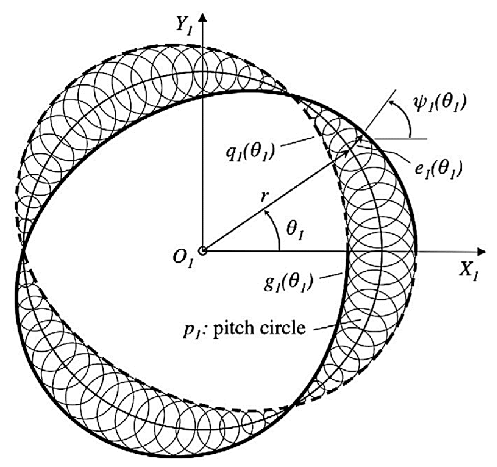
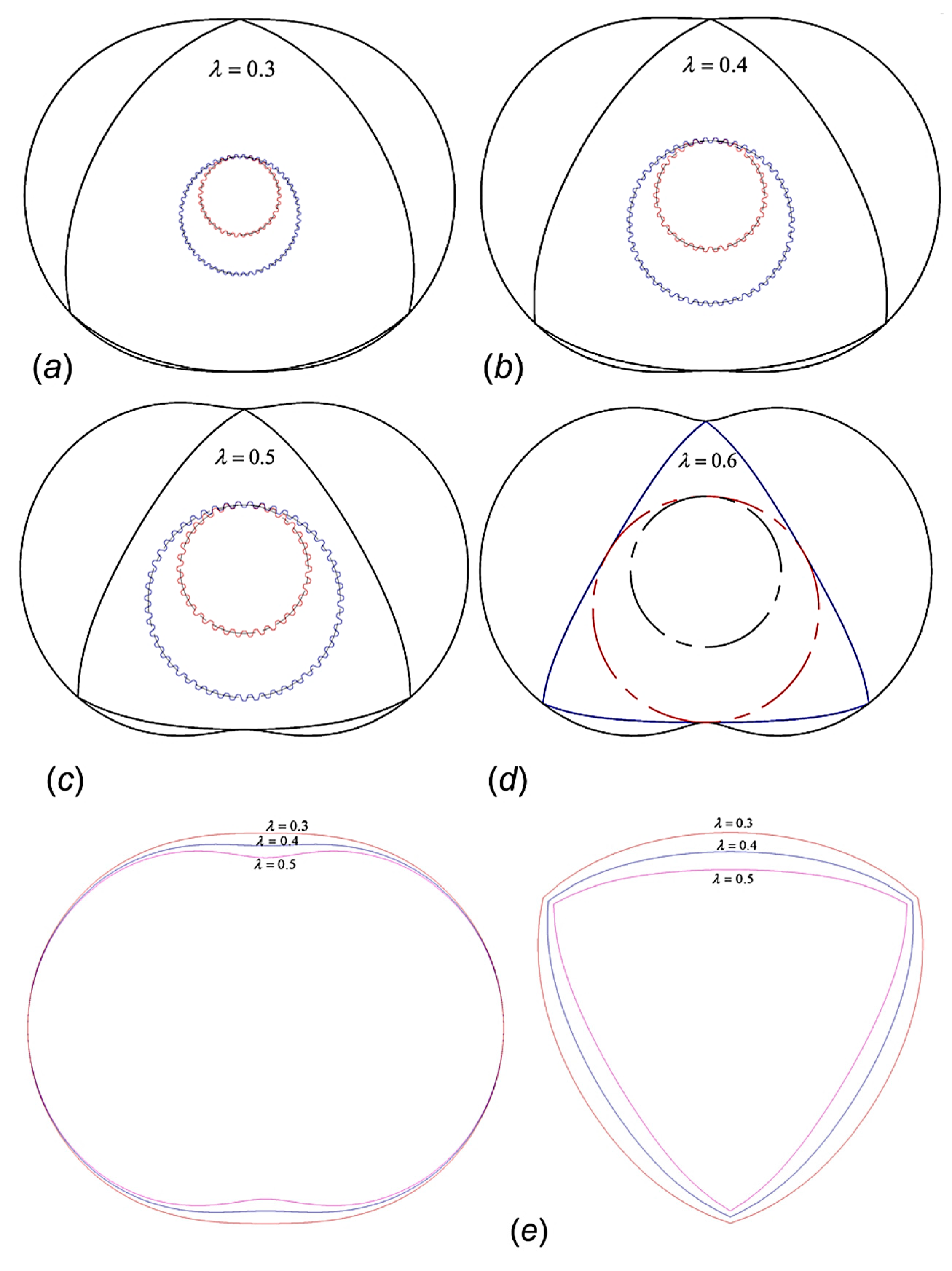
3.1. Trochoidal Profile Methods

Until 2013, rotary engines were designed using trochoidal type housing profile, while spring loaded apex seals were employed to seal the chambers at the rotor apexes. Rose and Yang for the first time developed the design of rotary engines based on the apex seal profile deviation function (DF) approach of conjugate pair design. Using this method, the engine housing is constructed conjugate to the apex seal while the conformity between housing and the seal improves the sealing ability and efficiency, thus improving the engine efficiency. In addition, the load at the apex seals can be minimized, thus improving the friction losses on the rotor apex. Moreover, the authors designed the housing for a broader apex seal, consisting of several seals employed at each rotor apex. When each of the apex seals are in direct contact with the housing, various constraints are constructed to prevent gas leakage. Due to interference between the seals and the bore, the feasibility of wider apex seals has not been proven for conventional engines. In a subsequent study, the DF approach for engine design by apex seal profile shows best sealing between the seal and bore. They reported that the DF method allows the selection from a range of apex seal profiles and geometries, and wider apex seals have a greater sealing index [82,83,84]. Figure 11 represents the deviation function method for drawing the envelopes of the deviation circles.
Hsieh and Cheng used CFD methods to analyze the effect of variations in the geometric design curve (K factor) on the flow characteristics of rotary engines. They found that a lower K factor produces more leakage, high internal pressure variations, and unstable inlet pressure. In contrast, a high K factor reduces the leakage followed by lower internal pressure variation, and stable inlet pressure [85]. Figure 12 shows the design for various K factors of REs. In Figure 12a–c, the sun gear constructed from the theoretical rolling circle is shown in blue and the fixed circle is shown in red. Based on the movement trajectory principle of points the housing curve constructed should confirm with the rotor profile such that the fixed circle rotates along rolling circle. Figure 12d presents design results of three different K factors analyzed. The small K factor (K = 6) is shown in pink color, the medium K factor (K = 7.5) is shown in blue color and the large K factor (K = 10) is shown in red color.
Bhoir and Tambuskar, using CFD methods, revealed that the deviation function approach for epitrochoidal engine design is instrumental to generate several profiles from noncircular pitch curves without using higher order nonlinear equations. Noncircular pitch designs can improve the chamber shape, the apex sealing, or the thermodynamic phase timing at varying speed ratios. By adjusting the pitch curves, varying the speed ratios between the rotor and main shaft can change the velocities of the apex seals. Thus the DF-designed profiles allow more design flexibility and enable variable speed ratios [86].
Hsieh, in a recent study, has proposed chamber profiles and triangular rotor profiles in an RE. Using the epitrochoid and envelope concepts for the dynamic analysis of the kinematics and stresses at the apex seals, it was found that a higher trochoid ratio decreases system stability and raises vibrations, stress variations, and stress intensity. When taking into account combustion chamber displacement, compression ratio, operation stability, and parts load capacity, the trochoid ratio of 0.4 is recommended [87]. The theoretical profile design results for various trochoid ratios are presented in Figure 13. Figure 13a–c shows the sun gear constructed from the theoretical rolling circle shown in blue and the fixed circle shown in red for trochoid ratio λ = 0.3, 0.4 and 0.5 respectively. Figure 13d shows the sun gear constructed from the theoretical profile for trochoid ratio λ = 0.6, which means the internal gears are not feasible and thus for production the trochoid ratio is proposed to be less than 0.6. Figure 13e presents design of housing and rotor profile for three different trochoid ratios. The large, medium and small trochoid ratios (λ = 0.5, 0.4, and 0.3) are shown in pink, blue and red color respectively.

3.2. Fuel Utilization Methods

Despite its benefits, REs confront several technical hurdles, including flame propagation issues [88,89] due to the its inherent structure and large surface area, which results in high fuel consumption and hydrocarbon emissions [90].
Enhancing combustion efficiency is the most effective way to address the existing challenges of REs [91]. Numerous innovative techniques have been suggested to increase the combustion efficiency of REs. Amrouche et al. [92] used hydrogen in an RE and improved the combustion and heat efficiency, reduced hydrocarbon emissions, enhanced engine stability and engine life. Fan et al. [93], studied the influence of injection angle and injection timing on hydrogen distribution in an RE. For improving the combustion efficiency, their findings suggest the hydrogen injection angle of +45° and hydrogen injection timing of 155°CA as the optimal hydrogen injection strategy. This strategy yields a higher concentration of hydrogen near the spark plug and lowers the leakages; however, this approach increased NOx emissions. Yang et al. [67] revealed that by combining both side port system and a peripheral port intake system increases the peak cylinder pressure and thermal efficiency by 4.5% and 3.9%, respectively, reduces the formation time of the main flow field in the cylinder, increases the average in-cylinder flow velocity, and accelerates the flame propagation velocity in the same direction as the main flow field. According to Pan et al. [94], as the intake port timing was advanced, the engine power initially increased and subsequently declined. Additionally, they noticed that if the inlet or outlet port opening duration or outlet port timing were prolonged, the engine power enhanced.
Despite the fact that all of these techniques can increase rotary engine efficiency, flame propagation remains a challenging problem in rotary engines due to the difficulty of the flame dispersion in the direction opposite to the rotor movement. This problem is a built-in feature of RE combustion. It causes substantial unburned hydrocarbon (HC) emissions and incomplete combustion. In order to solve this issue, the cylinder must have sufficient fuel distribution, which entails distributing as much gasoline as feasible to the combustion chamber’s front side while using an effective injection technique [95]. By adjusting the fuel injection time, injection direction, injection pressure, and other variables, a direct injection technology may effectively regulate the fuel distribution in the cylinder [96]. Direct injection is the most effective method to counter incomplete combustion of the RE [97]. Peter et al. [98] observed that the fuel distributes irregularly when the fuel injection timing was delayed. Meanwhile, for advance fuel injection timing, both the in-cylinder pressure and the gas temperature reduced. Chen et al. [99] investigated the effect of fuel injection time on the air-fuel mixing and combustion processes of a dual-fuel natural gas diesel rotary engine. Their findings revealed that by delaying the fuel injection timing, the mixture became more concentrated due to a shorter mixing period. Delaying the injection time raised the cylinder pressure and combustion speed. However, because of the high fuel concentration, soot and CO emissions drastically increased. Sergey et al. [100] discovered that various injection approaches resulted in diverse fuel distributions, and that several injections may tolerate a larger equivalency ratio in order to attain a better power density. Ji et al. [101] demonstrated that when the injection time was near the top dead center (TDC) and the fuel spray angle was greater, the fuel enrichment region shifted forward from the rear to the front side of the combustion chamber. These results demonstrate that an adequate fuel injection method may increase RE performance. The combined effects of oxygen intake, as well as intake pressure and temperature at various elevations on early flame development, combustion dynamics, and exhaust emissions of small-scaled REs were computationally explored by Zou et al. [102]. Their findings revealed that intake oxygen enrichment enhances the generation of hydroxyl (OH), O, and H radicals, which resulted in considerable improvements in early flame development, particularly near the leading spark plug. Ji et al. [101] investigated the influence of injection height and injection angle on mixture formation and combustion in a direct injection GRE. The injection angles were 0°, 25°, and 50° for the three injection positions, respectively. Their findings demonstrated that the upper injection position serves to concentrate fuel distribution towards the spark plug, whereas the lower injection position would direct fuel to the rear of the combustion chamber. Chang et al. [103] investigated the impact of combining port injection with direct injection in a GRE. The injection point is located along the longitudinal axis, and the injection direction is downward. Their findings revealed that direct injection produces a greater mean in-cylinder pressure than port injection. Earlier studies [104] indicate that deviating the intake tube angle to the left can cause a significant tumble movement in the cylinder. Since tumbling flow has high kinetic energy than swirling flow, it is capable of accelerating the mixing of fuel and air. Tumbling flow is a key source of turbulence, which can enhance combustion. Shi et al. [46] examined the effects of an RE with a new turbulence-induced blade arrangement. Their findings demonstrate that turbulence can increase the combustion and thermal efficiency of the rotor chambers.
Research conducted by Wang et al. on the enrichment of hydrogen by direct injection in an RE with various gas injection shapes (trapezoidal, wedge, slope, triangular, and rectangular) revealed that the rectangular shape produces a faster flame speed, a higher peak pressure in the cylinder, and a larger knock index (KI) [105], as shown in Figure 14.

3.3. Ignition Methods

Scholars have examined the in-cylinder combustion process and ignition mode in order to solve the combustion issues induced by the intrinsic structure and operating mechanism of REs. With regards to ignition mode, Jiao et al. [106] developed an in-cylinder spark ignition (ICSI) system to increase the RE’s ignition performance. The electric spark produced by this ICSI mode is positioned inside the cylinder, allowing for direct ignition of the mixture. Zambalov et al. [107] used the laser ignition method to enhance the ignition stability of an RE. The results demonstrated that laser ignition can achieve high-energy ignition of the mixture in the cylinder, considerably increasing the combustion rate. Furthermore, the turbulent jet ignition method has been applied in reciprocating engines, bringing attention to the advancement of RE ignition methods. Currently, only Taskiran et al. [108] have performed early computational modeling investigations on REs by utilizing the turbulent jet ignition method. The findings show that turbulent jet ignition may achieve multi-point ignition, which is a viable ignition mode for rotary engines. Nevertheless, it is evident that research on the jet ignition mechanism in REs is severely lacking.

3.4. Exhaust Gas Recirculation (EGR)

Focusing on emissions, output power, and backfire concerns, HREs could be utilized as great replacements to reciprocating gasoline engines, which is still challenging for hydrogen-enriched reciprocating piston engines. However, the NOX emissions and the strong knock [51] are generated by the HRE’s irregular thermal load and expanded combustion chamber [50], which perplexes hydrogen-powered reciprocating engines as well [109]. Therefore, a solution to these problems must be explored to address the disadvantages of HREs.
Exhaust gas recirculation (EGR) is one of the effective approaches to enhance ICE combustion [110]. EGR was originally developed for compression ignition internal combustion engines, and it also performs well in spark ignition internal combustion engines (SI) [111]. In addition, EGR is also an effective method to significantly reduce NOx emissions [112] and knock [113] in ICEs, particularly for HICEs prone to high NOx emissions [39]. Verhelst et al. [114] found that EGR is a significant means of increasing power output and thermal efficiency while reducing NOx emissions. EGR’s thermal and dilution effects reduce cylinder temperature, thereby decreasing NOx production. EGR’s knock suppression allows the ICE to provide a greater maximum power output during high load conditions, where thermal efficiency is often compromised to minimize knocking [115]. EGR is often classified into two types: hot EGR and cold EGR. In the former, the exhaust gas is mixed directly with the fresh charge, while in the latter, the cold exhaust gas is mixed with the fresh charge. The primary constituents of the exhaust gas in HICEs are nitrogen (N2) and vapor, with the former having a lesser specific heat capacity than the latter, resulting in a better thermal effect of the hot EGR versus the cold EGR. The high temperature of the hot EGR, on the other hand, results in a lesser charge in the cylinder. Chaichan [116] analyzed hot and cold EGR in an HICE and determined that cold EGR enables greater volumetric efficiency, lower exhaust temperatures, and fewer NOx emissions than hot EGR. Safari et al. [117] studied the use of EGR in HICEs and concluded that cold EGR is superior than hot EGR in terms of reported thermal efficiency and performance.

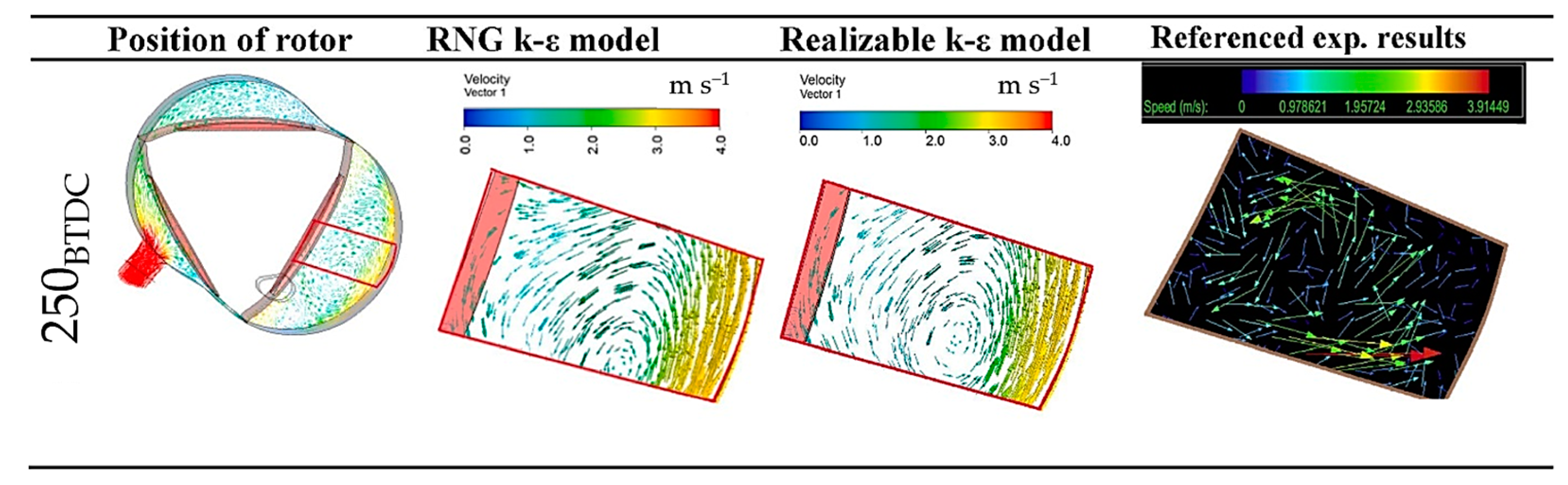
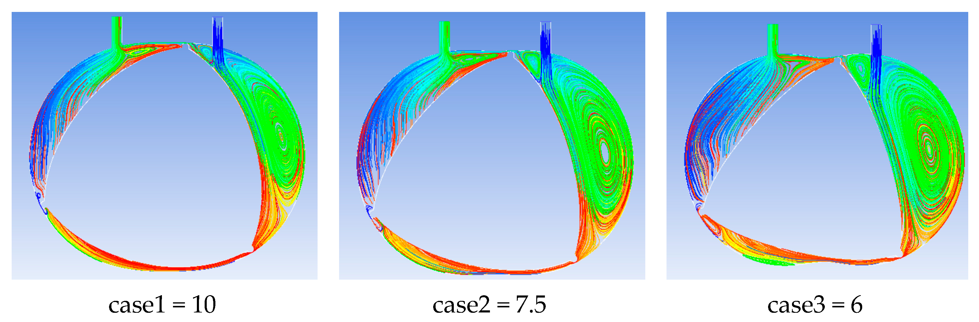
4. Computational Fluid Dynamics Methods

By surveying the literature, CFD methods have been widely used for performance prediction of rotary engines based on flow characteristics including mass flow rate, pressure fluctuations, leakage analysis, vortex statistics, and fluid moment. The simulation of dynamically moving fluid is a challenging task which has been modelled and applied to estimate the flow field in rotary engines [3,47,77,86,99,107,118,119,120,121,122,123,124]. In addition, apex seals must be properly modeled to ensure the gas tightness of separated combustion chambers. Taskiran, et al. solved these problems by using the User Defined Function (UDF) of ANSYS-Fluent that rotates motor eccentrically in a specified speed and enables dynamic mesh motion in the fluid region. Hexahedral and tetrahedral mesh structures were used in the regions of port channels and combustion chambers, respectively [125]. The efficacy of CFD approaches have been validated in previous research and the computational calculations with regards to the flow characteristics of rotary engines are found to be in good agreement with experimental results [126]. Thus, CFD methods are recognized technologies that, to date, allow industries and academia to analyze the advantages and disadvantages of the new developments in rotary engines.

4.1. Dynamic Mesh Generation

Since the computational models include the unsteady fluid flow with moving volume of the working chamber, a dynamic mesh is therefore incorporated into the moving fluid model domains such as the rotating rotor and boundary walls [118,127]. It is important to choose a suitable mesh size for conducting simulation in order to save computational time resource; therefore, this computational method must satisfy the mesh convergence criteria to achieve minimum time required. The mesh size validation study includes two approaches. Initially, the grid independence test is conducted by fixing the time per step while the grid size is varied. The next approach is to fix this grid size achieved in previous approach while time per step will be varied to determine the most accurate time step size. Once the mesh convergence criteria are confirmed, the number of cells, faces, and nodes can be obtained [3,77].

4.2. Operating Conditions

For computational modeling of rotary engine, in the solution of Navier Stokes equations, the pressure implicit splitting of operators (PISO) scheme is used by researchers for pressure velocity coupling; the first order upwind scheme is used for turbulence kinetic energy and turbulence dissipation rate terms, and the second order upwind scheme is to differentiate energy, density, and momentum terms. Since turbulence modeling is important in studying the flow field calculations of the internal combustion engines, RNG (renormalization group) and realizable k-ε turbulence models were tested in validation studies of numerical calculations. Turbulence models (refer to Figure 15) tested on a rotary engine of which flow field was experimentally obtained and published by Fan et al. [118]. Though some researchers still use the standard k-ε model, improved versions of k-ε models were generated for special applications. For example, the RNG k-ε model is well suited to numerical simulations of ICEs, since it has a higher accuracy for vortex flow [128]. The RNG model, in contrast to the normal k-ε turbulence model, contains an effective viscosity component (μeff) and the following extra term (Rε) in the transport equation, which improves numerical simulations. The realizable k- model is a version of the conventional k-ε model that includes a new formulation for defining eddy viscosity and a new transport equation for the dissipation rate [129]. Satisfying certain constraints on Reynolds stresses, the realizable k-ε model offers consistent results with the physics of turbulent flows and more accurately predicts flow fields that have strong streamline curvature, vortices, and rotation [130]. Taskiran et al. [125] assumed air to be at atmospheric pressure at the inlet and outlet boundaries of intake and exhaust channels. A constant temperature of 300 K and no slip conditions were set on the wall boundaries. The results of the RNG and realizable k-ε models are demonstrated in Figure 15. Though both turbulence models present very similar results, the RNG model predicts more accurately the location of rotational flow and velocity vectors. The difference between turbulence models arises at regions close to the walls as seen on trailing side of the rotor.
Hsieh and Cheng [85], in their research, conducted a 3D simulation of an RE by setting the inlet pressure to 2 atmospheric pressure and outlet pressure to 1 atmospheric pressure while the rotation speed was 1800 rpm. It considered a turbulent model (k-ε model) and a clearance constant of 0.15 mm for apex sealing, and captured stream lines and vortex formation for three different chamber designs based on K factors (case1 = 10, case2 = 7.5, case3 = 6), as shown in Figure 16.
Hsieh et al. [77] conducted a 3D CFD analysis using air and hydrogen as fuels to investigate the flow characteristics of RE along with leakage analysis. The rotor speed was set to 1000 rpm, the temperature to 300 K, and the inlet and outlet pressures were set to pressure 2 atm and 1 atm, respectively. The authors found that an excess of leakage occurs at the apex of rotors affecting the engine performance adversely. The stream lines indicating the flow leakage are shown in Figure 17. As the fluid flows from high pressure to low pressure zone while circulating between the chambers, a significant amount of fluid leaks to the peripheral region of the rotor due to the effect of cavity wall and rotor apex. The streamline visuals obtained from three dimensional simulation results give information regarding fluid motion and fluid flow path. The red color streamlines indicate high pressure field and blue color streamlines as low pressure field. Multiple streamlines in red color can be seen at the upper rotor apex which depict that some of the fluid gets discharged without being circulated.

5. Conclusions and Future Prospects

The rotary engine has made important developments in the transport and energy sectors, bringing convenience to human society. However, in order to continue fulfilling a wide range of market demands as an automobile engine, the rotary engine must improve fuel efficiency and exhaust gas pollutions. Targeting mainly improvement in fuel economy and the reduction of exhaust emissions, there are numerous prospects to explore for improvements, including hydrogen enrichment, rotor designs, fuel utilization methods, and the implementation of latest computer software technologies.
Although the rotary engine has several advantages over the reciprocating engine, the high hydrocarbon emissions and low combustion efficiency are two major disadvantages affected by the gas leakage issues. The leaking issue is a significant drawback of the RE, which hinders its commercialization. In addition, the sealing of the rotary engine is more difficult due to the longer sealing line, and the gas sealing system of the rotary engine is much more complicated than that of the reciprocating engine. From a fuel perspective, the hydrogen-powered rotary engine (HRE) has better power density and less risk of backfire compared to gasoline engines, although it has knock problems due to its extended combustion chamber.
Since the design model accuracy influences the fluid flow, leakages, flow path problems to a great extent, any inaccuracy may considerably affect the engine’s efficiency and performance. The deviation function method can therefore be a key aspect to new designs and development for trochoid profiles. The trochoid profiles can be modified using mathematical equations and profile curves derived from traditional designs available in the literature for guidance. Relevant information on different aspects, including ignition timing, spark plug number, spark plug location, excess air ratio, and engine speed, have been provided for the design of hydrogen-specific RE.
The modeling of rotary engines is generally not easy to perform due to its moving boundaries and flow complexity. These technical aspects make the simulation challenging. By employing three-dimensional CFD methods, which includes fluid combustion model and turbulence models, while considering the clearances, gaps, boundary walls, and interacting surfaces of the designed models is a recognized and feasible method to predict the fluid and combustion models close to real prototype rotary engines.
Hence, focusing on the apex seal as a crucial subject, the combustion chamber profile, the rotor profile, and port designs (peripheral and side ported) of REs require an in-depth investigation. Three-dimensional CFD analysis is therefore an instrumental approach to study the pros and cons of new rotary engine designs with respect to leakages, combustion, and fluid flow dynamics. Taking into account port designs with a novel chamber design and various rotor profiles can be key considerations which significantly influence the combustion efficiency, leakages, and flow pattern. The working chamber design can be modified using the trochoid-based models in order to examine the apex sealing condition. The sealing condition can be determined by leakages and streamlines which can be achieved using numerical methods.

Author Contributions

Writing—original draft preparation, T.J.; writing—review and editing, T.J. and C.-F.H.; supervision, C.-F.H. All authors have read and agreed to the published version of the manuscript.

Funding

This research received no external funding.

Data Availability Statement

Not applicable to this article.

Conflicts of Interest

The authors declare no conflict of interest.

References

  1. Kweon, C.-B.M. A Review of Heavy-Fueled Rotary Engine Combustion Technologies; Army Research Lab: Adelphi, MD, USA, 2011. [Google Scholar]
  2. Drbal, M.A. Method of rotary engine performance prediction. Sci. J. Sil. Univ. Technol. Ser. Transp. 2020, 108, 37–43. [Google Scholar] [CrossRef]
  3. Qin, Z.; Jia, M.; Yang, H. Study on vortex characteristics and velocity distribution in small rotary engine. Energy 2020, 206, 118065. [Google Scholar] [CrossRef]
  4. Antonelli, M.; Baccioli, A.; Francesconi, M.; Desideri, U.; Martorano, L. Operating maps of a rotary engine used as an expander for micro-generation with various working fluids. Appl. Energy 2014, 113, 742–750. [Google Scholar] [CrossRef]
  5. Ribau, J.; Silva, C.; Brito, F.P.; Martins, J. Analysis of four-stroke, Wankel, and microturbine based range extenders for electric vehicles. Energy Convers. Manag. 2012, 58, 120–133. [Google Scholar] [CrossRef]
  6. Hsieh, C.-F.F.; Cheng, H.-Y.; Bhoir, M.B.; Tambuskar, D.; Hsieh, C.-F.F.; Yang, J.; Ji, C.; Wang, S.; Wang, D.; Ma, Z.; et al. Numerical investigation on the mixture formation and combustion processes of a gasoline rotary engine with direct injected hydrogen enrichment. Int. J. Hydrogen Energy 2022, 46, 385–397. [Google Scholar] [CrossRef]
  7. Ozcanli, M.; Bas, O.; Akar, M.A.; Yildizhan, S.; Serin, H. Recent studies on hydrogen usage in Wankel SI engine. Int. J. Hydrogen Energy 2018, 43, 18037–18045. [Google Scholar] [CrossRef]
  8. Jewkes, J.; Sawers, D.; Stillerman, R. The Wankel Rotary Piston Engine. In The Sources of Invention; Palgrave Macmillan: London, UK, 1969. [Google Scholar]
  9. Pascale, R.; Rohlen, T.P. The Mazda Turnaround. J. Jpn. Stud. 1983, 9, 219. [Google Scholar] [CrossRef]
  10. Cranswick, M. Mazda Rotary-Engined Cars from Cosmo 110S to RX-8; Veloce Publishing Ltd.: Dorchester, UK, 2016; ISBN 978-1-787116-64-1. [Google Scholar]
  11. Jones, C. An update of applicable automotive engine rotary stratified charge developments. SAE Tech. Pap. 1982, 820347. [Google Scholar] [CrossRef]
  12. Jones, C.; Lamping, H. Curtiss-Wright’s development status of the stratified charge rotating combustion engine. SAE Tech. Pap. 1971, 80, 1956–1980. [Google Scholar] [CrossRef]
  13. Ohkubo, M.; Tashima, S.; Shimizu, R.; Fuse, S.; Ebino, H. Developed technologies of the new rotary engine (RENESIS). In Proceedings of the 2004 SAE World Congress, Detroit, MI, USA, 8–11 March 2004. [Google Scholar] [CrossRef]
  14. German, J. Advanced Propulsion System Studies for General Aviation Aircraft; Williams International: Walled Lake, MI, USA, 2003. [Google Scholar]
  15. Norman, T.J. A Performance Model of a Spark Ignition Wankel Engine: Including the Effects of Crevice Volumes, Gas Leakage, and Heat Transfer. Ph.D. Thesis, University of Massachusetts, Amherst, MA, USA, 1983. Volume 2. [Google Scholar]
  16. Irion, C.E.; Mount, R.E. Stratified Charge Rotary Engine Critical Technology Enablement; Rotary Power International, Inc.: Wood-Ridge, NJ, USA, 1992; Volume I. [Google Scholar]
  17. Roberts, J.M. Heat Release Estimation and Prediction of Wankel Stratified-Charge Combustion Engine. Ph.D. Thesis, University of Pittsburgh, Pittsburgh, PA, USA, 1985. [Google Scholar]
  18. Fu, K.; Knobloch, A.J.; Martinez, F.C.; Walther, D.C.; Fernandez-Pello, C.; Pisano, A.P.; Liepmann, D. Design and fabrication of a silicon-based mems rotary engine. Am. Soc. Mech. Eng. Adv. Energy Syst. Div. AES 2001, 41, 303–308. [Google Scholar]
  19. LEE, C. Design and fabrication of a micro Wankel engine using MEMS technology. Microelectron. Eng. 2004, 73–74, 529–534. [Google Scholar] [CrossRef]
  20. Sprague, S.B.; Park, S.W.; Walther, D.C.; Pisano, A.P.; Fernandez-Pello, A.C. Development and characterisation of small-scale rotary engines. Int. J. Altern. Propuls. 2007, 1, 275–293. [Google Scholar] [CrossRef]
  21. Heller, D.A. International Strategic Alliances and Technology Strategy: The Case of Rotary-Engine Development at Mazda. Econ. Rev. 2005, 52, 31–56. [Google Scholar]
  22. Hosseini, S.E.; Wahid, M.A.; Ganjehkaviri, A. An overview of renewable hydrogen production from thermochemical process of oil palm solid waste in Malaysia. Energy Convers. Manag. 2015, 94, 415–429. [Google Scholar] [CrossRef]
  23. Safari, F.; Dincer, I. A review and comparative evaluation of thermochemical water splitting cycles for hydrogen production. Energy Convers. Manag. 2020, 205, 112182. [Google Scholar] [CrossRef]
  24. Shivaprasad, K.V.; Kumar, G.N.; Guruprasad, K.R. Performance, Emission and Fuel Induction System of Hydrogen Fuel Operated Spark Ignition Engine—A Review. Int. J. Mod. Eng. Res. 2012, 2, 565–571. [Google Scholar]
  25. Fayaz, H.; Saidur, R.; Razali, N.; Anuar, F.S.; Saleman, A.R.; Islam, M.R. An overview of hydrogen as a vehicle fuel. Renew. Sustain. Energy Rev. 2012, 16, 5511–5528. [Google Scholar] [CrossRef]
  26. Shadidi, B.; Najafi, G.; Yusaf, T. A review of hydrogen as a fuel in internal combustion engines. Energies 2021, 14, 6209. [Google Scholar] [CrossRef]
  27. Meng, H.; Ji, C.; Wang, D.; Xin, G.; Chang, K.; Yang, J.; Wang, S. Research on the load control of hydrogen-fueled Wankel rotary engine. Int. J. Hydrogen Energy 2022, 47, 16665–16675. [Google Scholar] [CrossRef]
  28. Gao, J.; Tian, G.; Ma, C.; Balasubramanian, D.; Xing, S.; Jenner, P. Numerical investigations of combustion and emissions characteristics of a novel small scale opposed rotary piston engine fuelled with hydrogen at wide open throttle and stoichiometric conditions. Energy Convers. Manag. 2020, 221, 113178. [Google Scholar] [CrossRef]
  29. Gao, J.; Xing, S.; Tian, G.; Ma, C.; Zhao, M.; Jenner, P. Numerical simulation on the combustion and NOx emission characteristics of a turbocharged opposed rotary piston engine fuelled with hydrogen under wide open throttle conditions. Fuel 2021, 285, 119210. [Google Scholar] [CrossRef]
  30. Meng, H.; Ji, C.; Yang, J.; Wang, S.; Xin, G.; Chang, K.; Wang, H. Experimentally investigating the asynchronous ignition on a hydrogen-fueled Wankel rotary engine. Fuel 2022, 312, 122988. [Google Scholar] [CrossRef]
  31. Vadlamudi, S.; Gugulothu, S.K.; Panda, J.K.; Deepanraj, B.; Kumar, P.R.V. Paradigm analysis of performance and exhaust emissions in CRDI engine powered with hydrogen and Hydrogen/CNG fuels: A green fuel approach under different injection strategies. Int. J. Hydrogen Energy 2022, in press. [Google Scholar] [CrossRef]
  32. Abdalla, A.M.; Hossain, S.; Nisfindy, O.B.; Azad, A.T.; Dawood, M.; Azad, A.K. Hydrogen production, storage, transportation and key challenges with applications: A review. Energy Convers. Manag. 2018, 165, 602–627. [Google Scholar] [CrossRef]
  33. Hosseini, S.E.; Butler, B. An overview of development and challenges in hydrogen powered vehicles. Int. J. Green Energy 2020, 17, 13–37. [Google Scholar] [CrossRef] [Green Version]
  34. Sun, Z.Y.; Li, G.X. On reliability and flexibility of sustainable energy application route for vehicles in China. Renew. Sustain. Energy Rev. 2015, 51, 830–846. [Google Scholar] [CrossRef]
  35. Matthias, N.S.; Wallner, T.; Scarcelli, R. A Hydrogen Direct Injection Engine Concept that Exceeds U.S. DOE Light-Duty Efficiency Targets. SAE Int. J. Engines 2012, 5, 838–849. [Google Scholar] [CrossRef]
  36. Boretti, A. Hydrogen internal combustion engines to 2030. Int. J. Hydrogen Energy 2020, 45, 23692–23703. [Google Scholar] [CrossRef]
  37. Naganuma, K.; Yamane, K.; Takagi, Y.; Kawamura, A.; Yanai, T.; Sato, Y. Summary and Progress of the Hydrogen ICE Truck Development Project. SAE Int. J. Commer. Veh. 2009, 2, 110–117. [Google Scholar]
  38. Meng, H.; Ji, C.; Yang, J.; Wang, S.; Chang, K.; Xin, G. Experimental study of the effects of excess air ratio on combustion and emission characteristics of the hydrogen-fueled rotary engine. Int. J. Hydrogen Energy 2021, 46, 32261–32272. [Google Scholar] [CrossRef]
  39. Wang, D.; Ji, C.; Wang, S.; Yang, J.; Wang, Z. Numerical study of the premixed ammonia-hydrogen combustion under engine-relevant conditions. Int. J. Hydrogen Energy 2021, 46, 2667–2683. [Google Scholar] [CrossRef]
  40. Dhyani, V.; Subramanian, K.A. Control of backfire and NOx emission reduction in a hydrogen fueled multi-cylinder spark ignition engine using cooled EGR and water injection strategies. Int. J. Hydrogen Energy 2019, 44, 6287–6298. [Google Scholar] [CrossRef]
  41. Gao, J.; Wang, X.; Song, P.; Tian, G.; Ma, C. Review of the backfire occurrences and control strategies for port hydrogen injection internal combustion engines. Fuel 2022, 307, 121553. [Google Scholar] [CrossRef]
  42. Gong, C.; Si, X.; Liu, F. Combined effects of excess air ratio and EGR rate on combustion and emissions behaviors of a GDI engine with CO2 as simulated EGR (CO2) at low load. Fuel 2021, 293, 120442. [Google Scholar] [CrossRef]
  43. Yip, H.L.; Srna, A.; Yuen, A.C.Y.; Kook, S.; Taylor, R.A.; Yeoh, G.H.; Medwell, P.R.; Chan, Q.N. A review of hydrogen direct injection for internal combustion engines: Towards carbon-free combustion. Appl. Sci. 2019, 9, 4842. [Google Scholar] [CrossRef] [Green Version]
  44. Gürbüz, H.; Akçay, İ.H. Evaluating the effects of boosting intake-air pressure on the performance and environmental-economic indicators in a hydrogen-fueled SI engine. Int. J. Hydrogen Energy 2021, 46, 28801–28810. [Google Scholar] [CrossRef]
  45. Ji, C.; Meng, H.; Wang, S.; Wang, D.; Yang, J.; Shi, C.; Ma, Z. Realizing stratified mixtures distribution in a hydrogen-enriched gasoline Wankel engine by different compound intake methods. Energy Convers. Manag. 2020, 203, 112230. [Google Scholar] [CrossRef]
  46. Shi, C.; Zhang, Z.; Ji, C.; Li, X.; Di, L.; Wu, Z. Potential improvement in combustion and pollutant emissions of a hydrogen-enriched rotary engine by using novel recess configuration. Chemosphere 2022, 299, 134491. [Google Scholar] [CrossRef]
  47. Wang, H.; Ji, C.; Su, T.; Shi, C.; Ge, Y.; Yang, J.; Wang, S. Comparison and implementation of machine learning models for predicting the combustion phases of hydrogen-enriched Wankel rotary engines. Fuel 2022, 310, 122371. [Google Scholar] [CrossRef]
  48. Su, T.; Ji, C.; Wang, S.; Shi, L.; Yang, J.; Cong, X. Idle performance of a hydrogen rotary engine at different excess air ratios. Int. J. Hydrogen Energy 2018, 43, 2443–2451. [Google Scholar] [CrossRef]
  49. Yang, J.; Meng, H.; Ji, C.; Wang, S. Comparatively investigating the leading and trailing spark plug on the hydrogen rotary engine. Fuel 2022, 308, 122005. [Google Scholar] [CrossRef]
  50. Meng, H.; Ji, C.; Xin, G.; Yang, J.; Chang, K.; Wang, S. Comparison of combustion, emission and abnormal combustion of hydrogen-fueled Wankel rotary engine and reciprocating piston engine. Fuel 2022, 318, 123675. [Google Scholar] [CrossRef]
  51. Meng, H.; Ji, C.; Su, T.; Yang, J.; Chang, K.; Xin, G.; Wang, S. Analyzing characteristics of knock in a hydrogen-fueled Wankel rotary engine. Energy 2022, 250, 123828. [Google Scholar] [CrossRef]
  52. Marchenko, O.V.; Solomin, S.V. The future energy: Hydrogen versus electricity. Int. J. Hydrogen Energy 2015, 40, 3801–3805. [Google Scholar] [CrossRef]
  53. Muradov, N.Z.; Veziroǧlu, T.N. “Green” path from fossil-based to hydrogen economy: An overview of carbon-neutral technologies. Int. J. Hydrogen Energy 2008, 33, 6804–6839. [Google Scholar] [CrossRef]
  54. Durbin, D.J.; Malardier-Jugroot, C. Review of hydrogen storage techniques for on board vehicle applications. Int. J. Hydrogen Energy 2013, 38, 14595–14617. [Google Scholar] [CrossRef]
  55. Kaur, M.; Pal, K. Review on hydrogen storage materials and methods from an electrochemical viewpoint. J. Energy Storage 2019, 23, 234–249. [Google Scholar] [CrossRef]
  56. Mohtasham, J. Review Article-Renewable Energies. Energy Procedia 2015, 74, 1289–1297. [Google Scholar] [CrossRef] [Green Version]
  57. Shi, H.; Uddeen, K.; An, Y.; Pei, Y.; Johansson, B. Statistical study on engine knock oscillation and heat release using multiple spark plugs and pressure sensors. Fuel 2021, 297, 120746. [Google Scholar] [CrossRef]
  58. Shi, H.; Uddeen, K.; An, Y.; Pei, Y.; Johansson, B. Multiple spark plugs coupled with pressure sensors: A new approach for knock mechanism study on SI engines. Energy 2021, 227, 120382. [Google Scholar] [CrossRef]
  59. Dhyani, V.; Subramanian, K.A. Experimental investigation on effects of knocking on backfire and its control in a hydrogen fueled spark ignition engine. Int. J. Hydrogen Energy 2018, 43, 7169–7178. [Google Scholar] [CrossRef]
  60. Szwaja, S. Knock and combustion rate interaction in a hydrogen fuelled combustion engine. J. KONES 2011, 18, 431–438. [Google Scholar]
  61. Szwaja, S.; Naber, J.D. Dual nature of hydrogen combustion knock. Int. J. Hydrogen Energy 2013, 38, 12489–12496. [Google Scholar] [CrossRef]
  62. Li, Y.; Gao, W.; Li, Y.; Fu, Z.; Zou, J. Numerical investigation on combustion and knock formation mechanism of hydrogen direct injection engine. Fuel 2022, 316, 123302. [Google Scholar] [CrossRef]
  63. Salvi, B.L.; Subramanian, K.A. Experimental investigation on effects of exhaust gas recirculation on flame kernel growth rate in a hydrogen fuelled spark ignition engine. Appl. Therm. Eng. 2016, 107, 48–54. [Google Scholar] [CrossRef]
  64. Szwaja, S.; Cupiał, K.; Grab-Rogaliński, K. Anomalies in Combustion of Hydrogen in a Si Engine Modified to Work as a Supercharged One. J. KONES. Powertrain Transp. 2015, 19, 437–442. [Google Scholar] [CrossRef]
  65. Chen, W.; Yu, S.; Zuo, Q.; Zhu, G.; Zhang, B.; Yang, X. Combined Effect of Air Intake Method and Hydrogen Injection Timing on Airflow Movement and Mixture Formation in a hydrogen direct injection rotary engine. Int. J. Hydrogen Energy 2022, 47, 12739–12758. [Google Scholar] [CrossRef]
  66. Zou, R.; Liu, J.; Jiao, H.; Wang, N.; Zhao, J. Numerical study on auto-ignition development and knocking characteristics of a downsized rotary engine under different inlet pressures. Fuel 2022, 309, 122046. [Google Scholar] [CrossRef]
  67. Yang, J.; Ji, C.; Wang, S.; Shi, C.; Wang, D.; Ma, Z.; Yang, Z. Numerical study of compound intake on mixture formation and combustion process in a hydrogen-enriched gasoline Wankel rotary engine. Energy Convers. Manag. 2019, 185, 66–74. [Google Scholar] [CrossRef]
  68. Yang, Z.; Ji, C.; Huang, X.; Yang, J.; Wang, H.; Wang, S. Modeling and analysis of apex seal leakage in a hydrogen fueled Wankel rotary engine. Fuel 2023, 331, 125848. [Google Scholar] [CrossRef]
  69. Picard, M.; Tian, T.; Nishino, T. Predicting Gas Leakage in the Rotary Engine-Part I: Apex and Corner Seal. J. Eng. Gas Turbines Power 2016, 138, 062503. [Google Scholar] [CrossRef]
  70. Picard, M.; Tian, T.; Nishino, T. Predicting Gas Leakage in the Rotary Engine-Part II: Side Seals and Summary. J. Eng. Gas Turbines Power 2016, 138, 062504. [Google Scholar] [CrossRef]
  71. Fan, B.; Zeng, Y.; Pan, J.; Fang, J.; Hammed, A.S.; Wang, Y. Evaluation and analysis of injection strategy in a peripheral ported rotary engine fueled with natural gas/hydrogen blends under the action of apex seal leakage. Fuel 2022, 310, 122315. [Google Scholar] [CrossRef]
  72. Fan, B.; Wang, Y.; Zhang, Y.; Pan, J.; Yang, W.; Zeng, Y. Numerical Investigation on the Combustion Performance of a Natural Gas/Hydrogen Dual Fuel Rotary Engine under the Action of Apex Seal Leakage. Energy Fuels 2021, 35, 770–784. [Google Scholar] [CrossRef]
  73. Fan, B.; Zeng, Y.; Pan, J.; Fang, J.; Salami, H.A.; Wang, Y. Numerical study of injection strategy on the combustion process in a peripheral ported rotary engine fueled with natural gas/hydrogen blends under the action of apex seal leakage. Energy 2022, 242, 122532. [Google Scholar] [CrossRef]
  74. Fan, B.; Zeng, Y.; Zhang, Y.; Pan, J.; Yang, W.; Wang, Y. Research on the hydrogen injection strategy of a direct injection natural gas/hydrogen rotary engine considering apex seal leakage. Int. J. Hydrogen Energy 2021, 46, 9234–9251. [Google Scholar] [CrossRef]
  75. Wang, H.; Ji, C.; Shi, C.; Ge, Y.; Meng, H.; Yang, J.; Chang, K.; Yang, Z.; Wang, S.; Wang, X. Modeling and parametric study of the performance-emissions trade-off of a hydrogen Wankel rotary engine. Fuel 2022, 318, 123662. [Google Scholar] [CrossRef]
  76. Wang, W.; Zuo, Z.; Liu, J. Miniaturization limitations of rotary internal combustion engines. Energy Convers. Manag. 2016, 112, 101–114. [Google Scholar] [CrossRef]
  77. Hsieh, C.F.; Chen, K.T.; Johar, T. Fluid flow characteristics of two types rotary engines. Int. J. Hydrogen Energy 2021, 46, 40154–40174. [Google Scholar] [CrossRef]
  78. Zhang, S.; Liu, J.; Zuo, Z.; Zhang, Y. An analytical investigation of oil film thickness for the apex seal in a small Wankel rotary engine. Tribol. Int. 2017, 116, 383–393. [Google Scholar] [CrossRef]
  79. Harikrishnan, T.V.; Challa, S.; Radhakrishna, D. Numerical Investigation on the Effects of Flame Propagation in Rotary Engine Performance with Leakage and Different Recess Shapes Using Three-Dimensional Computational Fluid Dynamics. J. Energy Resour. Technol. Trans. ASME 2016, 138, 052210. [Google Scholar] [CrossRef]
  80. Hwang, P.W.; Chen, X.C.; Cheng, H.C. Influences of Ignition Timing, Spark Plug and Intake Port Locations on the Combustion Performance of a Simulated Rotary Engine. J. Mech. 2016, 32, 579–591. [Google Scholar] [CrossRef]
  81. Bagnell, M. (12) Patent Application Publication (10). U.S. Patent 2017/0167368 A1, 18 May 2017. [Google Scholar]
  82. Warren, S.; Yang, D.C.H. Design of rotary engines from the apex seal profile (Abbr.: Rotary engine design by apex seal). Mech. Mach. Theory 2013, 64, 200–209. [Google Scholar] [CrossRef]
  83. Rose, S.W.; Yang, D.C.H. Wide and multiple apex seals for the rotary engine: (Abbr.: Multi-Apex-Seals for the Rotary Engine). Mech. Mach. Theory 2014, 74, 202–215. [Google Scholar] [CrossRef]
  84. Rose, S.W.; Yang, D.C.H. The Deviation Function Method of Rotary Engine Design by Geometric Parameters. J. Mech. Des. 2014, 136, 051004. [Google Scholar] [CrossRef]
  85. Hsieh, C.-F.; Cheng, H.-Y. Effects of Various Geometric Designs on the Flow Characteristics of a Triangular Rotary Engine. Mech. Eng. Res. 2015, 5, 1–11. [Google Scholar] [CrossRef]
  86. Bhoir, M.B.; Tambuskar, D. Analysis of Wankel Rotary Engine using Deviation Function for Performance Improvement. Int. J. Interdiscip. Innov. Res. Dev. 2017, 2, 25–31. [Google Scholar]
  87. Hsieh, C.F. Dynamics analysis of the triangular rotary engine structures. J. Eng. Gas Turbines Power 2018, 140, 112804. [Google Scholar] [CrossRef]
  88. Yang, J.; Ji, C.; Wang, S.; Wang, D.; Shi, C.; Ma, Z.; Zhang, B. Numerical study of hydrogen direct injection strategy on mixture formation and combustion process in a partially premixed gasoline Wankel rotary engine. Energy Convers. Manag. 2018, 176, 184–193. [Google Scholar] [CrossRef]
  89. Amrouche, F.; Erickson, P.A.; Varnhagen, S.; Park, J.W. An experimental analysis of hydrogen enrichment on combustion characteristics of a gasoline Wankel engine at full load and lean burn regime. Int. J. Hydrogen Energy 2018, 43, 19250–19259. [Google Scholar] [CrossRef]
  90. Amrouche, F.; Erickson, P.A.; Varnhagen, S.; Park, J.W. An experimental study of a hydrogen-enriched ethanol fueled Wankel rotary engine at ultra lean and full load conditions. Energy Convers. Manag. 2016, 123, 174–184. [Google Scholar] [CrossRef]
  91. Sadiq, G.A.; Al-Dadah, R.; Mahmoud, S. Development of rotary Wankel devices for hybrid automotive applications. Energy Convers. Manag. 2019, 202, 112159. [Google Scholar] [CrossRef]
  92. Amrouche, F.; Erickson, P.A.; Park, J.W.; Varnhagen, S. Extending the lean operation limit of a gasoline Wankel rotary engine using hydrogen enrichment. Int. J. Hydrogen Energy 2016, 41, 14261–14271. [Google Scholar] [CrossRef]
  93. Fan, B.; Wang, J.; Pan, J.; Zeng, Y.; Fang, J.; Lu, Q.; Wu, X.; Chen, W.; Qi, X. Computational study of hydrogen injection strategy on the combustion performance of a direct injection rotary engine fueled with natural gas/hydrogen blends. Fuel 2022, 328, 125190. [Google Scholar] [CrossRef]
  94. Pan, J.; Chen, W.; Yang, W.; Xiao, M.; Zhu, Y.; Fan, B. Effects of intake and exhaust valve timing on the performance of an air-powered rotary engine. Environ. Prog. Sustain. Energy 2018, 37, 1462–1474. [Google Scholar] [CrossRef]
  95. Fan, B.; Pan, J.; Yang, W.; Chen, W.; Bani, S. The influence of injection strategy on mixture formation and combustion process in a direct injection natural gas rotary engine. Appl. Energy 2017, 187, 663–674. [Google Scholar] [CrossRef]
  96. Chen, W.; Pan, J.; Liu, Y.; Fan, B.; Liu, H.; Otchere, P. Numerical investigation of direct injection stratified charge combustion in a natural gas-diesel rotary engine. Appl. Energy 2019, 233–234, 453–467. [Google Scholar] [CrossRef]
  97. Yang, J.; Ji, C.; Wang, S.; Wang, D.; Ma, Z.; Ma, L. A comparative study of mixture formation and combustion processes in a gasoline Wankel rotary engine with hydrogen port and direct injection enrichment. Energy Convers. Manag. 2018, 168, 21–31. [Google Scholar] [CrossRef]
  98. Otchere, P.; Pan, J.; Fan, B.; Chen, W.; Lu, Y.; Jianxing, L. Mixture formation and combustion process of a biodiesel fueled direct injection rotary engine (DIRE) considering injection timing, spark timing and equivalence ratio—CFD study. Energy Convers. Manag. 2020, 217, 112948. [Google Scholar] [CrossRef]
  99. Chen, W.; Pan, J.; Fan, B.; Otchere, P.; Miao, N.; Lu, Y. Numerical investigation of dual-fuel injection timing on air-fuel mixing and combustion process in a novel natural gas-diesel rotary engine. Energy Convers. Manag. 2018, 176, 334–348. [Google Scholar] [CrossRef]
  100. Zambalov, S.D.; Yakovlev, I.A.; Maznoy, A.S. Effect of multiple fuel injection strategies on mixture formation and combustion in a hydrogen-fueled rotary range extender for battery electric vehicles. Energy Convers. Manag. 2020, 220, 113097. [Google Scholar] [CrossRef]
  101. Ji, C.; Chang, K.; Wang, S.; Yang, J.; Wang, D.; Meng, H.; Wang, H. Effect of injection strategy on the mixture formation and combustion process in a gasoline direct injection rotary engine. Fuel 2021, 304, 121428. [Google Scholar] [CrossRef]
  102. Zou, R.; Liu, J.; Wang, N.; Jiao, H. Combined effects of intake oxygen enrichment, intake pressure and temperature on combustion behavior and emission characteristics of a small-scaled rotary engine. Appl. Therm. Eng. 2022, 207, 118096. [Google Scholar] [CrossRef]
  103. Chang, K.; Ji, C.; Wang, S.; Yang, J.; Meng, H.; Wang, H.; Xin, G. Comparative study on different spark plug positions of a rotary engine with gasoline port and direct injection. Fuel 2022, 310, 122376. [Google Scholar] [CrossRef]
  104. Deng, X.; Feng, Z.; Lei, J.; Liu, Y.; Jia, D. Influence of Intake Pipe Deflection Angle on In-Cylinder Flow and Combustion Characteristics of a Rotary Engine. J. Energy Resour. Technol. Trans. ASME 2022, 144, 082302. [Google Scholar] [CrossRef]
  105. Wang, H.; Ji, C.; Shi, C.; Wang, S.; Yang, J.; Ge, Y. Investigation of the gas injection rate shape on combustion, knock and emissions behavior of a rotary engine with hydrogen direct-injection enrichment. Int. J. Hydrogen Energy 2021, 46, 14790–14804. [Google Scholar] [CrossRef]
  106. Jiao, H.; Zou, R.; Wang, N.; Luo, B.; Pan, W.; Liu, J. Optimization design of the ignition system for Wankel rotary engine considering ignition environment, flow, and combustion. Appl. Therm. Eng. 2022, 201, 117713. [Google Scholar] [CrossRef]
  107. Zambalov, S.D.; Yakovlev, I.A.; Skripnyak, V.A. Numerical simulation of hydrogen combustion process in rotary engine with laser ignition system. Int. J. Hydrogen Energy 2017, 42, 17251–17259. [Google Scholar] [CrossRef]
  108. Taskiran, O.O. Improving burning speed by using hydrogen enrichment and turbulent jet ignition system in a rotary engine. Int. J. Hydrogen Energy 2021, 46, 29649–29662. [Google Scholar] [CrossRef]
  109. Ma, D.S.; Sun, Z.Y. Progress on the studies about NOx emission in PFI-H2ICE. Int. J. Hydrogen Energy 2020, 45, 10580–10591. [Google Scholar] [CrossRef]
  110. Galloni, E.; Fontana, G.; Palmaccio, R. Effects of exhaust gas recycle in a downsized gasoline engine. Appl. Energy 2013, 105, 99–107. [Google Scholar] [CrossRef]
  111. Gong, C.; Si, X.; Liu, F. Comparative analysis on combustion and emissions between CO2 and EGR dilution GDI engine at half-load, stoichiometric and lean-burn conditions. Fuel 2022, 309, 122216. [Google Scholar] [CrossRef]
  112. Gong, C.; Si, X.; Liu, F. Combustion and emissions behaviors of a stoichiometric GDI engine with simulated EGR (CO2) at low load and different spark timings. Fuel 2021, 295, 120614. [Google Scholar] [CrossRef]
  113. Zhen, X.; Wang, Y.; Xu, S.; Zhu, Y.; Tao, C.; Xu, T.; Song, M. The engine knock analysis—An overview. Appl. Energy 2012, 92, 628–636. [Google Scholar] [CrossRef]
  114. Verhelst, S.; Maesschalck, P.; Rombaut, N.; Sierens, R. Increasing the power output of hydrogen internal combustion engines by means of supercharging and exhaust gas recirculation. Int. J. Hydrogen Energy 2009, 34, 4406–4412. [Google Scholar] [CrossRef]
  115. Fontana, G.; Galloni, E. Experimental analysis of a spark-ignition engine using exhaust gas recycle at WOT operation. Appl. Energy 2010, 87, 2187–2193. [Google Scholar] [CrossRef]
  116. Chaichan, M. EGR effects on hydrogen engines performance and emissions. Int. J. Sci. Eng. Res. 2016, 7, 80–90. [Google Scholar]
  117. Safari, H.; Jazayeri, S.A.; Ebrahimi, R. Potentials of NOX emission reduction methods in SI hydrogen engines: Simulation study. Int. J. Hydrogen Energy 2009, 34, 1015–1025. [Google Scholar] [CrossRef]
  118. Fan, B.; Pan, J.; Tang, A.; Pan, Z.; Zhu, Y.; Xue, H. Experimental and numerical investigation of the fluid flow in a side-ported rotary engine. Energy Convers. Manag. 2015, 95, 385–397. [Google Scholar] [CrossRef]
  119. Fan, B.; Zhang, Y.; Pan, J.; Liu, Y.; Chen, W.; Otchere, P.; Wei, A.; He, R. The influence of hydrogen injection strategy on mixture formation and combustion process in a port injection (PI) rotary engine fueled with natural gas/hydrogen blends. Energy Convers. Manag. 2018, 173, 527–538. [Google Scholar] [CrossRef]
  120. Fan, B.; Pan, J.; Liu, Y.; Zhu, Y.; Pan, Z.; Chen, W.; Otchere, P. Effect of hydrogen injection strategies on mixture formation and combustion process in a hydrogen direct injection plus natural gas port injection rotary engine. Energy Convers. Manag. 2018, 160, 150–164. [Google Scholar] [CrossRef]
  121. Sadiq, G.A.; Tozer, G.; Al-Dadah, R.; Mahmoud, S. CFD simulations of compressed air two stage rotary Wankel expander—Parametric analysis. Energy Convers. Manag. 2017, 142, 42–52. [Google Scholar] [CrossRef]
  122. Babayev, R.; Andersson, A.; Dalmau, A.S.; Im, H.G.; Johansson, B. Computational characterization of hydrogen direct injection and nonpremixed combustion in a compression-ignition engine. Int. J. Hydrogen Energy 2021, 46, 18678–18696. [Google Scholar] [CrossRef]
  123. TASKIRAN, O.O. Fuel-air mixing process of low pressure direct injection in a side ported rotary engine. Int. J. Automot. Eng. Technol. 2019, 8, 186–194. [Google Scholar] [CrossRef]
  124. Jiao, H.; Ye, X.; Zou, R.; Wang, N.; Liu, J. Comparative study on ignition and combustion between conventional spark-ignition method and near-wall surface ignition method for small-scale Wankel rotary engine. Energy 2022, 255, 124500. [Google Scholar] [CrossRef]
  125. Taskiran, O.O.; Calik, A.T.; Akin Kutlar, O. Comparison of flow field and combustion in single and double side ported rotary engine. Fuel 2019, 254, 115651. [Google Scholar] [CrossRef]
  126. Lee, C.-E.; Yu, H.; Kim, D.; Park, T. Validation of CFD Analysis and Flow Characteristics of GP3 Rotary Engine at Motoring Condition. J. Korean Soc. Combust. 2020, 25, 11–20. [Google Scholar] [CrossRef]
  127. Fan, B.W.; Pan, J.F.; Pan, Z.H.; Tang, A.K.; Zhu, Y.J.; Xue, H. Effects of pocket shape and ignition slot locations on the combustion processes of a rotary engine fueled with natural gas. Appl. Therm. Eng. 2015, 89, 11–27. [Google Scholar] [CrossRef]
  128. Yang, X.; Gupta, S.; Kuo, T.W.; Gopalakrishnan, V. RANS and large Eddy simulation of internal combustion engine flows-A comparative study. J. Eng. Gas Turbines Power 2014, 136, 051507. [Google Scholar] [CrossRef]
  129. Suryan, A.; Kim, H.D.; Setoguchi, T. Comparative study of turbulence models performance for refueling of compressed hydrogen tanks. Int. J. Hydrogen Energy 2013, 38, 9562–9569. [Google Scholar] [CrossRef]
  130. Argyropoulos, C.D.; Markatos, N.C. Recent advances on the numerical modelling of turbulent flows. Appl. Math. Model. 2015, 39, 693–732. [Google Scholar] [CrossRef]
Figure 1. Diagram of the hydrogen-fueled RE (Ozcanli et al. [7]).
Energies 16 00607 g001
Figure 2. Occurrence of backfire and knocking (Dhyani et al. [59]).
Energies 16 00607 g002
Figure 3. Comparison between weak knock and strong knock (Szwaja and Naber [61]). (a) the pressure pulsations start at 0°. (b) indicates pressure pulsation condition during combustion at CR = 12.
Energies 16 00607 g003
Figure 4. Knock intensity for 95th percentile of peak pressure vs. maximum rate of mass fraction burnt at various compression ratios (Szwaja [60]).
Energies 16 00607 g004
Figure 5. Flame speed at various hydrogen mass fractions in relation to equivalence ratios (Yang et al. [67]).
Energies 16 00607 g005
Figure 6. Schematic diagram of corner seal (Picard et al. [69]).
Energies 16 00607 g006
Figure 7. Sealing leakage estimation (Picard et al. [70]).
Energies 16 00607 g007
Figure 8. Apex seal leakage between adjacent combustion chambers (Fan et al. [74]).
Energies 16 00607 g008
Figure 9. Pressure distribution at various engine speeds (Zhang et al. [78]).
Energies 16 00607 g009
Figure 10. Temperature distribution at various spark plug positions (Hwang et al. [80]).
Energies 16 00607 g010
Figure 11. Deviation-function method (Warren and Yang [82]).
Energies 16 00607 g011
Figure 12. Design results of K factor for the rotary engine (Hsieh and Cheng [85]).
Energies 16 00607 g012
Figure 13. Design results of theoretical profile (Hsieh [87]).
Energies 16 00607 g013
Figure 14. Comparison of knock index for different types of injection rate shapes (Wang et al. [105]).
Energies 16 00607 g014
Figure 15. Comparison of RNG and Realizable k-ε models (Taskiran et al. [125]).
Energies 16 00607 g015
Figure 16. Stream lines of the three cases and vortex formation (Hsieh and Cheng [85]).
Energies 16 00607 g016
Figure 17. Stream lines showing leakages at the apex seal (Hsieh et al. [66]).
Energies 16 00607 g017
Disclaimer/Publisher’s Note: The statements, opinions and data contained in all publications are solely those of the individual author(s) and contributor(s) and not of MDPI and/or the editor(s). MDPI and/or the editor(s) disclaim responsibility for any injury to people or property resulting from any ideas, methods, instructions or products referred to in the content.

