1. Introduction
Photovoltaic (PV) systems are popular because they are environmentally friendly, quiet, easy to integrate, suitable for individual or commercial use, have low maintenance costs, and have nonmoving parts [
1]. Concentrated photovoltaic (CPV) technology has become an attractive option to minimize the PV area and increase the amount of solar radiation. Thus, a potentially much lower specific cost is obtained compared with flat photovoltaic/thermal (PVT) collectors [
2]. Bernardo et al. [
3] carried out the implementation of a parabolic corrugated-triangular design of a concentrated photovoltaic/thermal (CPVT) system and a simulation study for three different locations. It was concluded that the CPVT system produced between 3.6 and 4.4 times more electricity compared with the conventional PV system for three different locations. Bahaidarah et al. [
4] reviewed the studies on the homogeneous cooling of PV and CPV technologies. It was reported that current inconsistency, hot spot formation, and thermal stress are caused by high temperatures and nonhomogeneous cooling. This leads to permanent damage of the PV modules and decreased efficiency. There are two important parameters that affect the performance of PV modules, namely solar radiation and the module’s temperature. An increase in the solar radiation improves the electricity production. However, increasing the module’s temperature will be harmful for the PV material [
5]. Therefore, PV cells must be cooled to reduce the operating temperature, prevent damage, and increase efficiency [
3]. For this purpose, some methods, which include refrigerants, thermoelectric modules, and phase change materials, have been used [
6]. The refrigerant method was used in this study.
Heat exchangers with a working fluid (water, oils, refrigerants, nanofluids, etc.) are very popular in concentrated solar systems with triangular parabolic corrugations to utilize thermal energy. Sharaf and Orhan [
7,
8] concluded that the effects of a nonhomogeneous, uneven temperature distribution on the spatial and spectral conditions were an overlooked design issue in CPVT systems. It was pointed out that multi-junction PV modules, micro-channel heat exchangers, and nanoparticle heat transfer fluids (HTFs) were appropriate for CPVT systems and must be encouraged. Simulation studies of a CPVT solar collector with a parabolic trough were performed by Calise and Vanoli [
9], Calise et al. [
2], and Buonomano et al. [
10]. Herez et al. [
11] theoretically investigated the effects of four parameters on the electrical and thermal efficiency of a photovoltaic/thermal hybrid system with a triangular parabolic trough. These parameters were the Reynolds number, the side length of the receiver, the length of the receiver’s tube, and the absorber’s thickness. To maximize electrical efficiency, the Reynolds number must be increased while the side length of the receiver must be decreased. The other parameters did not have a significant effect on the system’s performance. When the side length was 0.03 m and the Reynolds number was 10,000, the electrical efficiencies were 23.24% and 24.87%, respectively. Valizadeh et al. [
12] carried out an energy and exergy analysis of photovoltaic thermal collectors with triangular parabolic troughs through simulations. In order to protect the triangular trough from the external environmental conditions, it was placed between the glass cover and the reflector. Increasing the fluid’s velocity, the channel’s diameter, and the incident radiation increased the electrical efficiency by 1.05%, 3.9%, and 6.6%, respectively. Increasing the fluid’s velocity, the receiver’s width, the channel’s diameter, and the ambient temperature increased the thermal efficiency by 2.2%, 9.4%, 2.75%, and 5.1%, respectively. The maximum exergy efficiency was found to be 30.3%. Deymi-Dashtebayaz et al. [
13] created a new CPVT-HP hybrid system that was modeled in Iranian conditions. The theoretical model was confirmed by the experimental results of Karathanassis et al. [
14]. The energy, exergy, and electrical efficiencies of the hybrid system were calculated. The effects of the nanofluid and porous surfaces on the performance of the CPVT system were also investigated with the CFD program. In the model, the heat taken from the collector was used in the evaporator, and the heat taken from the condenser was used for heating the building. The energy and exergy efficiencies of the CPVT-HP system changed by 62–73% and 32–64%, respectively. The electrical efficiency of the CPVT system ranged from 18.8% to 19.7%. Bamisile et al. [
15] investigated a comprehensive energy system with three renewable energy sources and four scenarios with an energy–exergy approach. Wind, CPVT, and biomass were used. Four different scenarios, namely CPVT/biogas, wind/biogas, CPVT/wind, and biogas only, were compared. The exergy and energy efficiencies of the CPVT system were 59.3% and 74.42%, respectively. Tripathi and Tiwari [
16] theoretically calculated the carbon credits, carbon mitigation, lifecycle costs, and energy payback time of a CPVT system with Matlab. Two HTF systems, namely water (Case 1) and air (Case 2), were used for the baking process and space heating. The number of collectors was determined to be 10 because the outlet’s heating fluid temperature did not change after this number. The annual electrical gain, overall thermal energy, and exergy of the system in Case 1 were 1.04, 2.75, and 2.14 times higher than in Case 2, respectively. Karathanassis et al. [
17] calculated the long-term energetic and exergetic performance of a CPVT system with a dynamic theoretical model. The results were validated with the previous experimental data of the prototype. It was indicated that when the values of the optical efficiency and electrical efficiency were 0.75 and 0.25, respectively, the exergetic efficiency of the system increased from 12% to 24%.
Srivastava and Reddy [
18] numerically and experimentally analyzed the thermal and electrical performance of a linear parabolic trough embodied with a CPV string. A compound parabolic collector (CPC) was used as a secondary reflector to homogenize the flux. The maximum electrical efficiency and electrical output were 20.88% and 692.2 W, respectively, for three cells without CPC and Al
2O
3/water φ = 1%. The maximum thermal efficiency and thermal output were 78.2% and 2592.42 W, respectively, for two cells without CPC and Syltherm-800. It was concluded that the nanofluid had a better heat transfer performance compared with the synthetic fluid, but the synthetic fluid was more reliable and did not cause agglomeration problems. Energy, exergy, and enviro-economic analyses of concentrated PVT systems were performed in a few studies [
19,
20]. Zuhur and Ceylan [
19] designed and tested a concentrated photovoltaic panel/collector system for winter conditions. The theoretical concentration ratio was 3. The photovoltaic panel’s efficiency was about 12% for the nonconcentrated PVT system and about 10% for the concentrated PVT system. The thermal and electrical energy gain of the concentrated PVT system was higher than that of the nonconcentrated PVT system. CO
2 mitigation was increased by 50% by the concentrated PVT system. The exergy efficiency of the system was between 11% and 12%. Zuhur et al. [
20] calculated that the electrical gain of a PV/cooling system with and without a concentrator was 83 W and 79 W, respectively. The thermal efficiency of the system was about 5%, and the electrical efficiencies were 10% and 11% with a concentrator and without a concentrator, respectively. Chaabane et al. [
21] investigated the performance of CPV and CPVT systems in the Tunisian Saharan climate in an experiment. A numerical study of a CPVT system was also performed. When the mass flow rate was increased from 0.0187 L/s to 0.05 L/s, the electrical efficiency increased while the thermal efficiency decreased. The maximum electrical and thermal efficiencies were 10.02% and 16%, respectively. The combined efficiency was 26%. It was concluded that the electrical power output and electrical efficiency of the CPVT system were higher than those of the CPV system. Li et al. [
22,
23,
24] experimentally investigated the performance of GaAs, supercells, and crystalline PV cells in a parabolic trough CPVT system. The results obtained showed that the performance of the GaAs PV cells was good, but the performance of the polycrystalline PV cells was poor. Manokar et al. [
25] studied the performance of a water-cooled CPVT system. It was observed that the cell temperature was about 80 °C in the CPVT system and above 50 °C in the PVT system for 1000 W/m
2 of solar radiation. In addition, it was emphasized that there was not much difference at radiation levels below 300 W/m
2. The PVT and CPVT systems were cooled with heat pumps (HP) in the work of Xu et al. [
26] and Koşan et al. [
27], respectively. Xu et al. [
26] concluded that the average COP of the HP which was used for heating water was 4.8 on sunny summer days. Koşan et al. [
27] tested a PVT-assisted HP dryer for drying mint. The electricity efficiency of the PVT system was between 11.96% and 14.02% and the thermal efficiency of the PVT system was between 38.51% and 70.56%. The average COP of the hybrid drying system was 4.18. Yang et al. [
28] experimentally investigated a water-cooled semi-parabolic CPVT system. It was indicated that the electrical efficiency changed by 16.6–20%, and the overall efficiency was approximately 59%. Gorouh et al. [
29] experimentally investigated the effects of removing the glass cover, the HTF’s mass flow rate, and the inlet temperature on the performance of the CPVT system. The electrical and thermal peak efficiencies of the CPVT system were calculated as 6.1% and 69.6%, respectively. When the glass cover was removed, the daily average electrical power output increased by 10% and the daily average thermal power output decreased by 13%. When the HTF’s inlet temperature increased, the electrical and thermal output decreased. It was indicated that the mass flow rate of the HTF should be higher than 0.015 kg/s for better performance.
There are two studies performed by Bernardo et al. [
3,
30] in the literature about cooling a triangular parabolic corrugated bifacial CPVT system with water. However, there have not been any studies about cooling a bifacial CPVT system with HP or a thermodynamic analysis of this system according to best knowledge of the authors. This study included the design and experimental investigation of a CPVT system. Two different operational modes of the bifacial CPVT system were compared. These were the conventional mode (the CPVT system without HP) and hybrid mode (the CPVT system with HP). The hybrid mode was proposed to increase the electrical efficiency of the CPVT system. The evaporator of the HP was placed in the triangular corrugated receiver. Thus, the problem of the evaporator freezing in the winter season could be prevented. The absorbed heat was discharged to the external environment of the condenser. By cooling the system, both the electrical efficiency increased, and thermal energy was obtained. In addition, energy and exergy analyses of the bifacial CPVT system with and without HP were performed.
2. Experimental Setup and Procedure
The design of the triangular parabolic corrugated bifacial concentrating photovoltaic/thermal (CPVT) system was based on studies performed by Bernardo et al. [
3,
30] and Calise et al. [
31,
32,
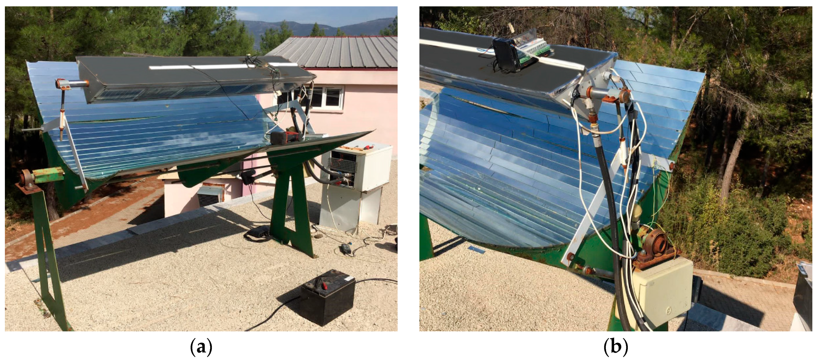
33]. In this study, the CPVT system was cooled with heat pumps (HP). A hybrid system (a CPVT system with HP) was manufactured and tested. A picture of the experimental setup is shown in
Figure 1. The technical specifications of the hybrid system are given in
Table 1. The CPVT collector consisted of a reflector, a triangular parabolic receiver, and a body. The CPVT hybrid system was created by placing the evaporator of the heat pump inside the triangle receiver of the CPVT collector (see
Figure 1).
A schematic diagram of the bifacial CPVT hybrid system (the CPVT system with HP) is given in
Figure 2. As seen in
Figure 2, the reflector concentrated the solar radiation into a triangular receiver. Mirrors were assembled on a parabolic body in the dimensions given in
Table 1 for a horizontal reflector with a length of 1.755 m. Each mirror was focused in the same way to ensure the homogeneous distribution of solar radiation on the triangular receiver’s surface. The CPVT system was positioned in an east–west direction along the trough and in the south–north direction in Muğla, Turkey (37°12′ N, 38°22′ E) at a fixed angle of 37° to the horizontal. Moreover, there was no protective glass cover on the reflector (as can be seen in
Figure 1 and
Figure 2). Thus, the solar radiation reaching the array of PV modules was increased despite the increase in the overall heat transfer coefficients and environmental thermal losses.
Figure 2 shows that the solar radiation was concentrated from the reflector to a 1.52 m long triangular receiver. A picture of the triangular receiver is demonstrated in
Figure 1. As shown in
Figure 1, the receiver extended in a triangular prismatic way in the focus line of the reflector. However, in order to receive solar radiation at sunrise and sunset, the height of the receiver was kept shorter than the height of the reflector. The two lower edges of the triangular trough (facing the reflector) were equipped with arrays of PV modules. The upper part of the receiver was used as a thermal absorber, as in conventional solar collectors (see
Figure 3). Therefore, the upper part received the solar radiation while the lower parts received the concentrated solar radiation. As can be seen in
Figure 1 and
Figure 3, six serially connected PV modules were added consecutively on the two lower sides. These partitions could be interconnected both in series and in parallel. Therefore, two arrays consisting of 12 PV modules each were obtained. The total surface area of the cells was 0.5674 m
2.
As seen in
Figure 3, the evaporator coils of the heat pump were placed in the empty space inside the triangular receiver. The heat in the trough was removed with a heat pump. Thus, the electrical efficiency of PV could be increased and the thermal energy demands for space heating could be met. The working fluid of the heat pump was R134a. The refrigerant pipes of the heat pump were inserted on the right side of the triangular trough (see
Figure 1).
Experimental tests were performed on the bifacial CPVT hybrid system. These tests were carried out on fully clear days during the winter heating season in Muğla, Turkey (37°12′ N 38°22′ E) as the climatic conditions. On a clear day, the CPVT system without a heat pump was tested, and the CPVT system with a heat pump was tested on a clear day. The tests started at 07:00 in the morning and continued collecting the data at the measurement sites at 15 min intervals until 19:00. Thus, the characteristics of the system at varying intensities of irradiance and varying operating temperatures were recorded, and the model was validated by making comparisons between the measurements and the outputs of the mathematical model.
As seen in
Figure 1 and
Figure 2, the lowest temperature of each PV module, the trough’s temperature, the reflector’s temperature, the ambient temperature, and the temperatures in the heat pump were measured with surface temperature sensors (T-type thermocouples, ±0.5 °C; PT100 sensors; ±0.2 °C), and the intensity of solar radiation and wind speed were measured with a pyranometer (EKO MS-602; 0–2000 W/m
2, 6.95 mV/W/m
2, ±10 W/m
2) and an anemometer (Wika; 0.2–10 m/s, ±0.2 m/s), respectively. The working flow rate in the heat pump was measured with an ultrasonic flowmeter (0.01–25 m/s, ±1%), and the pressures and the compressor’s power were measured with a manometer (0–10 bar, ±1%) and a wattmeter (0–6 kW, 50 Hz, ±1.5%), respectively. A wire-wound resistor was used for measurement of the electrical load of the PV.
3. Theoretical Analysis
The power output of all the PVs (in W) can be determined experimentally by using
where
and
denote, respectively, the short-circuit current in A and the open voltage in V.
The amount of solar radiation to the PV panels on the trough can be computed with
where
,
, and
denote the solar radiation in W/m
2, the surface area of the PVT system in m
2, and the optical efficiency of the concentrator, respectively.
is the concentration ratio in the bifacial CPVT system, as expressed below:
Under stable conditions, the exergy rate to the PV panels on the trough in W is given by
where
(which is equal to 6000 K) is the visible solar temperature. Conversely,
describes the exergy factor for thermal heating processes. The sun was assumed to be an infinite thermal source, and the exergy of the solar radiation absorbed by the system was computed with the Petela equation [
34] as follows:
More clearly, the exergy rate between the PV panels and the sun (in W) is
The amount of solar radiation between the absorber and the sun and its exergy rate in W can be determined, respectively, as
and
where
is the surface area of the absorber on the trough in m
2. In addition, the transmissivity (
) and absorption (
) give the effective transmission rate
. Once the coefficient of convective and radiative heat transfer between the external air and the absorber’s top surface has been computed, the total corresponding heat flow on the absorber in W can be computed as follows [
35]
where
,
, and
denote the temperature in K, the emittance, and the Stephane–Botzmann constant, respectively. The coefficient of convective heat transfer,
, in W/m
2·K, is computed using the following correlation, relating the Prandtl, Reynolds, and Nusselt numbers [
35]
where
is the air’s velocity in m/s.
The exergy rate between the absorber and ambient, in W, is given by
The concentrator’s area is much larger than that of the PVT receiver for the typical concentration ratio of the PVT system. Therefore, assuming that both the concentrator and the PVT system are gray surfaces, the sum of radiative and convective heat transfer between the concentrator and the PVT panels, in W, can be evaluated by using [
35,
36]
where
.
The exergy rate between the PVT panels and the concentrator, in W, is:
Under the assumptions of a steady flow and a steady state, the energy and exergy balances can be written as
where
,
,
,
h, and
s indicate the heat transfer rate in W, the work rate in W, the mass flow rate in kg/s, the enthalpy in kJ/kg, and the entropy in kJ/kgK, respectively. The subscripts 0 and
l express the reference (dead) state at
T0 and
P0 and the location, respectively.
is the specific flow exergy, in kJ/kg, expressed as
Finally, the total energy and exergy rates in the triangular trough (CPVT), in W, were calculated with the following equations, respectively,.
and
The mass, energy, and exergy balance equations for each piece of equipment in the air-to-air heat pump are as follows.
For the fan in the condenser:
In these expressions, , and denote the mass flow rate (in kg/s), the enthalpy (in kJ/kg), and the density (in kg/m3) of R134a and/or air, respectively. The is the efficiency of the fan and electrical motor, as a percentage.
The coolant flow rate (in kg/s) can be computed with Equation (28) in the computing procedure.
where
Vdisp,
ηV, and
n are the displacement volume of the compressor in m
3, the compressor’s volumetric efficiency as a percentage, and the rotation speed in rpm, respectively.
The energy and exergy balance equations for the HP-CPVT system are, respectively
The electrical, thermal, and total efficiencies for the CPVT can be defined as follows:
For the exergy analysis, they are
The electrical and thermal efficiencies for the HP-based CPVT system can be defined according to energy and exergy analyses, respectively, as follows:
The accuracy of the measurement devices was used to determine the uncertainty values in the experiments. Calculating the uncertainties of the measurements made during the tests is important for the reliability of the data. The uncertainty in experimental data can be determined by the method proposed by Kline and McClintock [
37], considering the experimentally obtained quantities, as stated below
where
R is a given function;
WR is the total uncertainty;
x1,
x2, ...,
xn are independent variables; and
w1,
w2, ...,
wn are the uncertainty in the independent variables. The total uncertainty values calculated and measured for the electrical and thermal efficiencies of the hybrid CPVT system were determined to be ±1.3% and ±2.3%, respectively. As a result, the values obtained for the parameters of all tests fully met the requirements of the theoretical and experimental methods.
4. Results and Discussion
In this study, a bifacial CPVT hybrid system with HP was manufactured and tests were carried out under real-world operation conditions. In bifacial CPVT systems with and without HP, the PV modules were cooled with heat pumps or were not cooled, respectively. To compare both systems, the time-dependent changes in solar radiation and the ambient air temperature are shown in
Figure 4. The experiments continued for one month (November 2020). Here, the data were taken on days when the solar radiation and air temperature values were very close to each other. It can be seen in
Figure 4 that the solar radiation and ambient air temperature in both systems changed equally. While the daily average solar radiation and ambient air temperature were 334 W/m
2 and 12.2 °C for the HP-CPVT system, they were 337 W/m
2 and 12.6 °C for the CPVT system. For both systems, the average maximum irradiance reached 578 W/m
2 and 581 W/m
2 in the CPVT systems with and without HP, respectively. As can be seen in
Figure 4, since the experiment was carried out under winter conditions, the solar radiation and ambient air temperature were low, and there were no significant temperature differences between the two systems. However, there were significant differences in electrical and thermal efficiencies.
The time-dependent changes in air velocity in the systems with and without HP are given in
Figure 5. The effects of convection on the CPVT system as well as those of radiation cannot be neglected. As seen in
Figure 5, the average air velocities of the experiments were close to each other, but the instantaneous air velocity had fluctuations. The average trough temperatures in the CPVT system were 15.62 °C and 17.10 °C, respectively, with and without HP. The daily average ambient air velocities for the CPVT and HP-CPVT systems were 0.96 m/s and 0.83 m/s, respectively.
The time-dependent change in the PV panels’ back surface temperature in the CPVT system is presented in
Figure 6a. The back surface temperatures of the PV panels ranged from 8.2 to 23.1 °C in the CPVT system. In
Figure 6a, a change similar to the daily change in solar radiation is observed. A similar observation is also seen in
Figure 6b for the change in the PV panels’ back surface temperatures for the HP-CPVT system. The temperatures ranged from 6.6 to 21.9 °C. Regarding
Figure 6a,b, the PV panels’ temperatures in the CPVT system were above the values of the HP-CPVT system. This situation may have been caused by the high ambient air velocity and the convection effect of the CPVT system in
Figure 5 compared with the other one.
As seen in
Figure 1 and
Figure 2, at the bottom of the triangular trough, the PV panels, starting with PV 1 in the first array up to PV 6, and starting with PV 7 in the second array up to PV 12, were arranged at the bottom of the triangular trough. The temperature distributions of the PV panels in the CPVT and HP-CPVT systems are depicted in
Figure 7. The temperature difference between each PV panel remained less than 1 °C. Moreover, the temperature of the PV modules in the first array was higher than that for the second array. This situation was thought to be caused by either the wind’s velocity or the problem of the focus of concentration. With the use of heat pumps in the CPVT system shown in
Figure 7, it was observed that the temperatures of each PV panel or duct fell steadily. In addition, while there was no significant temperature difference between the PV cells in the HP-CPVT system, there was an obvious temperature difference in the CPVT system.
The time-dependent changes in the production of electricity and electrical efficiency are presented in
Figure 8. The electrical efficiencies of the CPVT and HP-CPVT systems were calculated with Equations (31) and (33). In
Figure 8, the PV modules of the CPVT and HP-CPVT systems had a daily average instantaneous power of 19.83 W and 22.84 W, respectively. The electricity produced was 203.3 Wh in the CPVT system and 234.1 Wh in the HP-CPVT system during the day. Electricity generation was low because the average solar radiation and ambient temperature are about 335 W/m
2 and 12.4 °C, respectively, in November. Despite low radiation and a shorter sunshine duration in winter, electricity generation was increased by 15.2% with the cooling process (HP). As seen in
Figure 8, the daily average electrical efficiencies of the CPVT system with and without HP were 12.54% and 10.05%, respectively. Generally, the electrical efficiency of the HP-CPVT system was above that of the CPVT system. It was seen that the use of heat pumps during the hours when the amount of solar radiation was intense increased the electricity production of the PV modules. Thus, the tests of the designed HP-CPVT system have been verified.
The time-dependent changes in the rates of electrical production and consumption in the HP-CPVT system are given in
Figure 9. The total daily electricity production was 234.14 Wh, and the average daily instantaneous power between 08:30 and 18:30 was 22.84 W. The total daily electrical consumption by the fan and compressor were 180 Wh and 1322 Wh, respectively, while their average daily instantaneous power between 08:30 and 18:30 was 18 W and 129 W. There was an increase in the electricity consumed by the compressor between 11:30 and 15:30. The electricity consumed by the compressor increased because the PV modules became hotter at this time when the solar radiation was perpendicular to the ground. It was observed that the consumption of electricity was higher than the generation of electricity. However, as seen in
Figure 10, it was seen that the amount of heat dissipated in the condenser was greater than the electrical energy consumed.
Figure 10 shows the changes in the heating rate for some components of the hybrid HP-CPVT system. Here,
I and
Qconcen denote the radiation rate and the amount of heat transferred by radiation and convection that passed from the concentrator to the PV arrays, respectively. The heat (
QEVA) was withdrawn from the evaporator, which was placed on the back surface of the PV panels and discarded in the condenser. The change in the net thermal energy in the condenser (
QCON) was obtained by subtracting the electrical energy of the fan from the thermal energy in the condenser. If the energy absorbed by the refrigerant in the evaporator was subtracted from the total thermal energy in the triangular trough, the
QEVA value could be obtained. As seen in
Figure 10, the heat of the triangular trough (
Qtrough) and the evaporator (
QEVA) were almost the same and varied equally. The average daily instantaneous values were 224.4 W and 198.5 W for the triangular trough and the evaporator, respectively. It can be concluded that there was good heat transfer between the PV panels’ back surfaces and the evaporator. In addition, the condenser, (
QCON; average = 111.2 W) and the absorber (
Qabs) on the triangular trough (average 119.5 W) had approximate thermal values. Therefore, with the dimensions and technical characteristics of the system discussed in this study, it can be concluded that as much heat as the amount of heat falling on the absorber (
Qabs) can be discharged from the condenser (
QCON) to a heating medium. Thus, 1139.3 Wh of heat energy could be generated for heating purposes throughout the day.
The variation in the exergy destruction rate for each component of the HP-CPVT system with time is given in
Figure 11. As seen in
Figure 11, the highest amount of exergy destruction occurred in the CVPT system and then in the CPVT components of the HP-CPVT system. The average daily exergy destruction rates of the CPVT systems with HP (
Ėdes,HP-CPVT) and without HP (
Ėdes,CPVT for black dashed line) were 137.3 W and 163.96 W, respectively. The total daily exergy destruction rates of the CPVT systems with and without HP were 1407.3 Wh and 1680.6 Wh, respectively. It was observed that by using HP, the exergy destruction rate in the CPVT system could be reduced. This resulted in better cooling in the PV panels and more thermal energy removed from the triangular trough. However, this was the component with the highest exergy destruction in the hybrid system. Improvements in this component are seen as a priority from a design point of view in the HP-CPVT system. Regarding
Figure 11, the total daily exergy destruction rates for the evaporator (
Ėdes,EVA), the compressor (
Ėdes,COMP), and the condenser (
Ėdes,CON) of the HP-CPVT system were calculated as 342.5 Wh, 427 Wh, and 851.9 Wh, respectively. The average daily exergy destruction rates for the evaporator (
Ėdes,EVA), the compressor (
Ėdes,COMP), and the condenser (
Ėdes,CON) of the HP-CPVT system were calculated as 33.42 W, 42 W and 83.1 W, respectively. The exergy destruction rate of the condenser is not expected to be higher than that of the compressor. However, in the exergy analysis, the useful (produced) exergy of the condenser was within the exergy destruction rate, as can be seen in
Figure 11.
The changes in the electrical and thermal efficiencies of the bifacial CPVT system with and without HP according to an energy analysis are presented in
Figure 12a. The electrical and thermal efficiencies of CPVT with and without HP were calculated with Equations (31) and (32). According to
Figure 12a, the average electrical efficiency of the CPVT system for Equation (31) was approximately 10.05% during the day. The average electrical efficiency of the HP-CPVT increased to 12.54% with the cooling of the PV modules. The thermal efficiency of the HP-CPVT hybrid system depended on the heat load in the condenser and evaporator. The electricity produced by the cooling of the HP-CPVT system increased. The average thermal efficiency decreased from 81.97% to 38.37%. As a result, 234.14 Wh of electricity was produced from 12 PV panels on the two surfaces (i.e., two strings) of the 152 cm triangular trough in the HP-CPVT system. In contrast, 1502 Wh of energy was consumed by the fan and compressor (see
Figure 9). For the system considered in this study, if the length of the triangular groove can be increased by approximately six times at the same energy consumption, it can be operated with its own electricity. On the other hand, 1139.3 Wh of heat can be obtained from the condenser (see
Figure 10). This value will increase even more.
Figure 12b depicts the changes in the electrical and thermal energy efficiencies of the bifacial CPVT system with and without HP based on the exergy analysis. The electrical and thermal exergy efficiencies of the CPVT system with and without HP were calculated with Equations (34) and (35). The electrical exergy efficiencies of the CPVT system with and without HP were approximately 14.65% and 10.73%, respectively, as shown in
Figure 12b. The thermal exergy efficiencies of the CPVT system with and without HP were 82.47% and 85.63%, respectively. The electrical exergy efficiency increased by 36.5% and the thermal exergy efficiency decreased by 3.7%.
The electrical and thermal energy efficiencies of the CPVT system with HP, according to the energy and exergy analyses, were calculated with Equations (37)–(40), and the results are given in
Figure 13. As can be seen in
Figure 13, the electrical and thermal energy efficiencies of the HP-CPVT system were 6.48% and 31.23%, respectively. The electrical and thermal exergy efficiencies of the HP-CPVT system were 6.72% and 26.13%, respectively.
The electrical and thermal energy efficiencies of the HP-CPVT system were calculated in two ways, with and without considering the electricity consumed by the compressor and fan. It was assumed that the electricity consumed by the compressor and fan were provided by the solar power plant, so it was neglected in Equations (31)–(36). However, it was taken account in Equations (37)–(40), so the electrical and thermal energy efficiencies of the HP-CPVT system decreased by 48.3% and 18.6%, respectively, and the electrical and thermal exergy efficiencies of the HP-CPVT system decreased by 82.5% and 68.3%, respectively.


