
Per-Phase Power Controller for Smooth Islanded Transitions in Three-Phase Three-Wire Systems


Abstract
:1. Introduction
2. Basics of Power Control
2.1. Three-Phase Four-Wire (3-4w) Networks
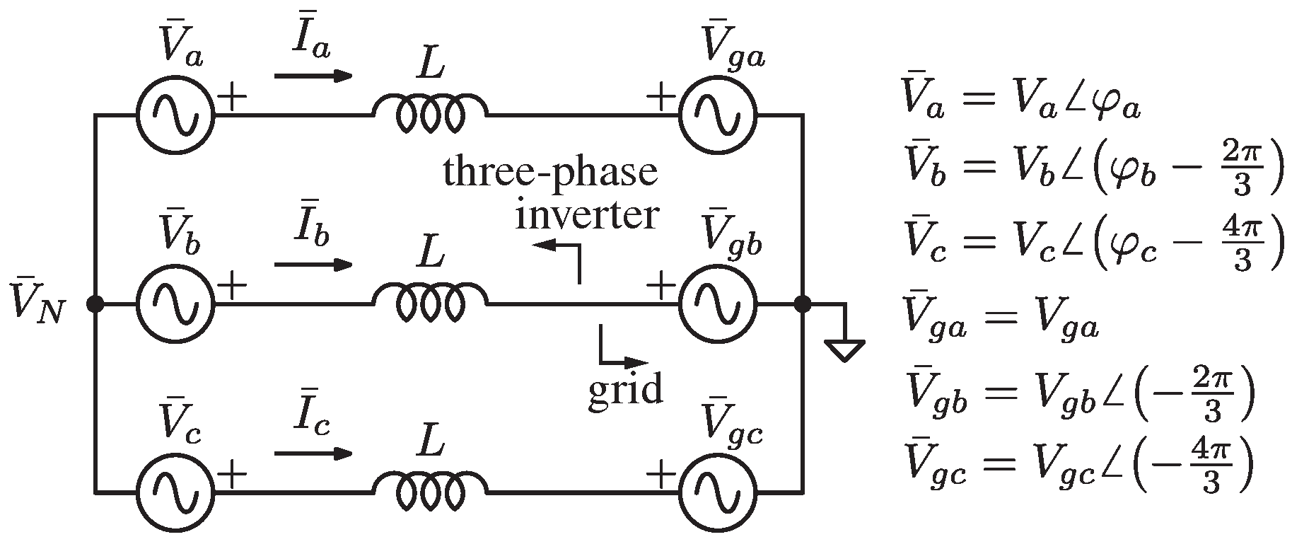
2.2. Three-Phase Three-Wire (3-3w) Networks
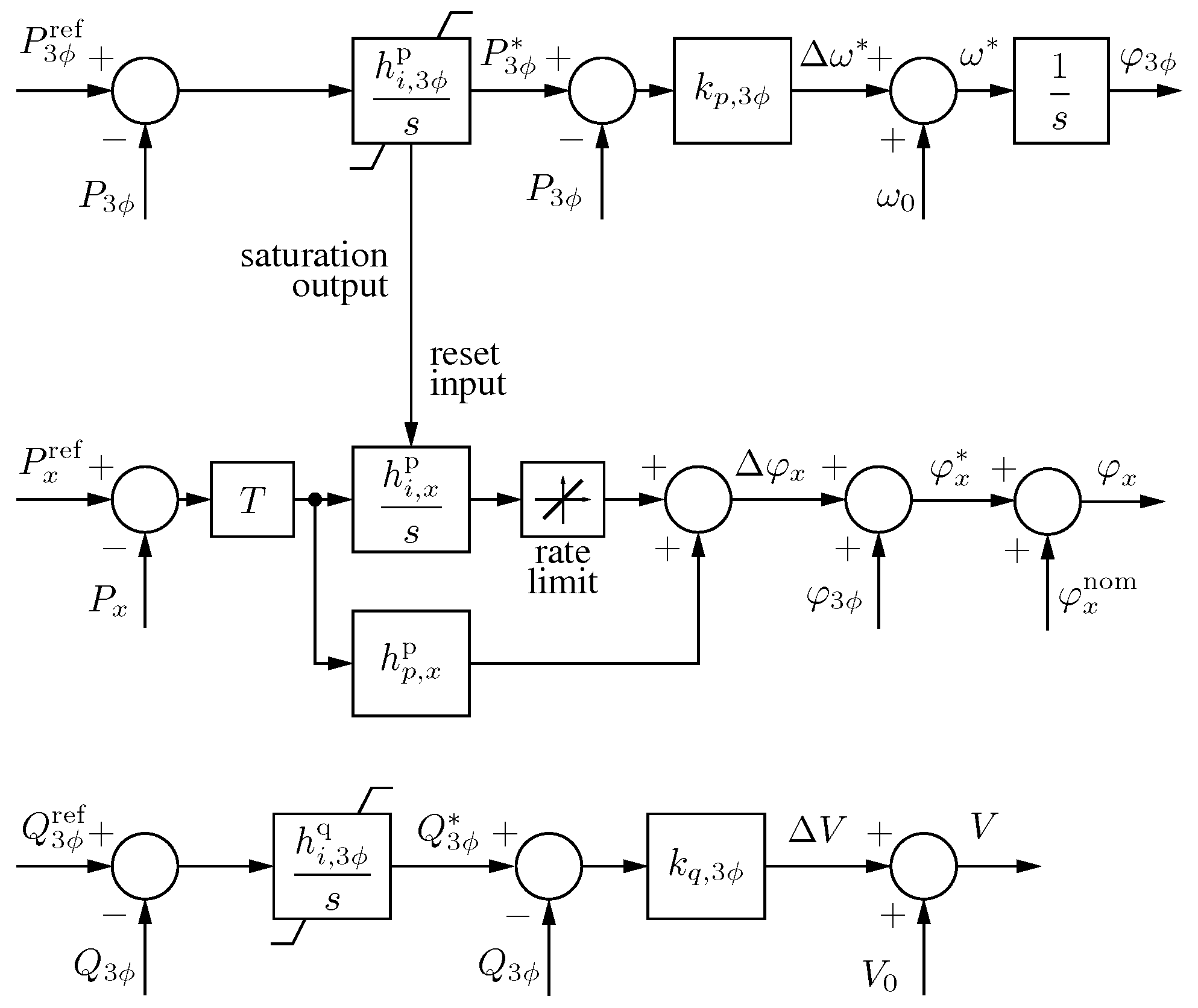
3. Per-Phase Power Control in Three-Phase Three-Wire Systems
3.1. Grid-Connected Operation
3.2. Islanded Operation
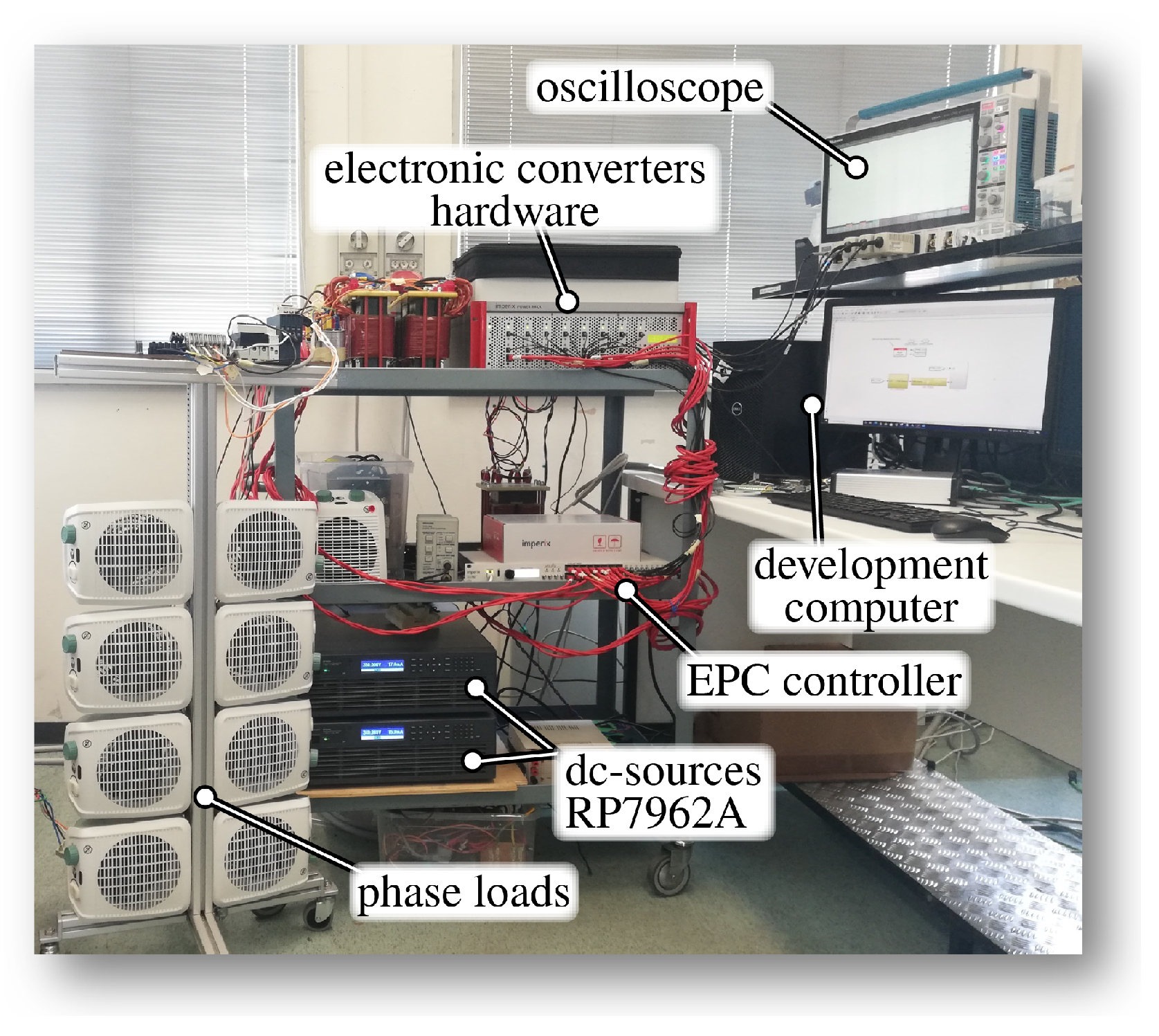
4. Validation Results
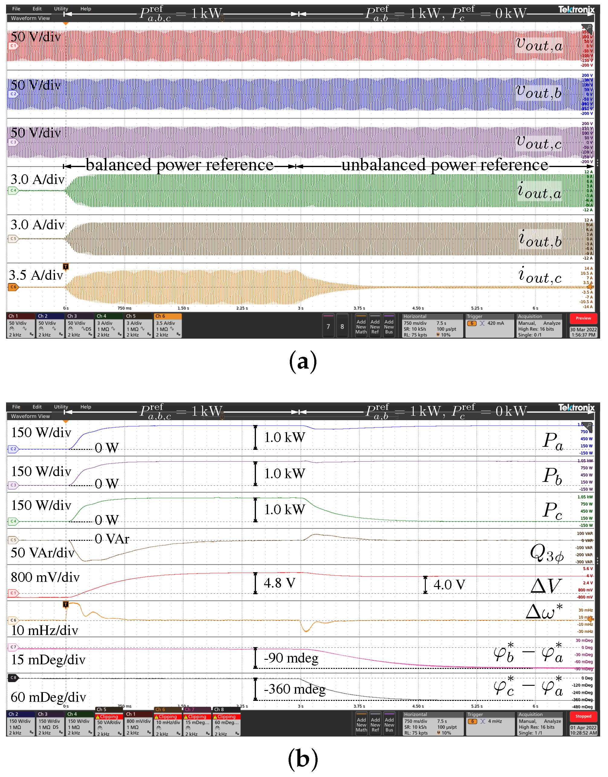
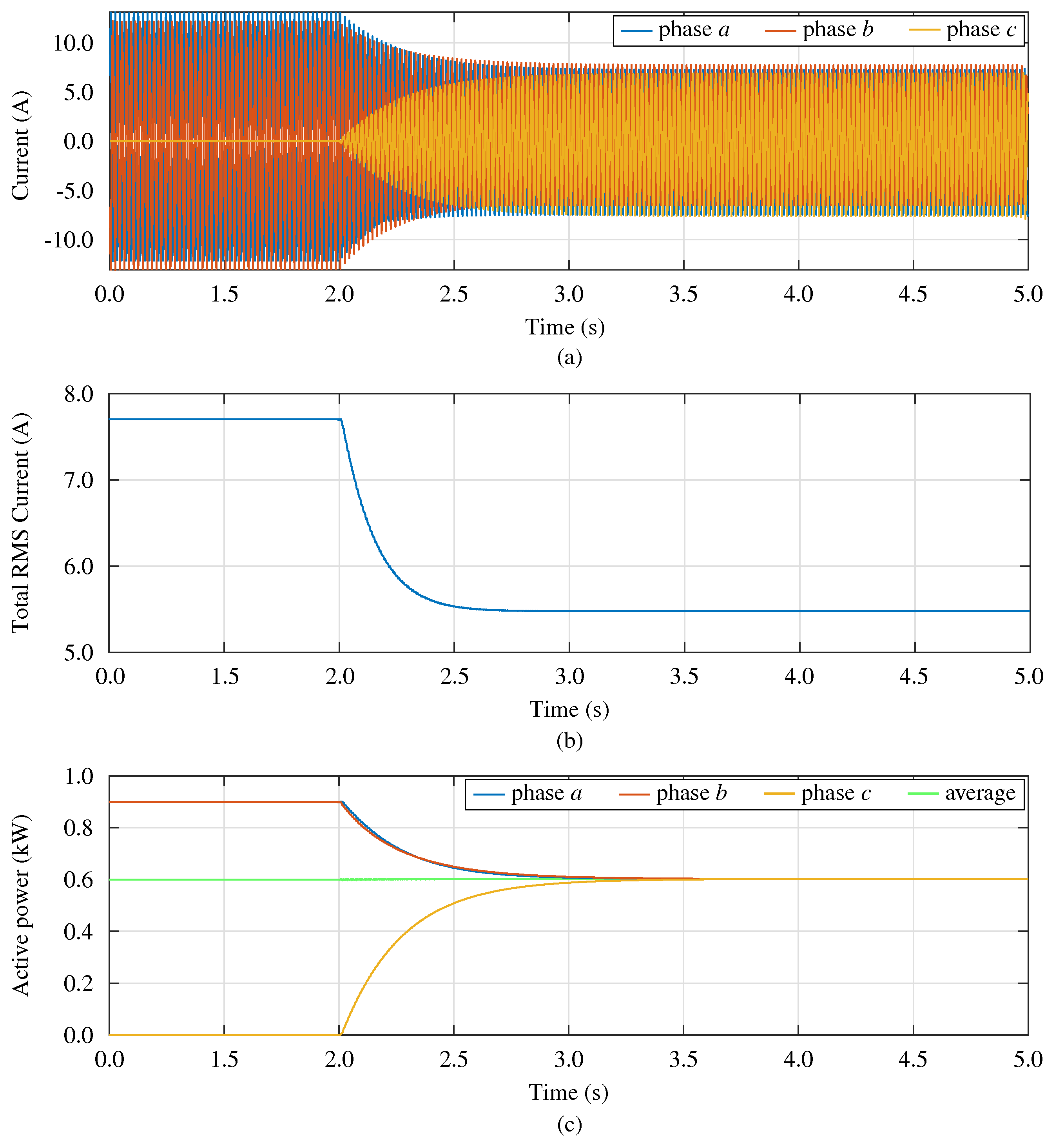
4.1. Balanced and Unbalanced Power Reference Variations
4.2. Transition of Grid-Tied to Islanded Operation
4.3. Example of Application
5. Conclusions
Author Contributions
Funding
Informed Consent Statement
Data Availability Statement
Conflicts of Interest
References
- Xu, S.; Xue, Y.; Chang, L. Review of Power System Support Functions for Inverter-Based Distributed Energy Resources- Standards, Control Algorithms, and Trends. IEEE Open J. Power Electron. 2021, 2, 88–105. [Google Scholar] [CrossRef]
- Alazemi, T.; Darwish, M.; Radi, M. TSO/DSO Coordination for RES Integration: A Systematic Literature Review. Energies 2022, 15, 7312. [Google Scholar] [CrossRef]
- Simmini, F.; Agostini, M.; Coppo, M.; Caldognetto, T.; Cervi, A.; Lain, F.; Carli, R.; Turri, R.; Tenti, P. Leveraging Demand Flexibility by Exploiting Prosumer Response to Price Signals in Microgrids. Energies 2020, 13, 3078. [Google Scholar] [CrossRef]
- Abedini, H.; Caldognetto, T.; Mattavelli, P.; Tenti, P. Real-Time Validation of Power Flow Control Method for Enhanced Operation of Microgrids. Energies 2020, 13, 5959. [Google Scholar] [CrossRef]
- Hamidieh, M.; Ghassemi, M. Microgrids and Resilience: A Review. IEEE Access 2022, 10, 106059–106080. [Google Scholar] [CrossRef]
- Caldognetto, T.; Abedini, H.; Mattavelli, P. A Per-Phase Power Controller for Smooth Transitions to Islanded Operation. IEEE Open J. Power Electron. 2021, 2, 636–646. [Google Scholar] [CrossRef]
- Espina, E.; Espinoza, M.; Cárdenas, R. Active power angle droop control per phase for unbalanced 4-wire microgrids. In Proceedings of the 2017 IEEE Southern Power Electronics Conference (SPEC), Puerto Varas, Chile, 4–7 December 2017; pp. 1–6. [Google Scholar] [CrossRef]
- Liu, B.; Liu, Z.; Liu, J.; An, R.; Zheng, H.; Shi, Y. An Adaptive Virtual Impedance Control Scheme Based on Small-AC-Signal Injection for Unbalanced and Harmonic Power Sharing in Islanded Microgrids. IEEE Trans. Power Electron. 2019, 34, 12333–12355. [Google Scholar] [CrossRef]
- Fazeli, S.M.; Ping, H.W.; Rahim, N.B.A.; Ooi, B.T. Individual-phase control of 3-phase 4-wire voltage–source converter. IET Power Electron. 2014, 7, 2354–2364. [Google Scholar] [CrossRef]
- Hsu, H.C.; Chung, N.T.; Chen, Y.M.; Hsu, C.C. Grid Voltage Balancing Strategy Based on Per-Phase-Controlled Inverters. In Proceedings of the 2021 IEEE International Future Energy Electronics Conference (IFEEC), Taipei, Taiwan, 16–19 November 2021; pp. 1–6. [Google Scholar] [CrossRef]
- CIGRE Task Force C6.04.02. Benchmark Systems for Network Integration of Renewable and Distributed Energy Resources; Technical Report; International Council on Large Electric Systems: Paris, France, 2014. [Google Scholar]
- Das, H.S.; Nurunnabi, M.; Salem, M.; Li, S.; Rahman, M.M. Utilization of Electric Vehicle Grid Integration System for Power Grid Ancillary Services. Energies 2022, 15, 8623. [Google Scholar] [CrossRef]
- Sufyan, A.; Jamil, M.; Ghafoor, S.; Awais, Q.; Ahmad, H.A.; Khan, A.A.; Abouobaida, H. A Robust Nonlinear Sliding Mode Controller for a Three-Phase Grid-Connected Inverter with an LCL Filter. Energies 2022, 15, 9428. [Google Scholar] [CrossRef]
- Madadi, M.; Zou, K.; Bhattacharya, S. Unified Control Method for Seamless Transition of a Weak Grid Connected AC Microgrid to Islanded Mode. In Proceedings of the 2022 IEEE Energy Conversion Congress and Exposition (ECCE), Detroit, MI, USA, 9–13 October 2022; pp. 1–8. [Google Scholar] [CrossRef]
- Timbus, A.; Liserre, M.; Teodorescu, R.; Rodriguez, P.; Blaabjerg, F. Evaluation of Current Controllers for Distributed Power Generation Systems. IEEE Trans. Power Electron. 2009, 24, 654–664. [Google Scholar] [CrossRef]
- Guerrero, J.M.; Vasquez, J.C.; Matas, J.; de Vicuna, L.G.; Castilla, M. Hierarchical Control of Droop-Controlled AC and DC Microgrids—A General Approach Toward Standardization. IEEE Trans. Ind. Electron. 2011, 58, 158–172. [Google Scholar] [CrossRef]
- Lissandron, S.; Mattavelli, P. A controller for the smooth transition from grid-connected to autonomous operation mode. In Proceedings of the 2014 IEEE Energy Conversion Congress & Exposition (ECCE), Pittsburgh, PA, USA, 14–18 September 2014; pp. 4298–4305. [Google Scholar] [CrossRef]
- Ivanov, O.; Neagu, B.C.; Niţu, A.I.; Gavrilaş, M. An Improved Metaheuristic Algorithm for Load Balancing in LV Distribution Networks. In Proceedings of the 2021 9th International Conference on Modern Power Systems (MPS), Cluj-Napoca, Romania, 16–17 June 2021; pp. 1–5. [Google Scholar] [CrossRef]
- Ivanov, O.; Neagu, B.C.; Cibotărică, A.; Gavrilaş, M. Multiobjective Prosumer Surplus Management for Optimal Microgrid Operation. In Proceedings of the 2021 10th International Conference on Energy & Environment (CIEM), Bucharest, Romania, 14–15 October 2021; pp. 1–5. [Google Scholar] [CrossRef]
- Hadjidemetriou, L.; Charalambous, A.; Kyriakides, E. Control Scheme for Phase Balancing of Low-Voltage Distribution Grids. In Proceedings of the 2019 International Conf. Smart Energy Systems and Technologies (SEST), Porto, Portugal, 9–11 September 2019; pp. 1–6. [Google Scholar] [CrossRef]
- Guan, S.; Tao, S.; Song, Y. Application research of IEEE Std.1459–20 10 in three-phase three-wire system. In Proceedings of the 2022 IEEE 6th Information Technology and Mechatronics Engineering Conference (ITOEC), Chongqing, China, 4–6 March 2022; Volume 6, pp. 511–515. [Google Scholar] [CrossRef]
- Brandao, D.I.; Araujo, L.S.; Alonso, A.M.S.; dos Reis, G.L.; Liberado, E.V.; Marafão, F.P. Coordinated Control of Distributed Three- and Single-Phase Inverters Connected to Three-Phase Three-Wire Microgrids. IEEE Trans. Emerg. Sel. Topics Power Electron. 2020, 8, 3861–3877. [Google Scholar] [CrossRef] [Green Version]
- Burgos-Mellado, C.; Llanos, J.; Espina, E.; Sáez, D.; Cárdenas, R.; Sumner, M.; Watson, A. Single-Phase Consensus-Based Control for Regulating Voltage and Sharing Unbalanced Currents in 3-Wire Isolated AC Microgrids. IEEE Access 2020, 8, 164882–164898. [Google Scholar] [CrossRef]
- Brandao, D.I.; Caldognetto, T.; Marafão, F.P.; Simões, M.G.; Pomilio, J.A.; Tenti, P. Centralized Control of Distributed Single-Phase Inverters Arbitrarily Connected to Three-Phase Four-Wire Microgrids. IEEE Trans. Smart Grid 2017, 8, 437–446. [Google Scholar] [CrossRef] [Green Version]
- Tenti, P.; Caldognetto, T. Generalized Control of the Power Flow in Local Area Energy Networks. Energies 2022, 15, 1416. [Google Scholar] [CrossRef]
- IEEE Std 2030.7-2017; IEEE Standard for the Specification of Microgrid Controllers. IEEE: Piscataway, NJ, USA, 2018. [CrossRef]
- De Brabandere, K.; Bolsens, B.; Van den Keybus, J.; Woyte, A.; Driesen, J.; Belmans, R. A Voltage and Frequency Droop Control Method for Parallel Inverters. IEEE Trans. Power Electron. 2007, 22, 1107–1115. [Google Scholar] [CrossRef]
- Yao, W.; Chen, M.; Matas, J.; Guerrero, J.M.; Qian, Z. Design and Analysis of the Droop Control Method for Parallel Inverters Considering the Impact of the Complex Impedance on the Power Sharing. IEEE Trans. Ind. Electron. 2011, 58, 576–588. [Google Scholar] [CrossRef]
- Zhong, Q.; Boroyevich, D. Structural Resemblance Between Droop Controllers and Phase-Locked Loops. IEEE Access 2016, 4, 5733–5741. [Google Scholar] [CrossRef]
- Delghavi, M.B.; Yazdani, A. A Unified Control Strategy for Electronically Interfaced Distributed Energy Resources. IEEE Trans. Power Del. 2012, 27, 803–812. [Google Scholar] [CrossRef]


| Control Kind | Islanded Operation | Grid-Tied/Island. Trans. | Three-Phase Power Tracking | Power Tracking | 3-4w & 3-3w Operation |
|---|---|---|---|---|---|
| Grid feeding | - | - | + | + | + |
| Traditional droop | + | + | - | - | + |
| Droop with 3 P&Q track | + | + | + | - | + |
| Per-phase control in [6] | + | + | + | + | - |
| Technique proposed herein | + | + | + | + | + |
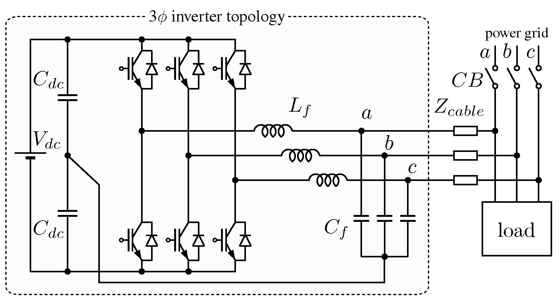
| Parameter | Symbol | Value |
|---|---|---|
| EPCs parameters | ||
| DC-link voltage | 350 | |
| DC-link capacitor | ||
| DC-link inductor | ||
| Output filter capacitor | 50 | |
| Output filter inductor | ||
| Switching frequency | 20 | |
| Nominal power rating | 3 | |
| Nominal grid voltage rms | 110 | |
| Nominal grid frequency | ||
| Main grid frequency range | ||
| control parameters | ||
| P–f droop coefficient | ||
| V–Q droop coefficient | ||
| 3-phase P contr. integ. gain | ||
| 3-phase P saturation limit | ||
| Per-phase P contr. integ. gain | ||
| Per-phase P contr. prop. gain | ||
| 3-phase Q contr. integ. gain | ||
| Per-phase Q saturation limit | ||
| Nominal voltage amplitude | ||
| Nominal frequency | ||
| Maximum frequency variation | % | |
| Maximum voltage variation | 10 % | |
Disclaimer/Publisher’s Note: The statements, opinions and data contained in all publications are solely those of the individual author(s) and contributor(s) and not of MDPI and/or the editor(s). MDPI and/or the editor(s) disclaim responsibility for any injury to people or property resulting from any ideas, methods, instructions or products referred to in the content. |
© 2023 by the authors. Licensee MDPI, Basel, Switzerland. This article is an open access article distributed under the terms and conditions of the Creative Commons Attribution (CC BY) license (https://creativecommons.org/licenses/by/4.0/).
Share and Cite
Lauri, A.; Caldognetto, T.; Biadene, D.; Abedini, H.; Mattavelli, P. Per-Phase Power Controller for Smooth Islanded Transitions in Three-Phase Three-Wire Systems. Energies 2023, 16, 672. https://doi.org/10.3390/en16020672
Lauri A, Caldognetto T, Biadene D, Abedini H, Mattavelli P. Per-Phase Power Controller for Smooth Islanded Transitions in Three-Phase Three-Wire Systems. Energies. 2023; 16(2):672. https://doi.org/10.3390/en16020672
Chicago/Turabian StyleLauri, Andrea, Tommaso Caldognetto, Davide Biadene, Hossein Abedini, and Paolo Mattavelli. 2023. "Per-Phase Power Controller for Smooth Islanded Transitions in Three-Phase Three-Wire Systems" Energies 16, no. 2: 672. https://doi.org/10.3390/en16020672