Article

A Novel Three-Layer Symmetry Winding Configuration for Five-Phase Motor

Department of Electrical and Information Engineering, Jiangsu University, Zhenjiang 212013, China
*
Author to whom correspondence should be addressed.
Energies 2023, 16(2), 682; https://doi.org/10.3390/en16020682
Submission received: 5 November 2022 / Revised: 19 December 2022 / Accepted: 1 January 2023 / Published: 6 January 2023
(This article belongs to the Section F: Electrical Engineering)

Abstract

:
This paper presents a new three-layer, five-phase winding configuration theory of unconventional slot-pole combinations by each layer of winding for a phase vector correction, three layers of winding superimposed together to achieve the results of three-phase symmetry. Since the single-layer unconventional winding has to have an empty slot to meet its symmetry, based on the characteristics of single-layer winding, the unconventional winding design is carried out. Based on the simulation comparison between the single-layer unconventional winding and double-layer unconventional winding, a three-layer, nine-phase unconventional winding is proposed, which is based on the theory of single-layer unconventional winding, and three layers are staggered and stacked to realize nine-phase winding, which not only increases the utilization rate of the winding slot but also improves the fault tolerance performance. In addition, a 105-slot, 20-pole, three-layer, five-phase motor is proposed for a winding configuration and performance analysis to achieve both low torque pulsation and high fault tolerance.

1. Introduction

With the advantages of high efficiency, high power density and high torque density, permanent magnet motors have promising applications in the aerospace, defense and military industries [1,2]. With the increasingly demanding requirements for safety and reliability in these applications, strongly fault-tolerant permanent magnet motors have become a major need [3,4]. In order to meet the need for fault-tolerant operation under faults, the motor design needs to ensure good electromagnetic isolation between the different phase windings; therefore, the winding structure is often a single-layer centralized winding. In order to make the single-layer winding also have the characteristics of low torque pulsation and to make the three-phase winding meet the high vector symmetry, this paper improves the number of non-conventional slots based on the slot potential star diagram method and designs the single-layer non-conventional winding. With the increasing power level and reliability requirements of motor speed-control systems in some application fields, the limitations of traditional three-phase motors are gradually highlighted, and multi-phase motors become an important way to effectively solve this problem. The high-speed development of power electronics technology and modern control theory makes power electronic converters widely used in AC drive systems; the number of motor phases is no longer limited by the number of phases of the grid supply.
The slot potential star diagram is a traditionally used winding configuration method [5,6,7]. Drawing a slot potential star diagram means that the sinusoidal electric potential of each conductor embedded in the stator slot is represented by a vector separately, and the vectors in the same direction are superimposed together to form a star-shaped radial vector diagram. Currently, AC conventional windings have a relatively well-developed theory [8], and integer slot windings have been very widely used in permanent magnet-assisted synchronous reluctance motors [9,10]. Although the configuration of integer slot winding is very convenient, the winding produces large torque pulsation; therefore, many scholars proposed fractional slot winding, which brings both challenges and opportunities [11]. Compared with the integer slot, the fractional slot winding has the advantages of lower winding losses and lower torque pulsation, and some issues have been proposed for the fractional slot winding [12]; some scholars specifically discussed the effect of winding form on the permanent magnet-assisted synchronous reluctance motor [13]. The demagnetization field of a concentrated winding motor is more concentrated, while the demagnetization field of a distributed winding motor is more dispersed. Among the existing fractional slot winding design theories, some scholars have proposed a double-layer winding that requires an odd number of phases and a fixed pitch of all coils, or a single-layer winding that requires an odd number of phases and a fixed odd pitch of all coils [14,15]. Obviously, its applicability is very limited, so there is a great deficiency in the generality of the method. Starting from the pitch, there exists winding configuration schemes for two pitches of 2 and 3, respectively [16,17], and the winding coil pitch is not exactly equal, which will have a certain effect on the torque [18]. For unconventional single-layer windings, the application to unconventional slot-pole fits is very different from the phase-splitting method used for double-layer windings, which requires the calculation of the slot potential vector for each winding based on the slot potential star diagram to find the optimal solution and then phase-splitting. An unbalanced winding has been designed, and the applicability of the slot-pole coordination of the winding has been investigated [19]. Currently, the applicability of this scheme is only for motors with integer multiples of the number of slots in the phase, and its torque pulsation is effectively reduced in terms of performance. Other scholars have also studied unconventional winding motors with 39 slots specifically [20,21], but there is no generalized theory that can be used for arbitrary slot-pole fits. In addition, no winding balance structure has been proposed for multi-phase motors.
In this paper, a 39-slot, 6-pole motor is used as an example to achieve approximate symmetry of the three-phase windings by redundant sets of vectors with specific slot offsets to achieve low-torque ripple based on a slot potential star diagram [22]. However, a common problem with this approach for single-layer windings is the presence of empty slots, which results in low slot utilization, and the non-conventional windings are connected in a different way than conventional single-layer chain, crossover and concentric connections due to their variable pitch. The slot utilization problem can be solved by multi-layer stacking, which can be stacked into three layers of windings. Therefore, a three-layer, five-phase winding is proposed, in which each layer is corrected for a phase vector, and the three layers are stacked together to achieve a three-phase symmetric result. Finally, the winding configuration and performance analysis of a 105-slot, 20-pole, five-phase motor are performed to achieve both low-torque pulsation and high fault tolerance performance. The contribution of this paper is to achieve simultaneous winding balance and high slot space utilization using multi-layer stacking of single windings and to propose a multiphase motor structure with balanced windings.

2. Single-Layer Unconventional Winding Configuration Scheme

2.1. Principle of Phase Separation

The slot phase separation principle of single-layer unconventional winding is based on the slot potential star diagram, and the approximate symmetry of three-phase winding is realized by the redundancy of a group of vectors and a specific slot offset. Such a winding configuration scheme needs to know the number of stator slots and rotor poles of the motor, and then calculates the number of offset slots from the vector. Take a 39-slot, 6-pole motor, as an example, and draw its slot potential star diagram first. First, take four vectors to make the three-phase vector difference as 120° as far as possible, as shown in Figure 1a.
Take the number corresponding to the remaining vector as the slot number for phase adjustment. Since the adjacent vectors of the adjustment vector are phase B and phase C, the appropriate amount of phase A will not be adjusted. Take the vectors on the far side of the adjacent phase belt of phase B and phase C, respectively, to offset the slot. Assume that these two vectors are EB4 and EC4, respectively, and the remaining vectors are EB1, EB2, and EB3, and EC1, EC2 and EC3, respectively. Assuming that the offset vector is Es5, if the vector offset of BC two phases is set to X and Y, respectively, the phase difference relationship between the vector sums of each phase is required to meet EA1 + EA2 + EA3 + EA4, EB1 + EB2 + EB3 + (1 − x)EB4 + xES5 and EC1 + EC2 + EC3 + (1 − y)EC4 + yES5. The phase difference of this three-phase vector is approximately 120°, and it must be a full slot offset. By symmetry, the equilibrium between the two phases can be achieved when each phase B, C occupies one third of the offset vector; therefore, the final solution is x = y = 0.3333, that is, BC two phases are offset by one slot, and the final result is shown in Figure 1b. The results of the distribution to phases are given in Table 1.

2.2. Winding Connection Scheme

The winding connection of a 39-slot, 6-pole motor is shown in Figure 2. It can be seen that the winding connection is much simpler than that of the double-layer winding. The pitch of this kind of unconventional winding is no longer fixed due to the slot offset, and its three-phase vector difference is very close to 120°, which is greatly improved compared with the double-layer unconventional winding.
In order to compare the performance, it is compared with the double-layer unconventional unbalanced winding of 39-slot, 6-pole winding. The winding connection diagram is shown in Figure 3. Its symmetry is higher than that of the double-layer unconventional winding.
The torque simulation of the two windings under the same stator and embedded PM rotor structure model of the PM-assisted synchronous reluctance motor verifies the excellent torque performance of the 39-slot, 6-pole motor compared with the single-layer motor under the unbalanced winding method. With the same parameters, except for the winding connection method, the torque waveform is shown in Figure 4. The average torque and torque ripple of the unbalanced winding connection method and the single-layer unconventional winding method are 15.1 Nm, 9.57% and 12.7 Nm, 11.83%, respectively. It can be seen that the performance of the winding connection mode under the proposed unbalanced winding method is better.

3. Three-Layer Unconventional Winding Configuration Promotion

3.1. Three-Layer, Nine-Phase Unconventional Winding

For the 39-slot, 6-pole, single-phase unconventional winding, after the three-phase windings are configured, there are three slots without embedded windings, which reduces the torque performance of the motor and has certain defects. Therefore, on this basis, it is proposed to configure three-phase windings with the configuration theory of single-layer winding, so that the three-phase windings are different from each other by a certain angle, forming an approximately symmetrical nine-phase winding, that is, the torque performance of the motor is improved, and the fault-tolerant performance is enhanced.
Taking a 105-slot, 20-pole motor as an example, this paper analyzes it in detail. First, the phase separation is carried out without considering the slot offset. One vector is redundant. If the slot offset is not carried out, the three-phase vector angles are −20.77°, −131.53° and 103.84°, respectively, which does not meet the three-phase symmetry. The solution is the same as that of single-layer unconventional winding. The three-phase symmetry is best met through slot offset.
However, for the convenience of discussion, phase A is taken as the fixed phase, and only the BC two-phase slots are offset. Similarly, set the offset of BC two phase as X and Y, respectively, and each phase vector is superimposed. Calculate X and Y according to the desired angle so as to offset the corresponding number of slots.
Because phase A is taken as the stationary phase, its vector does not need to be changed. The vector diagram is shown in Figure 5, and the final synthetic vector angle is −20.77°.
The angle analysis diagram of the phase B vector is shown in Figure 6. Turn the negative direction vectors EB1 and Eb2 by 180° to get Eb1* and Eb2*, and each vector contains nine slot components. When there is no groove offset, that is when x = 0, the synthetic vector angle of phase B is −131.53°, while the actual angle to be taken is −20.77° − 120° = −140.77°. It can be seen that it should be offset to the ES side. Therefore, Eb4 can be replaced by the slot corresponding to Es so as to realize the angle adjustment, so that it is 120° different from phase A. Finally, the vector diagram of phase B is shown in Figure 7, so that the sum angle of its vectors is equal to −140.77°. Because the angle is between EB3 vector and Eb1*, the obtained x must be greater than 1 − x.
In order to solve X by angle, the superposition calculation of each vector is shown in Figure 8. The final synthetic amount is EB, and the initial length of each amount is 1. After the slot offset, the final length of ES and Eb4 are x and 1 − x, respectively. For the convenience of the calculation, a vector with a length of 2x − 1 is introduced, and the triangle formed with EB and Eb* can be obtained by the sine theorem of formula (1), where a, b and c is (2x − 1) *Eb4, EB and Eb*, respectively. X = 0.67 corresponds to 9 slots on each vector. Therefore, the 6 slots on eb4 are replaced by the slots on Es.
a sin A = b sin B = c sin C
The angle analysis diagram of the phase C vector is shown in Figure 9. Turn the negative direction vectors EC3 and EC4 by 180° to obtain EC3* and Ec4*, and each vector contains nine slot components. When there is no slot offset, that is when y = 0, the synthetic vector angle of phase C is 103.84°, while the actual angle to be taken is −20.77° + 120° = 99.23°. It can be seen from the figure that it should be offset to the eb4 reverse vector Eb4* side. Therefore, the remaining slots after the EB4 slot offset can be used to replace EC4 so as to realize the angle adjustment, making it 120° different from phase A. Finally, the vector diagram of phase C is shown in Figure 10, making the sum of its vectors equal to 99.23°.
In order to solve y by angle, the superposition calculation of each vector is shown in Figure 11. The final synthetic appropriate amount is EC, and the initial length of each appropriate amount is 1. After the slot offset, the final length of eb4 and EC4 are y and 1 − y, respectively. For the convenience of the calculation, a vector with a length of 1 − 2y is introduced, and the triangle formed with EC and Ec* can be obtained by the sine theorem of formula (1). Y = 0.33 corresponds to 9 slots on each vector. Therefore, the three slots on EC4 are replaced by the slots on Eb4.
The above is the phase separation result of the first-layer winding. In order to avoid empty slots and improve fault tolerance, the second and third layers rotate the phase vectors of the phase separation result by 27.69°, that is to stagger one vector in turn, and then form a nine-phase winding. The final vector diagram is shown in Figure 12.

3.2. Three-Layer, Five-Phase Unconventional Winding

The composition principle of three-layer, five-phase unconventional winding is different from that of the above nine phases. Each layer of winding adjusts the phase of one of the five phases, and three layers are superimposed to achieve the effect of symmetry. This configuration scheme will no longer use the method of slot offset, directly select the vector, and realize phase adjustment through multi-layer winding, which also ensures that there is no empty slot. Take the 105-slot, 20-pole, five-phase motor for detailed analysis. The three-layer winding slot potential star diagram and phase separation results are shown in Figure 13. The first-layer winding is shown in Figure 13a to adjust the phase of b+. The second-layer winding is shown in Figure 13b to adjust the phase of e+. The third-layer winding group is shown in Figure 13c to adjust the phase of c+. After the synthesis calculation of three groups of vectors, symmetry can be achieved after the superposition of three layers.

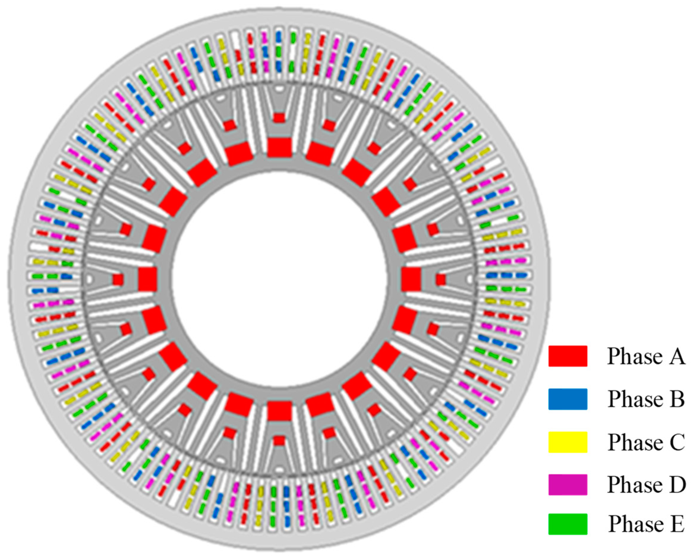
4. 105-Slot, 20-Pole, Triple-Winding, Five-Phase Motor

In order to study the influence of unconventional winding on machine performance, a triple-winding, 105-slot, 20-pole machine’s schematics are shown in Figure 14. The PM material is Y30, and the remanent magnetization is 0.4T. Similar to the slot and pole structure, the motor uses the previous three-layer winding structure instead of the traditional double-layer winding structure, which provided higher winding utilization and hence improved motor output performance.
Finally, according to this winding connection mode, a 2D-simulation model is built for simulation, and its no-load back EMF waveform is shown in Figure 15a, which has good symmetry. The torque simulation results are shown in Figure 15b with an average torque of 12.78 Nm and a torque ripple of 3.82%, which meets the feasibility in performance.

5. Conclusions

Based on the advantages of single-layer winding with no interlayer insulation and higher slot utilization, this paper performs an unconventional three-layer, five-phase winding configuration theory. A set of design methods for single-layer unconventional windings is finally determined, which involves the calculation and selection of slot offsets. This method solves the asymmetry between the phase components well, and it is found that its symmetry is better than that of double-layer unconventional windings; in addition, single-layer unconventional windings have empty slots. A three-layer, nine-phase unconventional winding and a three-layer, five-phase unconventional winding are proposed, respectively, to avoid empty slots and to improve the torque performance for their stacking promotion, through which both the slot utilization rate increases and can have excellent torque performance, and also improve the fault tolerance performance of the motor winding.

Author Contributions

Conceptualization, Z.L.; methodology, W.L.; writing—original draft preparation, Z.L.; writing—review and editing, G.L.; funding acquisition, G.L. All authors have read and agreed to the published version of the manuscript.

Funding

This research was funded by [National Natural Science Foundation of China] grant number [51877098].

Data Availability Statement

Data available on request due to restrictions eg privacy or ethical.

Conflicts of Interest

The authors declare no conflict of interest.

References

  1. Ji, W.; Ni, F.; Gao, D.; Luo, S.; Lv, Q.; Lv, D. Electromagnetic Design of High-Power and High-Speed Permanent Magnet Synchronous Motor Considering Loss Characteristics. Energies 2021, 14, 3622. [Google Scholar] [CrossRef]
  2. Kiriyama, H.; Kawano, S.; Honda, Y.; Higaki, T.; Morimoto, S.; Takeda, Y. High performance synchronous reluctance motor with multi-flux barrier for the appliance industry. In Proceedings of the Conference Record of 1998 IEEE Industry Applications Conference. Thirty-Third IAS Annual Meeting (Cat. No.98CH36242), St. Louis, MO, USA, 12–15 October 1998. [Google Scholar] [CrossRef]
  3. Jankowska, K.; Mateusz, D. A Current Sensor Fault Tolerant Control Strategy for PMSM Drive Systems Based on Cri Markers. Energies 2021, 14, 3443. [Google Scholar] [CrossRef]
  4. Wang, W.; Zhang, J.; Cheng, M.; Li, S. Fault-Tolerant Control of Dual Three-Phase Permanent-Magnet Synchronous Machine Drives Under Open-Phase Faults. IEEE Trans. Power Electron. 2016, 32, 2052–2063. [Google Scholar] [CrossRef]
  5. Miyamoto, Y.; Higuchi, T.; Abe, T.; Yokoi, Y. Fractional slot winding design method of Permanent-Magnet Synchronous Machines using Slot Star Diagram. In Proceedings of the 2013 International Conference on Electrical Machines and Systems (ICEMS). Busan, Korea, 26–29 October 2013; pp. 1032–1035. [Google Scholar]
  6. Xuewei, S.; Xuefang, S.; Wenqi, D.; Peng, Z.; Hongyan, J.; Jinfang, W.; Yang, W. Research on Energy Storage Configuration Method Based on Wind and Solar Volatility. In Proceedings of the 2020 10th International Conference on Power and Energy Systems (ICPES). Chengdu, China, 25–27 December 2020; pp. 464–468. [Google Scholar] [CrossRef]
  7. Wang, F.; Liu, D.; Zeng, L. Modeling and simulation of optimal wind turbine configurations in wind farms. In Proceedings of the 2009 World Non-Grid-Connected Wind Power and Energy Conference, Nanjing, China, 24–26 September 2009; pp. 1–5. [Google Scholar] [CrossRef]
  8. Yan, Z.; Si, J.; Nie, R.; Cheng, Z.; Dong, L.; Li, Z. Comparative Analysis of Tubular Permanent Magnet Linear Generator With Equidirectional Toroidal Windings and Conventional Toroidal Windings. IEEE Trans. Ind. Appl. 2022, 58, 4614–4624. [Google Scholar] [CrossRef]
  9. Anh, H.; Hsieh, M. Comparative study of PM-assisted SynRM and IPMSM on constant power speed range for EV applications. In Proceedings of the 2017 IEEE International Magnetics Conference (INTERMAG), Dublin, Ireland, 24–28 April 2017; p. 1. [Google Scholar] [CrossRef]
  10. Jung, D.H.; Kwak, Y.; Lee, J.; Jin, C.S. Study on the Optimal Design of PMa-SynRM Loading Ratio for Achievement of Ultrapremium Efficiency. IEEE Trans. Magn. 2017, 53, 8001904. [Google Scholar] [CrossRef]
  11. El-Refaie, A.M. Fractional-Slot Concentrated-Windings Synchronous Permanent Magnet Machines: Opportunities and Challenges. IEEE Trans. Ind. Electron. 2009, 57, 107–121. [Google Scholar] [CrossRef]
  12. Miyamoto, Y.; Higuchi, T.; Abe, T. Consideration for fractional slot winding of permanent magnet type synchronous machine. In Proceedings of the 2011 International Conference on Electrical Machines and Systems, Beijing, China, 20–23 August 2011; pp. 1–6. [Google Scholar] [CrossRef] [Green Version]
  13. Payza, O.; Demir, Y.; Aydin, M. Investigation of Losses for a Concentrated Winding High-Speed Permanent Magnet-Assisted Synchronous Reluctance Motor for Washing Machine Application. IEEE Trans. Magn. 2018, 54, 8207606. [Google Scholar] [CrossRef]
  14. Bianchi, N.; Bolognani, S.; Pre, M.; Grezzani, G. Design considerations for fractional-slot winding configurations of synchronous machines. IEEE Trans. Ind. Appl. 2006, 42, 997–1006. [Google Scholar] [CrossRef]
  15. Fornasiero, E.; Alberti, L.; Bianchi, N.; Bolognani, S. Considerations on Selecting Fractional-Slot Nonoverlapped Coil Windings. IEEE Trans. Ind. Appl. 2013, 49, 1316–1324. [Google Scholar] [CrossRef]
  16. Cousseau, R.; Romary, R.; Pusca, R.; Semail, E. Two-Slot Coil Pitch For Five-Phase Integrated Permanent Magnet Synchronous Machine. In Proceedings of the 2020 International Conference on Electrical Machines (ICEM), Gothenburg, Sweden, 23–26 August 2020; Volume 1, pp. 1615–1620. [Google Scholar] [CrossRef]
  17. Jalali, P.; Boroujeni, S.T.; Khoshtarash, J. Expansion of the Feasible Slot/Pole Combinations in the Fractional Slot PM Machines by Applying Three-Slot Pitch Coils. IEEE Trans. Energy Convers. 2018, 34, 993–999. [Google Scholar] [CrossRef]
  18. Chang, C.J.; Tai, C.C.; Lin, F.W.; Kuo, C.C.; Hung, C.M. Effects of Flexible Induction Coil Pitch on the Heating Performance of Thermotherapy Needles. IEEE Trans. Instrum. Meas. 2020, 69, 8983–8991. [Google Scholar] [CrossRef]
  19. Demir, Y.; El-Refaie, A.M.; Aydin, M. Investigation of Asymmetric and Unbalanced Winding Structures for 3-Phase Permanent Magnet Synchronous Machines. IEEE Trans. Energy Convers. 2020, 36, 1722–1732. [Google Scholar] [CrossRef]
  20. Chen, Y.; Hao, W.; Yang, Y.; Kang, L.; Zhang, Q. Winding and Electromagnetic Analysis for 39-Slot/12-Pole Frameless Permanent Magnet Synchronous Motor. In Proceedings of the 2019 22nd International Conference on Electrical Machines and Systems (ICEMS), Harbin, China, 11–14 August 2019. [Google Scholar] [CrossRef]
  21. Aydin, M.; Demir, Y.; Yolacan, E.; Gulec, M.; El-Refaie, A.M. Design and Validation of an Unconventional 39-Slot PM Synchronous Motor With Asymmetric and Unbalanced AC Windings. IEEE J. Emerg. Sel. Top. Power Electron. 2021, 10, 1733–1744. [Google Scholar] [CrossRef]
  22. Guohai, L.; Li, W.; Chen, Q.; Mao, Y. Analysis and Application of Two-Layer Unconventional Windings for PM-Assisted Synchronous Reluctance Motors. Energies 2021, 14, 3447. [Google Scholar] [CrossRef]
Figure 1. Slot distribution to phases of 39-slot and 6-pole single-layer winding motor. (a) 2-layer unbalanced winding motor. (b) Single-layer unconventional winding motor.
Energies 16 00682 g001
Figure 2. Phase-A coil connection and phase vector diagrams of a 39-slot and 6-pole single-layer unconventional winding motor.
Energies 16 00682 g002
Figure 3. Phase-A coil connection and phase vector diagrams of a 39-slot and 6-pole 2-layer unbalanced winding motor.
Energies 16 00682 g003
Figure 4. Torque waveforms of 39-slot and 6-pole motors. (a) 2-layer unbalanced winding motor. (b) Single layer unconventional winding motor.
Energies 16 00682 g004
Figure 5. Phase-A vector diagrams of a 105-slot and 20-pole motor.
Energies 16 00682 g005
Figure 6. Phase-B vector angle analysis diagrams of a 105-slot and 20-pole motor.
Energies 16 00682 g006
Figure 7. Phase-B vector diagrams of a 105-slot and 20-pole motor.
Energies 16 00682 g007
Figure 8. Phase-B vector calculation diagrams of a 105-slot and 20-pole motor.
Energies 16 00682 g008
Figure 9. Phase-C vector angle analysis diagrams of a 105-slot and 20-pole motor.
Energies 16 00682 g009
Figure 10. Phase-C vector diagrams of a 105-slot and 20-pole motor.
Energies 16 00682 g010
Figure 11. Phase-C vector calculation diagrams of a 105-slot and 20-pole motor.
Energies 16 00682 g011
Figure 12. Phase vector diagrams of a 105-slot and 36-pole, 9-phase, 3-layer winding motor.
Energies 16 00682 g012
Figure 13. Slot distribution to phases of 105-slot and 20-pole, 3-layer winding and 5-phase motor. (a) The first layer. (b) The second layer. (c) The third layer.
Energies 16 00682 g013
Figure 14. 105-slot, 20-pole, triple-winding, five-phase motor.
Energies 16 00682 g014
Figure 15. Back EMF and torque waveform of a 105-slot and 20-pole, 5-phase motor. (a) Back EMF. (b) Torque.
Energies 16 00682 g015
Table 1. Slot distribution to phases of 39-slot and 6-pole single-layer winding motor.
Phase APhase BPhase C
1674511239
131419121718101516
202627242530212228
323339313637293435
Disclaimer/Publisher’s Note: The statements, opinions and data contained in all publications are solely those of the individual author(s) and contributor(s) and not of MDPI and/or the editor(s). MDPI and/or the editor(s) disclaim responsibility for any injury to people or property resulting from any ideas, methods, instructions or products referred to in the content.

