Article

Analysis of the System Impact upon Thyristor Controlled Series Capacitor Relocation Due to Changes in the Power System Environment

CFI Research Center, KEPCO Research Institute (KEPRI), Daejeon 34056, Republic of Korea
*
Author to whom correspondence should be addressed.
Energies 2023, 16(2), 722; https://doi.org/10.3390/en16020722
Submission received: 21 November 2022 / Revised: 4 January 2023 / Accepted: 4 January 2023 / Published: 7 January 2023
(This article belongs to the Special Issue Studies on Power System Dynamics and Stability)

Abstract

:
Owing to geographical and political influences, Korea has an independent electric power system and the highest density of electric power facilities in the world. Large-scale base power generation complexes are located in non-metropolitan coastal areas, while the most expensive combined cycle power plants are operating or under construction in the metropolitan areas, which have the largest electricity demand. It has become difficult to secure a site for power plants, and the existing power transmission network is insufficient because of the additional construction of generators in existing power generation complexes, the increase in capacity of facilities, and the rapid increase in new and renewable energy. In particular, the East Coast region has a problem of transient stability for this reason, which is being addressed in advance through power generation restrictions. In addition, TCSC (Thyristor Controlled Series Capacitor) is installed and operated to expand the capacity of existing power transmission lines and improve stability in the failures of nearby high-voltage lines until new transmission lines that take more than 10 years are installed to resolve power generation restrictions. However, after the construction of a new transmission line, the efficiency of the existing TCSC is degraded, and for efficient use, it is necessary to rearrange the installation location to utilize the optimal TCSC according to changes in the configuration of the nearby power system. Moreover, a detailed analysis is needed on whether the TCSC designed according to the existing grid configuration exhibits accurate control performance even after the relocation and whether it interferes with nearby generators. In addition to the dynamic performance based on real-time simulations, it is necessary to study the control performance and interaction for this power electronic equipment. This study verified the need to change controller parameters, the interaction effect with nearby generators for stable operation, and the system effect of TCSC relocation using the same replica controller as the actual field controller, as well as RTDS (Real Time Digital Simulation) simulating the entire power transmission system.

1. Introduction

Korea’s 345 kV TCSCs (Thyristor Controlled Series Capacitor) were installed at SJC and SYJ substations to reduce power constraints and improve stability ahead of the construction of the new transmission lines, although large-scale new generators, including renewable energy sources, are expected to be connected on the East Coast. The TCSCs were installed because the transmission power flow maintained is more stable and system attenuation is improved. Figure 1 is a simplified schematic diagram showing the TCSCs installed. These TCSCs are connected in series to the transmission line and are used to resolve transmission restrictions and stabilize the power system by quickly compensating the impedance of the 345 kV transmission line in case of nearby 765 kV line failure [1,2,3,4,5,6,7]. In addition, since LCC (Line Commutated Converter) HVDC (High Voltage Direct Current) is scheduled to be installed for large-scale transmission, the transmission line of TCSC installed in SYJ substation was changed to analyze the possibility of normal operation and SSTI with nearby generators as the sum of the electrical damping of the power system and the generator mechanical damping [8]. The RTDS (Real Time Digital Simulation) test using TCSC replica controllers analyzed the system effectiveness of the transmission line changes to assess the adequacy of control, the TCSC’s operational strategy and impact, and pre-reviewed future actions from a facility and system operational perspective [9,10,11,12,13,14,15,16].

2. TCSC System

2.1. TCSC System Configuration

The TCSC consists of a capacitor connected in parallel with a thyristor-controlled reactor (TCR), a metal oxide varistor (MOV) for protection, and a bypass breaker. The TCSC increases the transmission capacity by controlling the transmission line impedance. Equation (1) is a general power transfer calculation formula of an alternating current system, and the amount of power transfer is determined by the transmitter voltage V 1 , receiver voltage V 2 , phase difference θ , and transmission line reactance X L [17,18]. Figure 2 shows the transmission line impedance compensation and transmission capacity increase according to TCSC.
P = V 1 · V 2 X L X C sin θ
As shown in Equation (1), the smaller the transmission line reactance, the larger the power transmission amount. For the reason the general transmission line reactance is mostly inductive, the TCSC can increase the power transmission amount by reducing the line reactance through series compensation of the capacitive reactance X C .
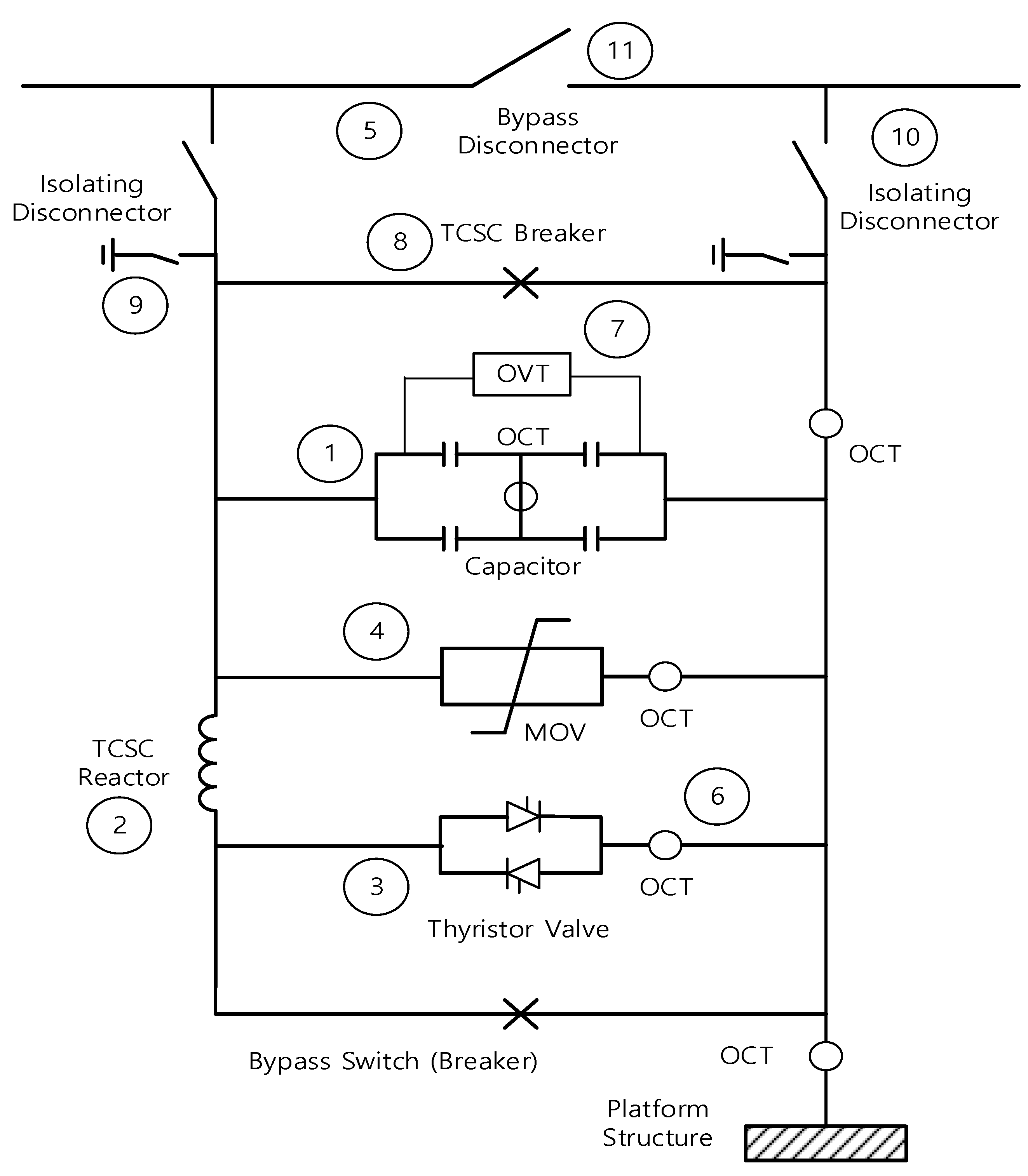
In addition, in preparation for the simultaneous failure of two nearby 765 kV transmission lines, 50% of the transmission line reactance is compensated in the normal state, with a maximum of 70% compensation for 10 s in case of failure, which significantly improves system stability and reduces restriction costs. Figure 3 shows the composition of the TCSC installed at the SJC and SYJ substations, and the roles of each part are as follows.
  • Series capacitor (1)
It is the main circuit component of the TCSC and is connected in series with the line. It is connected in series with the line, which is an inductive reactance component and serves to compensate for the line impedance through a capacitor.
  • Reactor (2)
It is an inductive reactance device connected in parallel with a series capacitor. It operates as a thyristor-controlled reactor (TCR) and is designed according to a specific resonance frequency to increase the capacitor voltage using the resonance characteristic of the series capacitor.
  • Thyristor valve (3)
It controls the current flowing to the reactor by increasing the capacitor voltage through the thyristor firing angle control and performs a bypass control to protect the series capacitor in case of overcurrent due to line failure.
  • MOV (4)
It protects the series capacitor and valve from overvoltage in case of a power transmission line failure.
  • Bypass switch (5)
As a circuit breaker, it maintains an open state during the normal operation of the series capacitor and closes it in case of line failure to protect the series capacitor, valve, and MOV.
  • OCT (Optic Current Transducer) (6), OVT (Optic Voltage Transducer) (7)
It measures the capacitor voltage for current measurement and thyristor control.
  • TCSC Breaker (8), Isolating DS (Disconnect Switch) (9,10), Bypass DS (11)
It is a switching device for insulating and bypassing the series capacitor during maintenance and operation and for connecting and disconnecting the TCSC equipment from the line.

2.2. TCSC Control Operation

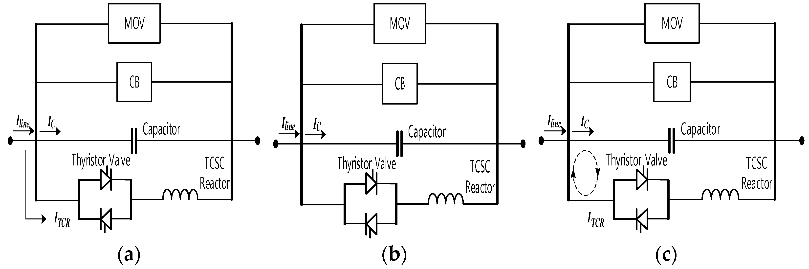
In TCSC, the operation mode is classified as follows according to the thyristor control. Figure 4 shows the various TCSC control modes.
  • Bypassed-thyristor mode
It is a control mode that completely conducts the thyristor firing angle at 90°. Because reactors are small compared with series capacitors, most of the line current flows into the thyristor-controlled reactor. This mode is used to protect the series capacitors from fault currents in the event of a line fault.
  • Blocked-thyristor mode
The firing angle of the thyristor is set to 180°, or the firing signal is blocked so that the line current flows only through the series capacitor.
  • Capacitor vernier mode
The firing angle of the thyristor should be between 90° and 180° and a parallel resonance between the series capacitor and the reactor should be made. Because the TCSC has inductive and capacitive characteristics based on the size of the firing angle and is mainly used for impedance compensation control of transmission lines, the capacitive region is used, and the inductive region is not used.

2.3. TCSC Replica Controller

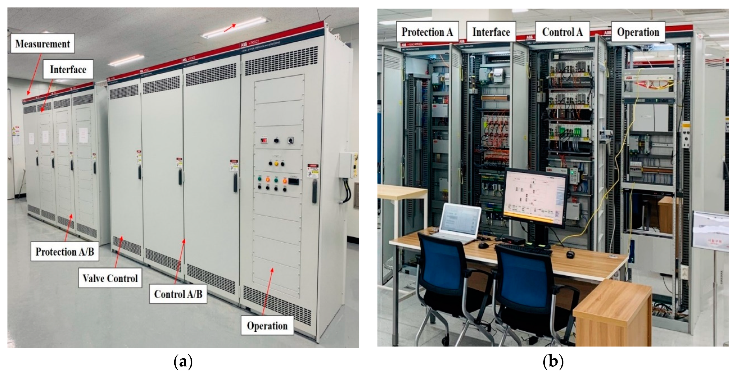
TCSC replica controller is 100% identically designed, manufactured, and operated together with RTDS except for the duplication of the on-site controller and the control and protection system. In conjunction with RTDS, pre-commissioning was performed on more than 100 test items before the on-site testing of the on-site controllers. It is used for reproducibility and causes an analysis of problems occurring in the field, analysis of the interaction with nearby facilities, and a verification before updating the on-site controllers. Figure 5a shows the TCSC field controller installed in the SYJ substation, and Figure 5b shows the replica controller installed in the laboratory [19,20,21,22,23].

3. Detailed Review Cases

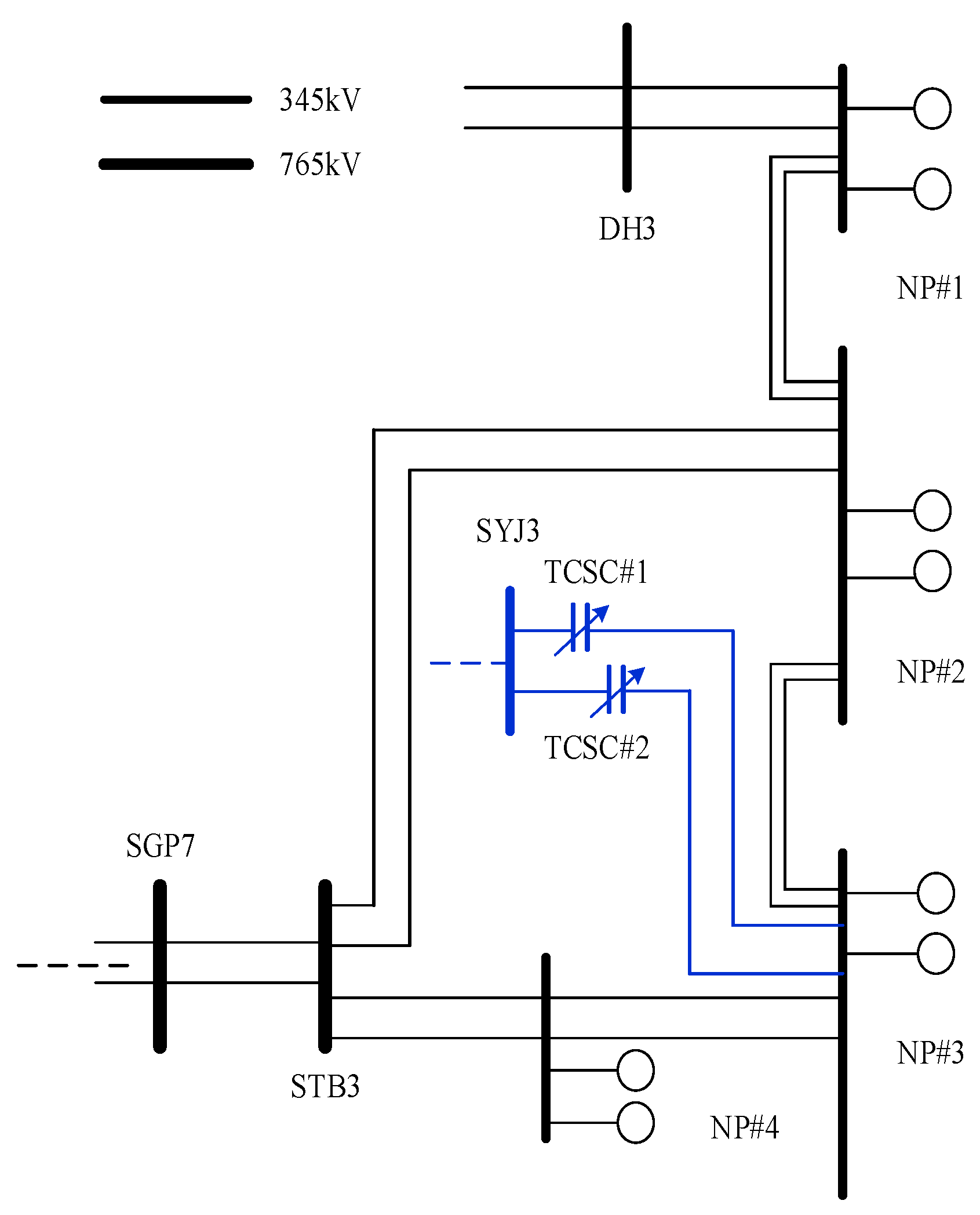
To investigate the effect of relocation when changing the TCSC outgoing line, the RTDS experiment using the TCSC replica controller was conducted to analyze the appropriateness of control and the possibility of SSTI (Sub Synchronous Torsional Interaction) occurrence through the electrical damping of the connected busbar. In addition, the mechanical damping of the generator was analyzed in advance. Figure 6 shows a simplified single-line diagram of the East Coast for relocation review [24,25,26,27,28]. Table 1 shows the impedance changes due to line impedance.

3.1. Scenarios for Control Adequacy Review

To review control adequacy, experiments were conducted on TCSC replicas and RTDS nationwide systems for maximum load in the 2022 summer operation plan, steady state operation of TCSC, boost factor step response, and instantaneous output increase control operation in the case of a 765 kV failure. TCSC’s X C is designed according to the X L of the existing transmission line; however, because the X L changes when it is relocated, the controller response performance may be affected by the suitability of control in the normal state and the system robustness of the connection location. The boost factor steps the response and analyzes the dynamic control performance in the case of failure. The boost factor is the ratio of the maximum achievable TCSC reactance to the minimum TCSC reactance.
Table 2 shows the installation and operating conditions of nearby STATCOM (STATic synchronous COMpensator) and SVC (Static Var Compensator).

3.1.1. Steady State Operation

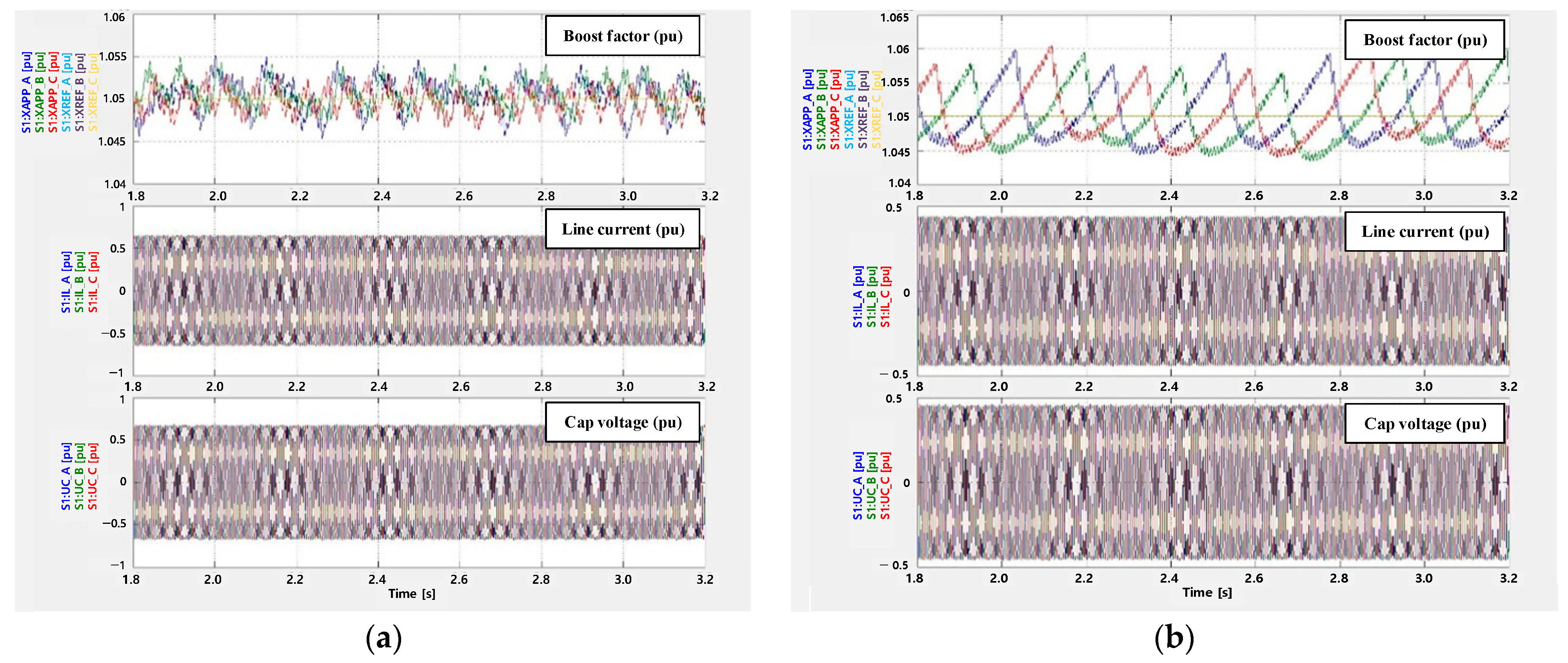
Figure 7 shows the comparison results of control adequacy before and after TCSC line relocation during the steady-state operation with a boost factor K = 1.05. During normal operation after relocation, a small vibration of 4 Hz level occurs, which is determined to be the effect of the gain of the internal controller due to a change in line impedance.

3.1.2. Boost Factor Step Response

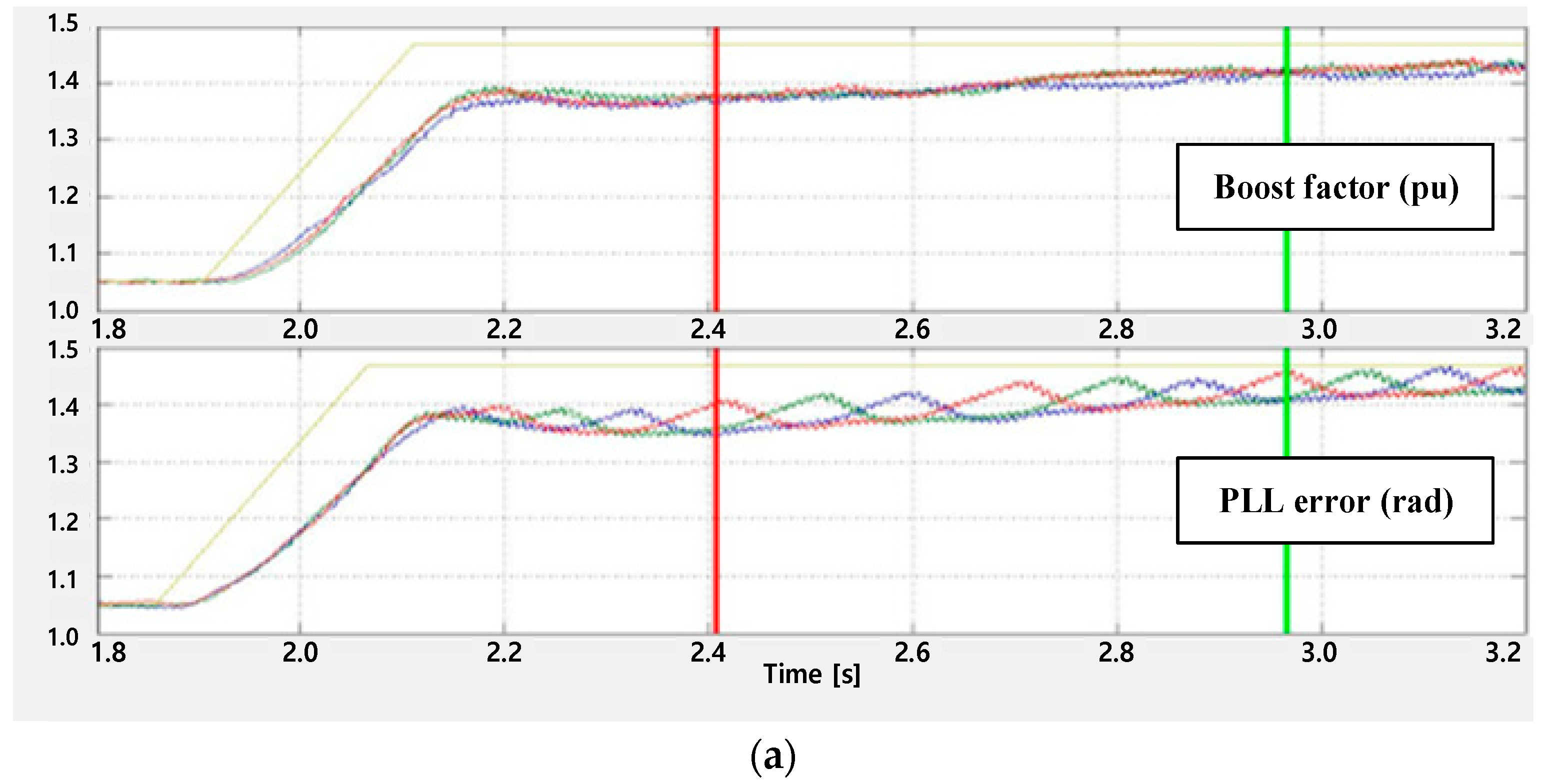
The boost factor K = 1.05 is changed to K = 1.47 during operation, as shown in Figure 8. The oscillation of 4 Hz due to the error in the internal PLL(Phase Locked Loop) controller occurs as in the steady state operation. This can be resolved through PLL controller gain correction in the future.

3.1.3. Instantaneous Output Increase Control Operation in Case of 765 kV Failure

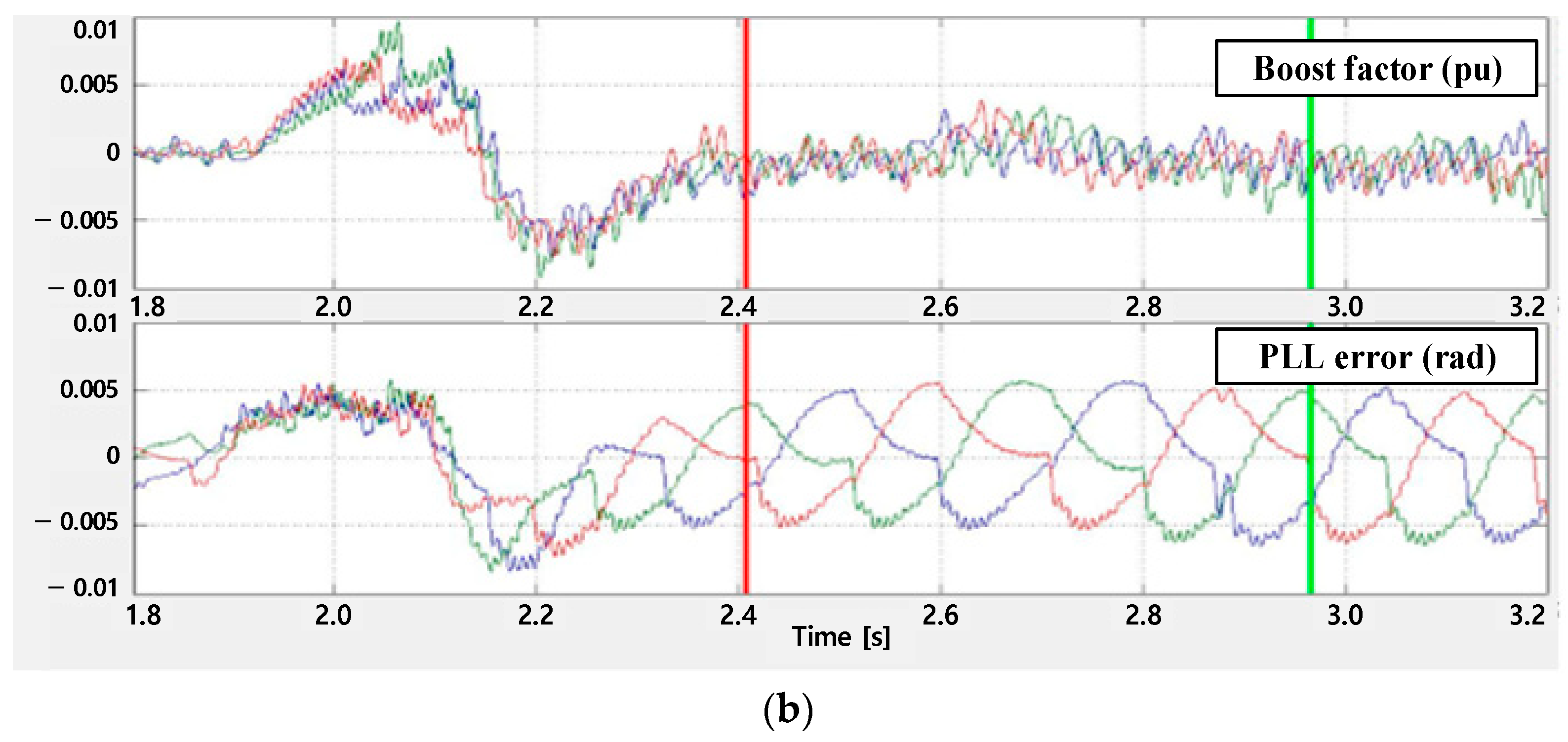
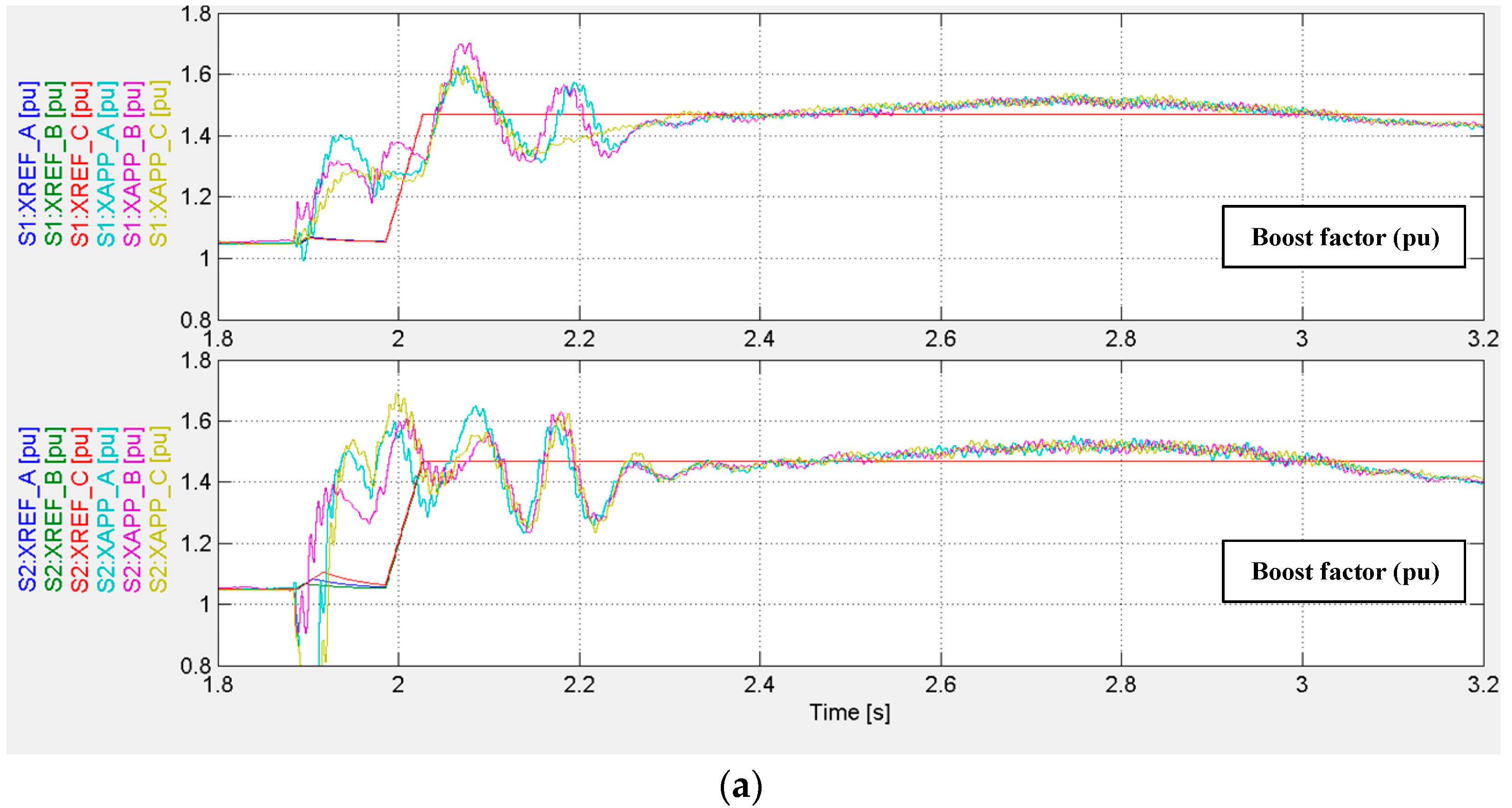
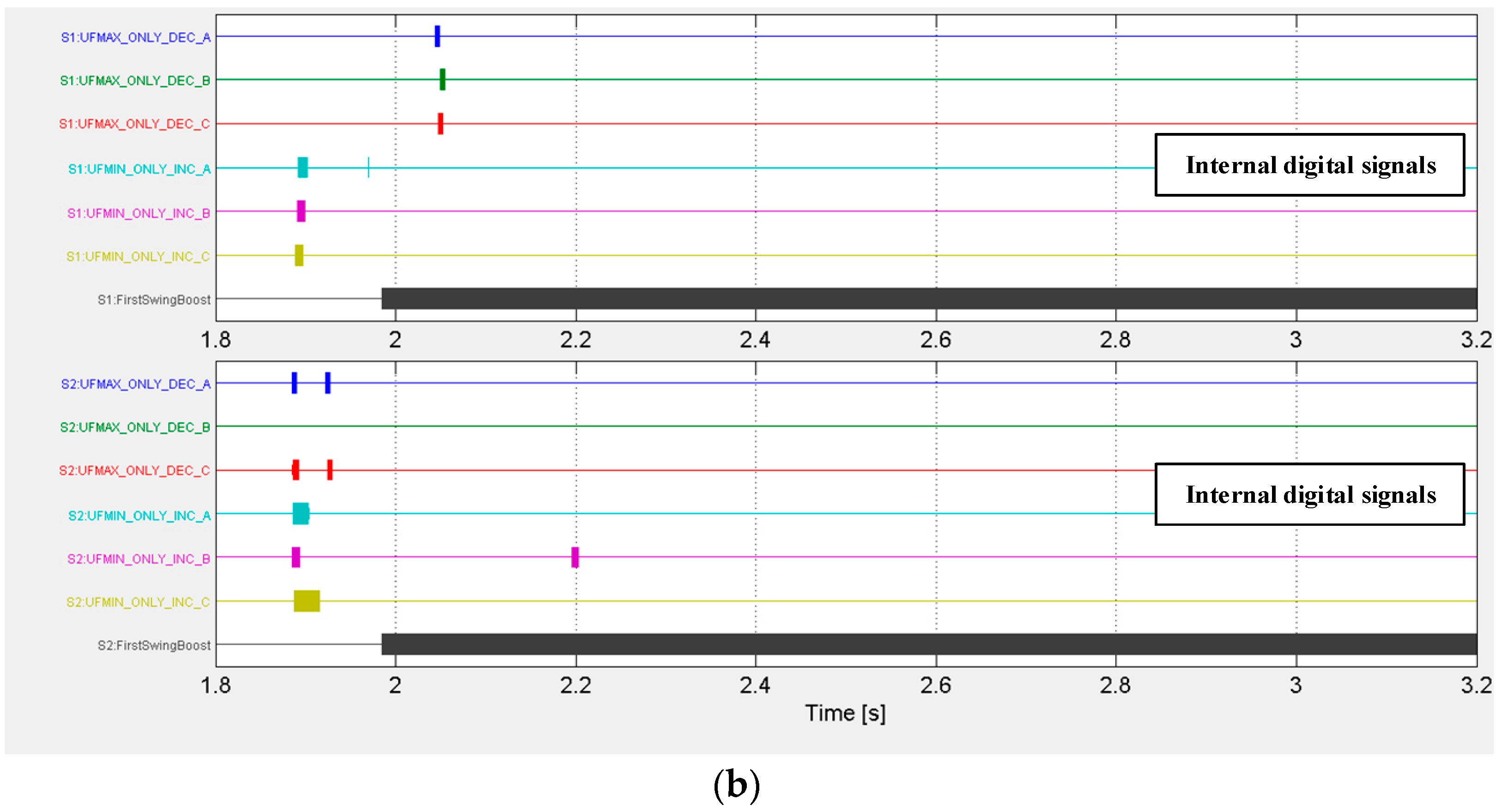
In the case of a 765 kV transmission line failure near the TCSC, as shown in Figure 9, the characteristics of the controller before and after relocation are indicated. Although there is a slight error in the transient state, there is no abnormal operation of control and protection, and the boost factor control and boost-up response characteristics by the SPS (Special Protection Scheme) signal are similar. Moreover, there is no bypass caused by the fault current in the case of the 765 kV fault.

3.2. Damping Analysis to Review the Possibility of SSTI Occurrence

The possibility of SSTI occurrence with generators in operation due to changes in the nearby system configuration was examined. SSTI requires a detailed review, as it may cause damage to the generator shaft because of the interaction between the generator turbine shaft and the power electronics-based control equipment. For the reason SSTI is affected by the electrical damping obtained from the associated generator, changing the connection location of the TCSC may cause the electrical damping change, thus necessitating a new analysis [29,30,31]. The review conditions were based on the maximum load of the 2022 summer operation strategy study data and the two connected TCSC replica controllers. The operating conditions of the adjacent parallel FACTS(Flexible AC Transmission System) are shown in Table 1 and simulated with a vendor’s SW model. The possibility of SSTI occurrence was reviewed through the UIF(Unit Interaction Factor) index and the electrical/mechanical damping analysis of TCSC, #1-#4NPs generators. There was no major topology change before and after the relocation. However, a review is essential because a reactor is connected to them.

3.2.1. UIF Index Analysis

The UIF expressed by Equation (2) is a value that quantitatively expresses the correlation between power electronic equipment and generators in terms of equipment rating and short-circuits capacity. If UIF > 0.1, a detailed study is recommended because of concerns about the possibility of SSTI [32]. There are a total of seven radial systems in which SYJ TCSC is connected in series with #NP1 and #NP3 generators, and their results are shown in Table 3.
UIF = P d c M V A i 1 S C L o u t S C L t o t a l 2
P d c : Active power transmission; M V A i : Generator rating; S C L o u t : Short-circuit capacity when generators subject to review are excluded; S C L t o t a l : Short-circuit capacity with generator under review (ohm).
In all cases, UIF < 0.1, implying that the possibility of SSTI occurrence was minimal.

3.2.2. Damping Analysis

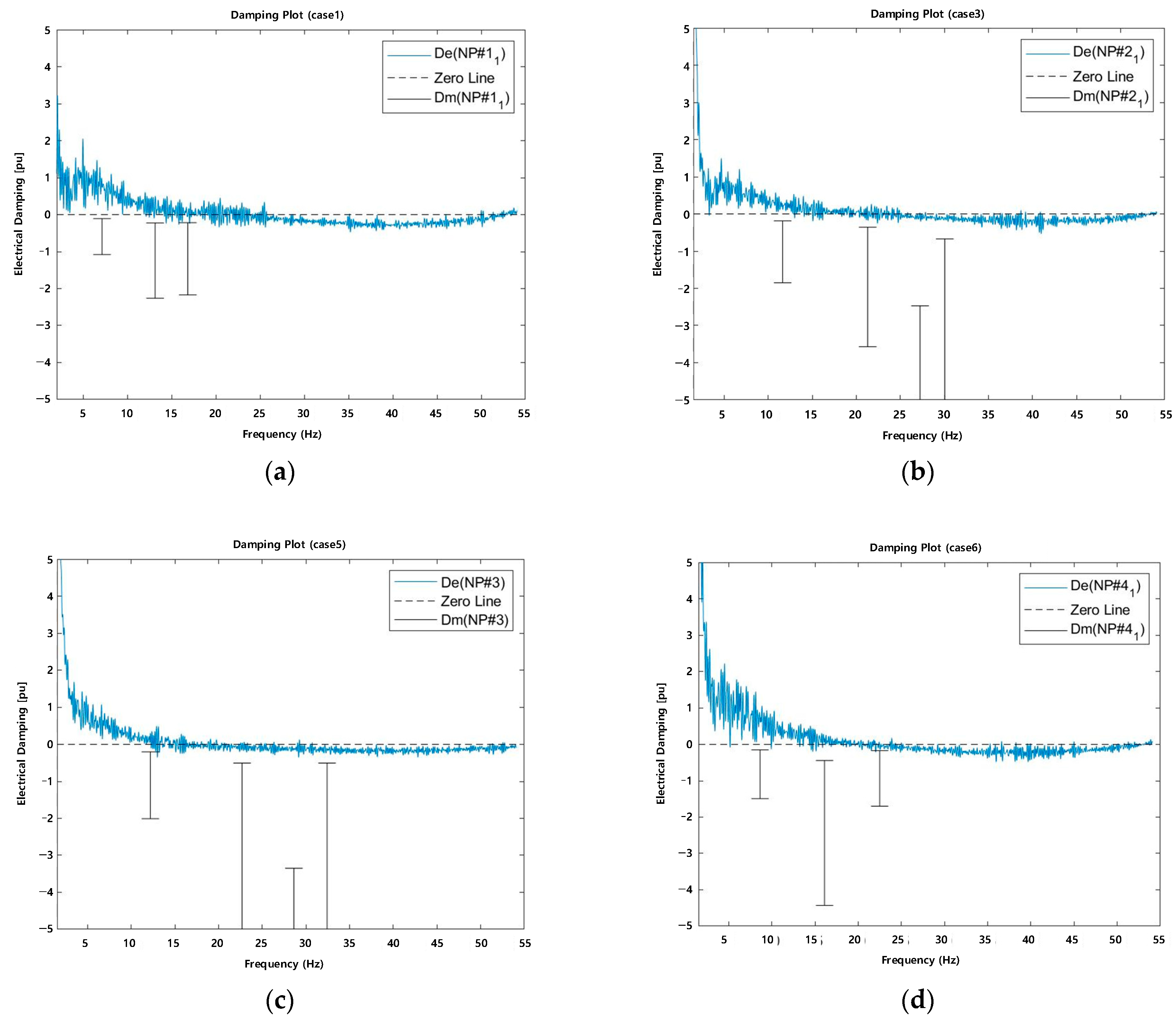
Although the UIF obtained a value smaller than 0.1 based on the review, the stability was analyzed in detail using the electrical damping characteristics of the generator and system, as well as the mechanical characteristics of the generator. Figure 10 shows the results of the damping analysis for four cases in which stable operation was achieved even after the configuration of the radial system. The stability was determined through the magnitude of the mechanical and electrical damping at the natural vibration frequency of the generator ( D m > D e D m D e > 0 ) .
Based on the detailed analysis of the damping, although the electrical damping has a negative value in some frequency domains, the possibility of SSTI occurrence is very low because there is a sufficient margin with the mechanical damping.

4. Conclusions

This study reviewed the possibility of control adequacy and the interaction of nearby generators due to the line impedance change of TCSC installed and operated in Korea’s power system through replica controller and RTDS whole grid simulation. According to the results of the normal operation, step response, and 765 kV transmission line failure, the required instantaneous power increase performance of the system is normal, but a small oscillation of 4 Hz occurs in the steady state, so it is necessary to modify some of the controller parameters in cooperation with the manufacturer. The possibility of SSTI with nearby generators is low due to the electro-mechanical damping analysis, but it is necessary to review the interaction with new generators and large-capacity LCC HVDC and TCSC operation strategies in detail.

Author Contributions

Conceptualization, H.-K.K., H.-I.K. and J.-H.S.; methodology, H.-K.K. and J.-Y.S.; software, S.-C.O. and J.-Y.S.; validation, H.-K.K., S.-C.O. and J.-H.S.; formal analysis, H.-K.K. and J.-Y.S.; investigation, H.-K.K.; writing—original draft preparation, H.-K.K. and H.-I.K.; writing—review and editing, S.-C.O. and H.-I.K.; supervision, J.-H.S. All authors have read and agreed to the published version of the manuscript.

Funding

This research received no external funding.

Institutional Review Board Statement

Not applicable.

Informed Consent Statement

Not applicable.

Data Availability Statement

Not applicable.

Conflicts of Interest

The authors declare no conflict of interest.

Nomenclature

D Damping
D e Electric damping
D m Mechanical damping
DS Disconnect Switch
FACTS Flexible AC Transmission System
HVDC High Voltage Direct Current
I C Current flowing into the series capacitor
I l i n e Current flowing from the AC grid to the TCSC
I T C R Current flowing into the thyristor valve
K Boost factor
LCC Line Commutated Converter
MOV Metal Oxide Varistor
M V A i Generator rating
OCT Optic Current Transducer
OVT Optic Voltage Transducer
P Active Power
P d c HVDC power transfer
PLL Phase Locked Loop
Q Reactive Power
RTDS Real Time Digital Simulator
S C L o u t Excluded short-circuit capacity of generator
S C L t o t a l Total short-circuit capacity of generators
SSTI Sub Synchronous Torsional Interaction
STATCOM STATic synchronous COMpensator
SVC Static Var Compensator
TCSC Thyristor Controlled Series Capacitor
θ Angle difference between the sending and receiving ends
UIF Unit Interaction Factor
V 1 Sending end voltage
V 2 Receiving end voltage
XCCompensation impedance
X L Line impedance

References

  1. Kim, S.H.; Oh, H.; Moon, B. A Study on the Application of HVDC, FACTS System in the Northeast Power System of Korea. J. Int. Counc. Electr. Eng. 2011, 1, 437–440. [Google Scholar] [CrossRef] [Green Version]
  2. Shin, W.; Ko, M.; Ku, H.; Song, J.; Hur, K. Estimation of Structural Mechanical Damping in Multi-Mass of Turbine Generator for SSTI Study. J. Electr. Eng. Technol. 2022, 17, 1639–1650. [Google Scholar] [CrossRef]
  3. Jamhoria, S.; Srivastava, L. Applications of thyristor controlled series compensator in power system: An overview. In Proceedings of the 2014 International Conference on Power Signals Control and Computations (EPSCICON), Thrissur, India, 6–11 January 2014; pp. 1–6. [Google Scholar]
  4. Hingorani, N.G.; Gyugyi, L. Understanding FACTS: Concepts and Technology of Flexible AC Transmission Systems, 3rd ed.; PWiley-IEEE Press: New York, NY, USA, 2000. [Google Scholar]
  5. A matter of FACTS—Deliver More High Quality Power. Available online: https://tinyurl.com/2mzgarh8 (accessed on 22 December 2022).
  6. ENSG ‘Our Electricity Transmission Network: A Vision For 2020. Available online: https://tinyurl.com/2lgxjeyf (accessed on 22 December 2022).
  7. TCSC for Stable Transmission of Surplus Power from Eastern to Western India. Available online: https://tinyurl.com/2gal3uoe (accessed on 22 December 2022).
  8. Korea’s 9th Long-Term Transmission and Substation Facility Plan. Available online: https://tinyurl.com/2dmhe6rr (accessed on 22 December 2022).
  9. Damas, R.N.; Son, Y.; Yoon, M.; Kim, S.Y.; Choi, S. Subsynchronous Oscillation and Advanced Analysis: A Review. IEEE Access 2020, 8, 224020–224032. [Google Scholar] [CrossRef]
  10. Walker, D.N.; Bowler, C.E.J.; Jackson, R.L.; Hodges, D.A. Results of subsynchronous resonance test at Mohave. IEEE Trans. Power Appar. Syst. 1975, 94, 1878–1889. [Google Scholar] [CrossRef]
  11. Bahrman, M.; Larsen, E.V.; Piwko, R.J.; Patel, H.S. Experience with HVDC—Turbine-Generator Torsional Interaction at Square Butte. IEEE Trans. Power Appar. Syst. 1980, PAS-99, 966–975. [Google Scholar] [CrossRef]
  12. Adams, J.; Carter, C.; Huang, S.-H. ERCOT experience with Sub-synchronous Control Interaction and proposed remediation. In Proceedings of the PES TD 2012, Orlando, FL, USA, 7–10 May 2012; pp. 1–5. [Google Scholar]
  13. Saad, H.; Fillion, Y.; Deschanvres, S.; Vernay, Y.; Dennetière, S. On Resonances and Harmonics in HVDC-MMC Station Connected to AC Grid. IEEE Trans. Power Deliv. 2017, 32, 1565–1573. [Google Scholar] [CrossRef]
  14. Saad, H.; Dennetière, S.; Clerc, B. Interactions investigations between power electronics devices embedded in HVAC net-work. In Proceedings of the 13th IET International Conference on AC and DC Power Transmission (ACDC 2017), Manchester, UK, 14–16 February 2017; pp. 1–7. [Google Scholar]
  15. Padiyar, K.R.; Kulkarni, A.M. Analysis of Subsynchronous Resonance. In Dynamics and Control of Electric Transmission and Microgrids; John Wiley & Sons Ltd.: Hoboken, NJ, USA, 2019; pp. 341–389. [Google Scholar] [CrossRef]
  16. Zheng, R.; Joseph, T.; Wang, S.; Liang, J. A control strategy for TCSC to mitigate SSR with local measurements. In Proceedings of the 13th IET International Conference on AC and DC Power Transmission (ACDC 2017), Manchester, UK, 14–16 February 2017; pp. 1–6. [Google Scholar]
  17. Ängquist, L. Synchronous Voltage Reversal Control of Thyristor Controlled Series Capacitor; Trita-ETS; Royal Institute of Technology: Stockholm, Sweden, 2002; p. 246. [Google Scholar]
  18. Dynamical Performance of TCSC Schemes. Available online: https://tinyurl.com/2g8w2jfq (accessed on 22 December 2022).
  19. Wang, Y.; Syed, M.H.; Guillo-Sansano, E.; Xu, Y.; Burt, G.M. Inverter-Based Voltage Control of Distribution Networks: A Three-Level Coordinated Method and Power Hardware-in-the-Loop Validation. IEEE Trans. Sustain. Energy 2020, 11, 2380–2391. [Google Scholar] [CrossRef] [Green Version]
  20. Cowan, I.L.; Marshall, S.C.M. Installation and interfacing HVDC control replicas at the national HVDC centre. In Proceedings of the 15th IET International Conference on AC and DC Power Transmission (ACDC 2019), Coventry, UK, 5–7 February 2019; pp. 1–6. [Google Scholar]
  21. Best Paths. Final Recommendations for Interoperability of Multivendor HVDC. Available online: http://www.bestpaths-project.eu/contents/publications/d93--final-demo2-recommendations--vfinal.pdf (accessed on 8 November 2022).
  22. Park, I.K.; Lee, J.; Song, J.; Kim, Y.; Kim, T. Large-scale AC/DC EMT Level System Simulations by a Real Time Digital Simulator (RTDS) in KEPRI-KEPCO. KEPCO J. Electr. Power Energy 2017, 3, 17–21. [Google Scholar]
  23. Hur, K.; Lee, J.; Song, J.; Ko, B.; Shin, J. Advanced Real Time Power System Simulator for Korea Electric Power Systems: Challenges and Opportunities. IEEE PES. 2018. Available online: http://site.ieee.org/pesitst/files/2018/08/2018-Panel-1.pdf (accessed on 8 November 2022).
  24. CIGREWorking Group B4.38. Modeling and Simulation Studies to Be Performed during the Lifecycle of HVDC Systems; CIGRE Technical Brochure: Paris, France, 2013. [Google Scholar]
  25. Kotsampopoulos, P.; Georgilakis, P.; Lagos, D.T.; Kleftakis, V.; Hatziargyriou, N. FACTS Providing Grid Services: Applications and Testing. Energies 2019, 12, 2554. [Google Scholar] [CrossRef] [Green Version]
  26. Ou, K.J.; Li, H.Y. Function and Dynamic Performance Test of the Updated Tian-Guang HVDC Control and Protection System. Adv. Mater. Res. 2012, 516–517, 1527–1530. [Google Scholar] [CrossRef]
  27. Guay, F.; Chiasson, P.; Verville, N.; Tremblay, S.; Askvid, P. New hydro Quebec real time Simulation interface HVDC commissioning studies. In Proceedings of the International Conference on Power Systems Transients 2017 (IPST 2017), Seoul, Korea, 25–29 June 2017. [Google Scholar]
  28. Siddiqui, A.S.; Khan, M.T.; Iqbal, F. A novel approach to determine optimal location of TCSC for congestion management. In Proceedings of the 2014 6th IEEE Power India International Conference (PIICON), Delhi, India, 5–7 December 2014; pp. 1–6. [Google Scholar]
  29. Sun, D.; Xie, X.; Liu, Y.; Wang, K.; Ye, M. Investigation of SSTI Between Practical MMC-Based VSC-HVDC and Adjacent Turbogenerators through Modal Signal Injection Test. IEEE Trans. Power Deliv. 2017, 32, 2432–2441. [Google Scholar] [CrossRef]
  30. Pilotto, L.A.S.; Bianco, A.; Long, W.F.; Edris, A.-A. Impact of TCSC control methodologies on subsynchronous oscillations. IEEE Trans. Power Deliv. 2003, 18, 243–252. [Google Scholar] [CrossRef]
  31. Yan, G.; Jia, Q.; Liu, K.; Hu, W.; Wang, J. Impact of DFIG-Based WTs on Subsynchronous Oscillation Damping of SG Based on the Net Electrical Damping Method. J. Electr. Eng. Technol. 2021, 16, 725–736. [Google Scholar] [CrossRef]
  32. Interactions between HVDC Systems and Other Connections. Available online: https://tinyurl.com/2hws5fvm (accessed on 22 December 2022).
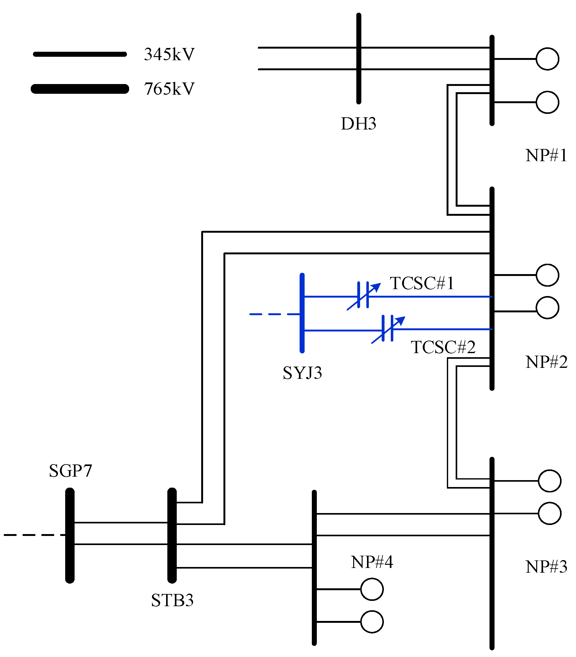
Figure 1. Simplified East Coast power grid configuration.
Energies 16 00722 g001
Figure 2. Transmission line impedance compensation and transmission capacity increase according to TCSC.
Energies 16 00722 g002
Figure 3. TCSC main components.
Energies 16 00722 g003
Figure 4. TCSC control mode. (a) Bypassed-thyristor mode. (b) Blocked-thyristor mode. (c) Capacitor vernier mode.
Energies 16 00722 g004
Figure 5. TCSC controller. (a) Actual controller in field operation. (b) Replica controller located in the lab.
Energies 16 00722 g005
Figure 6. Simplified East Coast schematic for relocation review.
Energies 16 00722 g006
Figure 7. Results of the review of steady state operation before and after relocation. (a) Before relocation. (b) After relocation.
Energies 16 00722 g007
Figure 8. Results of Boost factor in the step response test. (a) Boost factor. (b) Internal PLL error.
Energies 16 00722 g008aEnergies 16 00722 g008b
Figure 9. Instantaneous output increase control performance test results in case of 765 kV failure. (a) Boost factor in case of 765 kV failure, before relocation (top)/after relocation (bottom). (b) 765 kV failure TCSC internal control digital signal, before relocation (top)/after relocation (bottom).
Energies 16 00722 g009aEnergies 16 00722 g009b
Figure 10. Damping analysis results of generators capable of running in series. (a) Case1 NP#1_1 Generator damping analysis result. (b) Case3 NP#2_1 Generator damping analysis result. (c) Case5 NP#3 Generator damping analysis result. (d) Case6 NP#4_1 Generator damping analysis result.
Energies 16 00722 g010
Table 1. Line Impedance before and after relocation.
ItemsValuesUnit
BeforeAfter
Line lengthOverhead Line: 90.958Ov head Line: 90.003
Underground Cable: 1.5
km
Resistance0.0013640.001358Ω/km
Inductance0.5699430.86011Ω/km
Conductance0.0231940.023035mS/km
Table 2. FACTS installation and operation status near TCSC.
Installation LocationEquipmentVolume (Mvar)Operating Capacity (Mvar)
SYJ S/SSTATCOM±400100 (Inductive)
SCJ S/SSTATCOM±400−200 (Capacitive)
DH S/SSTATCOM±400200 (Inductive)
SJC S/SSVC−225~+6750
Table 3. UIF Screening results.
Case 1234567
Target generatorNP#1–1NP#1–2NP#2–1NP#2–2NP#3NP#4–1NP#4–2
UIF0.02400.00390.02270.00160.04690.06190.0114
Disclaimer/Publisher’s Note: The statements, opinions and data contained in all publications are solely those of the individual author(s) and contributor(s) and not of MDPI and/or the editor(s). MDPI and/or the editor(s) disclaim responsibility for any injury to people or property resulting from any ideas, methods, instructions or products referred to in the content.