Abstract
This paper addresses the use of a geothermal heat-sink to remove the heat released in domestic-sized single and double-effect water–LiBr absorption chillers operating in hot climates. This study is the continuation of a previous work, which demonstrated the operational constraints of these absorption chillers working in hot Algerian climate-zones. After localizing the non-operation zones for both systems, the thermo-physical properties of the soil at several depths are investigated for the implementation of the underground heat-exchanger. This heat-exchanger is connected to the condenser and the absorber of both systems, to supply cooling water at inlet temperatures of 33 °C in hot climate conditions, with ambient temperatures varying from 38 °C to 42 °C. The results show a steady operation for both absorption chillers in climate conditions which had not previously allowed the two systems to operate in water or air-cooled modes. A maximum coefficient of performance of 0.76 and 1.25 is obtained for single- and double-effect absorption cycles, respectively, with chilled water at 7 °C. The underground-tube length required is between 4.5 and 18 m, depending on the absorption-cycle configuration and the temperature of the chilled water.
1. Introduction
The increasing energy consumption of the residential sector in Algeria, with a total energy consumption of 17.6 MTep in 2019, is considered the main priority for the Ministry of Energy. It represents a 3% increase, compared to the year 2018 [1]. The energetic transition to renewables is essential to ensure a clean, less expensive, and uninterrupted energy production, especially in remote areas. The need for air conditioning is significantly increasing, especially in summer, when energy demand reaches its peak. The use of solar thermal energy to drive absorption chillers is an attractive way to save energy in air conditioning systems. However, certain serious operational constraints of absorption chillers limit their use in hot climate zones where the condenser and the absorber need to operate at high temperatures.
Several investigations reported the impact of the ambient temperature on the performance of absorption cooling cycles. Ketfi et al. [2] analyzed the performance of single- and double-effect water-LiBr absorption chillers in the conditions of five different climate zones in Algeria. The results showed a significant drop in the coefficient of performance (COP) and the cooling capacity when operating in hot climates. Neither of the chillers could operate in the Sahara’s hot climate, because of the limited solubility range of the aqueous solution of water–LiBr. Agrouaz et al. [3] investigated the feasibility of a 10-kW solar-absorption refrigeration system in the climatic conditions of six Moroccan cities. The coefficient of performance and solar fraction were calculated for each climate zone. The best performance was obtained in the Errachidia climatic zone, with an annual COP of 0.33 and a solar fraction of 30%. Merabti et al. [4] presented a study of a solar-evaporative cooling system operating by means of desiccation. The study was performed in the climate conditions of Tipaza, Algeria. The results showed that the system could control moisture and provide acceptable conditions of comfort, rendering it suitable for humid environments such as those of coastal cities in Algeria. A theoretical study of different solar cooling systems, namely, solar-absorption, solar-adsorption, photovoltaic and photovoltaic thermal systems was carried out in different climate conditions, and was presented by Mortadi et al. [5]. The solar-thermal performances of all systems were calculated to determine the most favorable system. The solar coefficient of performance (SCOP), levelized cost of cooling (LCOC), discounted payback period (DPP) and Life Cycle Climate Performance (LCCP) were simulated, using the EnergyPlus simulation tool. The results showed better performances when using the photovoltaic thermal-cooling system. Lu et al. [6] reported an experimental study carried out on a multi-energy absorption system for combined cooling and heating (ASCCH). The system was designed to operate in both cold-winter and hot-summer areas. The ASCCH was powered by solar energy, biomass, and natural gas. The coefficient of performance, heating, and cooling powers, along with the system pressure variation were calculated and presented. The coefficient of performance of the system was 0.88 at a summer ambient temperature of 32 °C. The authors also analyzed the economic and environmental impact of the system, using renewable energy sources to power it. They concluded that the annual operating cost for a typical household could be reduced by up to 46.8%, and, compared with conventional systems, CO2 emissions could be mitigated by approximately 44%. Camara et al. [7] developed a mathematical model to simulate the thermal performance of a double-acting solar collector (DASC) for daytime solar heating and nocturnal radiative cooling, coupled with a single-effect water–LiBr absorption–cooling system for use in hot regions. The absorption chiller developed a COP of 0.87, with a whole-system performance of 0.64 for Bamako climate conditions. An advanced absorption–cooling cycle driven by a multi-generation renewable heat source destined for remote areas was simulated by Kumar et al. [8]. An analysis was carried out to establish how system-component temperatures, combined with the ambient temperature, affected the performance of the system. The authors highlighted the negative impact of ambient temperature on the system performances, namely, in the coefficient of performance and the cooling power. Ghodbane et al. [9] presented a simulation study on the feasibility of an air conditioning system powered by parabolic trough solar collectors. Water was used as refrigerant in the ejector air-conditioning-cycle. The system was modelled to insure air conditioning in an 18-kW control room in Gassi-Touil in southern Algeria. The optical, thermal and exergy efficiency of the solar collector, the main ejector parameters, the coefficient of performance of the ejector air-conditioning subsystem, and the solar performance coefficient were accurately determined in different operating conditions. The main results showed a very important limitation of the cooling system in the hot climates of the Sahara Desert.
Geothermal energy sources could be used in four main applications: (i) heating applications [10,11,12], (ii) power generation [11,13,14], (iii) driving a geothermal heat pump for space air conditioning [10,15,16,17,18], and (iv) direct air refreshment (Canadian well) [19]. Lebbihiat et al. [20] reviewed the historical development, current utilization, practices, and opportunities regarding geothermal energy in Algeria. Benzaamaa et al. [21] presented an experimental and numerical analysis of an underground heat exchanger destined for air pre-conditioning of a building in the climate conditions of Oran (northern Algeria). The experimental implementation results were compared with those simulated under TRNSYS and FLUENT software. The results showed that the energy efficiency of the combined geothermal system was more significant in the arid zones (southern Algeria) and in the semi-arid zones. Hebbal et al. [22] presented an experimental investigation for geothermal cooling in an underground building in Ghardaïa, a city 600 km south of Algiers. The results were then compared with those obtained from an aboveground building. The energy savings for air conditioning purposes, especially in summertime, were considerable. Bassoud et al. [23] presented a study on the thermal behavior of a naturally ventilated old building built with adobe, with a compacted urban tissue known as Ksar. A thermal-comfort study was carried out, using the adaptive model ASHRAE-55 for populations of hot and arid regions in southern Algeria. The authors found that the basic natural materials used there in buildings were excellent thermal insulators for the severe ambient temperatures of the area.
Most of the studies presented above were devoted to the conversion of geothermal energy for heating and power applications [24,25,26]; however, few, if any, studies investigated the use of a geothermal heat-sink for dissipating the heat released in absorption-cooling systems. In this paper, a feasibility study is presented, using a geothermal heat-sink for the condenser and the absorber of low-capacity water–LiBr single- and double-effect absorption-cooling cycles operating in hot climates. In a previous study [2], the authors concluded that these absorption cycles were not able to operate in the conditions present in the hot climate zones in the Algerian Sahara. They recommended the use of an underground heat-exchanger to dissipate the heat released by the condenser and the absorber.
2. System Modelling
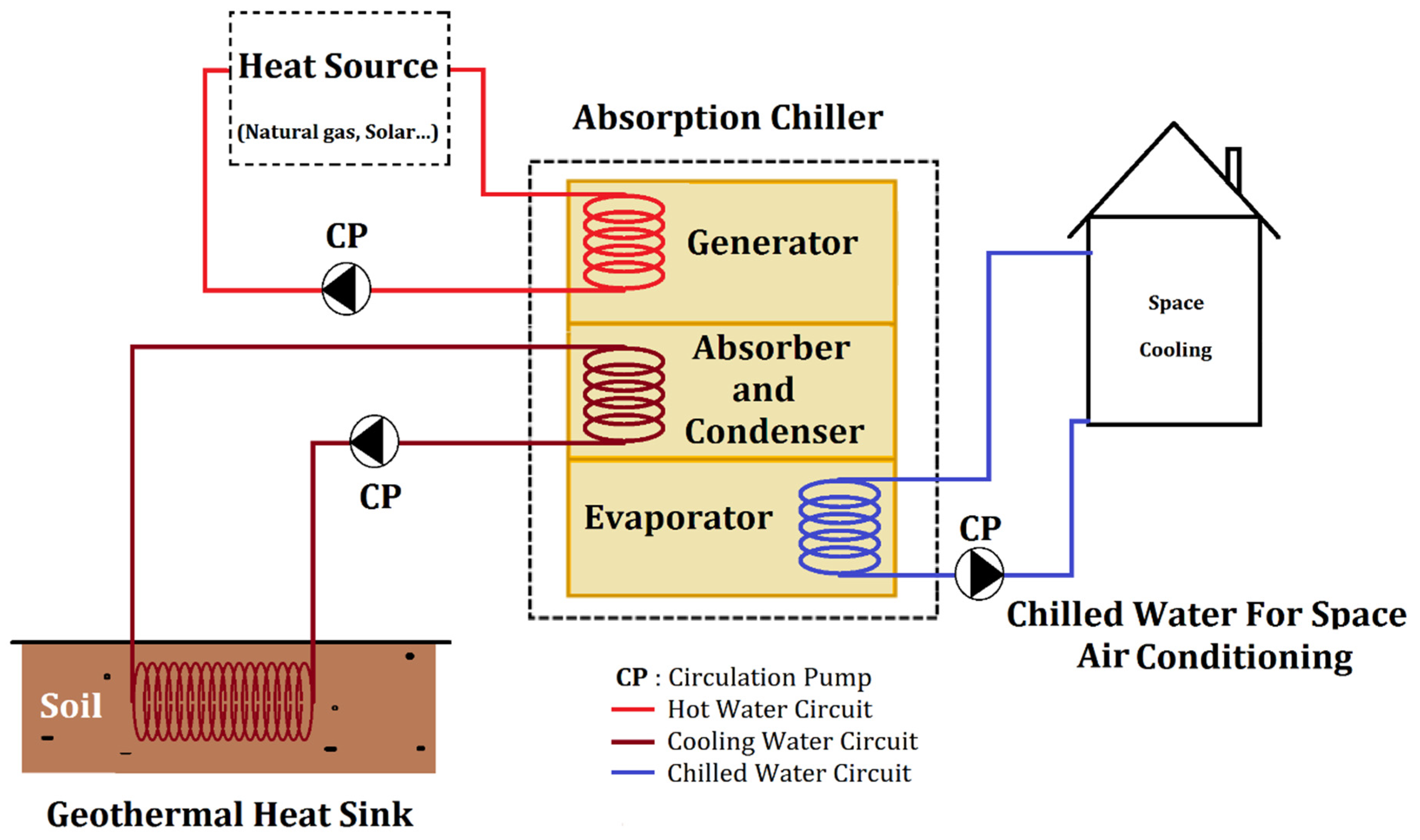
A schematic diagram of the absorption chillers and their external circuits is shown in Figure 1. Two domestic-sized water-LiBr single and double-effect absorption chillers were considered. Heat released by the absorber and the condenser of the chillers is dissipated into the soil via an underground heat-exchanger.
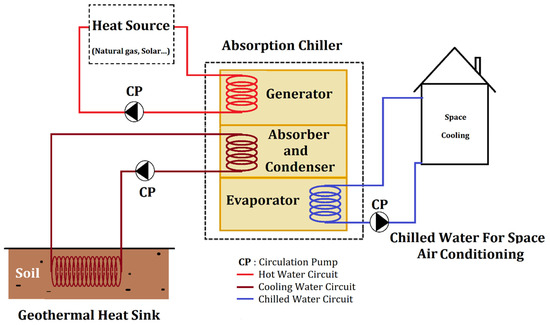
Figure 1.
Schematic of the geothermally cooled single/double-effect water–LiBr absorption systems.
2.1. Absorption-Chiller Modelling
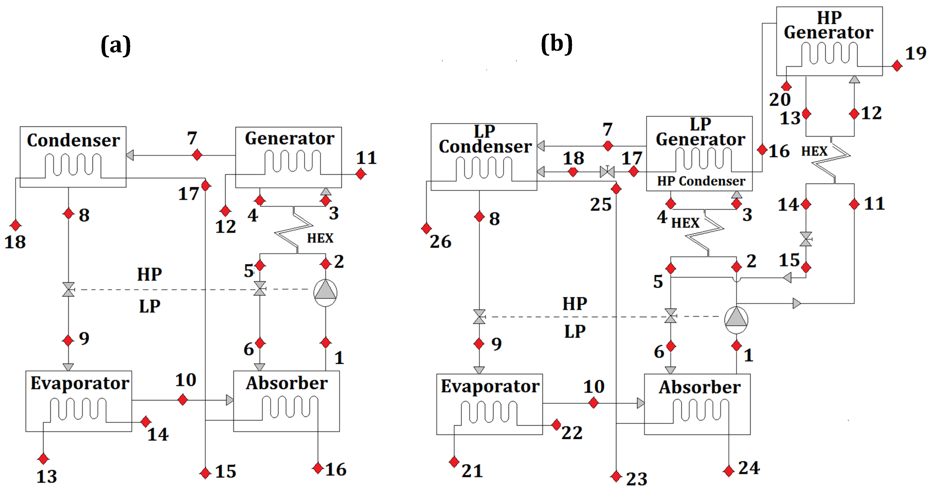
The modelling of the two absorption chillers and their thermal-performance parameters are presented, using the cycle configurations shown in Figure 2.
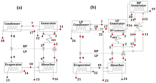
Figure 2.
Water–LiBr absorption cycles: (a) single-effect, (b) double-effect.
The basic mathematical model used for single- and double-effect water–LiBr absorption cycles is developed, based on the following assumptions: (i) steady state operation; (ii) pumping and throttling processes are isentropic; (iii) streams leaving the condenser and the evaporator are at saturation state; (iv) water–LiBr solution leaving the generator is at saturation state; and (v) temperature gradient between internal and external streams is set at 3 °C in all cycle components.
Mass- and Energy-Balances
Mass- and energy-conservation equations in the components of the single- and double-effect absorption cycles are expressed by the set of equations presented below [2], where the specific heat and enthalpy of the water–LiBr fluid mixture were calculated using the model reported by Patek [27].
Total mass conservation is given by [2]:
where and are, respectively, the inlet and outlet mass-flow-rates [kg/s] and is the LiBr solution concentration in weight [kgLiBr/kgsol].
The molar mass of the water–LiBr solution is written as [27]:
With and , respectively, the water and LiBr molar mass , and the LiBr molar concentration [mol/L], which is given by
The energy balance equation in the heat and mass exchangers of the absorption cycles is expressed as follows [2]:
where hi and ho are, respectively, the inlet and outlet enthalpies [kJ/kg], and is the heat duty [W].
The coefficient of performance is given by
where and are the cooling capacity and heat supplied in the generator [kW], respectively. is the pump work, which was neglected.
2.2. Underground Heat-Exchanger Modelling
The underground heat-exchanger is used to dissipate heat, which is released in the condenser and the absorber of absorption-cooling cycles, into the ground. The following assumptions were considered for the mathematical model:
- Soil temperature is considered constant around the tube.
- Thin wall is considered for the heat exchanger tube.
- Wall-tube temperature is maintained constant at soil temperature.
- Fluid temperature undergoes a variation only in the axial direction.
- Ground properties are constant.
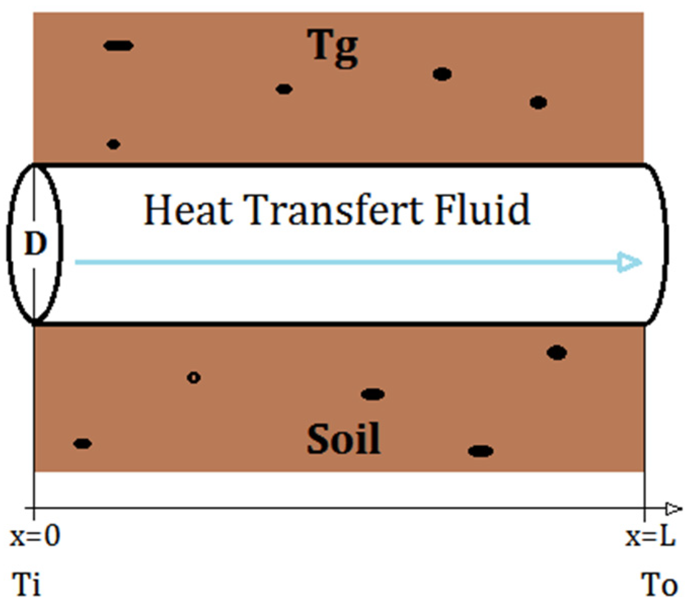
Figure 3 shows a simplified 2D heat flow inside a pipe surrounded by a constant soil temperature, Tg, and a constant mass-flow-rate, .
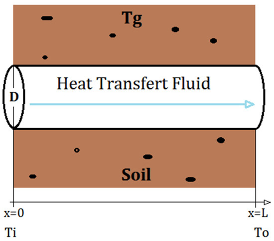
Figure 3.
Underground pipe section.
The analytical solution to this problem is easily determined by applying the heat balance equation between the heat transfer fluid and the ground. The exit temperature of the pipe is then expressed as follows [28]:
Tg is the ground temperature in [ °C], and are the inlet and outlet temperatures, respectively, in [ °C], in [kg/s] and in [J/kg·K] are the mass-flow-rate and the heat capacity of the heat transfer fluid, respectively.
For a desired outlet temperature, the length of the geothermal pipe can be calculated by
where h is the convective heat-transfer-coefficient of the flow in [W/m²·K], S is the geothermal pipe section in [m²] and P its circumference in [m].
2.3. Soil Temperature
The mean soil temperature is dependent on various parameters, namely, the ambient air temperature, Tmean, the temperature amplitude, Tamp, the depth, D, the day number, tyear, and the number of the coldest day in the year, tshift [29]:
From the above equation, the mean soil temperature is affected directly by the climate conditions and soil characteristics of the area (soil diffusivity ). The soil diffusivity α [m²/s] is calculated by:
where λ is the thermal conductivity of the soil and ρCp is its volumetric thermal capacity [30].
α = λ/ρCp
2.4. Case Study
According to the results reported by Ketfi et al. [2], the two absorption-cooling cycles investigated in the present work show severe limitations for operating in the hot climatic zones of southern Algeria. To overcome these limitations, geothermal ground is used as a heat-sink for dissipating the heat released by the absorption cycles at medium temperatures. The classification used for the Algerian climate was that reported by the National Centre for Integrated Building Studies and Research (CNERIB) and the National Office of Meteorology (ONM) in 2011 [31], and is shown in Figure 4.
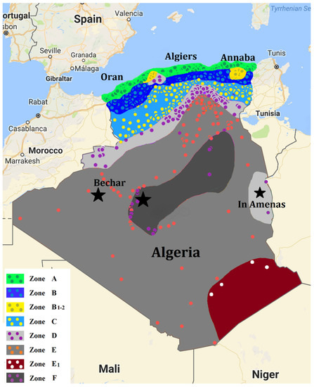
Figure 4.
Climate-zone classification according to CNERIB 2011 [31].
In this classification, eight zones, including two sub-zones, are proposed. These include two littoral zones (A and B), two transit zones (C and D) and two Saharan zones (E and F). The maximum reference temperature for each zone is summarized in Table 1.

Table 1.
Maximum reference temperature for climate zones in Algeria [31].
3. Results and Discussion
A performance analysis of the single- and double-effect absorption-cooling cycles was carried out for the eight climate zones defined in the previous section, taking into consideration the effect of maximum ambient temperatures. This meant that areas where the two absorption cycles were less efficient or could not operate could be identified. Subsequently, the nature of the soil of these areas was investigated and the depth from which the soil temperature remained constant was determined. Afterwards, a parametric study was performed to characterize the underground heat-exchanger used to dissipate the heat released by the absorption cycles into the ground. The performance of the absorption-cooling cycles coupled with an underground heat-exchanger is analyzed in the last part of the study.
3.1. Performance Analysis of the Single- and Double-Effect Absorption Chillers in Algerian Climate Zones
This parametric study differs from the previous one already reported by Ketfi et al. [2], in that the temperature gradient in the external circuits of the absorber and the condenser was reduced to 3 °C because of the addition of the underground heat-exchanger to remove the heat released in the absorber and the condenser. The performance of the two domestic-sized absorption chillers was analyzed in the ambient conditions of the eight climate zones in Algeria.
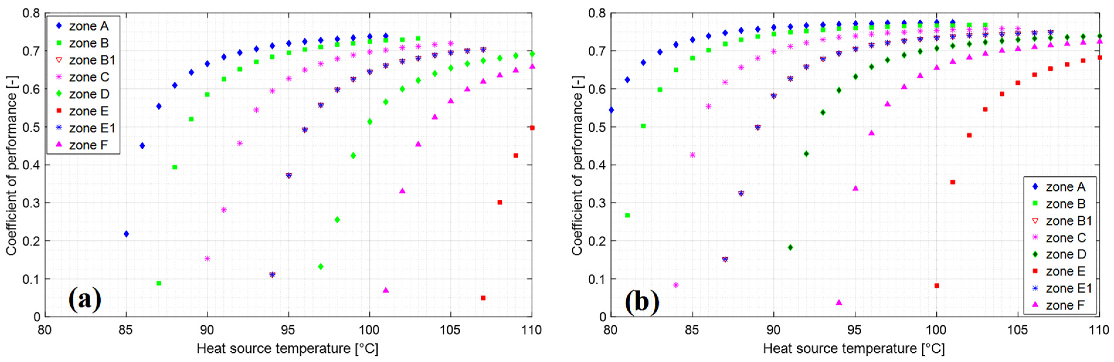
The coefficient of performance of the single-effect absorption cycle versus the heat-source temperature is presented in Figure 5 at two temperatures of chilled water, namely, Tcw = 7 °C and 12 °C. The variation of the COP is more pronounced at heat-source temperatures ranging from 95 °C to 102 °C in the climate zones A and B, and from 100 °C to 107 °C for the climate zones C and D. For climate zones E and F, the performance of the single-effect absorption cycle is significantly lower, even at high temperatures of the heat source. This is because of the high ambient temperature, in the order of 38 °C to 42 °C, which caused the water–LiBr solution to crystallize [32,33]. Raising the chilled-water temperature to 12 °C improved the cycle performance in all the eight climate zones, and allowed the absorption cycle to operate in the climate conditions of zone E.
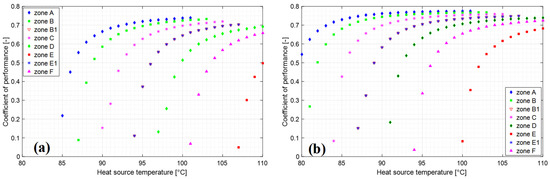
Figure 5.
Coefficient of performance versus heat-source temperature for single-effect absorption cycle at chilled-water temperatures of (a) 7 °C, and (b) 12 °C.
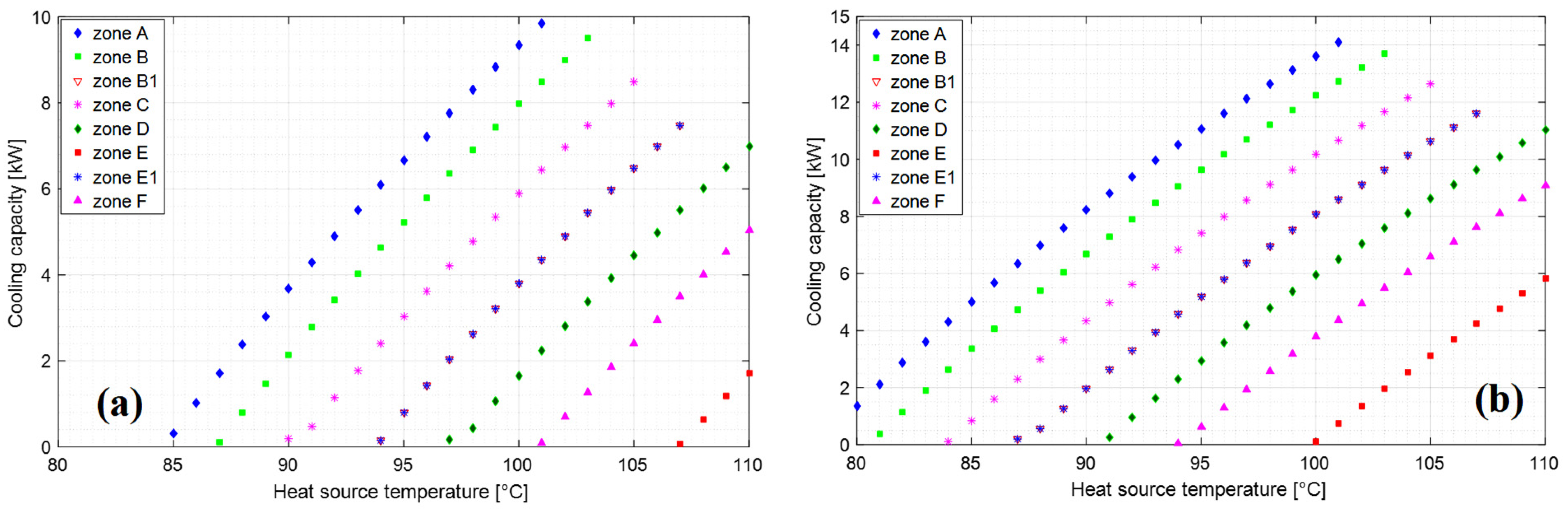
The cooling capacity of the single-effect absorption cycle for the eight climate zones is presented in Figure 6, at a chilled water temperature of Tcw = 7 °C and 12 °C. The single-effect absorption-cooling cycle can develop a cooling capacity of 7 to 10-kW at a heat- source temperature ranging from 95 °C to 100 °C in the conditions of climate zones A and B. Moreover, for climate zones C and D, the cycle can develop a cooling capacity of 8 and 7-kW at heat-source temperatures of 105 °C and 110 °C, respectively. However, for climate zones E and F, the single-effect absorption cycle could not deliver enough cooling capacity at Tcw = 7 °C, because of the high ambient temperatures in these zones. An improvement in cooling capacity was noted on increasing the chilled-water temperature from 7 °C to 12 °C. This measure allowed for normal operation in all climate zones except for climate zone E, where the high ambient temperature increased the crystallization risk of the water–LiBr solution [34,35,36,37].
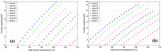
Figure 6.
Cooling capacity versus heat-source temperature for single-effect absorption cycle at chilled-water temperatures of (a) 7 °C, and (b) 12 °C.
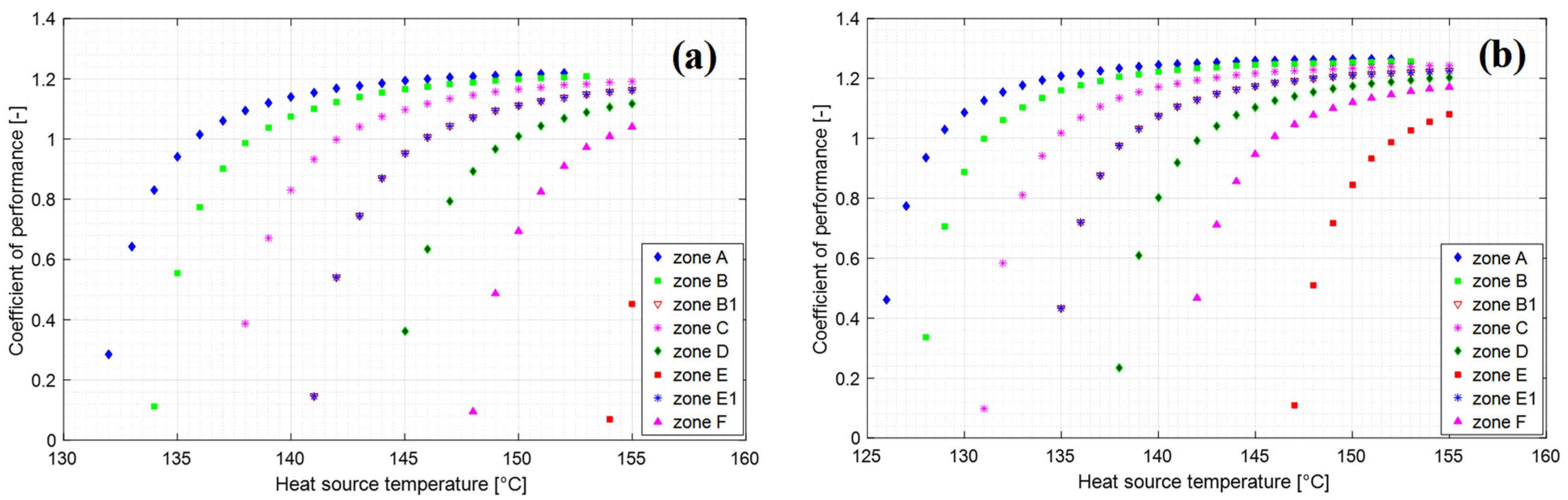
A second simulation was carried out in the eight climate zones of Algeria, using a domestic-sized double-effect absorption- cooling cycle. The results are shown in Figure 7 and Figure 8. The coefficient-of-performance (COP) variation versus the heat-source temperature is presented at chilled-water temperatures of 7 and 12 °C. It is noteworthy that the COP of the double-effect absorption cycle showed the same trend as in the single-effect absorption cycle, and could not operate in the climate conditions of zones E and F. This operational constraint in climate zone F could be overcome by raising the chilled-water temperature to 12 °C. This is, however, not feasible in the case of climate zone E, because of its high ambient temperatures.
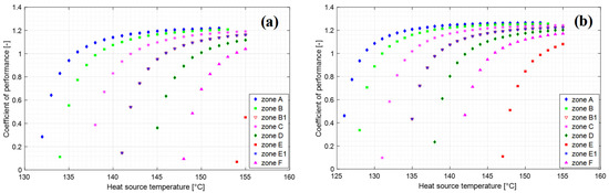
Figure 7.
Coefficient of performance versus heat-source temperature for double-effect absorption cycle at chilled-water temperatures of (a) 7 °C, and (b) 12 °C.
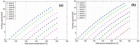
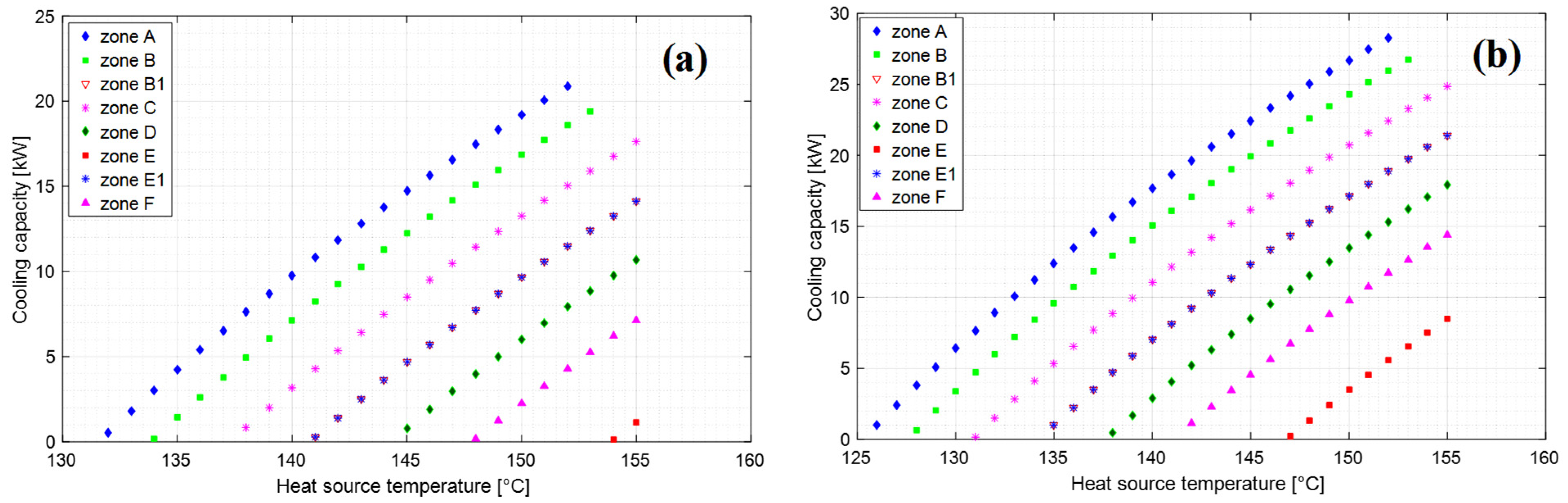
Figure 8.
Cooling capacity versus heat-source temperature for double-effect absorption cycle at chilled-water temperatures of (a) 7 °C, and (b) 12 °C.
At heat-source temperatures ranging from 150 °C to 155 °C, it is also worthy of note that the cooling capacity of the cycle is more significant than for single-effect absorption cycles. There is a maximum value of around 20-kW in the two climate zones A and B, and approximately 10 to 17-kW for the climate zones C and D. Increasing the chilled-water temperature to 12 °C allowed the absorption cycle to supply the foreseen cooling capacity in the climate conditions of zone F. However, the absorption-cooling cycle could not operate in climate zone E, because of the hot climate conditions.
3.2. Underground-Temperature Profiles for Climate Zones D, E and F
As seen from the previous results, the two absorption-cooling cycles investigated in this work could not operate properly in the weather conditions in climate zones D, E and F. To overcome these operational limitations, the ground was used as a heat-sink. An underground heat-exchanger was employed to dissipate into the ground the heat released in the condenser and absorber of the absorption cycles. Table 2 summarizes the data required for modelling the underground heat-exchanger in the three climate zones involved.
Table 2.
Data from the three climate zones which was used for modelling the operation of the underground heat-exchanger.
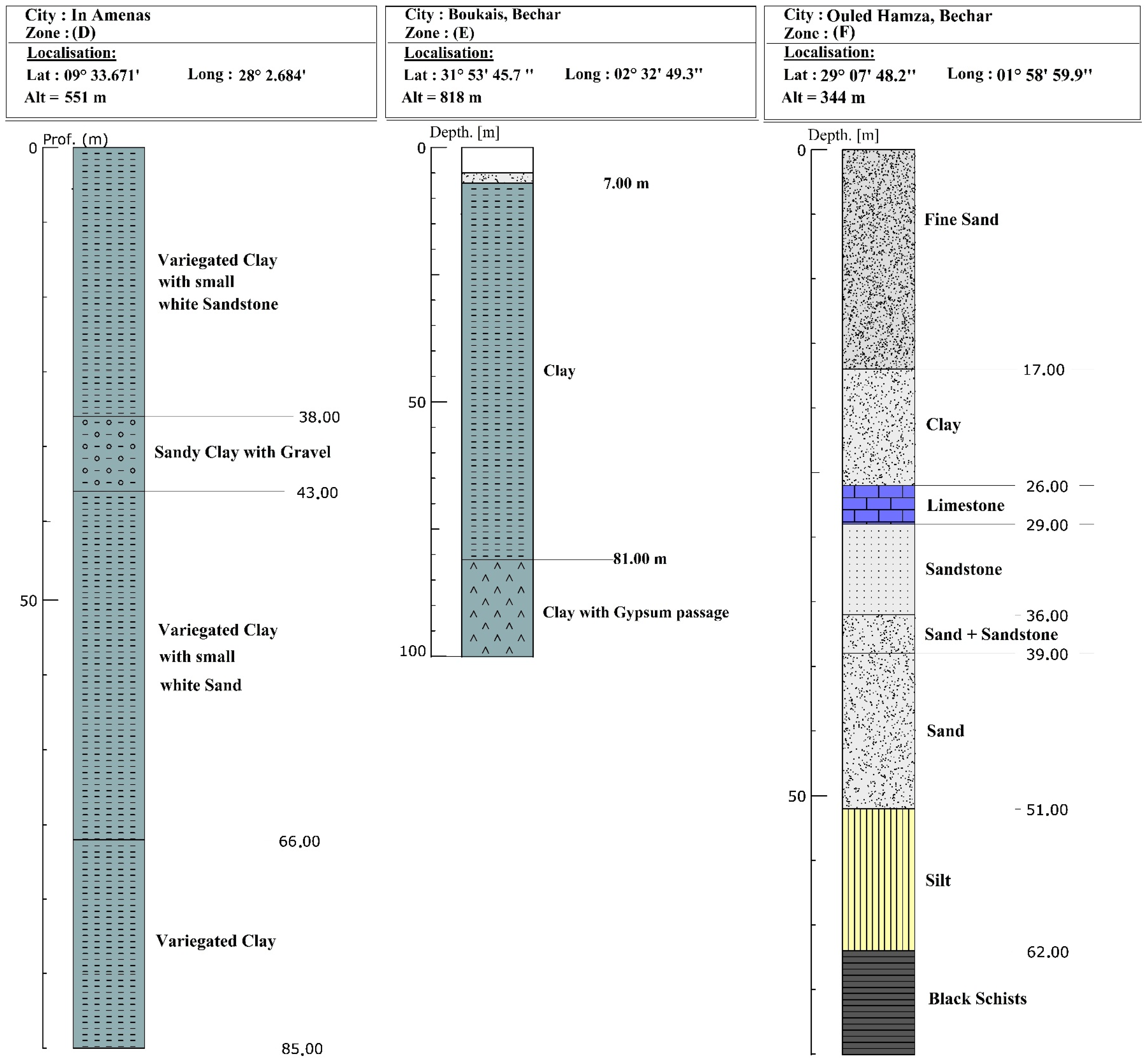
Soil diffusivity used in Equation (8) was determined using data supplied by the drill companies (borehole cuts) [30,38], and ground-temperature profiles were simulated at several depths in zones D, E, and F. This data is shown in Figure 9.
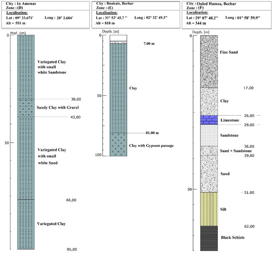
Figure 9.
Borehole cuts for the three climate zones D, E and F [38].
Notably, the soil quality depends on the site location and depth [39]. Yearly and seasonal soil-temperature profiles simulated at different depths are presented in Figure 10a, Figure 11a and Figure 12a for climate zones D, E, and F, respectively. The yearly soil-temperature profiles show a sinusoidal trend throughout the year and then stabilize at more profound depths [40].
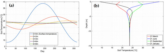
Figure 10.
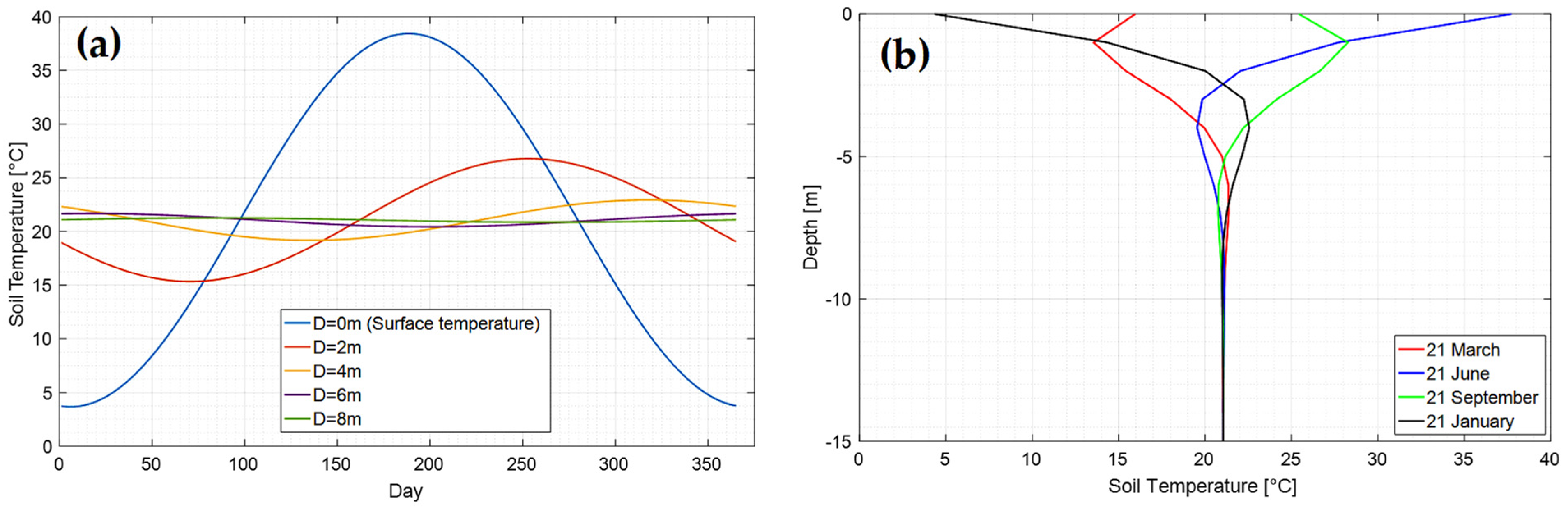
Soil-temperature profiles for several depths in climate zone D: (a) yearly, (b) seasonal.
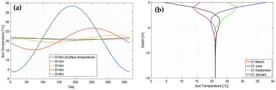
Figure 11.
Soil-temperature profiles for several depths in climate zone E: (a) yearly, (b) seasonal.
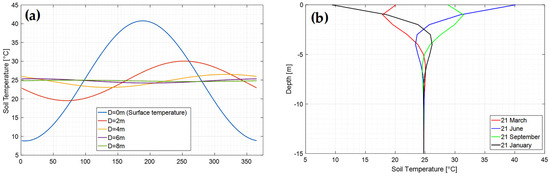
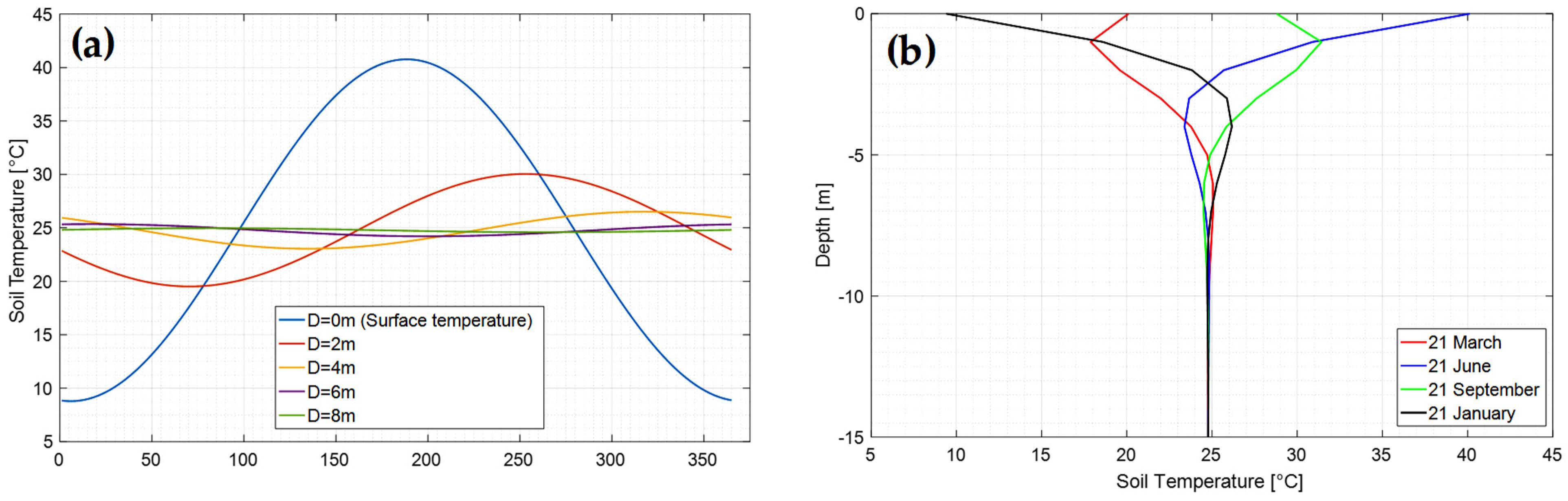
Figure 12.
Soi- temperature profiles for several depths in climate zone F: (a) yearly, (b) seasonal.
Figure 10b, Figure 11b and Figure 12b illustrate the seasonal soil-temperature profiles for the three climate zones D, E, and F, respectively. The stabilization temperature is around 23 °C, 21 °C and 25 °C at depths of 10, 8.5 and 9.5 m for the climate zones D, E, and F, respectively. Because of technical limitations, the depth of 2 m was selected for the present study, and corresponds to soil temperatures of approximately 28 °C, 22 °C and 27 °C in climate zones D, E, and F, respectively.
3.3. Parametric Study of the Underground Heat-Exchanger
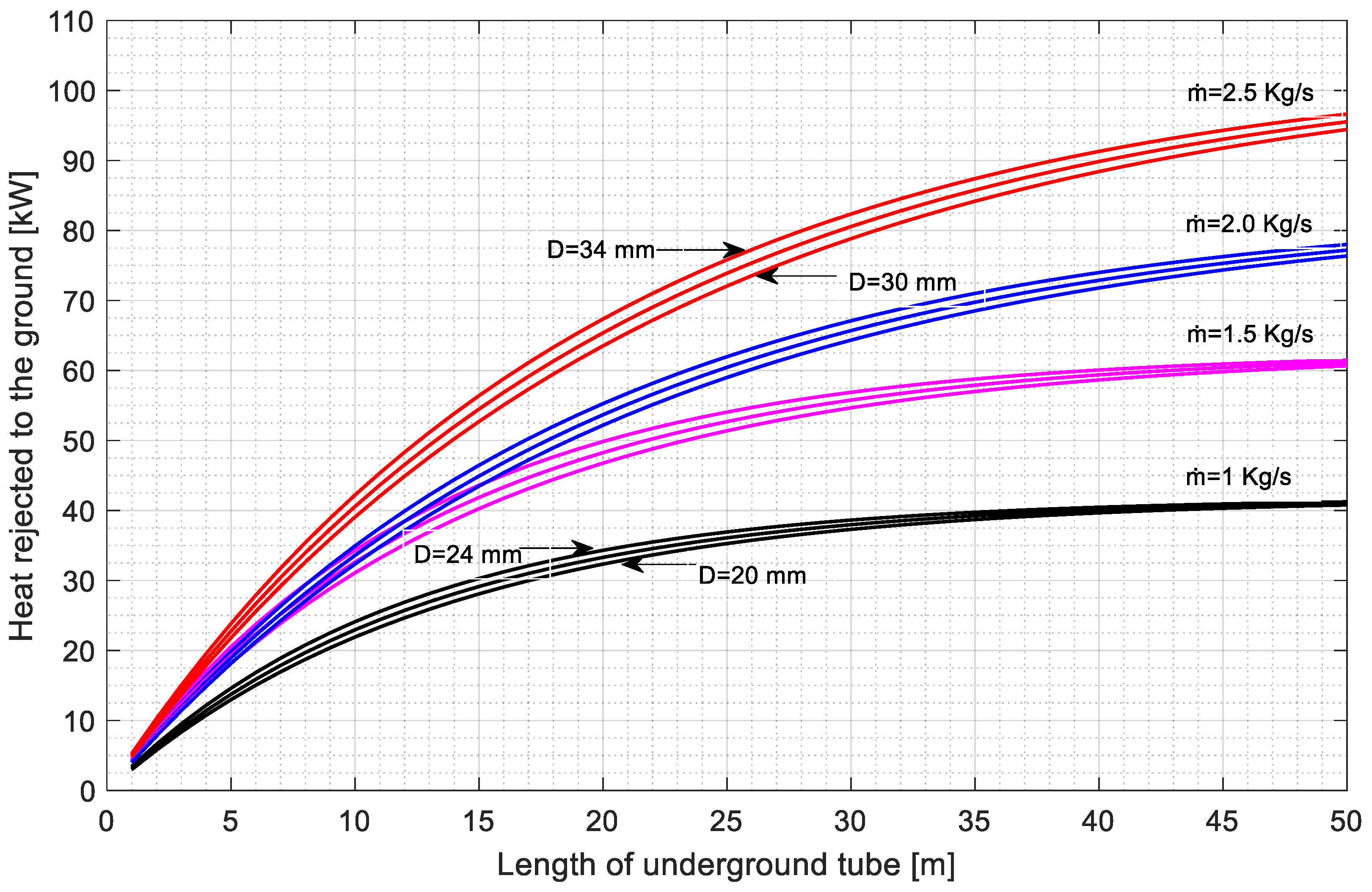
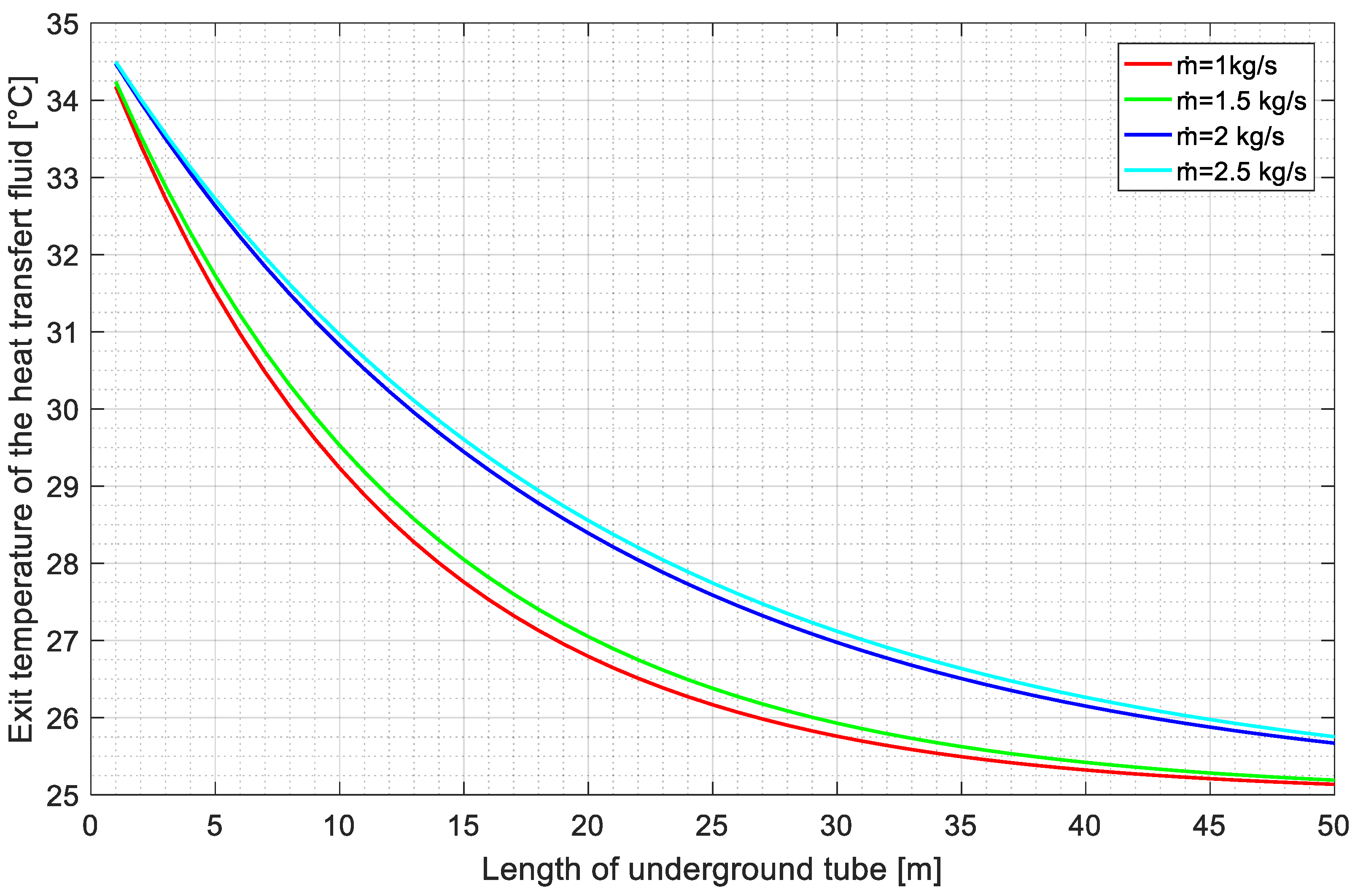
A parametric study of the underground heat-exchanger is presented in this section. Figure 13 shows the variation in the heat rejected to the ground versus the underground-tube length. Tube diameters from 20 to 24 mm and from 30 to 34 mm were assessed, and mass-flow-rates of the heat transfer fluid ranged from 1 to 2.5 kg/s. At these conditions, the heat-transfer-fluid velocity varied between 2.2 to 3.5 m/s, and corresponded to turbulent flow. The soil temperature was set at 25 °C and the water-inlet temperature at 35 °C. Noticeably, each curve reached a maximum of heat rejected into the ground at maximum tube length. The effect of mass-flow-rate was more pronounced with longer tubes, and the higher the mass-flow-rate, the higher the heat rejected. The effect of tube diameter was less significant. Figure 14 shows the exit temperature of the heat transfer fluid leaving the underground heat-exchanger versus the tube length at different mass-flow-rates. A significant decrease in the exit temperature of the heat transfer fluid is observed, either when the underground-tube length is extended or the mass-flow-rate is decreased.

Figure 13.
Heat rejected into the underground heat-exchanger versus tube length at different tube diameters and mass-flow-rates of the heat transfer fluid.
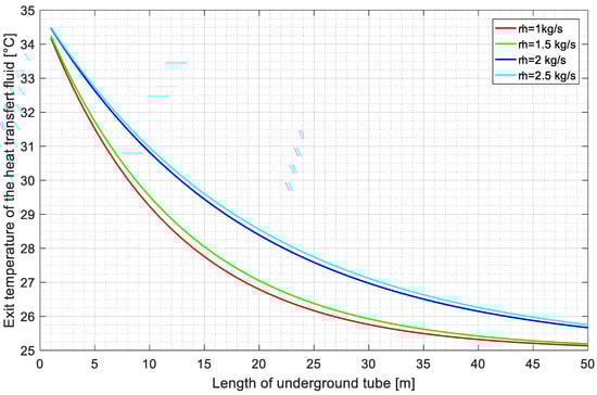
Figure 14.
Temperature of the heat transfer fluid leaving the underground tube versus tube length at different mass-flow-rates.
3.4. Performance Analysis of the Absorption-Cooling Cycles Connected to a Geothermal Heat-Sink
Absorption-cooling cycles connected to a geothermal heat-sink were simulated for the three climate zones in which the absorption cycle could not operate efficiently, or even not operate at all, i.e., zones D, E, and F. The internal and external streams in the absorber and condenser are considered to operate in counter-current flows; therefore, the temperature gradient (ΔT) between these streams was set at 3 °C for both components.
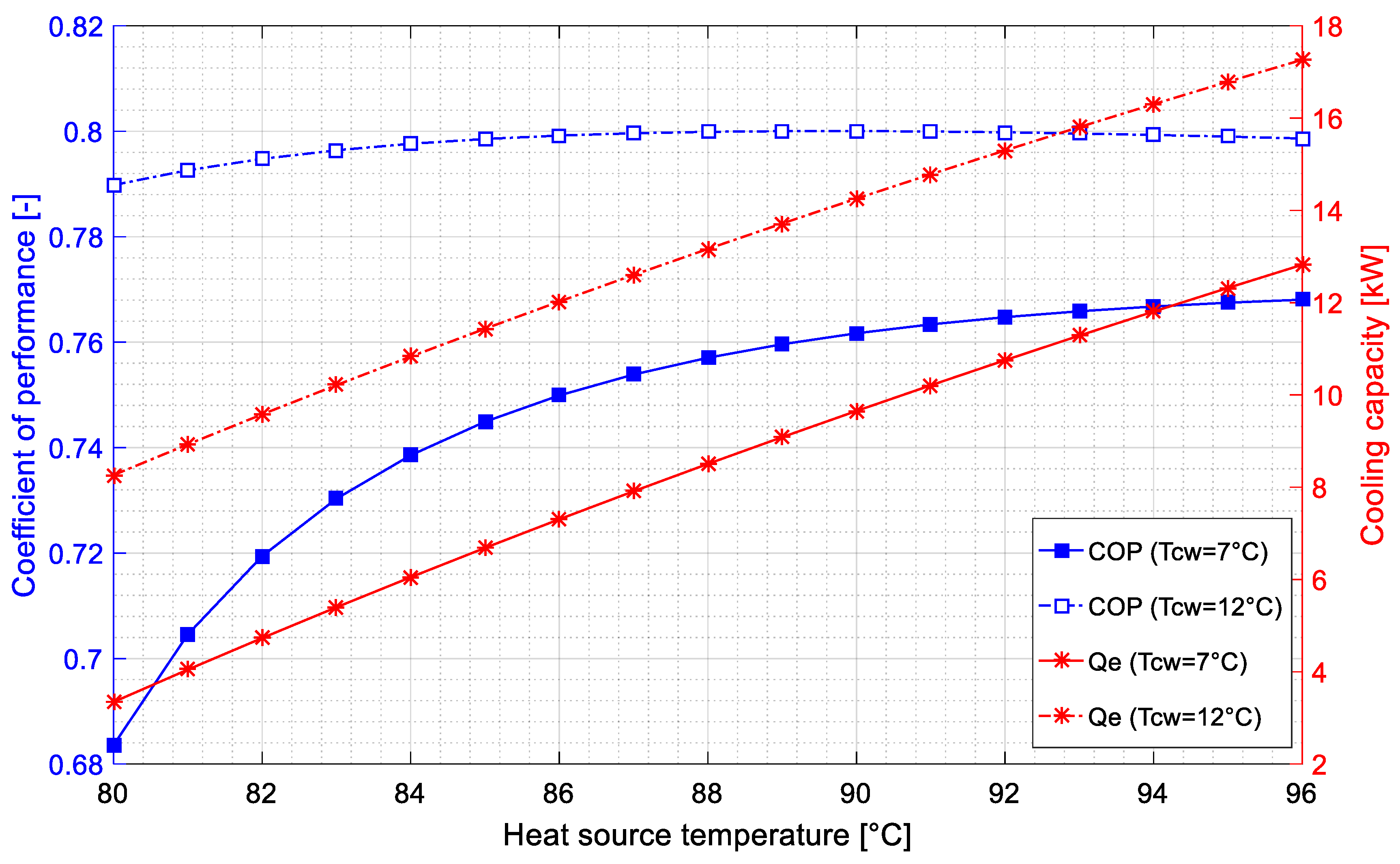
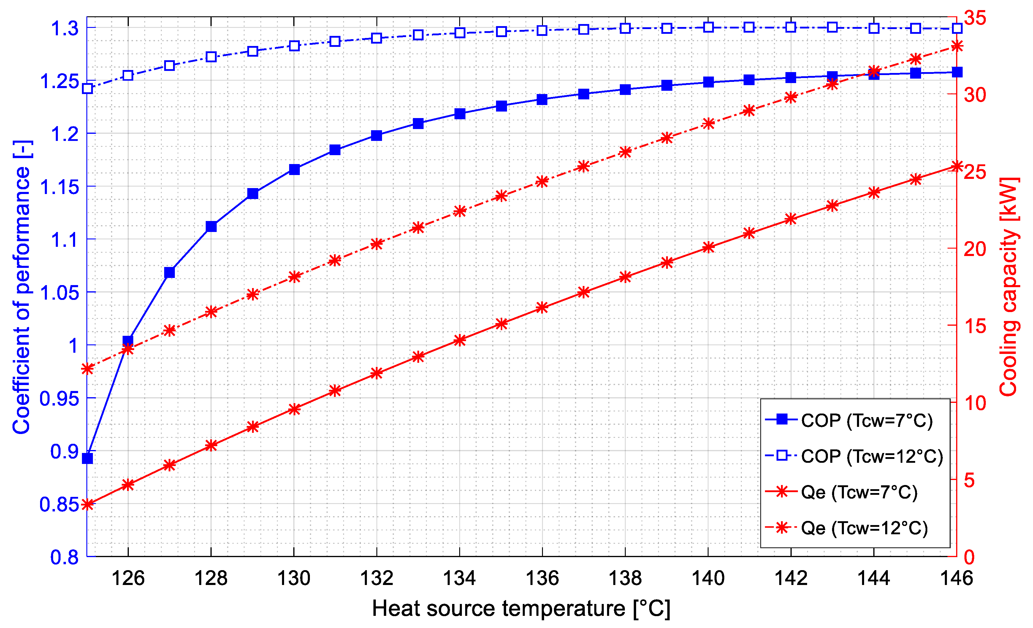
Figure 15 and Figure 16 show the variation of the coefficient of performance and cooling capacity versus the heat-source temperature for both the single and double-effect absorption-cooling cycles operating in these three climate zones. Chilled-water temperatures were 7 °C and 12 °C. The geometric and operational parameters of the underground heat-exchanger were set in such a way as to supply cooling water to the absorber and condenser at 33 °C. This value, which was recommended by several published investigations [2,41,42], meant that the underground tube did not need to be excessively long.
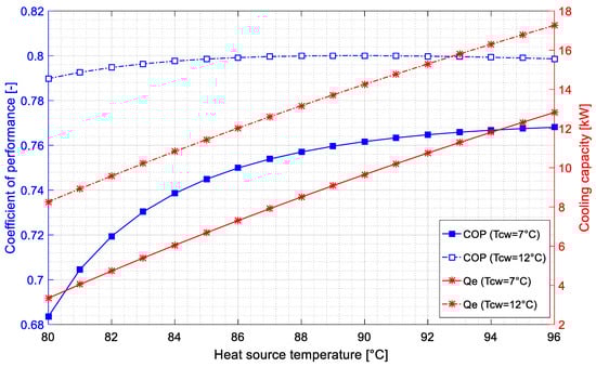
Figure 15.
Coefficient of performance and cooling-capacity versus the heat-source temperature of the single-effect absorption-cooling cycle, using a geothermal heat-sink in climate zones D, E, and F.
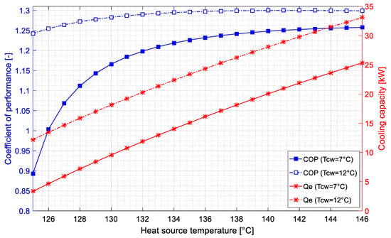
Figure 16.
Coefficient of performance and cooling-capacity versus the heat-source temperature of the double-effect absorption-cooling cycle, using a geothermal heat-sink in climate zones D, E, and F.
A significant improvement was obtained in the coefficient of performance of the single-effect absorption cycle at chilled-water temperatures of 7 °C and 12 °C, regardless of the climate zones. Maximum values of 0.76 and 0.79 were obtained at heat-source temperatures of 94 °C and 90 °C, respectively, as shown in Figure 15. The cooling capacity of the single-effect absorption cycle was approximately 85% of the nominal value at chilled-water temperatures of 7 °C. By increasing the chilled-water temperature to 12 °C, the cooling capacity was 7% higher than the nominal value.
As regards the double-effect absorption-cooling cycle (Figure 16), the maximum COP values, at 7 °C and 12 °C of chilled water temperature, are 1.25 and 1.29 at heat-source temperatures of 143 °C and 135 °C, respectively (Figure 16). The double-effect absorption cycle was able to operate at full nominal-cooling-capacity at a 7 °C chilled-water temperature, and 10% over its nominal-cooling-capacity at a chilled-water temperature of 12 °C.
In comparison with the results shown in Figure 5, Figure 6, Figure 7 and Figure 8, where both absorption-cooling cycles were unable to operate in the hot climate conditions of zones D, E and F, the use of the ground as a heat-sink allowed both absorption cycles to operate with a coefficient of performance and cooling-capacity near the nominal values. In addition, low temperatures were required for the heat source.
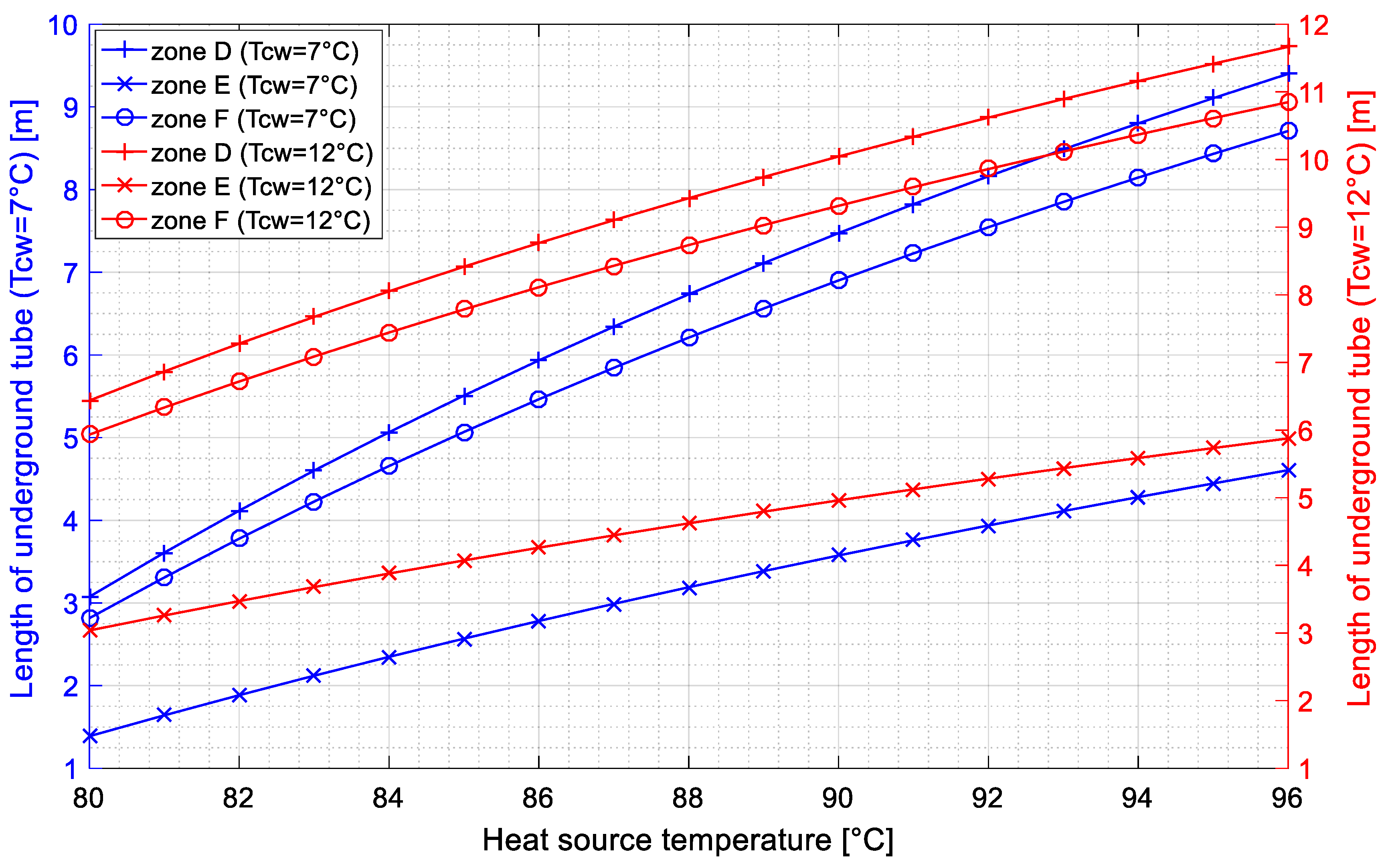
The variation of the underground-tube length versus the heat-source temperature for the single-effect absorption-cooling cycle for climate zones D, E and F is represented in Figure 17. Chilled-water temperatures were set at 7 °C and 12 °C. From this figure, it is apparent that climate zone E, which presents the highest ambient temperatures, requires approximately 50% the tube length required by zones D and F. This could be explained by the soil temperature at 2 m of depth, which is 22 °C, while the temperatures corresponding to zones D and F are 28 °C and 27 °C, respectively. The tube length was extended by approximately 25% for a chilled-water temperature of 12 °C. This could be explained by the higher amount of heat rejected from the absorber and condenser.
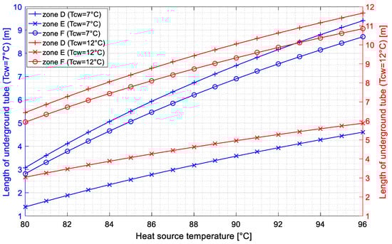
Figure 17.
Underground-tube length required for the single-effect absorption-cooling cycle in climate conditions in zones D, E and F.
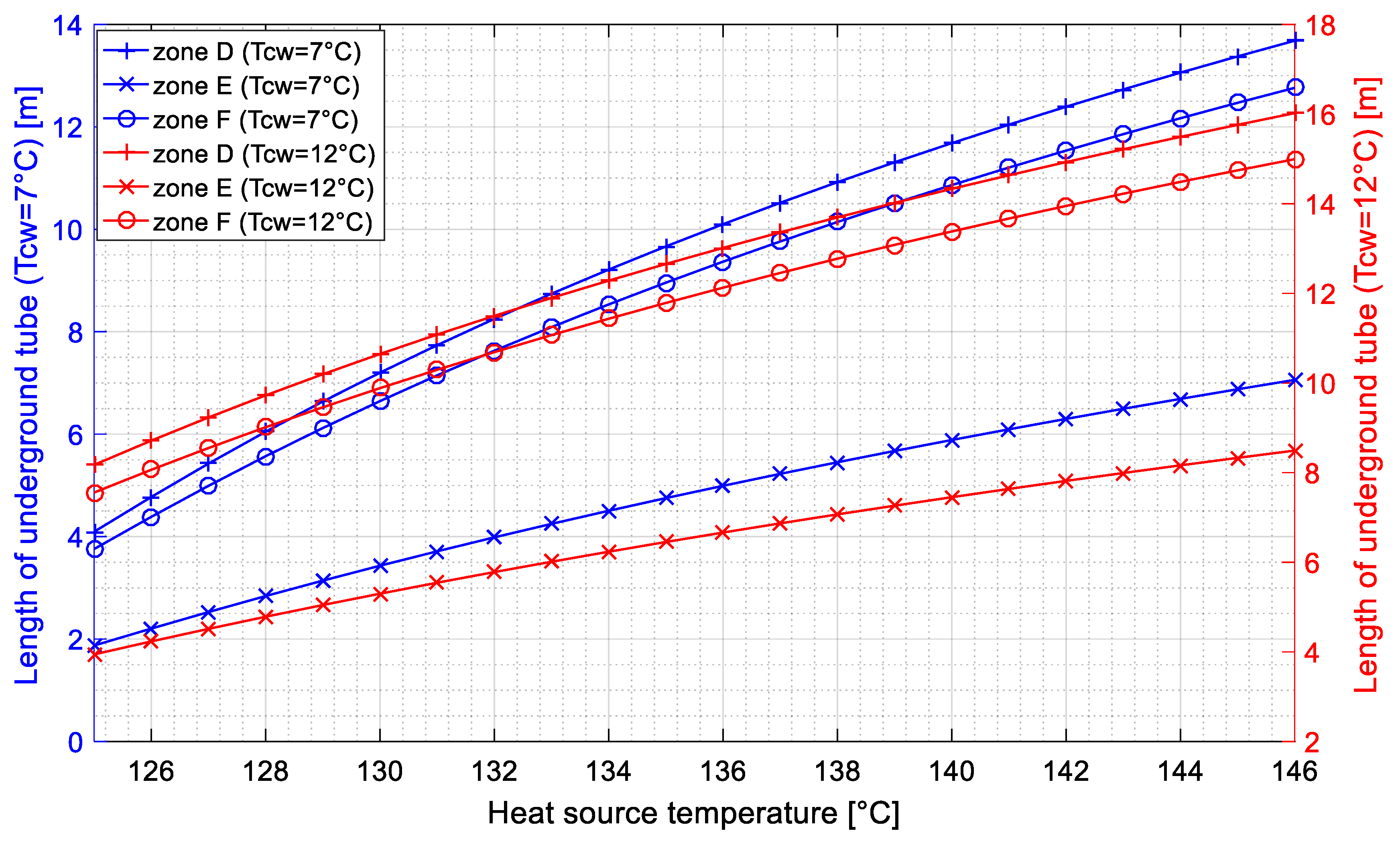
Figure 18 shows the underground-tube length versus the heat-source temperature for the double-effect absorption-cooling cycle for climate zones D, E, and F. Chilled-water temperatures were again set at 7 °C and 12 °C. It is worthy of note that the length required for the underground tube was approximately 35% more than that required for the single-effect absorption-cooling cycle. This is mainly due to the higher amount of heat rejected in the double-effect absorption cycle powered by high-temperature heat sources.
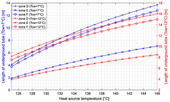
Figure 18.
Underground-tube length required for the double-effect absorption-cooling cycle in the climate conditions in zones D, E and F.
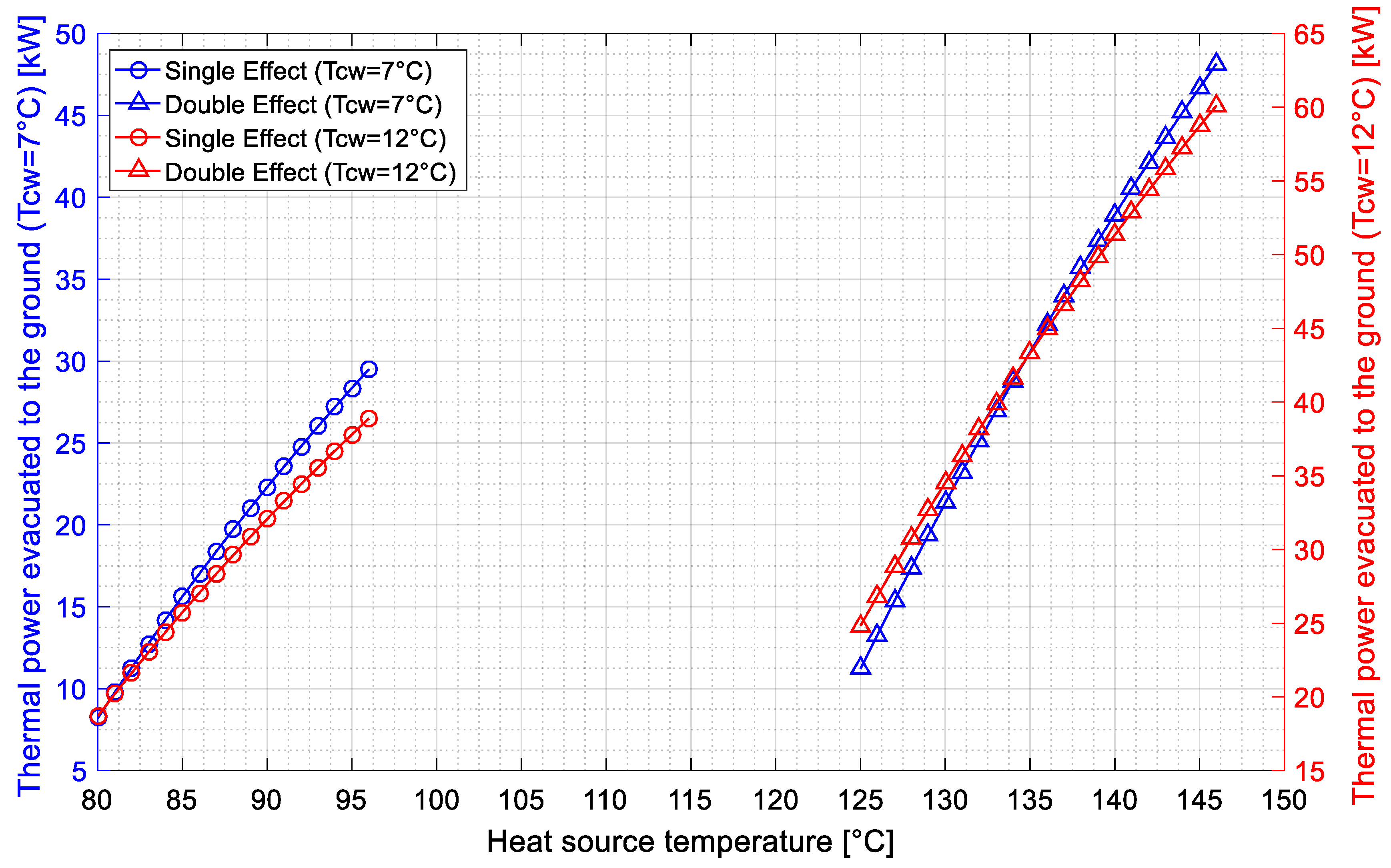
Rejected heat versus the heat-source temperature is presented in Figure 19 for both single and double-effect absorption-cooling cycles at chilled-water temperatures of 7 °C and 12 °C. It is worthy of note that the higher the heat-source temperature, the greater the amount of heat dissipated into the ground by the underground tube. Moreover, increasing the chilled-water temperature to 12 °C increases the amount of heat dissipated into the ground by 33% in the case of the single-effect absorption cycle, and by 30% in the case of the double-effect absorption cycle.
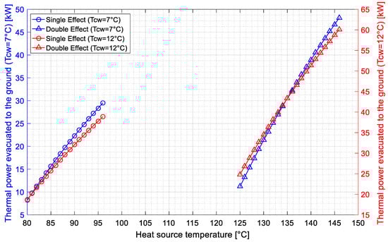
Figure 19.
Heat dissipated into the ground versus the heat-source temperature for the single- and double-effect absorption-cooling cycles.
4. Conclusions
This paper investigated the use of a geothermal heat-sink to remove the heat released in small-capacity single and double-effect water–LiBr absorption chillers in hot climates. A case study of the Algerian Sahara region was considered. A classification of the Algerian climate consisted of eight zones, of which three were Sahara Desert regions characterized by severe ambient temperatures, namely zones D, E and F.
A performance analysis of the single- and double-effect absorption-cooling cycles was carried out in the eight climate zones, taking into consideration the effect of maximum ambient temperature. This meant that areas where the two absorption cycles were less efficient or unable to operate could be identified. In a second step, the nature of the soil in those areas was investigated, and the depth from which soil temperature remained constant was determined. A parametric study was then performed, to characterize the underground heat-exchanger used to dissipate heat released by the absorption cycles into the ground. This heat-exchanger was designed to supply cooling water at an inlet temperature of 33 °C in hot climate conditions, where ambient temperatures vary from 38 °C to 42 °C. In the final part, the performance of the absorption-cooling cycles coupled with an underground heat-exchanger was analyzed. The most significant results are summarized below:
- Both single- and double-effect absorption-cooling cycles were unable to operate efficiently or even unable to operate at all in the climate conditions of the Saharan zones D, E and F.
- When the single-effect absorption cycle was connected to a geothermal heat-sink in zones D, E and F, maximum COP values of 0.76 and 0.79 were obtained at heat-source temperatures of 94 °C and 90 °C, respectively. The cooling capacity was approximately 85% of the nominal value at a chilled-water temperature of 7 °C, and 7% over the nominal value at a chilled-water temperature of 12 °C.
- As regards the double-effect absorption cycle, the maximum COP values were 1.25 and 1.29 at chilled-water temperatures of 7 °C and 12 °C and heat-source temperatures of 143 °C and 135 °C, respectively. The double-effect absorption-cycle was able to operate at full nominal-cooling-capacity at a 7 °C chilled-water temperature, and 10% over its nominal cooling capacity at a chilled-water temperature of 12 °C.
- The underground-tube length required in the heat-sink depended on the climate zone for both the single- and double-effect absorption-cooling cycles. As regards the single-effect absorption cycle, climate zone E, which presented the highest ambient temperatures, required approximately 50% of the tube length needed by zones D and F. This could be explained by the soil temperature at 2 m depth, which is 22 °C, while the temperatures corresponding to zones D and F are 28 °C and 27 °C, respectively. The tube length was approximately 25% longer when the chilled-water temperature was set at 12 °C. This could be explained by the higher amount of heat dissipated in the absorber and condenser. In the case of the double-effect absorption cycle, the length required for the underground tube was approximately 35% more than that required for the single-effect absorption cycle.
Author Contributions
Conceptualization, formal analysis, investigation, methodology, O.K. and M.B.; software, validation, writing—original draft, O.K., H.A. and B.L.; writing—review and editing, supervision, O.K. and M.B. All authors have read and agreed to the published version of the manuscript.
Funding
This research received no external funding.
Data Availability Statement
The data presented in this study are available upon request from the corresponding author.
Conflicts of Interest
The authors declare no conflict of interest.
Nomenclature
| Cp | Specific heat | kJ/kg·K |
| D | Diameter/Depth | m |
| h | Specific enthalpy/Convective heat transfer coefficient, | kJ/kg—W/m²·K |
| L | Length | m |
| M | Molar mass | mol |
| ṁ | Mass flow rate | kg/s |
| P | Circumference | m |
| Heat duty | W | |
| S | Surface | m² |
| T | Temperature | °C |
| t | Time | s |
| w | Molar concentration | mol/l |
| W | Work | J |
| X | Concentration of LiBr | kgLiBr/kgsol |
| Greek letters | ||
| α | Diffusivity | m²/s |
| ρ | Density | kg/m3 |
| λ | Thermal conductivity | W/m·K |
| Subscripts | ||
| LiBr | Lithium Bromide | |
| H2O | Water | |
| COP | Coefficient of performance | |
| cw | Chilled-water | |
| e | Evaporator | |
| g | Generator/Ground | |
| i | Inlet | |
| o | Outlet |
References
- Ministère Algérien de l’Energie. Bilan Energétique National 2019. 2020. Available online: https://www.energy.gov.dz/ (accessed on 1 March 2022).
- Ketfi, O.; Merzouk, M.; Merzouk, N.K.; Bourouis, M. Feasibility study and performance evaluation of low-capacity water-LiBr absorption cooling systems functioning in different Algerian climate zones. Int. J. Refrig. 2017, 82, 36–50. [Google Scholar] [CrossRef]
- Agrouaz, Y.; Bouhal, T.; Allouhi, A.; Kousksou, T.; Jamil, A.; Zeraouli, Y. Energy and parametric analysis of solar absorption cooling systems in various Moroccan climates. Case Stud. Therm. Eng. 2017, 9, 28–39. [Google Scholar] [CrossRef]
- Merabti, L.; Merzouk, M.; Merzouk, N.K.; Taane, W. Performance study of solar driven solid desiccant cooling system under Algerian coastal climate. Int. J. Hydrog. Energy 2017, 42, 28997–29005. [Google Scholar] [CrossRef]
- Mortadi, M.; El Fadar, A. Performance, economic and environmental assessment of solar cooling systems under various climates. Energy Convers. Manag. 2022, 252, 114993. [Google Scholar] [CrossRef]
- Lu, D.; Liu, Z.; Bai, Y.; Cheng, R.; Gong, M. Study on the multi-energy complementary absorption system applied for combined cooling and heating in cold winter and hot summer areas. Appl. Energy 2022, 312, 118746. [Google Scholar] [CrossRef]
- Camara, S.; Sulin, A. Study of a double-acting solar collector for use in the absorption cooling system in hot regions. Therm. Sci. Eng. Prog. 2022, 31, 101286. [Google Scholar] [CrossRef]
- Kumar, G.; Ayou, D.; Narendran, C.; Saravanan, R.; Maiya, M.; Coronas, A. Renewable heat powered polygeneration system based on an advanced absorption cycle for rural communities. Energy 2023, 262, 125300. [Google Scholar] [CrossRef]
- Ghodbane, M.; Said, Z.; Ketfi, O.; Boumeddane, B.; Hoang, A.; Sheikholeslami, M.; El Haj Assad, M.; Ahmadi, M.H.; Nguyen, V.; Tran, V.D.; et al. Thermal performance assessment of an ejector air-conditioning system with parabolic trough collector using R718 as a refrigerant: A case study in Algerian desert region. Sustain. Energy Technol. Assess. 2022, 53, 102513. [Google Scholar] [CrossRef]
- Allouhi, A. Techno-economic and environmental accounting analyses of an innovative power-to-heat concept based on solar PV systems and a geothermal heat pump. Renew. Energy 2022, 191, 649–661. [Google Scholar] [CrossRef]
- Beckers, K.; Rangel-Jurado, N.; Chandrasekar, H.; Hawkins, A.; Fulton, P.; Tester, J. Techno-Economic Performance of Closed-Loop Geothermal Systems for Heat Production and Electricity Generation. Geothermics 2022, 100, 102318. [Google Scholar] [CrossRef]
- Baba, A.; Sözbilir, H.; Sayık, T.; Arslan, S.; Uzelli, T.; Tonkul, S.; Demir, M. Hydrogeology and hydrogeochemistry of the geothermal systems and its direct use application: Balçova-Narlıdere geothermal system, Izmir, Turkey. Geothermics 2022, 104, 102461. [Google Scholar] [CrossRef]
- Haris, M.; Hou, M.; Feng, W.; Mehmood, F.; Saleem, A. A regenerative Enhanced Geothermal System for heat and electricity production as well as energy storage. Renew. Energy 2022, 197, 342–358. [Google Scholar] [CrossRef]
- Kabeyi, M.B.; Olanrewaju, O.A. Geothermal wellhead technology power plants in grid electricity generation: A review. Energy Strategy Rev. 2022, 39, 100735. [Google Scholar] [CrossRef]
- Deng, J.; Ma, M.; Wei, Q.; Liu, J.; Zhang, H.; Li, M. A specially-designed test platform and method to study the operation performance of medium-depth geothermal heat pump systems (MD-GHPs) in newly-constructed project. Energy Build. 2022, 272, 112369. [Google Scholar] [CrossRef]
- Zeng, C.; Yuan, Y.; Haghighat, F.; Panchabikesan, K.; Cao, X.; Yang, L.; Leng, Z. Thermo-economic analysis of geothermal heat pump system integrated with multi-modular water-phase change material tanks for underground space cooling applications. J. Energy Storage 2022, 45, 103726. [Google Scholar] [CrossRef]
- Cui, Y.; Zhu, J.; Twaha, S.; Chu, J.; Bai, H.; Huang, K.; Chen, X.; Zoras, S.; Soleimani, Z. Techno-economic assessment of the horizontal geothermal heat pump systems: A comprehensive review. Energy Convers. Manag. 2019, 191, 208–236. [Google Scholar] [CrossRef]
- Self, S.; Reddy, B.; Rosen, M. Geothermal heat pump systems: Status review and comparison with other heating options. Appl. Energy 2013, 101, 341–348. [Google Scholar] [CrossRef]
- Blázquez, C.S.; Nieto, I.M.; González, M.M.; García, P.C.; Martín, A.F.; González-Aguilera, D. Geophysical exploration for shallow geothermal applications: A case study in Artà, (Balearic Islands, Spain). Geothermics 2022, 105, 102517. [Google Scholar] [CrossRef]
- Lebbihiat, N.; Atia, A.; Arıcı, M.; Meneceur, N. Geothermal energy use in Algeria: A review on the current status compared to the worldwide, utilization opportunities and countermeasures. J. Clean. Prod. 2021, 302, 126950. [Google Scholar] [CrossRef]
- Benzaamaa, M.; Menhoudj, S.; Kontoleon, K.; Mokhtari, A.; Lekhal, M. Investigation of the thermal behavior of a combined geothermal system for cooling with regards to Algeria’s climate. Sustain. Cities Soc. 2018, 43, 121–133. [Google Scholar] [CrossRef]
- Hebbal, B.; Marif, Y.; Hamdani, M.; Belhadj, M.M.; Bouguettaia, H.; Bechki, D. The geothermal potential of underground buildings in hot climates: Case of Southern Algeria. Case Stud. Therm. Eng. 2021, 28, 101422. [Google Scholar] [CrossRef]
- Bassoud, A.; Khelafi, H.; Mokhtari, A.M.; Bada, A. Evaluation of summer thermal comfort in arid desert areas. Case study: Old adobe building in Adrar (South of Algeria). Build. Environ. 2021, 205, 108140. [Google Scholar] [CrossRef]
- Aryal, M.R.; Pun, S.; Yadav, A.; Basnet, B. Study, Design, and Analysis of Geothermal Cooling System and Its Possibilities in the Terai Region of Nepal. J. Inst. Eng. (India) Ser. C 2021, 102, 777–787. [Google Scholar] [CrossRef]
- Kalantar, V.; Khayyaminejad, A. Numerical simulation of a combination of a new solar ventilator and geothermal heat exchanger for natural ventilation and space cooling. Int. J. Energy Environ. Eng. 2021, 13, 785–804. [Google Scholar] [CrossRef]
- Shah, M.; Kathiriya, H.; Kakadiya, M.; Boghara, V.; Sircar, A.; Thakore, S. Model design of condenser for solar assisted geothermal cooling system using software simulation. Model. Earth Syst. Environ. 2019, 5, 33–40. [Google Scholar] [CrossRef]
- Pàtek, J.; Klomfar, J. A computationally effective formulation of the thermodynamic properties of Libr-H2O solutions from 273 to 500K over full composition range. Int. J. Refrig. 2006, 29, 566–578. [Google Scholar] [CrossRef]
- Van Reenen, D. Modelling the Performance of Underground Heat Exchangers and Storage Systems. Master Thesis, Chalmers University of Technology, Göteborg, Sweden, 2011. [Google Scholar]
- Kusuda, T. The effect of ground cover on earth temperature. In Proceedings of the Conference on Alternatives in Energy Conservation: The Use of Earth-covered Buildings, Fort Worth, Texas, July 9–12; U.S. Government Publishing Office: Washington, DC, USA, 1975; pp. 279–303. [Google Scholar]
- Geothermal cooling, Caractéristiques thermiques des sols. Available online: https://energieplus-lesite.be/ (accessed on 1 December 2021).
- CNERIB, Ministère Algérien de l’Habitat. CNERIB Classification, Recommandations architecturales. Editions ENAG, Alger.; 2011. Available online: http://www.mhuv.gov.dz (accessed on 1 March 2022).
- Maryami, R.; Dehghan, A. An exergy based comparative study between LiBr/water absorption refrigeration systems from half effect to triple effect. Appl. Therm. Eng. 2017, 124, 103–123. [Google Scholar] [CrossRef]
- Rodríguez-Toscano, A.; Amaris, C.; Sagastume-Gutierrez, A.; Bourouis, M. Technical, environmental, and economic evaluation of a solar/gas driven absorption chiller for shopping malls in the Caribbean region of Colombia. Case Stud. Therm. Eng. 2022, 30, 101743. [Google Scholar] [CrossRef]
- Sharifi, S.; Heravi, F.N.; Shirmohammadi, R.; Ghasempour, R.; Petrakopoulou, F.; Romeo, L. Comprehensive thermodynamic and operational optimization of a solar-assisted LiBr/water absorption refrigeration system. Energy Rep. 2020, 6, 2309–2323. [Google Scholar] [CrossRef]
- Jain, V.; Singhal, A.; Sachdeva, G.; Kachhwaha, S. Advanced exergy analysis and risk estimation of novel NH3-H2O and H2O-LiBr integrated vapour absorption refrigeration system. Energy Convers. Manag. 2020, 224, 113348. [Google Scholar] [CrossRef]
- Hong, S.J.; Bae, K.J.; Nguyen, T.; Kim, H.G.; Kim, I.; Kim, N.Y.; Kwon, O.K.; Park, C.W. Development of thermally-driven hybrid Water-LiBr absorption system for simultaneously supplying steam and refrigeration effect. Appl. Therm. Eng. 2022, 201, 117792. [Google Scholar] [CrossRef]
- Alsagri, A.S.; Chiasson, A.; Shahzad, M.W. Geothermal Energy Technologies for Cooling and Refrigeration Systems: An Overview. Arab. J. Sci. Eng. 2021, 47, 7859–7889. [Google Scholar] [CrossRef]
- Ministère Algérien des Resources en Eau. Technical Report; Document Interne; ANRH: Alger, Algeria, 2014. [Google Scholar]
- Chabour, N.; Mebrouk, N.; Hassani, M.; Upton, K.; Dochartaigh, B.; Bellwood-Howard, I. Atlas de l’eau souterraine en Afrique: Hydrogéologie de l’Algérie. British Geological Survey. Available online: http://earthwise.bgs.ac.uk/index.php/Hydrogéologie_d’Algérie (accessed on 1 December 2021).
- Benhammou, M.; Draoui, B. Modélisation de la température en profondeur du sol pour la région d’Adrar-Effet de la nature du sol. Revue des Energies Renouvelables—CDER. J. Renew. Energ. 2011, 14, 219–228. [Google Scholar]
- Xiaoyong, C. BCT16 Commissioning Instruction and Explanation Notes; Broad, Co.: Changsha, China, 2004. [Google Scholar]
- Yazaki Corporation. WFC-SC5 chiller, specifications. 2008. Available online: www.yazakienergy.com (accessed on 1 March 2022).


Disclaimer/Publisher’s Note: The statements, opinions and data contained in all publications are solely those of the individual author(s) and contributor(s) and not of MDPI and/or the editor(s). MDPI and/or the editor(s) disclaim responsibility for any injury to people or property resulting from any ideas, methods, instructions or products referred to in the content. |
© 2023 by the authors. Licensee MDPI, Basel, Switzerland. This article is an open access article distributed under the terms and conditions of the Creative Commons Attribution (CC BY) license (https://creativecommons.org/licenses/by/4.0/).