Article

Reservoir Characterization and an Integrated Approach of Reservoir Modeling for Miano Gas Field, Middle Indus Basin

1
BGP Inc., China National Petroleum Cooperation, Zhuozhou 072750, China
2
Research Institute of Petroleum Exploration and Development, China National Petroleum Cooperation, Beijing 100083, China
3
College of Petroleum Engineering, China University of Petroleum (East China), Qingdao 266000, China
4
China National Petroleum Corporation Tarim Oilfield Company, Korla 841000, China
5
College of Petroleum Engineering, China University of Petroleum (Beijing), Beijing 102249, China
*
Authors to whom correspondence should be addressed.
Energies 2023, 16(2), 856; https://doi.org/10.3390/en16020856
Submission received: 24 November 2022 / Revised: 3 January 2023 / Accepted: 7 January 2023 / Published: 11 January 2023

Abstract

:
The hydrocarbon-bearing formation of Miano gas field belongs to the Early Cretaceous and it is bounded by two shale intervals, which are considered as maximum flooding surfaces (MFS). The hydrocarbon-bearing interval includes two reservoir units: a tight gas reservoir and its overlying conventional reservoir. Core samples, borehole logs, and well production performance revealed that the two reservoirs present reversed trends in reservoir quality through the gas field without obvious barriers. The average shale volume of the tight gas reservoir changes from 24.3% to 12.2% and the average permeability changes from 32.65 mD to 0.02 mD from the south to north. However, the average effective porosity of the overlaying conventional reservoir increases from 20% to 26% and the average permeability increases from 10 mD to 300 mD. The reversed trends in the two reservoirs lead to challenges in production forecast and development well proposals in the tight gas reservoir. Therefore, reservoir characterization and a predictive reservoir model are essential for further exploitation of Miano gas field. The geological genesis analysis integrating cores, borehole logs, and three-dimensional (3D) seismic data reveals that the producing interval of the tight gas reservoir is tidal-influenced shore facies deposition with intergranular pore space reduced by mineral cementation during burial diagenesis, while the overlaying conventional reservoir is fluvial-influenced deltaic deposition with abundant, well-connected intergranular macropores, which leads to a better reservoir quality. A reservoir model containing both the tight gas reservoir and the conventional reservoir is constructed considering the reservoir nature understanding, and the accuracy of the model is confirmed by reservoir surveillance activities with the simulation model. The study will be critical to the further reservoir development and hydrocarbon production in Miano gas field.

1. Introduction

Reservoir characterization and modeling are considered effective methods to increase precision in reservoir prediction and to reduce subsurface uncertainty in reservoir exploitation [1,2]. Reservoir heterogeneities can be captured through accurate reservoir characterization integrating multiple types of data, including cores, borehole logs, seismic volumes, and production performances, with different scales and resolutions. Reservoir modeling realizes reservoir architectures and characters using stochastic and determined methods in three-dimensional (3D) space. It becomes a foundation of techniques for reserve recovery improvement [2,3].
Abundant approaches of reservoir characterization and modeling were applied to hydrocarbon-bearing formations in Indus basin to describe reservoirs and to reduce surface uncertainties. In previous research, the approaches for conventional reservoirs include two routine techniques: 1. petrophysical analysis for lithology and fluid discrimination [4,5,6,7] and 2. subsurface modeling driven by geophysical data, including seismic attributes and stochastic inversions [6,7,8,9]. Additional aspects, including geomechanics, geochemistry, and fracture networks, are often considered for tight reservoir characterization and modeling [10,11]. In spite of the tremendous efforts and methods, challenges in reservoir characterization and modeling in Indus Basin still exist because of the heavy heterogeneities caused by rapid lithology variations in the hydrocarbon-bearing formations. The heavy heterogeneities lead to different reservoir quality distribution in vertical or lateral directions and the unknown geological nature of these reservoirs brings difficulties in reservoir characterization and modeling.
Miano gas field is located in the southwest of middle Indus Basin, with a total area of 814.02 sq. km (Figure 1) [12]. The first well drilled in the field was Miano-1 well in 1993. The well reached a total depth of 4030 in the Sember formation [9,13]. Totally, 34 wells were drilled at the end of 2020. Among the wells, 11 wells have completed well log series [14], and core samples were acquired from 18 wells. The 3D seismic data were acquired in 1999 [12,15] and reprocessed in 2020.
The hydrocarbon-bearing interval in the Miano gas field only developed in the Lower Goru Formation, Early Cretaceous [9]. The hydrocarbon-bearing interval contains two reservoirs: a tight gas reservoir and its overlying conventional gas reservoir. The two reservoirs were considered independent in early stages of the field development because of very different reservoir qualities and thickness in the vertical direction [9]. The conventional gas reservoir exists in the upper part of the B interval. Well tops revealed that the thickness of the reservoir ranges from 10 to 20 m. Core samples and well logs indicated that the average porosity of the reservoir is about 25% and the average permeability is about 10 mD. A tight gas reservoir is overlain by the conventional reservoir. Well tops revealed that the total thickness of the tight reservoir ranges from 50 to 100 m but the thickness of the current producing interval in the reservoir is only approximately 15 to 20 m. Core samples and well logs indicated that the average porosity of H reservoir is about 10% and the permeability of the reservoir is less than 1 mD. The tight gas reservoir and the overlying conventional gas reservoir also present inverse depositional trends in the horizontal direction, proved by borehole logs and well production performances.
However, the absence of an observed barrier between the two reservoir units makes the independent development of the two reservoir units incredible. A single pressure gradient also indicates that the two reservoir units may not be isolated and the nature of the horizontal inverse depositional trends in the two reservoir units is unclear based on the understanding in the earlier development stages. The coexistence of the two reservoir units brings difficulties for production forecast and development well proposals for the two reservoir units because of unknown reservoir quality contributions in each reservoir. The coexistence of these two reservoir units also cannot be ignored and should be integrated in reservoir characterization and modeling for the whole hydrocarbon-bearing interval.
In this study, a geological genesis analysis is applied to the reservoir development in Miano gas field using data of cores, borehole logs, full-bore micro-scan imager (FMI) logs, and seismic data. The analysis intends to reveal the geological origins, having implications to the reversed trend in reservoir quality of the two reservoirs, in aspects of sequence, deposition, and postdeposition diagenesis. The distribution of reservoirs and petrophysical features are also included in the analysis. Then, a static reservoir model is built following the geological genesis analysis. The model presents obvious geologic features that are in accordance with the understanding of the geological nature of the reservoir. The hydraulic fractures were also compiled into the model. The reliability of the reservoir model is confirmed by the wells and reservoir performance.

2. Geological Settings

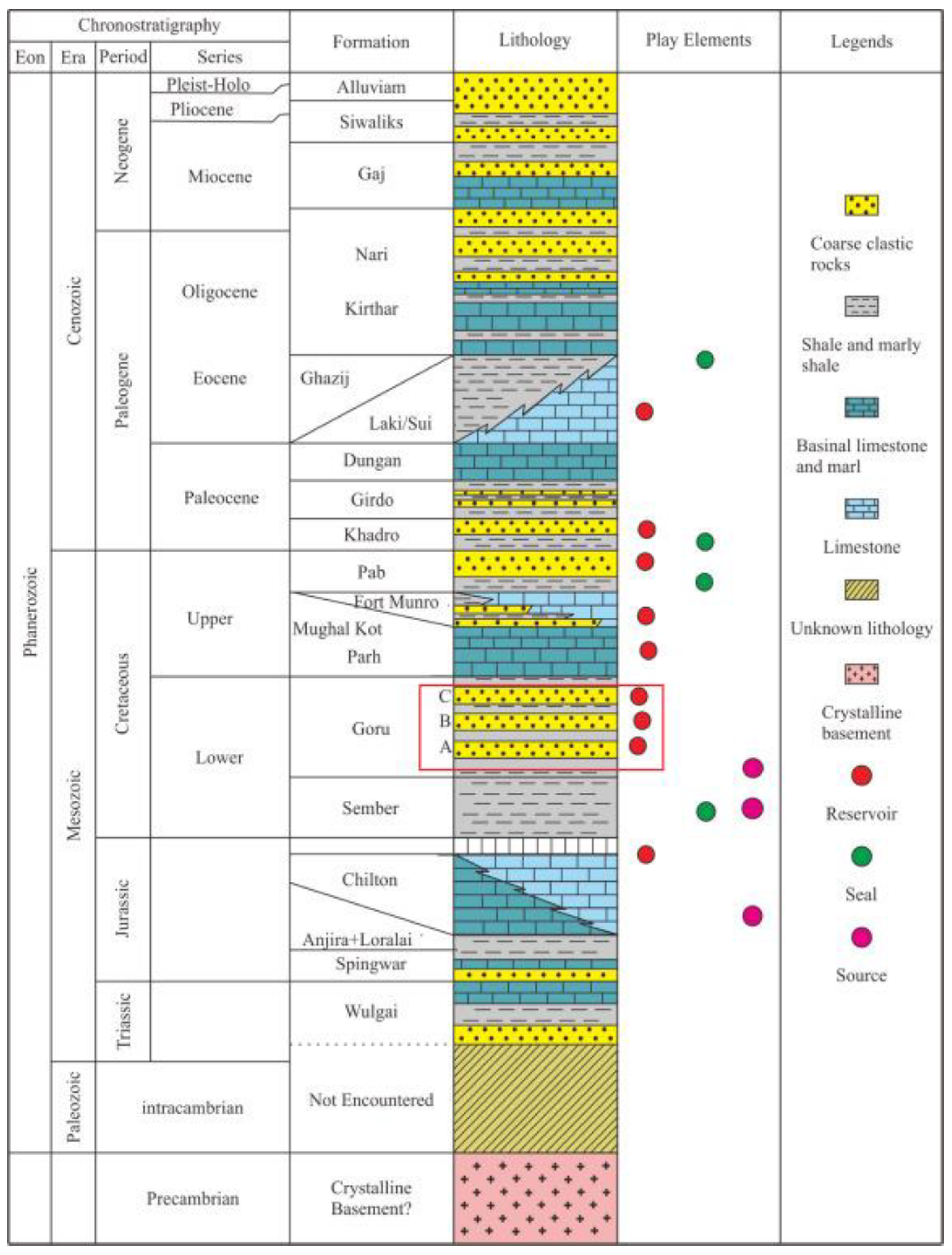
The Great Indus Basin initiated in the Precambrian. Contemporary structural features of the basin are a result of multiple evolution stages related to plate rifting and collision [16,17]. The Greater Indus Basin includes three sub-basins, known as upper Indus Basin, middle Indus Basin, and lower Indus Basin [17,18]. Middle Indus Basin, which is gas-prolific, is bounded by the Indian shield in the east; Kirthar Ranges, Sulaiman Fold, and Thrust Belt in the west; Sargodha High in the north; and Jacobabad–Khairpur High in the south [17]. Multiple formations deposited in the middle Indus Basin from the Permian to the Neogene. Among these formations, a complete petroleum system developed in the Cretaceous. Marine shale in Sembar Formation at the bottom of the Lower Cretaceous is the main hydrocarbon source rock, which is about 600–800 m thick [4]. The overlying Goru Formation is divided into two intervals. Shale dominating the Upper Goru Formation is considered as a regional sealing [4,17]. Shore to neritic facies depositions composited by sandstone, siltstone, inter-bedded shale, and thin limestone developed in the Lower Goru Formation [19,20]. Three stratigraphic intervals, named as A, B, and C, are divided in the Lower Goru Formation (Figure 2) [5].

3. Methodology

The tight and the conventional reservoir units both developed in the hydrocarbon-bearing interval of Miano gas field. The different depositional backgrounds of the two reservoirs brought high heterogeneities in both vertical and horizontal directions. The heterogeneities cannot be neglected in reservoir modeling and the following numerical simulation. Therefore, there is no predictivity in reservoir characterization and modeling without an understanding on the origins of the two reservoirs. Therefore, an integrated method aiming at the heavy heterogeneity is adopted to make predictive reservoir characterization and modeling. The method contains two major steps: geological genesis analysis for the reservoir and reservoir modeling guided by the analysis (Figure 3).
Geological genesis analysis has been proven an effective method to improve predictivity in reservoir characterization and modeling for different types of reservoirs [21,22,23,24]. In this study, the geological genesis analysis is applied to the reservoirs before reservoir modeling for the two reservoirs. Wells with complete series of conventional logs (GR, resistivity, acoustic logs, etc.), core data (core description, thin sections, and SEM), and FMI logs covering the two reservoirs are selected for the analysis. Shore and delta-front facies are identified in the two reservoirs, respectively, integrating direct proofs in core data and curve features of well logs. Then, a sequence framework is formed using a high-resolution sequence stratigraphy theory [25,26]. The whole hydrocarbon-bearing interval is divided into five geologic units based on the framework. Then, the depositional process of Unit 4 and 5, which contains the tight gas reservoir and the conventional reservoir, respectively, was restored, integrating proofs from stratigraphic isopach maps generated from seismic interpretation. Finally, a postdeposition diagenesis study using core thin section and SEM photos is conducted and its implication to reservoir quality is revealed. The geological analysis casts an interpretation for the origins of the two different reservoirs and the reversed trend depositional trends in the two reservoir units.
The reservoir model of the tight and the conventional reservoir units is built under the guidance of the geological genesis analysis. The structure framework of the model is built based on the geologic unit division and faults interpretation from seismic data. The 3D cellular system of the reservoir model is generated, honoring well tops, seismic interpretation results, and the model computation efficiency (total cell numbers). The reservoir property models, including shale volume (Vsh), porosity (φ), rock type (RT), and permeability (k), are propagated by facies-constrained stochastic algorithms to realize geologic characters recognized by the geological genesis analysis. A water saturation (Sw) model is calculated by saturation height function (SHF) [27] and a net-to-gross ratio (NTG) model is calculated by given cutoffs in porosity and Vsh from petrophysical interpretation results. The hydraulic fractures in the tight gas reservoir are also complied into the model. The reliability of the model is verified by history-matching performance of producers.

4. Geologic Genesis Analysis

4.1. Sequence Framework and Deposition

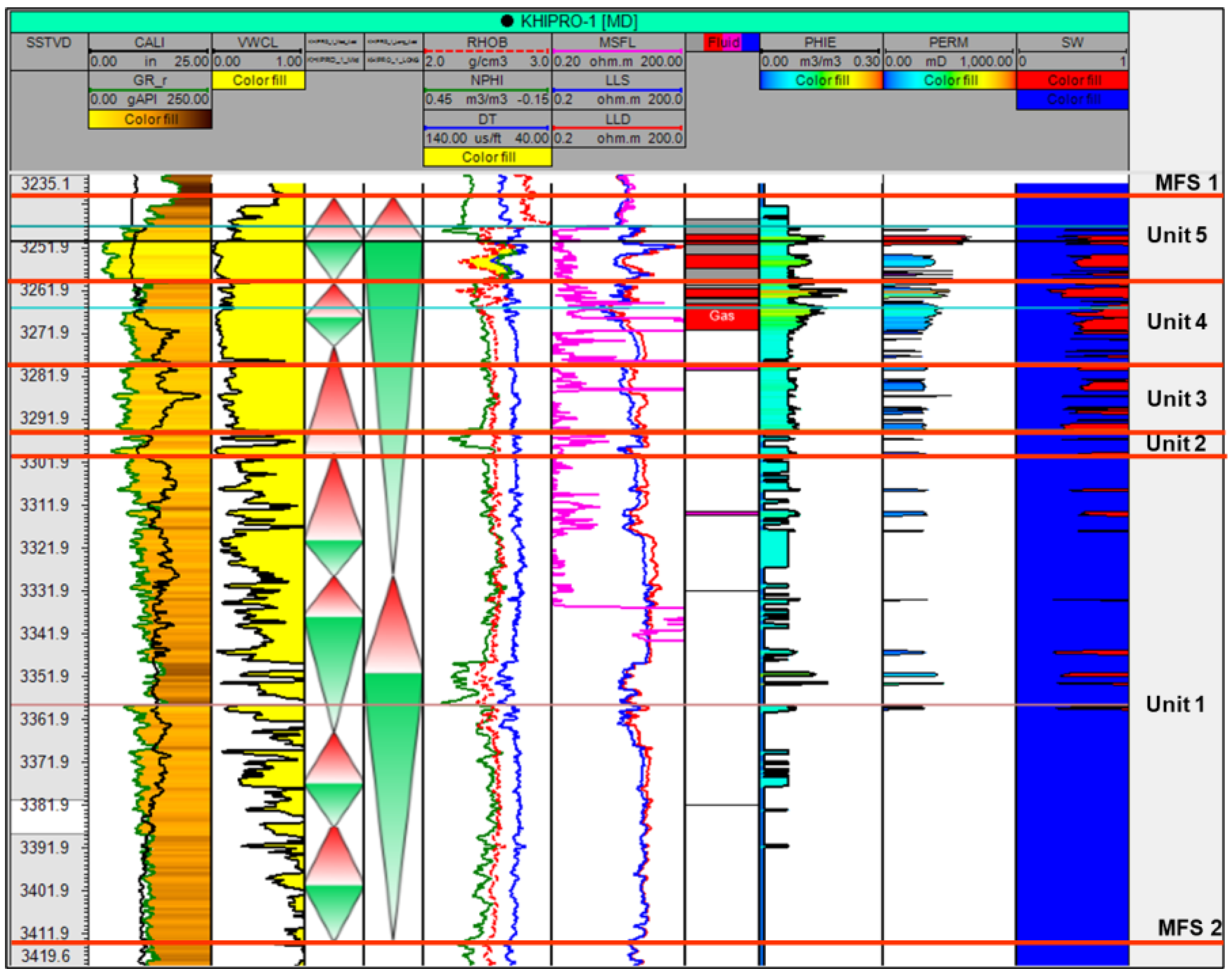
The aim of sequence framework is to define geologic units for the hydrocarbon-bearing formation in H field. The whole hydrocarbon-bearing formations is defined as a composite sequence bounded by two regional shale intervals as MSFs (MFS1 and MFS2), which are on the top and at the bottom of the hydrocarbon-bearing formation (Figure 4). The small layer thickness under the resolution of seismic data and rapid lithology changes in wells bring a difficulty in sequence division at a higher order [4,9]. Therefore, the high-resolution sequence stratigraphy theory considering base-level cycles [25,26] is applied to build the sequence framework. The composite sequence is divided into two middle-term sequences based on the observation from cores and the GR curve features. Then, the two middle-frequency cycles are furtherly divided into five to seven short-term sequences depending on core and FMI log observations, which are an effective tool in the recognition of short-term sequences [25,28]. Five geologic units are defined as Unit 1 to Unit 5 according to the base-level cycle divisions (Table 1). The tight reservoir unit is in Unit 4 and the overlying conventional reservoir is in the lower part of Unit 5.
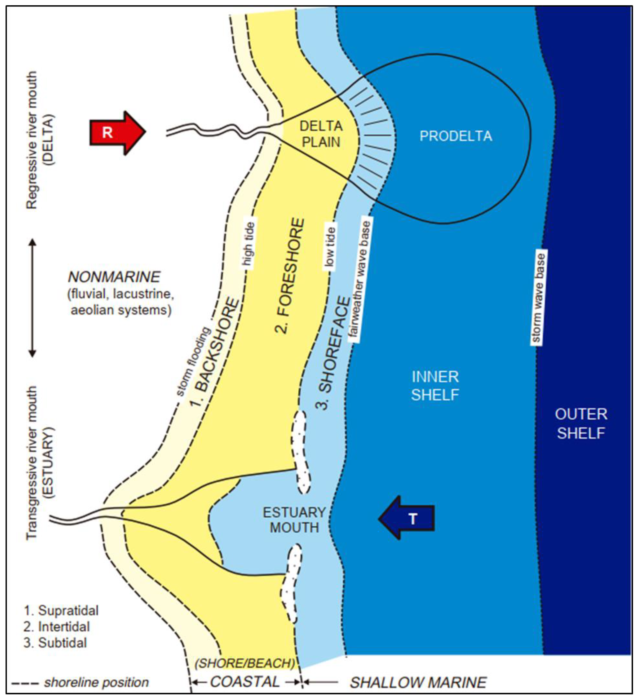
Deposition of the hydrocarbon-bearing formation is a response to sequences in Indus Basin [29]. Previous research proved that the hydrocarbon-bearing formation in H field is a shore to marginal marine facies in the regional scale [8,9,29,30]. However, base-level cycles bring different deposition features in each unit. Deltaic features developed in half cycles when the base-level descended, while tidal-influenced shore facies and storm deposition developed in half cycles when the base-level ascended. Figure 5 [31] illustrate a deposition scheme of the formation in H field.
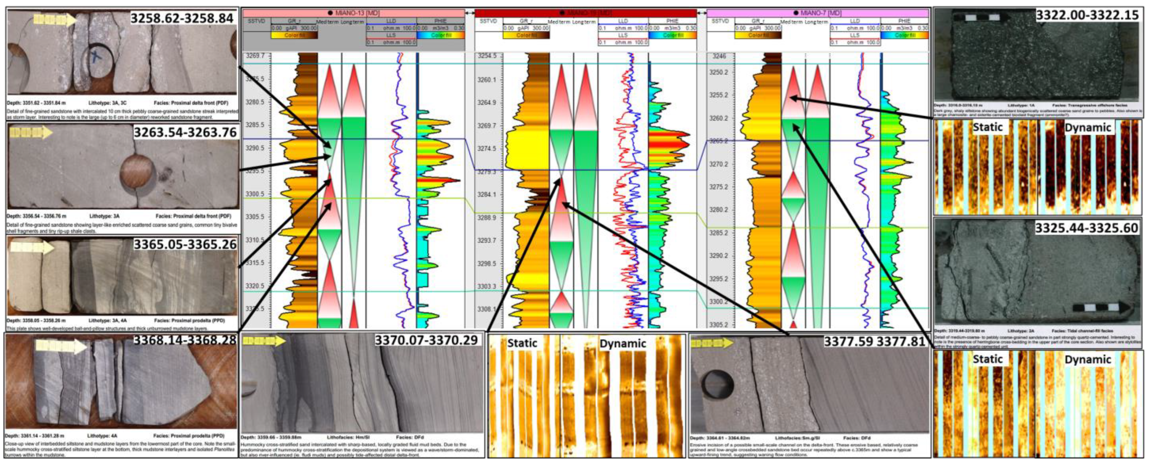
Unit 4, where the tight gas reservoir develops, locates at the early to middle period of a middle-term sequence. Core data reveal that the unit includes a nearly complete base-level cycle in short-term sequence. Siltstones with hummocky cross bedding and storm deposition at the bottom of the unit indicate the ascending half cycle, while fine sandstone with erosive surface, parallel bedding, and ball-pillow structure developed in the descending period (Figure 6). The unit presents a tidal-influenced shore facies. The GR curve in funnel shapes indicates existences of sand bars cut by tidal channels. Cores from different wells also prove that more severe local tidal erosion develops in the south of H field. The overlying Unit 5 contains the conventional gas reservoir. It is at a late descending to early ascending stage in the middle-term sequence. The unit contains a complete base-level cycle in the short-term sequence. The cycle was proved by variations in the lithologies and depositional structures. The lower part where the conventional reservoir develops is light grey, medium to fine sandstone with abundant crossing beddings. The FMI log also presents light, high-resistance features of sandstones. The GR log in a bell shape indicates developments of sand bars. The subzone is interpreted as fluvial-influenced delta front. Dark grey, shaly siltstones with burrows and bioturbations developing in the upper part of the unit indicate the ascending half cycle in the short-term sequence (Figure 6).
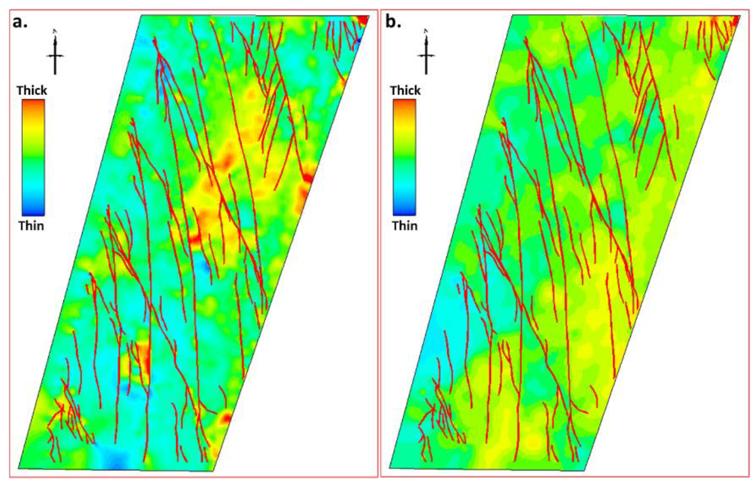
Tidal erosive surfaces identified from cores in Unit 4 in the south of the field can also be proved in a thickness map derived from seismic data. The thickness map of Unit 4 shows that thick depositions developed in the north of the field, while thinner depositions are in the south (Figure 7a). However, the thickness map of Unit 5 shows an inverse thickness trend (Figure 7b). To interpret the reason of the inverse thickness trends in Unit 4 and Unit 5, formation thickness maps using the method of flattening the lower MFS (MFS2) at the bottom of the hydrocarbon-bearing interval are generated. This method reflects probable palaeogeomorphy features prior to the deposition of each unit and renders a probable transition in depositional preferences during the deposition of Unit 4 to Unit 5.
The thickness from the MFS to Unit 3 (prior to Unit 4) is larger in the south and it becomes smaller to the north (Figure 8a). The larger depositional thickness caused a smaller accommodation space in the south before Unit 4 deposition. Then, in the period of Unit 4 deposition, the local transgressions (tidal affection) that happened in the descending half cycle eroded deposition in the south, while the sediments filled the accommodation space and made a possible height of palaeogeomorphy in the north prior to the Unit 5 period. During the deposition period of Unit 5, the height of palaeogeomorphy in the north is probably near the proximal, while the distal is in the south of the field. Therefore, during the depositional period of Unit 5, thick sediments prefer to exist in the north, while the deposition is thinner in the south (Figure 8b).

4.2. Postdeposition Diagenesis

Postdeposition diagenesis of clay mineral cementations widely occurs in Unit 4 and Unit 5. Core samples reveal that minerals include chlorite, ripidolite, and glauconite (Table 2). The clay mineral cementations reduced intergranular pores in reservoir rocks and left abundant micropores, which are unconnected. Four rock types are identified based on degrees of mineral cementation and pore throat structures (Table 3). Type 1 only exists in Unit 5 and it widely distributes in the north of H field. The pore radius with a unimodal distribution ranging from 10 to 100 nm reveals that intergranular pores exist in the type of rock and a displacement pressure of 10 psi suggests that these pores are well connected. The SEM photo also indicates there is nearly no clay mineral cementation in this type.
Bimodal distributions of pore throat radius exist in type 2 to type 4. The increasing portion of micropores and SEM photos indicate that the degree of cementations become stronger from type 2 to type 4. The higher displacement pressures on the capillary pressure curve prove that the micropores are isolated.

4.3. Implication to Reservoirs

The distributions of tight reservoir and the conventional reservoir in H field are controlled by the depositions of geologic units where they exist. In Unit 4, where the tight reservoir develops, thicker sediments prefer to deposit in the north of the field, while sediments became thinner in the south. More sediment accumulation in the south leads to development of a thicker reservoir and the reservoir becomes thinner to the north due to less accumulation. The deposition preference reverses in Unit 5 where the convention reservoir exists. A thicker reservoir develops in the north and it becomes thinner in the south.
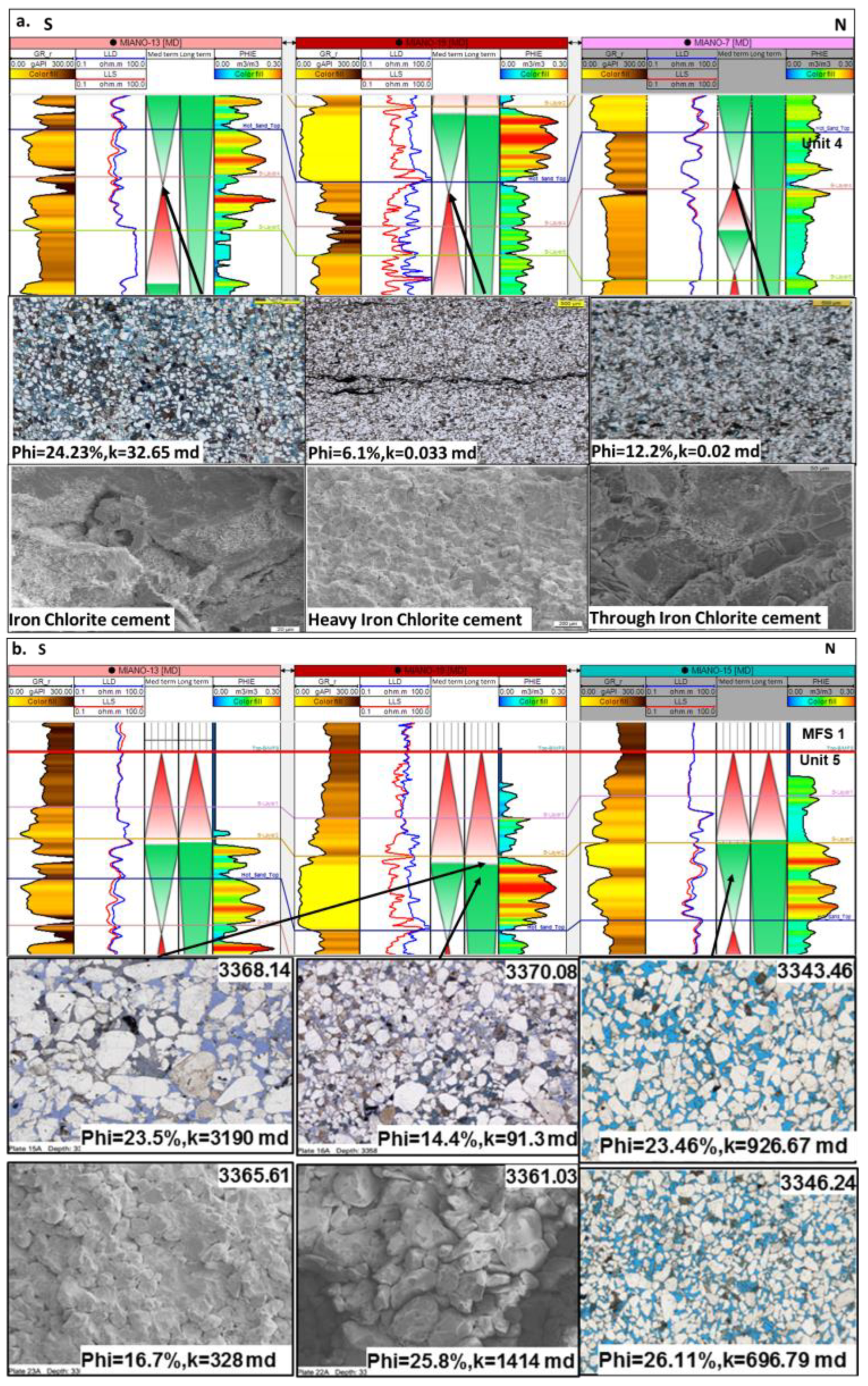
Qualities of the tight reservoir and the conventional reservoir are influenced by the postdepositional diagenesis because strong clay cementation can destroy intergranular pores and heavily reduce pore connectivity in the reservoir. Trends of clay cementation degree in Unit 4 and Unit 5 are inverse. In Unit 4, the degree of cementations become stronger from the south to north, while the degree trend reverses in Unit 5. The permeability of the reservoir reduces from 32.65 mD to 0.02 mD from south to north in Unit 4, while the permeability decreases from 3190 mD to 91.3 mD from north to south in Unit 5 (Figure 9). The trend is proven by rock typing based on thin section, SEM, and pore radius analysis.

5. Static Reservoir Model

5.1. Structural Framework and Grid System

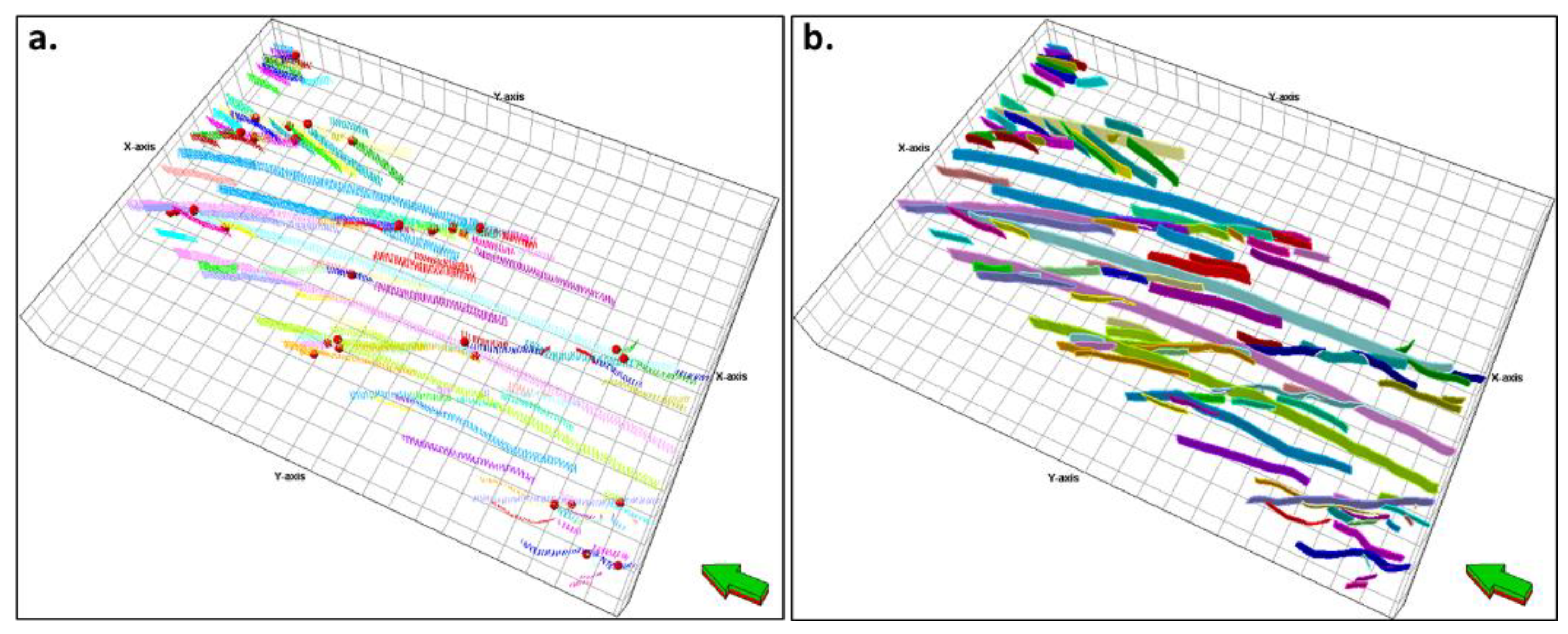
The whole gas-bearing interval, including the conventional and the tight gas reservoir, is compiled into the static reservoir model. Therefore, a structural framework contains top surfaces of each geologic unit and faults developed in these units. The structural framework adopts faults, which are derived from seismic data, and fault contacts are tested in 3D space to eliminate unnatural anomalies, including fault proximity, discontinuous fault interaction, and acute-angled intersections (Figure 10a). Iterations between contact test and seismic interpretation are applied to obtain expected fault planes in the structural framework (Figure 10b).
An orthometric grid system is established in the structural model considering the trends of strike faults, reservoir development, and computing efficiency. Cells in the grid system have a rotation of 20 degrees, which are approximately parallel to the trend of major strike faults in the field (Figure 11). The cell rotation will reduce cell mutation at the intersections between the fault and the grid system. Vertical zonation of the grid system five zones, which correspond to the five geologic units defined in the geological analysis and vertical layering of each zone, are based on the thickness and reservoir development of each unit. The Unit 4 (Zone 4) and Unit 5 (Zone 5), where gas reservoirs develop, have the most layers among the five geologic units in the model. Subzones are further divided in these two units, honoring small layer tops in wells. The vertical resolution of these units is approximately 0.5 m, while other zones, where there are no proved gas intervals, have fewer vertical layers, which means lower vertical resolutions (Table 4). Different vertical layering not only captures heterogeneities of zones where reservoirs develop but also satisfies the efficiency of model computation. The 100 m × 100 m horizontal resolution is adopted in the model.

5.2. Property Model

Reservoir property modeling in H field has challenges. These challenges are (1) the sparse and irregular well coverage in the field, (2) high horizontal reservoir heterogeneity away from wells [32], and (3) the inverse quality trends exist in the conventional and the tight reservoirs. Therefore, property modeling exclusively using geostatistical simulation makes the static model unpredictive [33]. Considering the limitation of geostatistical simulation method and the geologic nature of the two reservoir units, the property models, including shale volume (Vsh), porosity (φ), permeability (k), and rock type (RT), are built by using a geologic genesis rule-based modeling method. There are three benefits of using the static model by using the method. The most important one is that the geologic genesis rule-based method can distinguish the tight reservoir in Unit 4 and the conventional reservoir in Unit 5 based on depositional processes in temporal sequence [32]. Then, the reverse reservoir variation depositional trends in the two reservoirs can be compiled into the static model. The second benefit is that the method can render reservoir distributions constrained by sedimentary facies. Thus, the static model can realize the lateral heterogeneity of reservoirs, especially for the area without well coverage, and it can be more predictive for the following numerical simulations. The last benefit of the modeling method is that sensitive subsurface uncertainties can be captured more easily beyond singly using geostatistical methods.
The geologic genesis analysis reveals that the distributions of the tight and conventional reservoirs are controlled by deposition. The reverse trends of reservoir quality are influenced by postdeposition clay cementations. Therefore, Vsh is considered as a major indictor to reflect reservoir qualities. The Vsh model is built under the constraint of a trend derived from P-wave impedances (P-imp) inversion, which is confirmed to be closely related to facies in much of the previous research [34,35,36,37]. The P-imp has different probability distribution functions (PDF) in each facies for both Unit 4 and Unit 5 (Figure 12). The trend used for constraint is generated by a normalization processing for P-imp volume. The Vsh of the reservoir in each well is generated from petrophysical results and it is upscaled into the modelling cellular system by arithmetic algorithm. The upscaled Vsh is propagated using sequential Gaussian simulation (SGS) under the constraint of P-imp trend. The facie-constrained Vsh model has a corresponding feature to the facies distribution in both the tight and the conventional reservoirs. In Unit 4, where the tight reservoir develops, the Vsh distribution presents a scattered morphology cut by tidal channels which reflect the local transgression in the southeast (Figure 13a). Because Unit 4 and Unit 5 have different sedimentary facies, the Vsh model has a different distribution morphology in Unit 5. Vsh in Unit 5 presents a higher continuity, which indicates sheet-like deposition in a higher accommodation space after the middle-scale, descending half cycle in the upper of Unit 5 (Figure 13b). A SW–NE-directed cross section generated in the model. The cross section reveals that the Vsh decreases from north to south in Unit 4 (Figure 14a), while the trend reverses in the lower part of Unit 5 where the conventional reservoir exists (Figure 14b). The variation in Vsh in the two units realizes the inverse reservoir quality trends in the tight and the conventional reservoirs.
The Vsh gives an impact to porosities of the reservoirs. Although the total porosity of the reservoir quality rocks has a range of 15% to 30%, clay cementations heavily reduced intergranular pores and left abundant, unconnected micropores. The porosity models of the reservoirs are under the constraint of Vsh in each facies. Similar to P-imp, Vsh has different PDF in each facies. The Vsh property model in each facies is converted into a trend volume by a normalization process (Figure 15). The porosities of reservoirs are generated from petrophysical interpretation in each well and they are upscaled into the cellular system by using arithmetic algorithm. The porosity model is then propagated using sequential Gaussian simulation (SGS) under the Vsh trend constraint (Figure 16).
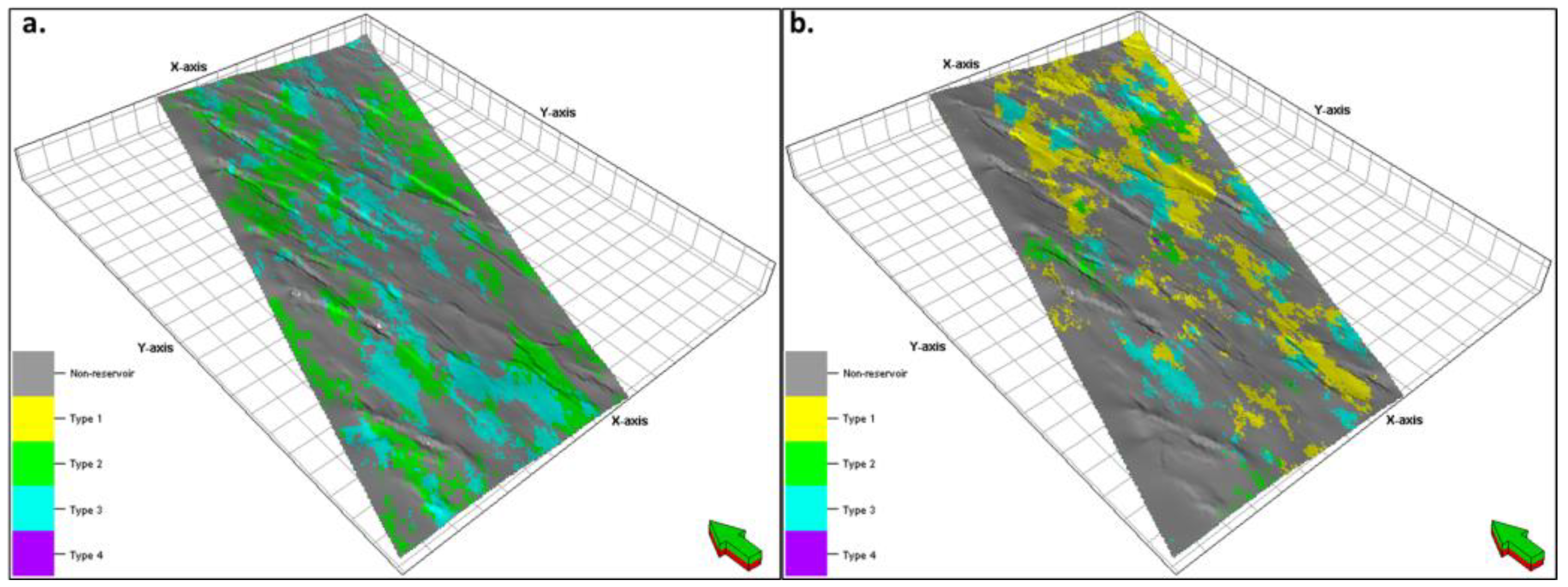
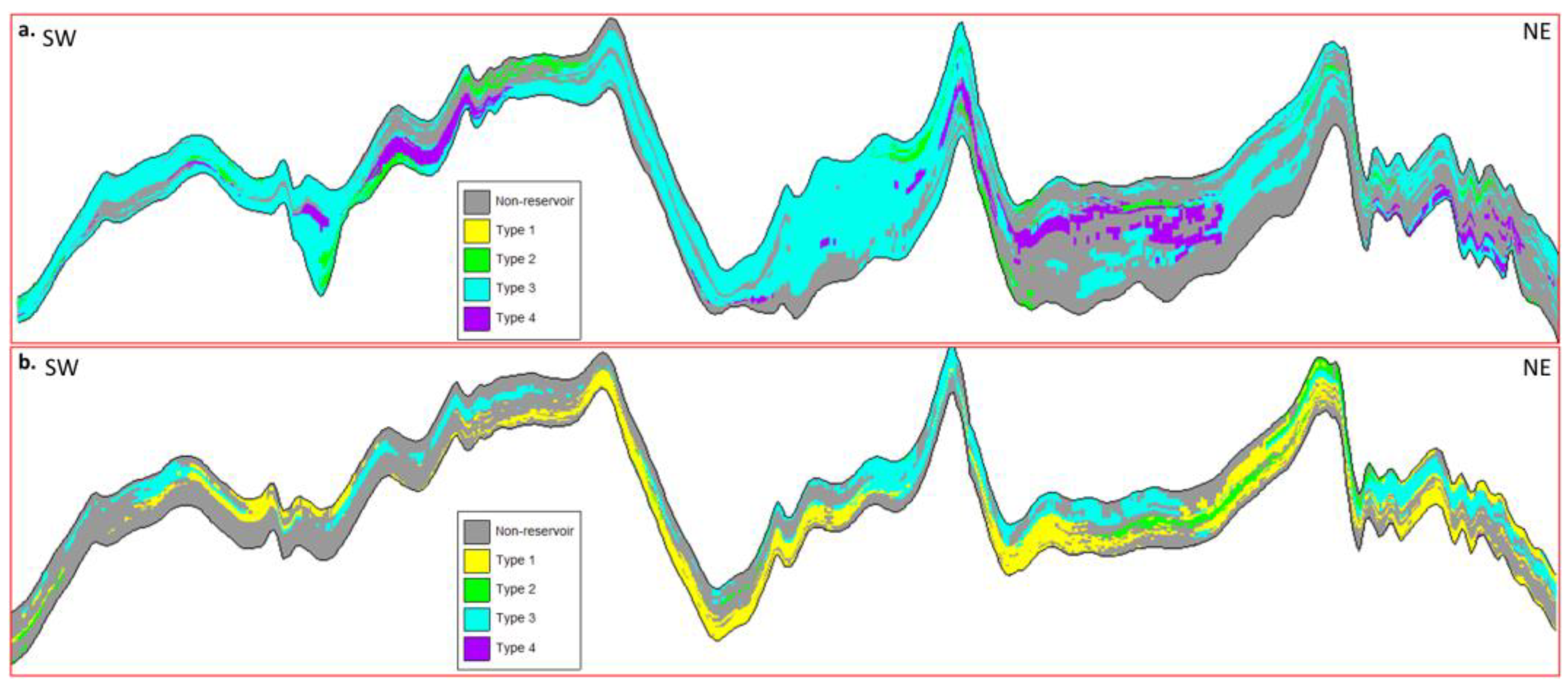
The rock typing for the reservoirs in petrophysical analysis under the consideration of degrees of mineral cementation and pore throat structures. Four rock types are identified in wells and the quality of those rock types decreases from type 1 to type 4. The geologic genesis analysis reveals that the main reason for rock type variation is the clay cementation. Therefore, the rock type model can also be constrained by Vsh model. The Vsh model is converted into a discrete trend by using a cutoff value of 40% (Figure 17). The discrete rock types in each well are upscaled into the cellular system using “the most of” method, and then propagated using sequential indicator simulations (SIS) under the constraint of the discrete trend (Figure 18). The rock type distributions in the model are in accord with the understandings in geologic genesis analysis. Type 1, which is the best quality rock, only exists in Unit 5 where the convention reservoir develops. Type 2 to type 4 are included in Unit 4 where the tight reservoir exists. Type 2 in the tight reservoir mainly concentrates in the south of the field. A SW–NE-directed cross section is generated to show the rock type variation in these two reservoirs (Figure 19).
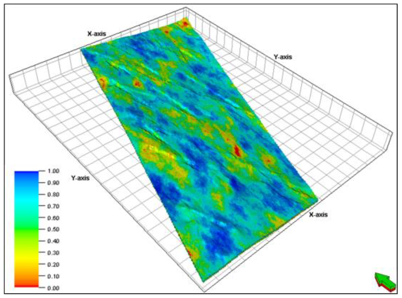
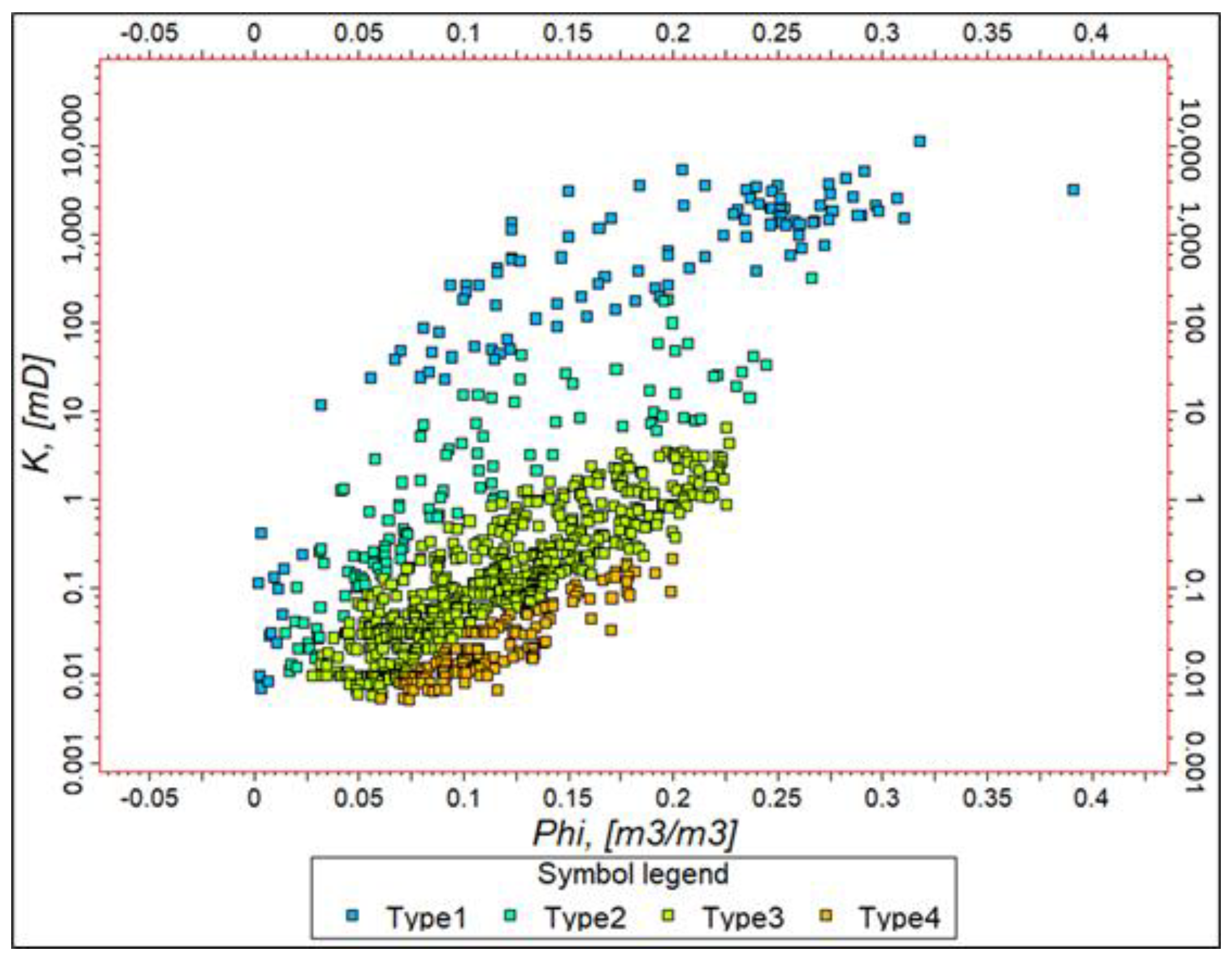
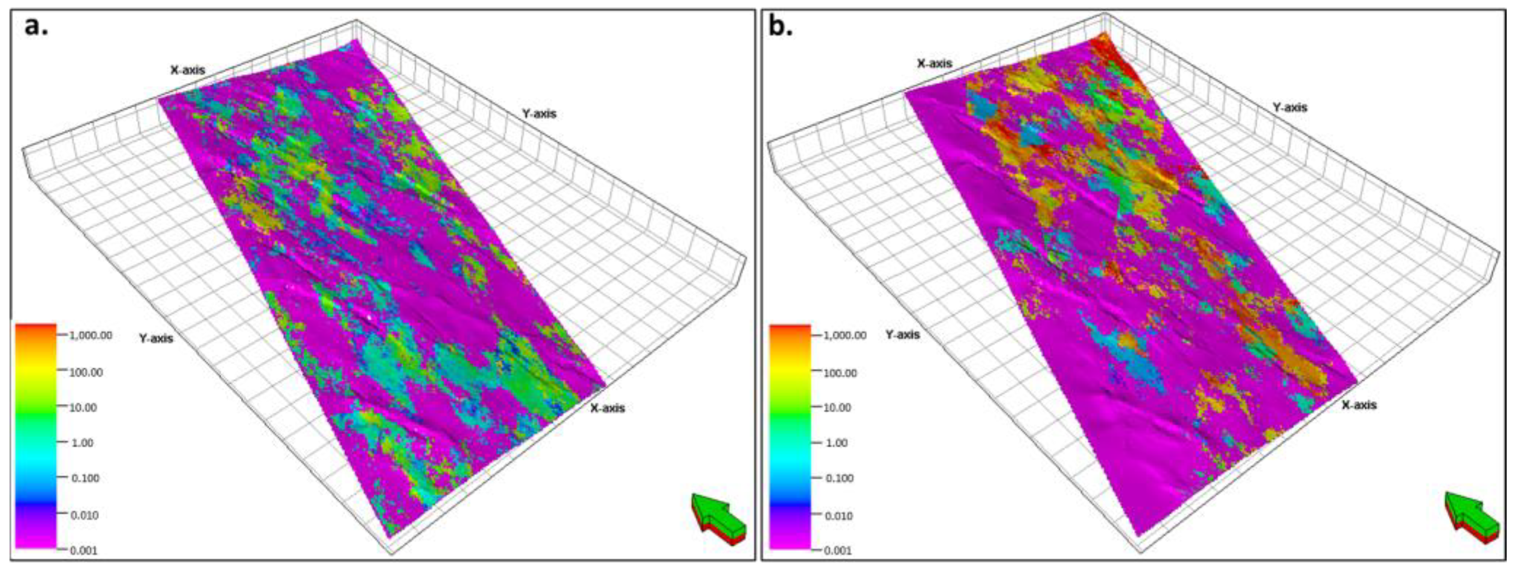
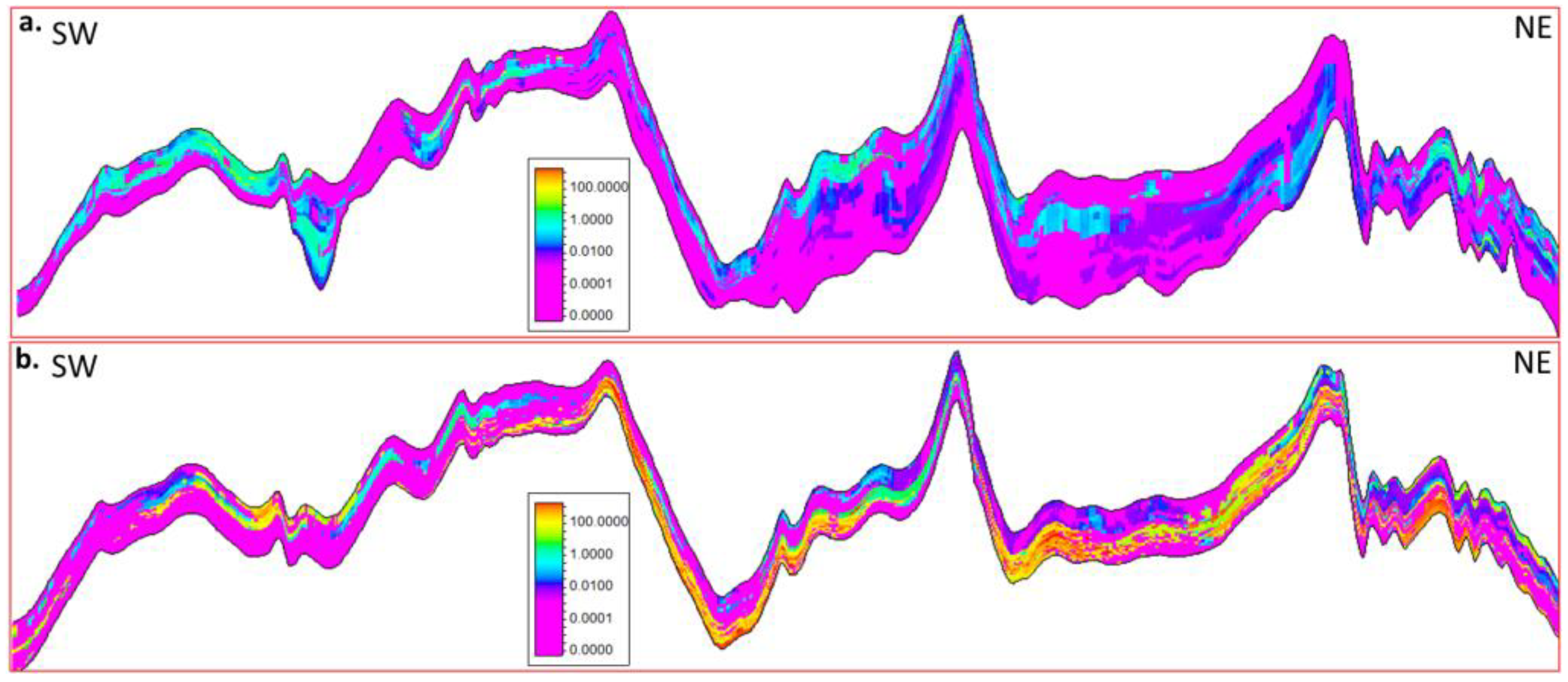
Different φ-k relations are a common indicator of different reservoir rock types [37,38,39,40,41]. The permeability model is calculated based on the φ-k relations of the four rock types (Figure 20). The permeability model also presents the inverse trends of reservoir quality in the conventional and the tight reservoir (Figure 21). In Unit 5, the high permeability concentrates in the north of the field, while the permeability decreases from south to north in Unit 4. A NW–SE-directed cross section illustrates the permeability variation trend in the two reservoirs (Figure 22).
Sw model is calculated by SHF of the four rock types. The Leverett-J function [27], shown as Equation (1), is adopted in the Sw calculation.
S W   =   A   ×   J B   +   C
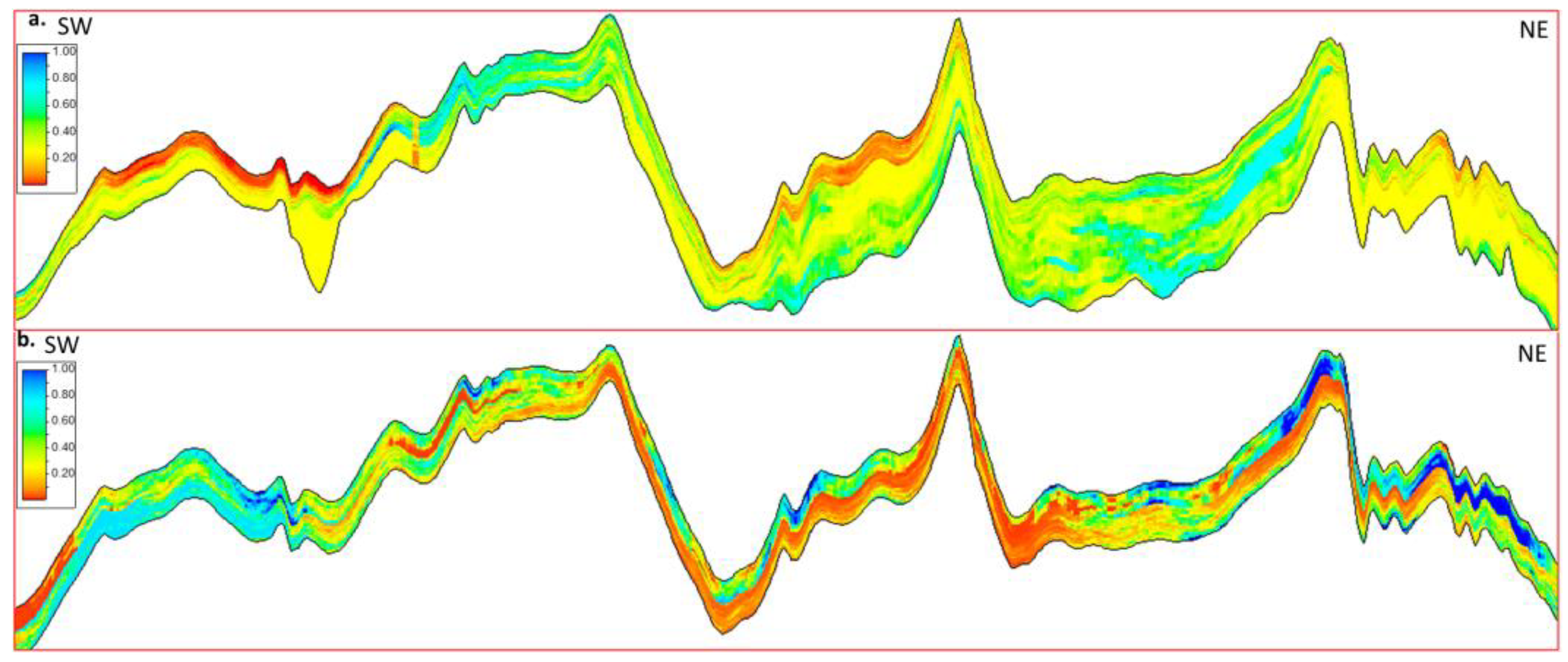
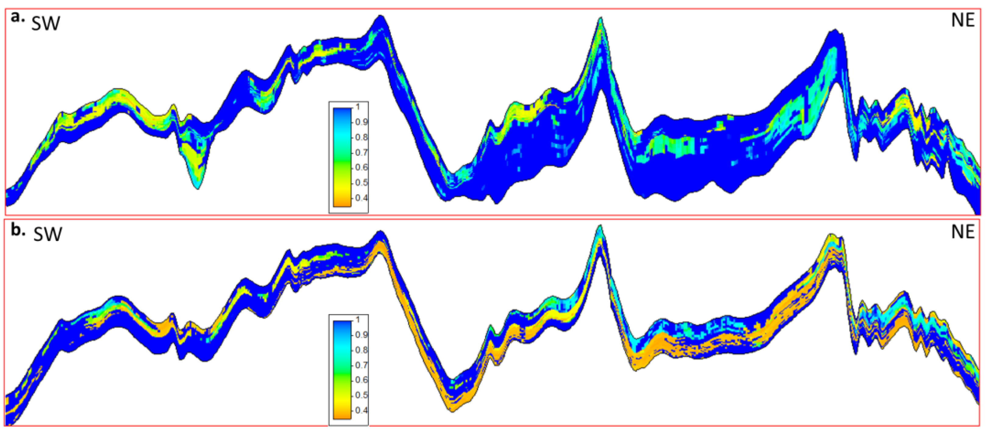
The free water level (FWL) is identified based on fluid interpretation result in wells. The only well with interpreted water layers is located in the north of the field. The free water level is defined at −3320 m SSTVD in this well (Figure 23). The water saturation reveals that the north of the conventional gas unit has relatively lower water saturation than the south. However, the tight reservoir unit has an inverse trend of water saturation compared to the conventional gas unit (Figure 24).
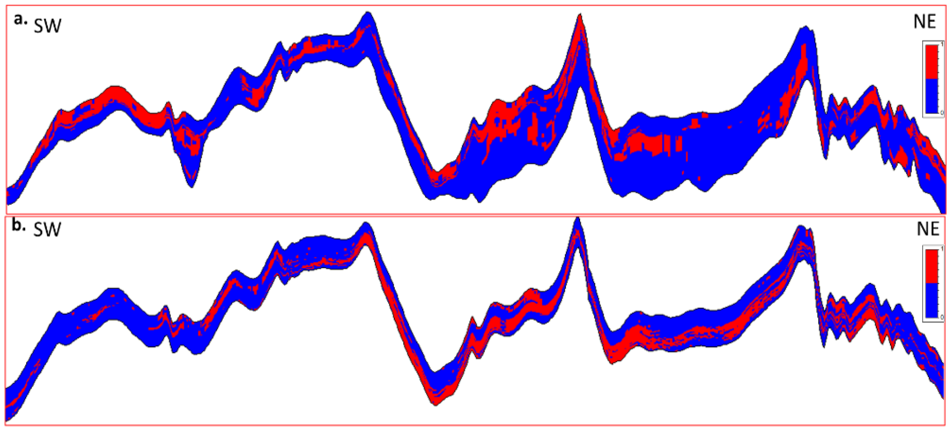
Cut-off values from petrophysical analysis are adopted to generate the net to gross (NTG) model. The cut-off values are from two parameters: Vsh and porosity. The NTG model reveals that most net pay in the conventional reservoir concentrates in the north of the field, while most net pay in the tight reservoir is in the south (Figure 25).

6. Post-Modeling Analysis

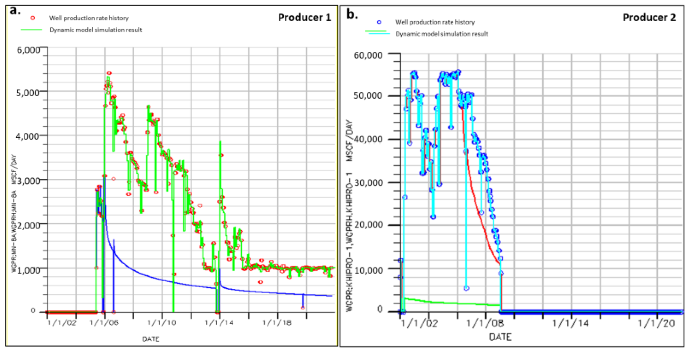
Post-modeling operations aim at to test the model accuracy, to refine the model, and to summarize the model [2]. The post-modeling operation for the static models includes model accuracy testing using producer performance in dynamic simulation [42,43,44] and reservoir property uncertainty analysis based on the static reservoir model. The reservoir properties (porosity and permeability) were imported into a commercial numerical simulator of Eclipse and a numerical simulation was conducted to calculate gas production rates of the two producers. Then, comparisons were made between the calculated gas production rate and the rate actually observed in wells (Figure 26). The gas production rates observed in producer 1 ranges from 800 to 5400 million standard cubic feet (MSCF), with a decreasing trend (green point in Figure 26a) from year 2016 to 2018. The simulated gas production rate of producer 1 (red line in Figure 26a) matches the actual gas production observed in the well. The gas production rates observed in producer 2 ranges from 1200 to 9800 MSCF from year 2010 to 2020, also with a decreasing trend (green point in Figure 26b). The simulated gas production rate of producer 2 (red line in Figure 26b) also matches the actual gas production observed in the well. History-matching performance for the only two producers that have production in the tight gas reservoir in the field is good. The good history-matching results of the producers indicate that the static model satisfies the accuracy for production forecast.
The reservoir properties are analyzed by an integration of the reservoir model and understandings from geologic genesis analysis. The geologic genesis analysis reveals that the conventional and the tight reservoirs are both controlled by deposition and postdeposition diagenesis. Therefore, the biggest subsurface uncertainty is the variation in Vsh. The porosity is impacted by Vsh because the clay cementations heavily reduced intergranular pores. The porosity is also considered as a reservoir property uncertainty. The Sw, which directly relates to GIIP of a reservoir, is decided by free water level (FWL) depth. The FWL variations should be regarded to be another reservoir property uncertainty. A Monte Carlo simulation is conducted on the static model. In the simulation, Vsh and porosity both have a variation range of ±10%. The FWL is set to a variation of ±10 m. The simulation results show that Vsh with ±10% variation range caused the gas initial in place (GIIP) variation range from 7.4 × 10¹⁰ standard cubic meters (sm3) to 8.35 × 10¹⁰ sm3. However, FWL with ±10% variation range only caused a variation range in GIIP from 7.95 × 10¹⁰ sm3 to 8.75 × 10¹⁰ sm3. The porosity with ±10% variation range caused the smallest variation range in GIIP, with values from 7.95 × 10¹⁰ sm3 to 8.35 × 10¹⁰ sm3. The different GIIP variation ranges caused by changes in these properties (Vsh, porosity, and FWL) are a quantitative way to measure their contribution to uncertainties in reservoir modeling. The shale volume has the largest contribution to the uncertainty in the reservoir model, while the porosity and FWL contribute to the uncertainty of the reservoir model not as much as Vsh (Figure 27).

7. Conclusions

The greatest challenge in the reservoir characterization and modeling for the hydrocarbon-bearing interval of Miano gas field is the reversed trend in reservoir quality of the tight reservoir and the overlying conventional reservoir. The geologic genesis analysis mainly depending on observations from cores and borehole logs of 11 wells is performed to understand the depositional process of the two reservoirs in Miano gas field. Core data and the thickness map suggest multiple depositional facies exist in the hydrocarbon-bearing intervals compared to previous research, which only described single facies, based on seismic attribute analysis [14,15,45,46,47]. The tight gas reservoir is tidal-influenced shore facies and it experienced a local transgression in the southern area, which has a small accommodation space. The local transgression leads to a smaller reservoir thickness of the tight gas reservoir in the south and a switch in palaeogeomorphy height before the deposition of the conventional reservoir, which is fluvial-influenced delta front facies, also proven by core data and well logs. Therefore, during the depositional period of the convention reservoir, thicker sediments prefer to exist in the north, while the deposition is thinner in the south. The conventional and the tight gas reservoir both experience postdeposition diagenesis. Thin sections, SEM, and pore radius analysis reveal that trends in clay cementation degree in the conventional and the tight reservoir are inverse.
The geologic genesis analysis reveals that the reversed reservoir quality trends in the conventional and the tight gas reservoirs are controlled by the deposition and the postdeposition genesis jointly. The static reservoir model is built following the understanding from the geologic genesis analysis. Compared to the previous studies that mainly relied on 2D seismic data [12,48], the structure framework of the model integrates the faults and formation horizons from the latest 3D seismic interpretation. The property models realize the reversed quality trend in the two reservoir units. The average shale volume in the conventional reservoir changes from 10% to 30 % from northwest to southeast through the Miano gas field, while it changes from 50% to 20% from northwest to southeast. The reversed trend also developed in the porosities and permeabilities of the two reservoirs. The average porosity increased from 5% to 25% from northwest to southeast through the gas field in the conventional reservoirs but it decreased from 10% to 30% in the tight reservoir in the same direction. The average permeability increased from 1 mD to 50 mD from northwest to southeast through the gas field in the conventional reservoirs and it decreased from 10 mD to 0.1 mD in the tight gas reservoir in the same direction.
The accuracy of the static model is tested by history-matching performance for current producers in numerical simulation. The gas production rate of two producers were simulated using the reservoir model. The actual observed gas production rate of one producer varies from 800 to 5400 MSCF and the other one ranges from 1200 to 9800 MSCF. The simulated gas production has a good match with actual observed gas production rate in wells. The good history-matching result of the two current producers indicates that the model can reach the accuracy for production forecast.
The geologic genesis analysis and the static model reveals that the greatest uncertainty for reservoir GIIP is the Vsh variation. Variations of ±10% in shale volume cause the GIIP changes from 7.4 × 10¹⁰ sm3 to 8.35 × 10¹⁰ sm3. The variations in porosity and FWL also render an impact to the GIIP uncertainty. FWL with ±10 m variations only caused a change in GIIP from 7.95 × 10¹⁰ sm3 to 8.75 × 10¹⁰ sm3. The average porosity with ±10% variation range caused the smallest variation range in GIIP, with values from 7.95 × 10¹⁰ sm3 to 8.35 × 10¹⁰ sm3. The gas contribution of each reservoir can also be inferred. In the south of the field, the tight gas reservoir probably contributes more gas, while minor gas may exist in the conventional reservoir due to the poor reservoir quality. However, the conventional reservoir could contribute more gas in the north and nearly no gas contribution in the tight gas reservoir in the same area.

Author Contributions

The article is an integration of multiple disciplines and all authors contribute to the research. Idea and methodology, C.Z., C.Y., X.M. and J.C.; static modeling, C.Y.; basic geological study, C.Y., C.Z., X.W. and J.Y.; petrophysical analysis, W.Y.; numerical simulation and history matching, J.C.; article review and advice, P.D., C.Z. and Q.N. All authors have read and agreed to the published version of the manuscript.

Funding

This research was funded by the National Natural Science Foundation of China (Grant No. 42141009).

Institutional Review Board Statement

Not applicable.

Informed Consent Statement

Not applicable.

Data Availability Statement

Data not available due to commercial restrictions.

Conflicts of Interest

The authors declare no conflict of interest.

References

  1. Harris, P.M.G. Giant Hydrocarbon Reservoirs of the World: From Rocks to Reservoir Characterization and Modeling. Memoir/American Association of Petroleum Geologists 88; American Association of Petroleum Geologists: Tulsa, OK, USA, 2006. [Google Scholar]
  2. Pyrcz, M.J.; Deutsch, C.V. Geostatistical Reservoir Modeling, 2nd ed.; Oxford University Press: Oxford, NY, USA, 2014. [Google Scholar]
  3. Falivene, O.; Arbues, P.; Gardiner, A.; Pickup, G.E.; Muñoz, J.A.; Caberra, L. Best Practice Stochastic Facies Modeling from a Channel-Fill Turbidite Sandstone Analog (the Quarry Outcrop, Eocene Ainsa Basin, Northeast Spain). AAPG Bull. 2006, 90, 1003–1029. [Google Scholar] [CrossRef]
  4. Azeem, T.; Chun, W.Y.; Lisa, M.; Khalid, P.; Qing, L.X.; Ehsan, M.I.; Munawar, M.J.; Wei, X. An Integrated Petrophysical and Rock Physics Analysis to Improve Reservoir Characterization of Cretaceous Sand Intervals in Middle Indus Basin, Pakistan. J. Geophys. Eng. 2017, 14, 212–225. [Google Scholar] [CrossRef]
  5. Dar, Q.U.Z.; Renhai, P.; Ghazi, S.; Ahmed, S.; Ali, R.I.; Mehmood, M. Depositional Facies and Reservoir Characteristics of the Early Cretaceous Lower Goru Formation, Lower Indus Basin Pakistan: Integration of Petrographic and Gamma-Ray Log Analysis. Petroleum 2021. [Google Scholar] [CrossRef]
  6. Raza, M.; Khan, F.; Khan, M.; Riaz, M.; Khan, U. Reservoir Characterization of the B-Interval of Lower Goru Formation, Miano 9 and 10, Miano Area, Lower Indus Basin, Pakistan. Environ. Earth Sci. Res. J. 2020, 7, 18–32. [Google Scholar] [CrossRef]
  7. Azeem, T.; Yanchun, W.; Khalid, P.; Xueqing, L.; Yuan, F.; Lifang, C. An Application of Seismic Attributes Analysis for Mapping of Gas Bearing Sand Zones in the Sawan Gas Field, Pakistan. Acta Geod. Et Geophys. 2016, 51, 723–744. [Google Scholar] [CrossRef] [Green Version]
  8. Zareef, F.; Khan, N.; Asim, S.; Naseer, M.T. An Integrated Study to Analyze the Reservoir Potential Using Stochastic Inversion, Model Based Inversion and Petrophysical Analysis: A Case Study from The Southern Indus Basin, Pakistan. J. Earth Sci. 2016, 24. [Google Scholar] [CrossRef]
  9. Krois, P.; Mahmood, T.; Milan, G. Miano Field, Pakistan, A Case History of Model Driven Exploration. In Proceedings Pakistan Petroleum Convention; Pakistan Association of Petroleum Geoscientists (PAPG): Islamabad, Pakistan, 1998; Volume 98, pp. 112–131. [Google Scholar]
  10. Shar, A.M.; Mahesar, A.A.; Chandio, A.; Memon, K.R. Impact of confining stress on permeability of tight gas sands: An experimental study. J. Petrol. Explor. Prod. Technol. 2017, 7, 717–726. [Google Scholar] [CrossRef] [Green Version]
  11. Ali, M.; Shar, A.M.; Mahesar, A.A.; Al-Yaseri, A.; Yekeen, N.; Memon, K.R.; Keshavarz, A.; Hoteit, H. Experimental evaluation of liquid nitrogen fracturing on the development of tight gas carbonate rocks in the Lower Indus Basin, Pakistan. Fuel 2022, 309, 122192. [Google Scholar] [CrossRef]
  12. Jadoon, S.-U.K.; Mehmood, M.F.; Shafiq, Z.; Jadoon, I.A.K. Structural Styles and Petroleum Potential of Miano Block, Central Indus Basin, Pakistan. Int. J. Geosci. 2016, 7, 1145–1155. [Google Scholar] [CrossRef] [Green Version]
  13. Lolon, E.; Quirk, D.J.; Enzendorfer, C.K.; Bregar, U.B.; Qayamuddin, S.; Mayerhofer, M.J.; Cipolla, C.L. Hydraulic Fracture Feasibility, Design, On-Site Supervision and Post Job Evaluation in Southeast Pakistan Gas Field. In Proceedings of the SPE Annual Technical Conference and Exhibition, Denver, CO, USA, 21–24 September 2008. [Google Scholar] [CrossRef]
  14. Naseer, M.T.; Asim, S. Application of Instantaneous Spectral Analysis and Acoustic Impedance Wedge Modeling for Imaging the Thin Beds and Fluids of Fluvial Sand Systems of Indus Basin, Pakistan. J. Earth Syst. Sci. 2018, 127, 97. [Google Scholar] [CrossRef] [Green Version]
  15. Naseer, M.T.; Asim, S. Detection of Cretaceous Incised-Valley Shale for Resource Play, Miano Gas Field, SW Pakistan: Spectral Decomposition Using Continuous Wavelet Transform. J. Asian Earth Sci. 2017, 147, 358–377. [Google Scholar] [CrossRef]
  16. Farah, A.; De Lawrence, R.; De, J. An Overview of the Tectonics of Pakistan. In Marine Geology and Oceanography of Arabian Sea and Coastal Pakistan; New York (USA) Van Nostrand and Reinhold Cooperation: New York, NY, USA, 1984; pp. 161–176. [Google Scholar]
  17. Kadri, I.B. Petroleum Geology of Pakistan; Pakistan Petoleum Ltd.: Karachi, Pakistan, 1995. [Google Scholar]
  18. Wandrey, C.J.; Law, B.E.; Haider, A.S. Sembar Goru/Ghazij Composite Total Petroleum System, Indus and Sulaiman-Kirthar Geologic Provinces, Pakistan and India; U.S. Geological Survey Bulletin 2208-C; U.S. Geological Survey: Reston, VA, USA, 2004. [Google Scholar]
  19. Kazmi, A.H.; Jan, M.Q. Geology and Tectonics of Pakistan; Graphic Publishers: Karachi, Pakistan, 1997. [Google Scholar]
  20. Berger, A.; Gier, S.; Krois, P. Porosity-Preserving Chlorite Cements in Shallow-Marine Volcaniclastic Sandstones: Evidence from Cretaceous Sandstones of the Sawan Gas Field, Pakistan. AAPG Bull. 2009, 93, 595–615. [Google Scholar] [CrossRef] [Green Version]
  21. Cantrell, D.; Swart, P.; Hagerty, R. Genesis and Characterization of Dolomite, Arab-D Reservoir, Ghawar Field, Saudi Arabia. GeoArabia 2004, 9, 11–36. [Google Scholar] [CrossRef]
  22. Li, S.; Li, S.; Zhou, X.; Ma, X.; Guo, R.; Zhang, J.; Chen, J. The Genesis Model of Carbonate Cementation in the Tight Oil Reservoir: A Case of Chang 6 Oil Layers of the Upper Triassic Yanchang Formation in the Western Jiyuan Area, Ordos Basin, China. Open Geosci. 2020, 12, 1105–1115. [Google Scholar] [CrossRef]
  23. Aleksandrov, V.; Kadyrov, M.; Ufelman, Z.; Golozubenko, V.; Kopyrin, V. Oil and Gas Reef Facies Reservoir 3D Geological Modeling. Key Eng. Mater. 2018, 785, 118–124. [Google Scholar] [CrossRef]
  24. Olsen, H.; Briedis, N.A.; Renshaw, D. Sedimentological Analysis and Reservoir Characterization of a Multi-Darcy, Billion Barrel Oil Field—The Upper Jurassic Shallow Marine Sandstones of the Johan Sverdrup Field, North Sea, Norway. Mar. Pet. Geol. 2017, 84, 102–134. [Google Scholar] [CrossRef]
  25. Cross, T.A. High-Resolution Stratigraphic Correlation from the Perspective of Base-Level Cycles and Sediment Accommodation. In Proceedings of the Northwestern European Sequence Stratigraphy Congress, Stavanger, Norway, 1–3 February 1993; pp. 105–123. [Google Scholar]
  26. Cross, T.; Bake, M.; Chapin, M.; Clark, M.; Gardner, M.; Hanson, M.; Lessenger, M. Application of High-Resolution Sequence Stratigraphy to Reservoir Analysis. In Subsurface Reservoir Characterization from Outcrop Observation; Editions Technip: Paris, France, 1993; pp. 11–33. [Google Scholar]
  27. Ahmed, T.H. Reservoir Engineering Handbook, 5th ed.; Gulf Professional Publishing: Cambridge, MA, USA, 2019. [Google Scholar]
  28. Zheng, R.C.; Wen, G.H.; Li, F.J. High-Resolution Sequence Stratigraphy; Geological Publishing House: Beijing, China, 2010. [Google Scholar]
  29. Smewing, J.D.; Warburton, J.; Daley, T. Sequence Stratigraphy of the Southern Kirthar Fold Belt and Middle Indus Basin, Pakistan. Tecton. Clim. Evol. Arab. Sea Reg. 2002, 195, 273. [Google Scholar] [CrossRef]
  30. Ahmad, N.; Fink, P.; Sturrock, S.; Mahmood, T.; Ibrahim, M. Sequence Stratigraphy as Predictive Tool in Lower Goru Fairway, Lower and Middle Indus Platform. In The Annual Publication of SPE-PAPG Conference; Society of Petroleum Engineering: Islamabad, Pakistan, 2012. [Google Scholar]
  31. Catuneanu, O. Principles of Sequence Stratigraphy, 1st ed.; Developments in Sedimentology 58; Elsevier: Amsterdam, The Netherlands; Boston, MA, USA, 2006. [Google Scholar]
  32. Pyrcz, M.J.; Sech, R.P.; Covault, J.A.; Willis, B.J.; Sylvester, Z.; Sun, T.; Garner, D. Stratigraphic Rule-Based Reservoir Modeling. Bull. Can. Pet. Geol. 2015, 63, 287–303. [Google Scholar] [CrossRef]
  33. Guo, Z.; Sun, L.; Jia, A.; Lu, T. 3-D Geological Modeling for Tight Sand Gas Reservoir of Braided River Facies. Pet. Explor. Dev. 2015, 42, 83–91. [Google Scholar] [CrossRef]
  34. Xiuwei, Y.; Zhu, P. A Fast Stochastic Impedance Inversion under Control of Sedimentary Facies Based on Geostatistics and Gradual Deformation Method. In SEG Technical Program Expanded Abstracts; Society of Exploration Geophysicists: Dallas, TX, USA, 2016; pp. 3746–3750. [Google Scholar] [CrossRef]
  35. Rowbotham, P.S.; Marion, D.; Lamy, P.; Insalaco, E.; Swaby, P.A.; Boisseau, Y. Multidisciplinary Stochastic Impedance Inversion: Integrating Geological Understanding and Capturing Reservoir Uncertainty. Pet. Geosci. 2003, 9, 287–294. [Google Scholar] [CrossRef]
  36. Cooke, D.A.; Schneider, W.A. Schneider. Generalized Linear Inversion of Reflection Seismic Data. Geophysics 1983, 48, 665–676. [Google Scholar] [CrossRef]
  37. Walter, D.J.; Lambert, D.N.; Young, D.C. Sediment Facies Determination Using Acoustic Techniques in a Shallow-Water Carbonate Environment, Dry Tortugas, Florida. Mar. Geol. 2002, 182, 161–177. [Google Scholar] [CrossRef]
  38. Radwan, A.A.; Abdelwahhab, M.A.; Nabawy, B.S.; Mahfouz, K.H.; Ahmed, M.S. Facies Analysis-Constrained Geophysical 3D-Static Reservoir Modeling of Cenomanian Units in the Aghar Oilfield (Western Desert, Egypt): Insights into Paleoenvironment and Petroleum Geology of Fluviomarine Systems. Mar. Pet. Geol. 2022, 136, 105436. [Google Scholar] [CrossRef]
  39. Pittman, E.D. Relationship of porosity to permeability to various parameters derived from mercury injection–capillary pressure curves for sandstone. AAPG Bull. 1992, 76, 191–198. [Google Scholar]
  40. Porras, J.C.; Campos, O. Rock Typing: A Key Approach for Petrophysical Characterization and Definition of Flow Units, Santa Barbara Field, Eastern Venezuela Basin. In Proceedings of the SPE Latin American and Caribbean Petroleum Engineering Conference, Buenos Aires, Argentina, 15–18 April 2007; OnePetro: Denver, CO, USA, 2001. [Google Scholar] [CrossRef]
  41. Al-Jawad, S.N.; Saleh, A.H. Flow Units and Rock Type for Reservoir Characterization in Carbonate Reservoir: Case Study, South of Iraq. J. Pet. Explor. Prod. Technol. 2020, 10, 1–20. [Google Scholar] [CrossRef] [Green Version]
  42. Shekhar, R.; Naqbi, A.A.; Obeta, C.; Ottinger, G.; Herrmann, R.; Obara, T.; Almazrouei, S.J.; Maqrami, Z.N.; Neyadi, A.A.; Edwards, E.; et al. Implementation of High Resolution Diagenetic Features into the Static and Dynamic Reservoir Models of a Giant Offshore Oil Field, Abu Dhabi. In Proceedings of the Abu Dhabi International Petroleum Exhibition & Conference, Abu Dhabi, United Arab Emirates, 15 November 2017; SPE: Abu Dhabi, United Arab Emirates, 2017. [Google Scholar] [CrossRef]
  43. Pamungkas, S.; Flavien, M.; Baptiste, S. Building a Robust Reservoir Model through Full Integration Workflow of Static and Dynamic: A Case Study from a Lower Cretaceous Carbonate Reservoir of a Giant Oil Field, Onshore Abu Dhabi, United Arab Emirates. In Proceedings of the Abu Dhabi International Petroleum Exhibition & Conference, Abu Dhabi, United Arab Emirates, 13 November 2018; SPE: Abu Dhabi, United Arab Emirates, 2018. [Google Scholar] [CrossRef]
  44. Hosseini, S.A.; Lashgari, H.; Choi, J.W.; Nicot, J.-P.; Lu, J.; Hovorka, S.D. Static and Dynamic Reservoir Modeling for Geological CO2 Sequestration at Cranfield, Mississippi, U. S.A. Int. J. Greenh. Gas Control 2013, 18, 449–462. [Google Scholar] [CrossRef]
  45. Tayyab, M.N.; Shazia, A. Application of Spectral Decomposition for the Detection of Fluvial Sand Reservoirs, Indus Basin, SW Pakistan. Geosci. J. 2017, 21, 595–605. [Google Scholar] [CrossRef]
  46. Tayyab, M.N.; Asim, S.; Siddiqui, M.M.; Naeem, M.; Solange, S.H.; Babar, F.K. Seismic Attributes’ Application to Evaluate the Goru Clastics of Indus Basin, Pakistan. Arab. J. Geosci. 2017, 10, 158. [Google Scholar] [CrossRef]
  47. Naseer, M.T.; Asim, S. Continuous Wavelet Transforms of Spectral Decomposition Analyses for Fluvial Reservoir Characterization of Miano Gas Field, Indus Platform, Pakistan. Arab. J. Geosci. 2017, 10, 20. [Google Scholar] [CrossRef]
  48. Khan, M.S.; Masood, F.; Ahmed, Q.; Jadoon, I.A.K.; Akram, N. Structural Interpretation and Petrophysical Analysis for Reservoir Sand of Lower Goru, Miano Area, Central Indus Basin, Pakistan. Int. J. Geosci. 2017, 8, 279–392. [Google Scholar] [CrossRef]
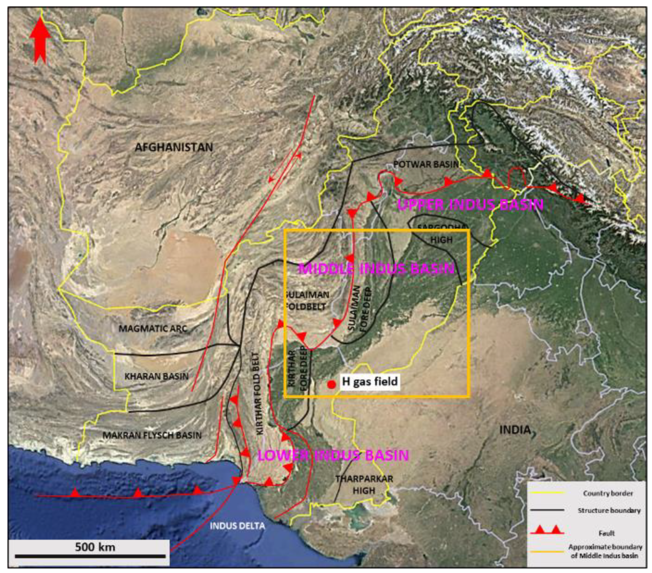
Figure 1. Regional structure map of Indus Basin. The whole Indus Basin is comprised by three subbasins: upper, middle, and lower Indus Basin. Miano gas field is located in the southwest corner of the middle Indus Basin, which is in the east of Kirthar foldbelt and the south of Sulaiman foredeep.
Energies 16 00856 g001
Figure 2. Stratigraphic column of Indus Basin. The tight gas reservoir and the conventional gas reservoir both develop in the B sand in Lower Goru, Cretaceous (cited from [5]).
Energies 16 00856 g002
Figure 3. A general workflow of this study. The workflow includes two major parts: geological genesis analysis, and structural and property modeling. The structural and property modeling is guided by the geological genesis analysis.
Energies 16 00856 g003
Figure 4. The sequence framework of the hydrocarbon-bearing interval of Miano gas field. Two middle-term sequences and five to seven short-term sequences were identified based on cores and well log data. Five geologic units are divided based on cycles. The conventional gas reservoir develops in the lower part of Unit 5 and the overlain tight gas reservoir develops in Unit 4. Some minor gas layers developed in Units 1–3.
Energies 16 00856 g004
Figure 5. A diagram showing the depositional environments during periods of base level ascending and descending. Overall, H field is in a coastal shoreface environment but it presents different features depending on base level variations. Deltaic features developed in the period of base level descending (the red arrow), while tidal-influenced shore facies and storm deposition developed in the period of base level ascending (the blue arrow). Cited from [31].
Energies 16 00856 g005
Figure 6. The core samples and MFI logs in three coring wells in the Miano gas field. The main coring intervals concentrate in Unit 4 and Unit 5. The lithology in Unit 4 is light grey to grey fine-grained sandstone to siltstone with shale layers. The depositional structures in this unit indicate possible local tidal affect. The lithology in Unit 5 presents a trend of deepening upward. Grey coarse-grained sandstone develops at the lower part of the unit and dark grey shaly siltstones with burrows and bioturbations develop in the upper part of the unit.
Energies 16 00856 g006
Figure 7. Thickness maps of Unit 4 (a) and Unit 5 (b). The depositional thicknesses of the two geologic unit have an inverse trend. Unit 4 has thick depositions in the north and thinner depositions in the south. However, in Unit 5, the thick depositions develop in the north and thinner develop in the south of the field.
Energies 16 00856 g007
Figure 8. Thickness maps using the MSF flattening method. The thickness map from Unit 3 to MFS 2 (a) reflects the palaeogeomorphy prior to Unit 4 deposition. The possible height of palaeogeomorphy located in the south of the field where less accommodation space developed. The lower accommodation space makes the sediments in the south easier to be eroded by tidal affection during the ascending half cycle (transgression) in Unit 4. The thickness map from Unit 4 to MFS 2 (b) reflects the palaeogeomorphy post Unit 4 deposition (prior to Unit 5). Comparing with (a), the depositions in the north become thicker (a northward trend of the possible height of palaeogeomorphy) and tidal channel features appear. The coring wells where tidal erosional surfaces were found are also in the tidal channels. The north is where the possible height of palaeogeomorphy is near the proximal and the south is the distal in the deposition of Unit 5.
Energies 16 00856 g008
Figure 9. Reservoir quality variation trends in Unit 4 (a) and Unit 5 (b). In Unit 4, where the tight reservoir develops, the sediments experienced clay mineral cementation. The degree of cementation tends to be heavier from south to north. The reservoir quality of Unit 4 becomes worse from south to north. However, regarding the reservoir quality of Unit 5 where the conventional reservoir develops, the clay mineral cementation is slit in the unit but the variation in cementation can still be identified. The degree of cementation becomes heavier from north to south in Unit 5 and the reservoir quality tends to be worse in the same direction.
Energies 16 00856 g009
Figure 10. Fault sticks from seismic interpretation (colored sticks) and fault break points (red points) identified in wells (a) and fault planes (colored bands) finally adopted in the structural framework (b). The red points and red lines attached on the fault sticks indicate probable unreasonable fault contacts. After multiple fault contact test–seismic iterations, the unreasonable fault contacts are eliminated. The green arrow indicates the north direction.
Energies 16 00856 g010
Figure 11. Degree of cells in the orthometric grid system and the direction of the faults. The degree of the cells is set to 20 to make the cells parallel to the fault direction. This will effectively eliminate cell mutation in the grid system. The color lines are the outlines of fault planes and the red lines represent the fault positions in 2D plane view.
Energies 16 00856 g011
Figure 12. PDFs of the normalized P-impedance trend in different facies in Unit 4 (ac) and Unit 5 (df). Three facies are identified in Unit 4 and Unit 5, respectively. Unit 4 presents a coastal shore feature, which includes tidal-influenced foreshore, shore face, and marine (from proximal to distal). Unit 5 has a deltaic feature, which includes estuarine sand bar, sheet sand, and pro-delta mud (from proximal to distal). The PDFs of P-impedance trend are different in each facies.
Energies 16 00856 g012
Figure 13. The shale volume model of Unit 4 (a) and Unit 5 (b). The model presents a scattered morphology, which indicates tidal channels in the south of the field. In Unit 5, the model presents a more continuous morphology, which indicates sheet-like deposition in a higher accommodation space after the middle-scale, descending half cycle. The model also shows inverse variation trends in Unit 4 and Unit 5.
Energies 16 00856 g013
Figure 14. SW–NE intersections of shale volume model of Unit 4 (a) and Unit 5 (b). The shale volume shows inverse variation trends in Unit 4 and Unit 5. The shale volume has an increasing trend from south to north in Unit 4, while it has a decreasing trend from south to north in Unit 5.
Energies 16 00856 g014
Figure 15. The trend derived from normalization of shale volume model. It is used as a constraint in porosity modeling. The PDF of the trend is shown on the left of the color bar.
Energies 16 00856 g015
Figure 16. The porosity model of Unit 4 (a) and Unit 5 (b). The porosity model presents inverse variation trends in the units because it is constrained by the shale volume model. The porosity model of Unit 4 has a poor continuity in the south of the field, while it becomes more continuous in Unit 5.
Energies 16 00856 g016
Figure 17. The discrete reservoir trend generated by a cutoff value of 40% of shale volume. It is used to constrain the discrete rock type model.
Energies 16 00856 g017
Figure 18. The rock type models of Unit 4 (a) and Unit 5 (b). Four rock types exist in the model. The rock typing criteria is in Table 3. Rock type 1 only exists in Unit 5 where the conventional gas reservoir developed, while the other three types distribute in both the conventional and the tight reservoir.
Energies 16 00856 g018
Figure 19. SW–NE intersections of rock type model of Unit 4 (a) and Unit 5 (b). The rock type shows inverse variation trends in Unit 4 and Unit 5. Rock type 1, which has the best reservoir quality, only exists in the conventional gas reservoir in Unit 5.
Energies 16 00856 g019
Figure 20. Porosity-permeability relations of the four rock types identified in H reservoir.
Energies 16 00856 g020
Figure 21. The permeability models of Unit 4 (a) and Unit 5 (b). The permeability model presents inverse variation trends. The southern part has higher permeability in Unit 4, while the northern part tends to be more permeable in Unit 4.
Energies 16 00856 g021
Figure 22. SW–NE intersections of permeability model of Unit 4 (a) and Unit 5 (b). The permeability shows inverse variation trends in Unit 4 and Unit 5. The permeability has an increasing trend from south to north in Unit 4, while it has a decreasing trend from south to north in Unit 5.
Energies 16 00856 g022
Figure 23. The well where the free water level is identified. Well log interpretation indicates that the top of the free water level is at −3320 m SSTVD.
Energies 16 00856 g023
Figure 24. SW–NE intersections of water saturation model of Unit 4 (a) and Unit 5 (b). The water saturation shows inverse variation trends in Unit 4 and Unit 5. The water saturation has an increasing trend (gas saturation decreasing) from south to north in Unit 4, while it has a decreasing trend (gas saturation increasing) from south to north in Unit 5.
Energies 16 00856 g024
Figure 25. SW–NE intersections of net to gross model of Unit 4 (a) and Unit 5 (b). More effective reservoirs in Unit 4 exist in the south of the field, while Unit 5 has more effective reservoirs in the north.
Energies 16 00856 g025
Figure 26. The production rate history and simulation result from the dynamic model (built based on the static reservoir model) of producer 1 (a) and producer 2 (b). The two producers are producing from both the conventional and the tight gas reservoirs. Good history-matching results indicate the reliability of the static reservoir model.
Energies 16 00856 g026
Figure 27. Subsurface uncertainties revealed by the geologic genesis analysis and the static reservoir model. The shale volume is the largest subsurface uncertainty and the variations in free water level and porosity play an important role in subsurface uncertainties.
Energies 16 00856 g027
Table 1. Lithologies of the geologic units divided in the hydrocarbon interval of Miano gas field and their positions in middle-term sequence.
Geologic UnitReservoir UnitLithology DescriptionMiddle-Term Sequence
Unit 5conventional gas reservoirDominated by light grey, medium- to coarse-grained sandstone with massive bedding and cross bedding at the lower part where the conventional gas reservoir develops. Quartz cements and rip-up shale crests are observed in this part. However, the lithology switched to dark grey shaly siltstone in the upper of the geologic unita late descending half cycle to an early ascending half cycle (including a switch surface)
Unit 4tight gas reservoirDominated by light grey to grey fine-grained sandstone with low-angle cross beddings and parallel beddings. Mud layers and thin coarse-grained sand occasionally develop. Erosional surfaces and storm layers (reworked fragments) existin a middle to late stage of descending half cycle
Unit 3non-reservoirGrey fine- to medium-grained sandstone to siltstone with lamination and cross bedding. Shale, burrow, bioturbation, and mud draped are observedin an early to middle stage of descending half cycle
Unit 2non-reservoirLight grey to grey fine-grained sandstone and dark shole with single coarser quartz grains. Connected lenses or slightly wavy beddings occasionally develop. Pyrite nodules are visible within the shalein a late period of ascending cycle to a very early stage of descending cycle
Unit 1non-reservoirDark to dark green shale or siltstone. Considerable quantities of glauconite, elliptical concretions of siderites, and single pyrite nodules are visible. a nearly complete descending–ascending cycle
Table 2. Percentage of clay minerals in rock samples acquired from geological Unit 4 and Unit 5.
SampleGlauconiteRipidoliteChamosite GrainsIron ChloriteSideriteDepth
1//2.3%16.7%/3358.34
2//8%13.7%7.3%3359.83
3//5.3%8%5.3%3360.4
4//7.3%21.3%4%3362.76
5//5.3%16.7%/3366.99
60.33%2.31%/10.23%/3316.6
70.33%2%/8.67%/3323.56
80.33%3.96%/12.21%/3324.46
9/2.33%/21.59%/3327.34
Table 3. The rock types defined in Miano gas field with their injection curve, throat size distribution, and representative photos of thin sections and SEM. Rock type 1 has the best quality and only exists in the conventional gas reservoir. Rock types 2 to 4 distribute in the tight gas reservoir.
Injection CurveThroat DistributionThin SectionSEMRock Typing
Energies 16 00856 i001Energies 16 00856 i002Energies 16 00856 i003Energies 16 00856 i004Type 1
Geologic Unit 5
Porosity: 14%~27%, Permeability: 14 mD~3000 Md,
Throat radius: 10–50 um.
No clay mineral cementation
Energies 16 00856 i005Energies 16 00856 i006Energies 16 00856 i007Energies 16 00856 i008Type 2
Geologic Unit 3–4
Porosity: 14%~24%, Permeability: 1 mD~100 mD,
Throat radius: 3–10 um.
Clay mineral cementation
Energies 16 00856 i009Energies 16 00856 i010Energies 16 00856 i011Energies 16 00856 i012Type 3
Geologic Unit 1–4
Porosity: 7%~20%, Permeability: 0.1 mD~1 mD,
Throat radius: 0.15–1 um.
Heavy clay mineral cementation
Energies 16 00856 i013Energies 16 00856 i014Energies 16 00856 i015Energies 16 00856 i016Type 4
Geologic Unit 1–4
Porosity:5%~20%,
Permeability: <0.1 mD,
Throat radius: 0.02–0.4 um.
Through clay mineral cementation
Table 4. Zone division in the static model of H reservoir and their vertical resolutions.
Main ZoneSubzoneAve. Thickness (m)LayersResolution (m)
Unit 5Subzone 1531.7
Subzone 2680.8
Unit 4Subzone 16100.6
Subzone 2961.5
Disclaimer/Publisher’s Note: The statements, opinions and data contained in all publications are solely those of the individual author(s) and contributor(s) and not of MDPI and/or the editor(s). MDPI and/or the editor(s) disclaim responsibility for any injury to people or property resulting from any ideas, methods, instructions or products referred to in the content.