Article

Numerical Simulation on Shale Fragmentation by a PDC Cutter Based on the Discrete Element Method

1
Key Laboratory of Shale Gas and Geoengineering, Institute of Geology and Geophysics, Chinese Academy of Sciences, Beijing 100029, China
2
Innovation Academy for Earth Science, Chinese Academy of Sciences, Beijing 100029, China
3
College of Earth and Planetary Sciences, University of Chinese Academy of Sciences, Beijing 100049, China
4
Department of Civil Engineering, School of Human Settlements and Civil Engineering, Xi’an Jiaotong University, Xi’an 710049, China
*
Authors to whom correspondence should be addressed.
Energies 2023, 16(2), 965; https://doi.org/10.3390/en16020965
Submission received: 19 December 2022 / Revised: 8 January 2023 / Accepted: 10 January 2023 / Published: 15 January 2023

Abstract

:
During the guided drilling process as part of shale gas exploration and development, shale is damaged by a polycrystalline diamond compact (PDC) bit cutter. It is essential to carry out research on rock breaking by a PDC cutter. In this paper, we study the mechanism of shale fragmentation by a PDC cutter based on the discrete element method. Additionally, we consider the effects of bedding angle, bedding thickness, cutting depth and cutting rate on the rock-breaking efficiency of a PDC cutter. The results show the following: (1) With the increase in bedding angle, the number and area of microcracks first increase and then decrease, and the proportion of tension cracks is relatively unchanged; there is no significant change in the morphology of the failure zone, and the average particle size of the cutting fragments first decreases and then increases. (2) With the increase in the bedding thickness, microcracks continue to extend in a horizontal direction, the total number of cracks shows a fluctuated change, and the proportion of tension cracks increases. The failure zone extends in a conical shape in the horizontal direction, and the average size of the cutting fragments gradually increases. (3) With the increase in cutting depth and cutting rate, the number and area of microcracks increase, and the proportion of shear cracks increases; the area of the failure zone increases and the size of the cutting fragment decreases.

1. Introduction

Oil and gas reservoirs are characterized by high temperatures and high pressures, bedding or natural fracture development, multi-thin interbedding, anisotropy and heterogeneity [1,2]. Their exploration and development depend on drilling technology [3]. Due to the gradual depletion of mid–shallow oil and gas resources in China, different aspects of oil and gas exploration and development, such as deep wells, ultra-deep wells, deep water and unconventional oil and gas resources, continue to develop [4,5,6,7]. Unconventional oil and gas resources (especially shale reservoirs) have a more complex storage environment, with more structural surfaces and less drillability. The structural plane, which is a two-dimensional geological interface with a certain direction, large extension and small thickness in a rock mass under the action of tectonic stress, including faults, joints, bedding and fracture zones, is the main factor used to control the mechanical behavior and deformation failure mechanism of a rock mass [8,9,10,11,12,13,14,15]. Bedding is the most prominent factor affecting drilling efficiency in shale gas drilling engineering [16,17,18]. Therefore, it is important to study the fracture mechanism of stratified rock mass under the action of drilling teeth to control the borehole trajectory, optimize drilling parameters and improve drilling efficiency [19].
PDC (polycrystalline diamond compact) bits were first used in oil drilling in the 1970s [20,21]. The rock breaking mechanism of several commonly used bits is shown in Figure 1. Prior to this, drilling mainly used rolling cone bits [22,23,24,25,26]. The compressive strength of rock is much higher than the shear strength, and the rock breaking mechanism of PDC bit is shear cutting, and its drilling speed is several times faster than that of roller bit [27,28]. Thus far, more than 90% of oil and gas wells are drilled with PDC bits due to their long service life and high drilling speed [21]. The PDC bit is actually composed of multiple PDC cutters mounted on the surface of the drill bit body. Therefore, the drilling response of a PDC bit can be studied by establishing the cutting response of a single tool [29,30,31,32].
At present, the main methods used for studying the interaction between a single PDC cutter and rock masses are theoretical derivation, experimental studies and numerical simulations. In the 1960s, Teale first proposed the concept of a crushing work ratio, which is also known as mechanical specific energy (MSE), i.e., the mechanical energy required per unit time when drilling pressure and torque crush unit volume rock mass [34]. He used this model to evaluate drilling efficiency. In the 1980s, Rabia proposed that torque is the main factor affecting mechanical specific energy and proposed a simplified model of mechanical specific energy [35]. In 1992, Pessier and Fear introduced the sliding friction coefficient to further optimize the mechanical specific energy model [36]. Subsequently, scholars have conducted a large number of single-cutter tests to study the relationship between cutting force and tool shape, cutting depth, back rake angle, groove geometry, hydrostatic pressure, cutting speed, rock permeability coefficient and other parameters [37,38,39,40,41,42,43,44,45]. The changes in the patterns of crushing-specific work with confining pressure, cutting depth, cutting direction, drilling fluid density and crushing volume were determined [46,47,48,49,50,51].
In order to predict the rock cutting force and failure process, which cannot be achieved through experiments, many theoretical and empirical models regarding the interaction between a PDC cutter and rock have been proposed from different angles based on the theory of elastic-plastic mechanics, material mechanics, rock mechanics and fluid mechanics [52,53,54]. In 1984, Evans published an analytical model for point impact pick-crushing rocks, which was modified by Goktan in 1997 [55,56]. The cutting forces predicted by these two models are related to tensile strength, compressive strength, tool shape and cutting depth during rock cutting. In recent years, Chen et al. proposed a cutting model of double tools, calculated the coupling stress and pore pressure caused by double tools in rock, and predicted the cutting force and MSE [57]. Yang et al. proposed a cross-cutting PDC bit technology, which enables the tool on the PDC bit to continuously cut the rock to form a mesh bottomhole mode [58]. However, theoretical derivation often requires many assumptions, which leads to calculation results that are far from the actual values. Although scientific experiments can yield the most realistic results, they are time-consuming and expensive, and it is difficult to determine the mechanism of rock fragmentation under real physical conditions [59,60].
With the development of computer technology, numerical simulation methods are widely used to study the interaction mechanism between a drill bit and rock mass. Many scholars have used the finite element method to establish a two-dimensional or three-dimensional simulation model of PDC single-cutter dynamic rock breaking, and analyzed the effects of natural fractures, heterogeneity, back dip angle, cutting depth and confining pressure on rock-breaking efficiency [61,62,63,64,65,66]. However, the finite element method is based on the assumption of small deformation and cannot reveal the microscopic mechanism of crack extension in the rock mass in detail, nor can it provide more accurate technical guidance for optimizing drilling parameters. Although Cheng et al. used a high-speed camera to photograph the emergence and expansion of cracks in the rock beneath the PDC cutter [45], the imaging observation could only provide a general idea of the sequence of cracks on the sample surface. Regarding the type of cracks, tensile cracks and shear cracks cannot be accurately identified, so it is still not possible to better understand the rock-breaking mechanism of PDC cutters. In contrast, the discrete element method is better than the finite element method based on the continuum theory for solving the discontinuous medium problem. It can not only detect the propagation of cracks with different attributes in the whole sample, but also detect the total number of cracks increasing with the cutting displacement. With the widespread use of the discrete element method in the field of rock mechanics, it has been gradually applied to the study of cutting and rock breaking. Many scholars have established two-dimensional or three-dimensional rock cutting models based on the discrete element method, studied the crack propagation of sandstone, marble, granite and other rock masses, and analyzed the influence of cutting parameters such as cutting depth, cutting rate and back rake angle of PDC drill teeth on cutting force and rock-breaking efficiency. The accuracy of these research results was verified by an indoor single-tooth cutting test [67,68,69,70,71,72,73,74]. Some scholars also considered the liquid column pressure, temperature, confining pressure and other external factors on the impact of rock-breaking efficiency, further reflecting the superiority of using the discrete element method to simulate cutting rock breaking [75,76]. In addition, Li et al. recently used a newly developed particle-based numerical manifold method (PNMM) to numerically simulate rock scratches at different cutting depths [77]. Zhang et al. studied the numerical drilling simulation technology of a grid-cutting PDC bit using MATLAB, and verified the reliability of the simulation system through experimental tests [3]. Cai et al. established a smoothed particle hydrodynamics or finite element coupling model (SPH/FEM) to simulate the rock breaking process of a high-pressure CO2 jet and a PDC cutter [1]. Li et al. proposed a finite-discrete element method based on node splitting to simulate the interaction between a PDC cutter and brittle rock [2]. This method can capture the nucleation, propagation, branching and merging of cracks and the contact between fragments during cutting.
Although the rock scratch test and numerical simulation have thus far elucidated the rock breaking mechanism of PDC, most of the studied rocks are isotropic and homogeneous. There remain few studies on the influence of rock anisotropy, especially the influence of weak bedding plane. This means that the shale gas exploration of steering drilling lacks sufficient theoretical references and evidence. Gong et al. and Liu et al. proposed a tunnel boring machine (TBM) cutting bedding rock mass models based on universal distinct element code (UDEC) and 3-dimensional distinct element code (3DEC), respectively [78,79]. They found that the direction of bedding affects crack initiation and propagation as well as fracture patterns. Sheng et al. conducted a single-cutter experiment on Longmaxi shale to study the dynamic response of cutting force, tool acceleration and debris particle size distribution under different bedding angles (0°, 30°, 60°, 90°, 120°, and 150°) [80]. However, the study was carried out at the same cutting depth and cutting rate. Although the fragmentation process of shale was observed by high-speed imaging technology, the study of fragmentation mechanism is still not specific enough. Based on particle flow code in 2 dimensions (PFC2D), Zhu et al. established a model of interaction between drill teeth and bedding rock strata, and studied the fracture of bedding rock strata in the cutting process of drill teeth, the expansion of cracks and the force of drill teeth [81]. Although the influence of bedding angle and bedding thickness is considered in this study, the influence of two important factors, cutting depth and cutting rate, is neglected.
This paper combines the advantages of the above results, studied the mechanism of shale crushing by a PDC cutter based on the discrete element method (PFC2D). The main contents of this article are as follows: Section 1 expounds the research background and significance, as well as the research status. Section 2 introduces the principle of the discrete element method and the process of modeling. Section 3 describes the influence of bedding angle, bedding thickness, cutting depth and cutting speed on the rock-breaking efficiency of a PDC cutter. Section 4 further explores the extension of microcracks and introduces a mechanical specific energy model to evaluate the effects of four factors on drilling efficiency, presenting the shortcomings of this study and the scientific issues that need to be addressed. Section 5 presents the conclusions of this study and suggests their implications in practical drilling projects.

2. Methods

2.1. Basic Principle of Particle Flow Discrete Element

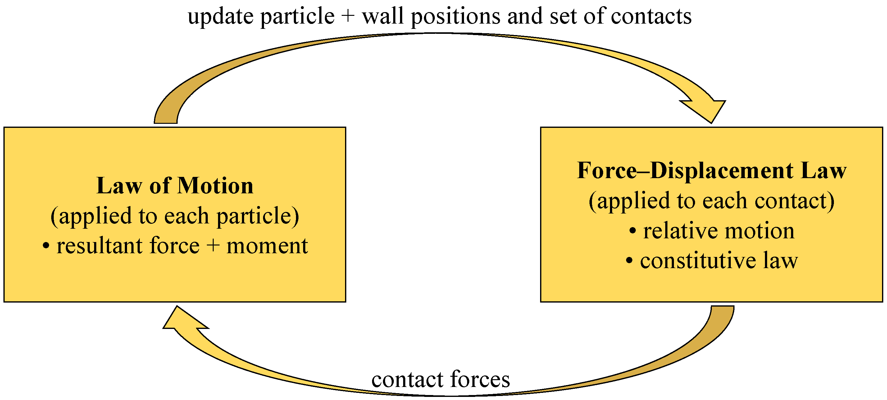
Particle flow discrete element is a discontinuous numerical calculation method, which is suitable for analyzing rock mechanics, soil mechanics, structural mechanics, material mechanics and fluid mechanics under quasi-static and dynamic conditions [82,83]. This method was first devised by Cundall and uses particle aggregates to represent objects [84]. Based on Newton’s second law and force–displacement law, the macroscopic constitutive behavior of objects is reflected by simulating the motion and interaction of particle elements [85]. The basic calculation principle is as follows: (1) according to the contact force between the particle units, the displacement, velocity and acceleration of each particle are calculated by Newton’s second law, and the position of the particle is updated. (2) According to the characteristics of particle displacement, the contact force between particle elements is updated by force–displacement law. Loop the above calculation until the model is broken or the set conditions are met, and the calculation ends (Figure 2) [86,87].
There are three basic contact models for the particle flow discrete element method: contact stiffness models (linear model and Hertz-Mindlin model), sliding model and bond model (contact bond model and parallel bond model) [88,89]. Among them, the contact stiffness model mainly reflects the relationship between the normal and shear contact forces between particles and the normal and shear relative displacement, which is often used to simulate the mechanical behavior of granular materials. The sliding model is an inherent characteristic of the contact particles. It has no normal tensile strength and allows the particles to slide within the shear strength range. The parallel bond model assumes that there are cementing materials between the particles that have a certain strength and allow certain deformation. The contact bonding model is defined as when bonding only occurs in a small range of contact points, while parallel bonding occurs in a limited range of circles or squares between contact particles. Contact bonding only transfers force, while parallel bonding transfers both force and moment [85]. The bond model can only be the bond between particles, and the bond model cannot be used between particles and walls. Two types of contact can simultaneously exist. The biggest difference between the contact bond model and the parallel bond model is that the two particles can rotate relative to one another after being connected by the contact bond model, while the two particles connected by the parallel bond model cannot rotate in this way. In this study, a parallel bond model was used to simulate shale samples (Figure 3).

2.2. Basic Assumption

To simplify the analysis, the following assumptions are made in the simulation:
  • The bedding of shale samples is of equal thickness, and there is no natural fracture.
  • Since the interaction between the drill bit and the rock can be regarded as the sum of the interaction between all the cutters on the drill bit and the rock, this paper focuses on a single cutter and simulates the cutting effect of a single PDC cutter on shale.
  • The influences of ground stress, temperature and hydrostatic pressure on rock mass are not considered.
  • In this paper, it is assumed that the drill bit moves along the center line of the wellbore with uniform rotational speed and uniform drilling speed without eccentricity; the drilling speed of drill bit and rotational speed of cutter are constant.
  • The actual movement form of cutters at the bottom of the well is spiral. In this paper, the movement of cutters is simplified as plane movement.
  • Due to the general view of predecessors, the cutting action of the blunt tooth (wear) tool or the traction drill is divided into two processes: (a) the pure cutting action in front of the cutting surface; (b) Friction processes across the wear surface [90,91,92,93,94]. This paper assumes that the drill cutter is sharp and only needs to consider the pure cutting force, without considering friction.
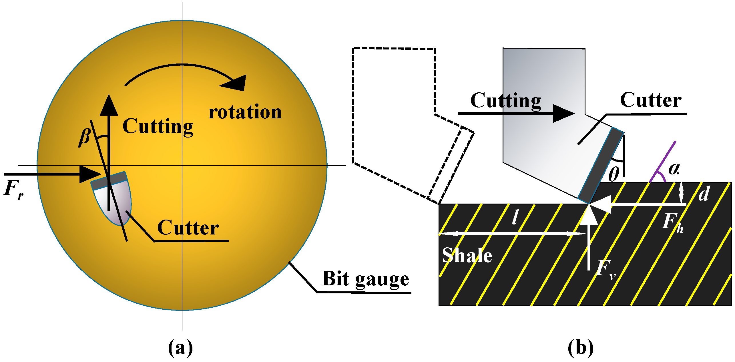
In the process of cutting rock, the reaction force of a PDC cutter can be divided into three parts: axial force Fv, tangential force Fh, and lateral force Fr (Fr is not considered in two-dimensional simulation). The tangential force is opposite to the movement direction of the cutter, and the axial force is perpendicular to the tangential force. The interaction model of a PDC cutter and rock mass is established as shown in Figure 4, where θ is the back rake angle, d is the cutting depth, and l is the cutting displacement.

2.3. Establishment of Model of Cutter Cutting Shale

With reference to the PFC2D rock sample model of Liu et al. and Zhou et al., the model of cutter cutting shale is established [96,97]. A series of circular particles was used to construct discrete element specimens, and a shale specimen model with a size of 120 mm × 60 mm was constructed by expansion method [98]. The radius of the round particle was determined using a Gaussian distribution: the particle radius ratio is 1.6, and the minimum radius is 0.3 mm. The particle density is 2411 kg/m3, and the single sample contains a total of 13,206 particles. Particle bonding adopts a parallel bonding model [99]. The JSET model is used to simulate the bedding plane of the shale, and the FISH function is used to eliminate the suspended particles. The micromechanical parameters of the sample when Yang et al. conducts the discrete element numerical test of shale Brazilian fracturing are selected as the micromechanical parameters of the shale sample in this paper; see Table 1 and Table 2 [100].
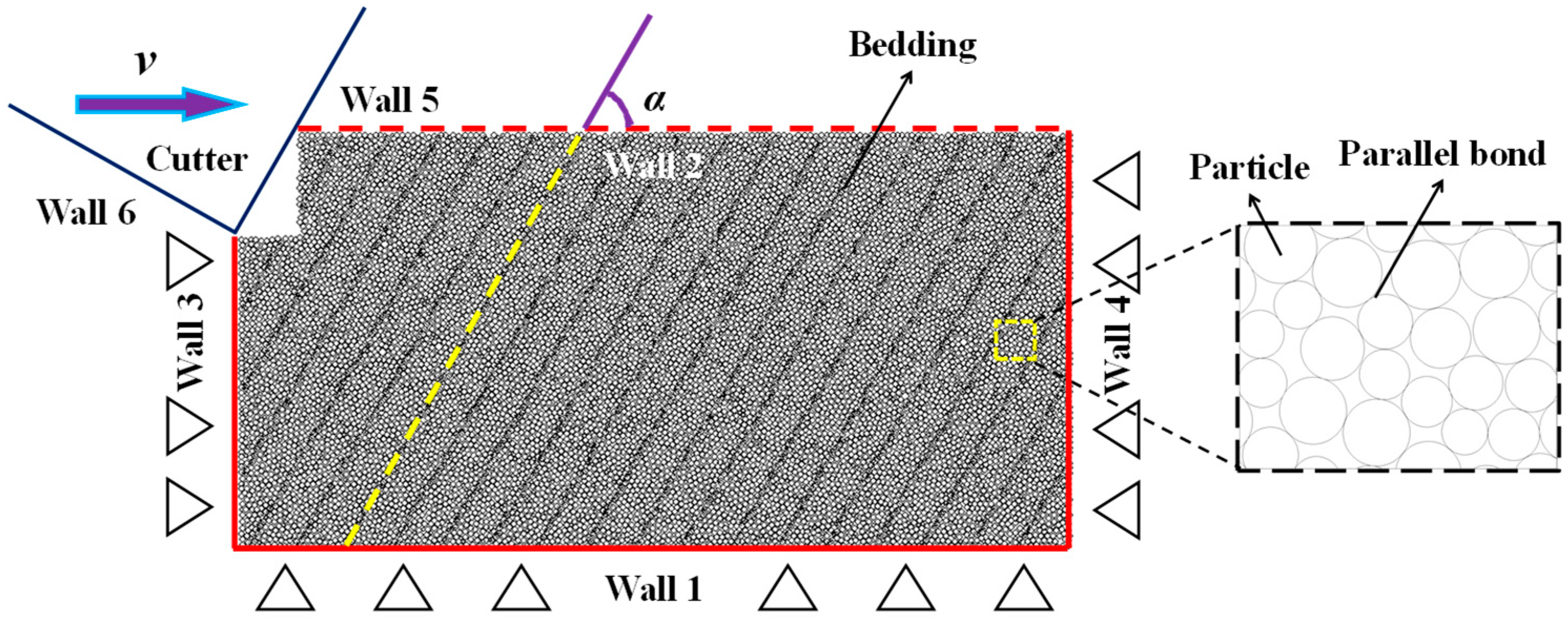
According to the test method of Lv et al., four frictionless rigid walls are defined to form a rectangle with a size of 120 mm × 60 mm, and particles with a given radius are randomly generated in this area [101]. After the particles generated, delete the 2# wall, with 1#, 3#, 4# wall limit rectangular specimens located at the bottom and on the left and right, respectively. The friction coefficient of the wall is set to 0, and the normal stiffness is set to 5 × 10⁴ GPa. During the test, the three walls remain fixed; the speed is constant at 0. Next, 5# and 6# walls perpendicular to each other and intersecting at one point are set to simulate cutter. The normal stiffness and shear stiffness of the two walls are set to 5 × 10⁶ GPa, and the friction coefficient is 0.5. The simulated back angle of the cutter is 30°. Since the model is built on a two-dimensional plane, regardless of the diameter of the cutter and the size of the roll angle in the cutting plane, the sharp angle formed by the intersection of the two walls represents the tip of the cutter.
In order to simulate the different depths of the cutter’s starting position (which remains unchanged), and from the beginning of cutting contact with the rock, we set a groove in the shale sample near the cutter, and the depth of the groove with the cutter position changes and is constantly adjusted so that the displacement of cutter is equal to the effective cutting displacement. The cutter moves horizontally on the specimen at a constant speed v and a fixed cutting depth d. The horizontal displacement of the cutting and the forces on the cutter in the vertical and horizontal directions are recorded during the cutting process. The horizontal displacement of the 5# wall is recorded as cutting displacement of cutter; the absolute value of the resultant force of the vertical unbalanced force of the 5# and 6# walls is recorded as the vertical force of the cutter. The absolute value of the resultant force of the horizontal unbalanced force of the 5# and 6# walls is recorded as the horizontal force of the cutter. The numerical samples and loading boundary conditions are shown in Figure 5.
The same initial horizontal shear rate v is determined for the 5# and 6# walls. When the 5# and 6# walls contact the shale sample, the cutting load is applied to the sample. The rates of the 1#, 3#, and 4# walls in the horizontal direction are set to 0 throughout the test.

2.4. Numerical Test Scheme

In this study, the cutter of a PDC bit, with a diameter of 215 mm, a drilling speed of 10 m/h, and a rotation speed of 50~90 r/min, was simulated. According to the rotation speed of the bit, the cutting speed of the cutter was 0.6~1.0 m/s. According to the simulated drill bit size, we used the PFC2D software to build a shale sample with a size of 120 mm × 60 mm. In order to improve the computational efficiency of the simulation, we expanded the cutting rate of the cutter on the original basis (0.6 m/s, 0.7 m/s, 0.8 m/s, 0.9 m/s, and 1 m/s) by 10 times (6 m/s, 7 m/s, 8 m/s, 9 m/s, and 10 m/s) so that the simulation test was efficiently carried out.
We considered the effects of different shale bedding dips (0°, 30°, 45°, 60°, and 90°), different shale bedding thicknesses (2 mm, 4 mm, 6 mm, 8 mm, and 10 mm), different cutting depths (5 mm, 10 mm, 15 mm, 20 mm, and 25 mm) and different horizontal cutting rates (6 m/s, 7 m/s, 8 m/s, 9 m/s, and 10 m/s) on the rock-breaking efficiency of the cutter. We analyzed the crack propagation and specimen fragmentation of shale under different factors using a control variable method and elucidated the mechanism of crack initiation, propagation and coalescence. Table 3 shows all simulated conditions.

3. Results

3.1. Effect of Bedding Dip

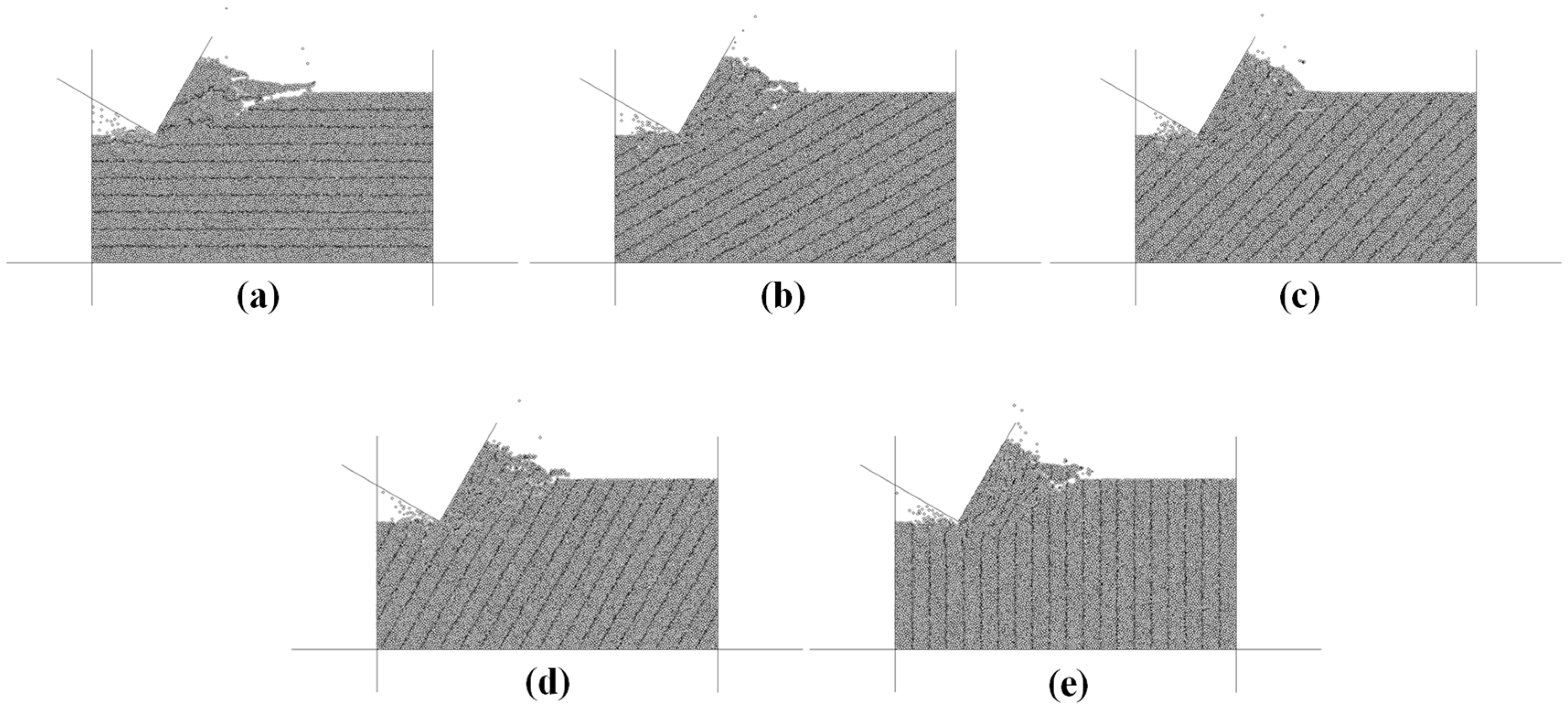
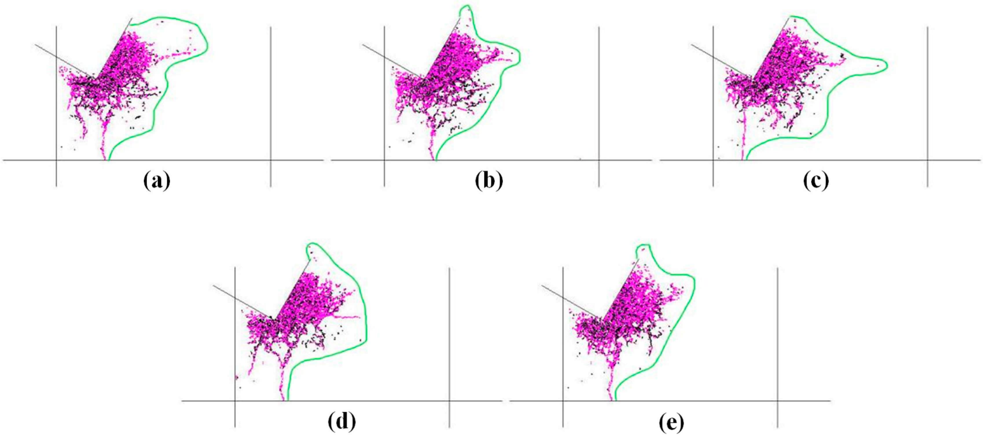
According to the simulation conditions shown in Table 3, we calculated the results of the effect of bedding dip. Figure 6 shows the cutting failure modes of specimens with different bedding dips. Figure 6 shows that the change in bedding dip has a certain influence on the cutting failure mode of shale. After cutting and crushing, particles and blocks are formed in the upper left corner of the sample, but the size of the blocks is different. Among them, the 0° specimen is cracked along the direction of the bedding plane by the cutting force, and the top bedding plane forms a large sample fragment under the cutting action. The rock fragments formed by 30° and 45° specimens under the action of cutting force are smaller and even become particles, and there is little damage along the bedding plane. The failure modes of 60° and 90° specimens lie somewhere in between. The above-mentioned sample damage shows that the angle between the cutting direction of the cutter and the normal direction of the bedding surface determines the cutting and crushing morphology of the sample to a certain extent. With a smaller angle, the force of the cutter on the bedding surface is closer to the vertical direction, and the volume of the sample crushing block is smaller. In general, the bedding plane dip of shale is different, and the range and shape of the deformation and failure of shale are different under the action of cutter cutting.
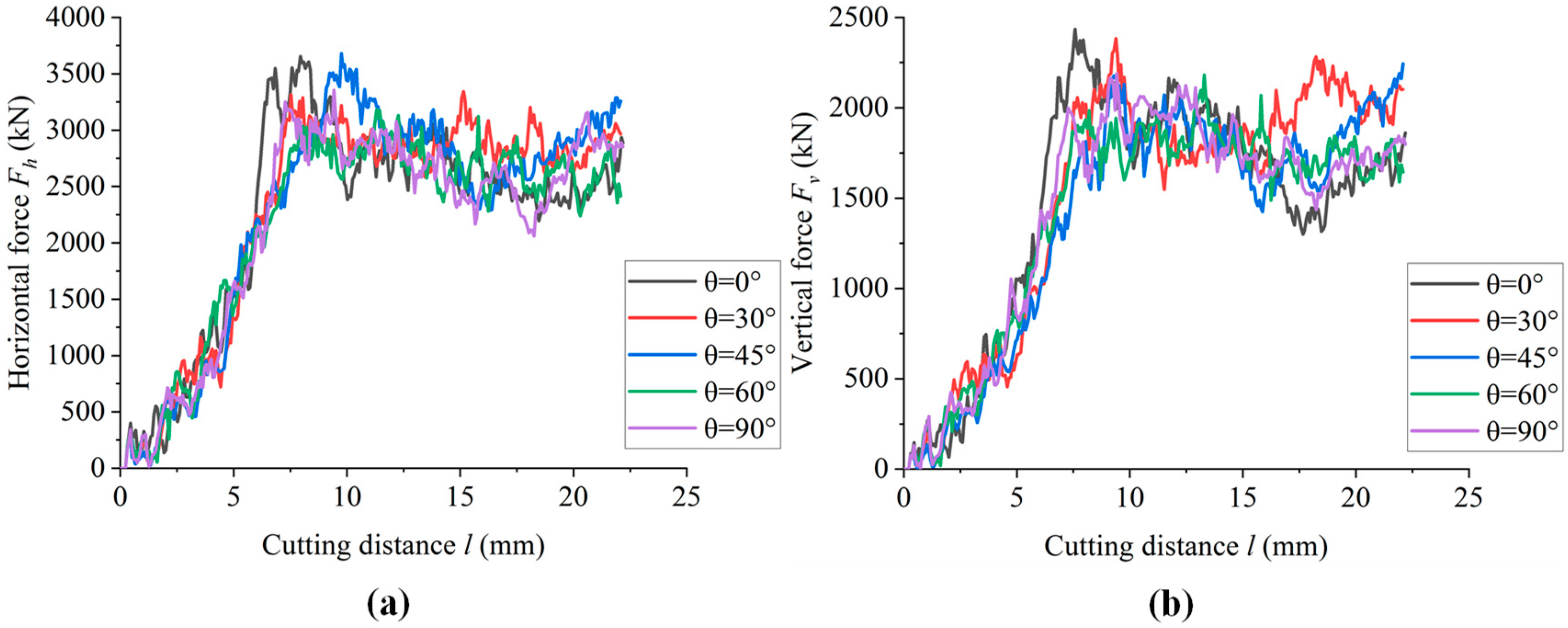
Figure 7 shows the simulated curves of horizontal cutting force and vertical cutting force with cutting distance for different bedding dips. Comparing Figure 7a and Figure 7b, it can be seen that the cutting force rapidly increases with the action of the cutters on the shale. After the sample is broken, the increase in cutting force fluctuates with the increase in cutting distance. The change trend of horizontal component force and vertical component force is essentially the same, and the horizontal component force is always greater than the vertical component force. Further observation shows that the average cutting force of 30° and 45° samples is larger than that of other samples, while the average cutting force of 60° and 90° samples is relatively small. This shows that the larger the inclination angle, the easier the sample is to break under cutting.
Figure 8 shows the crack distribution of specimens with different bedding plane dips. It can be seen from Figure 8 that the crack distribution of samples with different bedding dips has certain differences, and the volume of crack distribution first increases and then decreases with the change in inclination angle. The crack propagation area of 45° specimen is the largest and that of 90° specimen is the smallest. From the crack distribution area, the typical cutting splitting phenomenon of brittle rock mass can be determined to a certain extent.
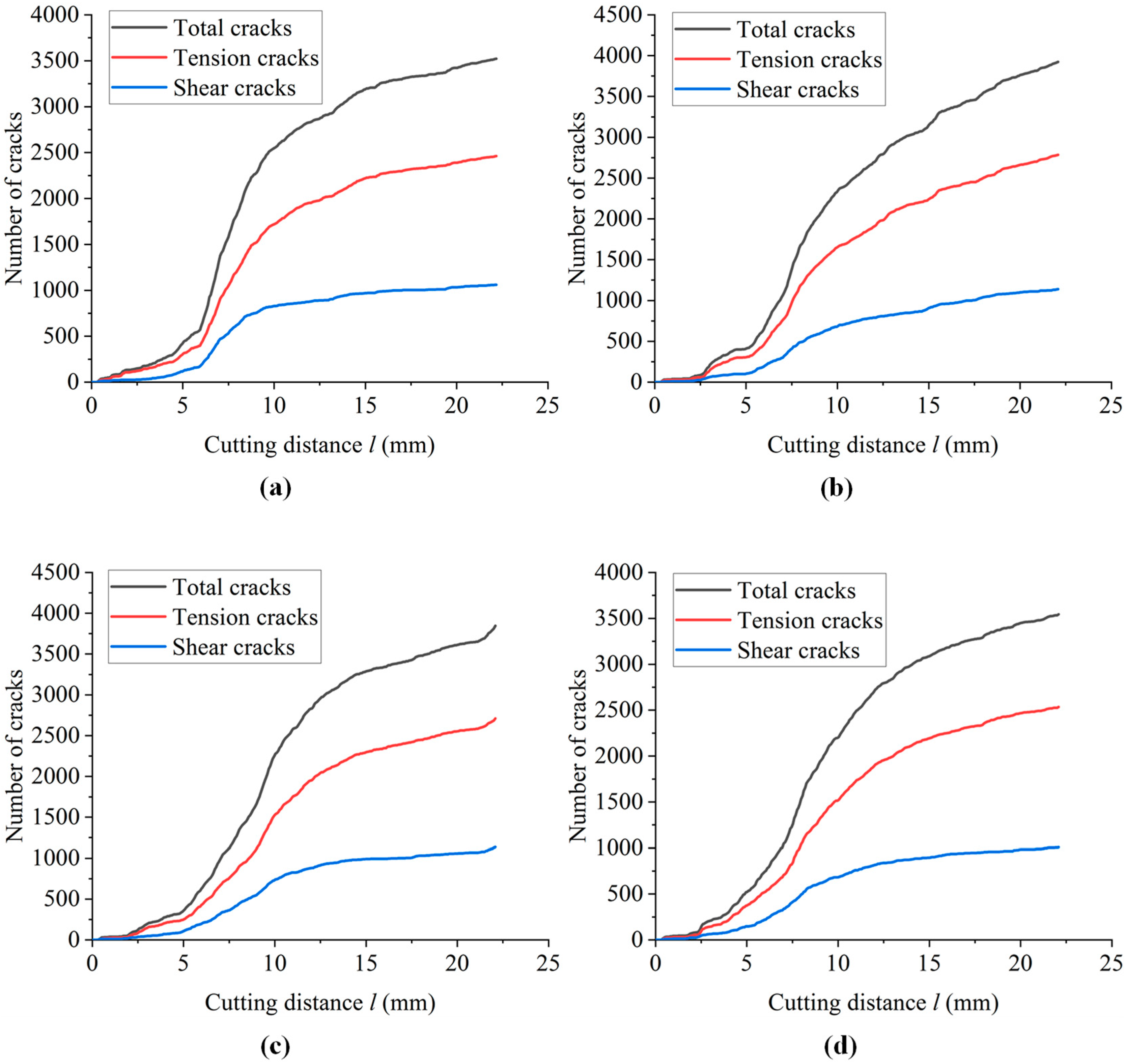
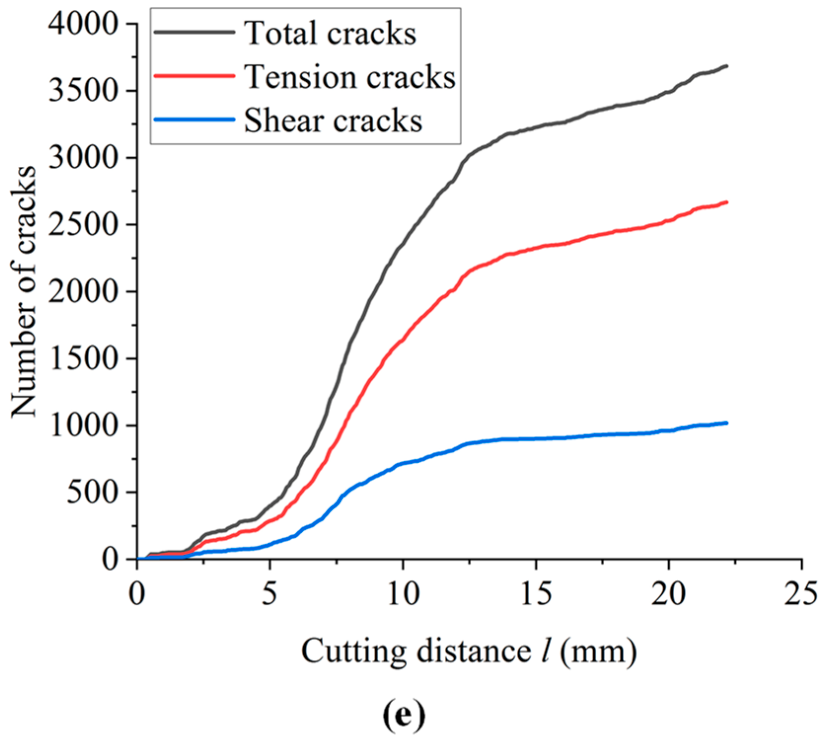
Figure 9 reflects the crack propagation law in the simulation process of samples with different inclination angles. It can be seen from the crack growth curve in Figure 9 that when the cutting distance is less than 5 mm, the crack number growth rate is very small. When the cutting distance is between 5 and 10 mm, the number of cracks rapidly increases with cutting distance. The crack growth of the 0° specimen is the fastest, and when the cutting distance exceeds 10 mm, the change in the crack growth curve tends to be gradual. When the cutters penetrate more than 10 mm in shale, the propagation of the fracture zone and crack needs more drilling tool energy; therefore, the curve of crack number vs. cutting distance is relatively flat.

3.2. Effect of Bedding Thickness

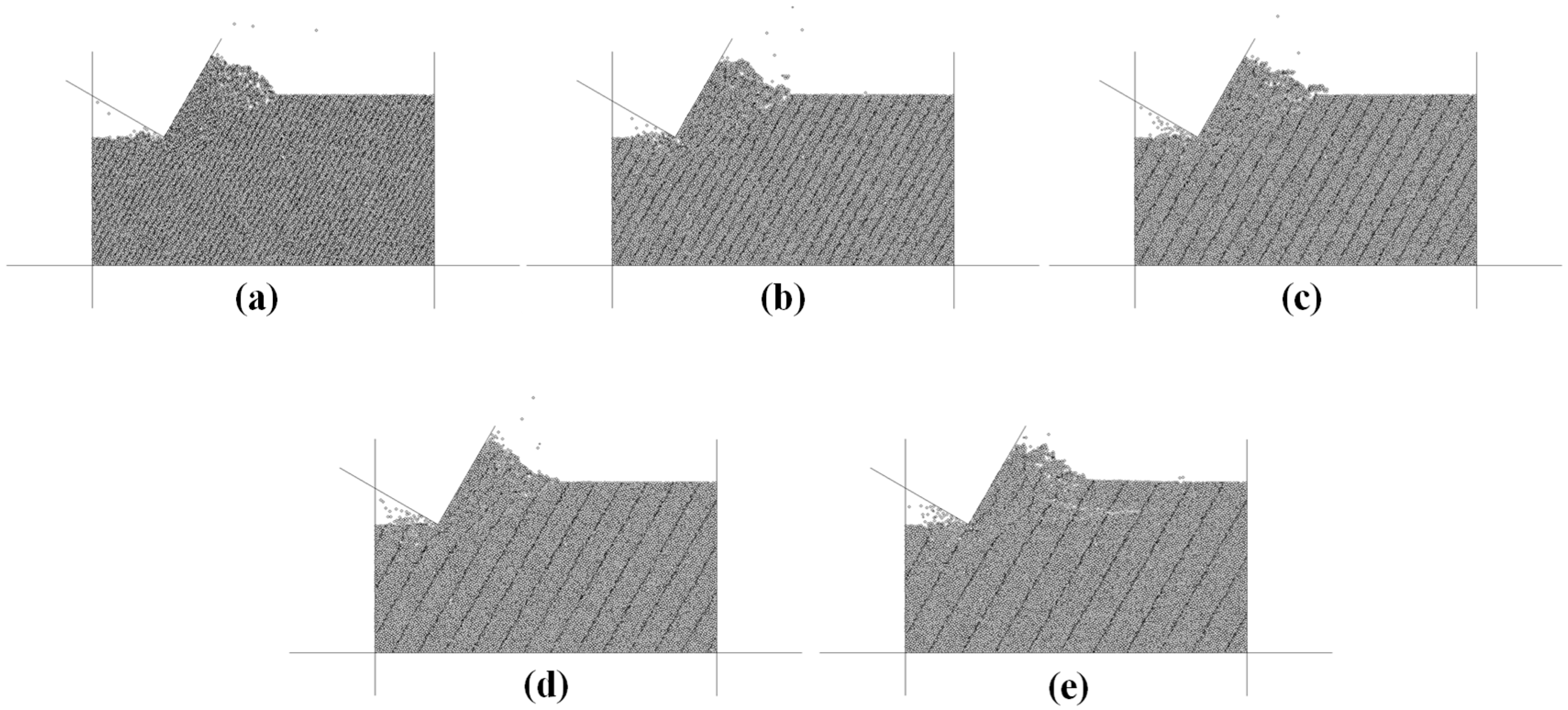
According to the simulation conditions shown in Table 3, we calculated the results of the influence of bedding thickness. Figure 10 shows the cutting failure of shale with different bedding thicknesses. It can be observed that different samples form a fracture surface extending from the bottom of the cutter to the bottom of the sample under the action of the cutter. The smaller the thickness of the bedding plane, the more broken cutting particles are produced. For example, the sample with a thickness of 2 mm of the bedding plane produces a large number of broken particles under the cutting action, while the sample with a thickness of 10 mm of the bedding plane forms a larger volume of cutting fragments. With the increase in the thickness of the bedding plane, the extension of the fracture surface formed in the horizontal direction of the sample is longer. The specimen with a bedding thickness of 10 mm produces a fracture surface in the fracture zone extending close to the free surface. Under the action of cutters, the shale fragments are pushed up, which is manifested as a vertical volume expansion of the sample. With the increase in shale bedding thickness, the phenomenon of volume expansion becomes increasingly significant, and the size of cutting fragments becomes larger. Evidently, the thickness of bedding plane has a certain influence on the cutting failure mode of shale.
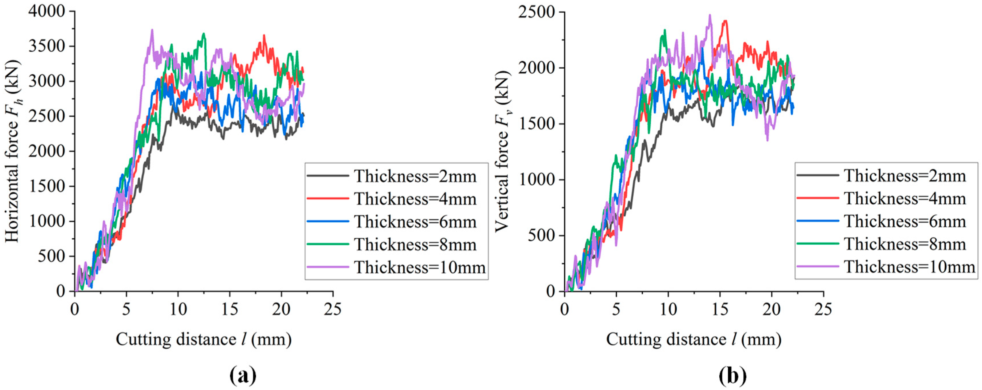
Figure 11 shows the distribution of the horizontal and vertical components of different bedding thicknesses with cutting distance. When comparing Figure 11a and Figure 11b, it can be seen that the horizontal cutting force of the shale is much larger than the vertical cutting force, and the horizontal component force and the vertical component force rapidly increase with the increasing number of cutters. After the formation of a large fracture zone, the cutting force begins to flatten. Compared with the horizontal component, the vertical component distribution is more uniform, and the coincidence degree of each sample curve is higher. This is determined by the angle between the predetermined cutting direction and the bedding direction. According to the relationship between cutting force and cutting distance, different sample curves also have some differences. The horizontal and vertical forces of the cutters alternate; the overall trend is an increase followed by a decrease, and then another increase. The horizontal component force and vertical component force of the sample with a thickness of 2 mm are lower than other samples.
Figure 12 shows the crack distribution of specimens with different bedding thicknesses. According to Figure 12, it can be observed that, with the increase in the thickness of the bedding surface, the crack length in the horizontal direction also increases. The distribution of tensile cracks is significantly affected by the bedding surface, and the proportion of tensile cracks in the cutting area of the cutter decreases. This shows that the specimens with larger bedding thicknesses have more significant cutting splitting phenomenon, and the tensile cracks are more likely to develop on the weak surface. With the increase in bedding thickness, the density of weak surface decreases; therefore, the distribution of tensile cracks along the weak surface is relatively small.
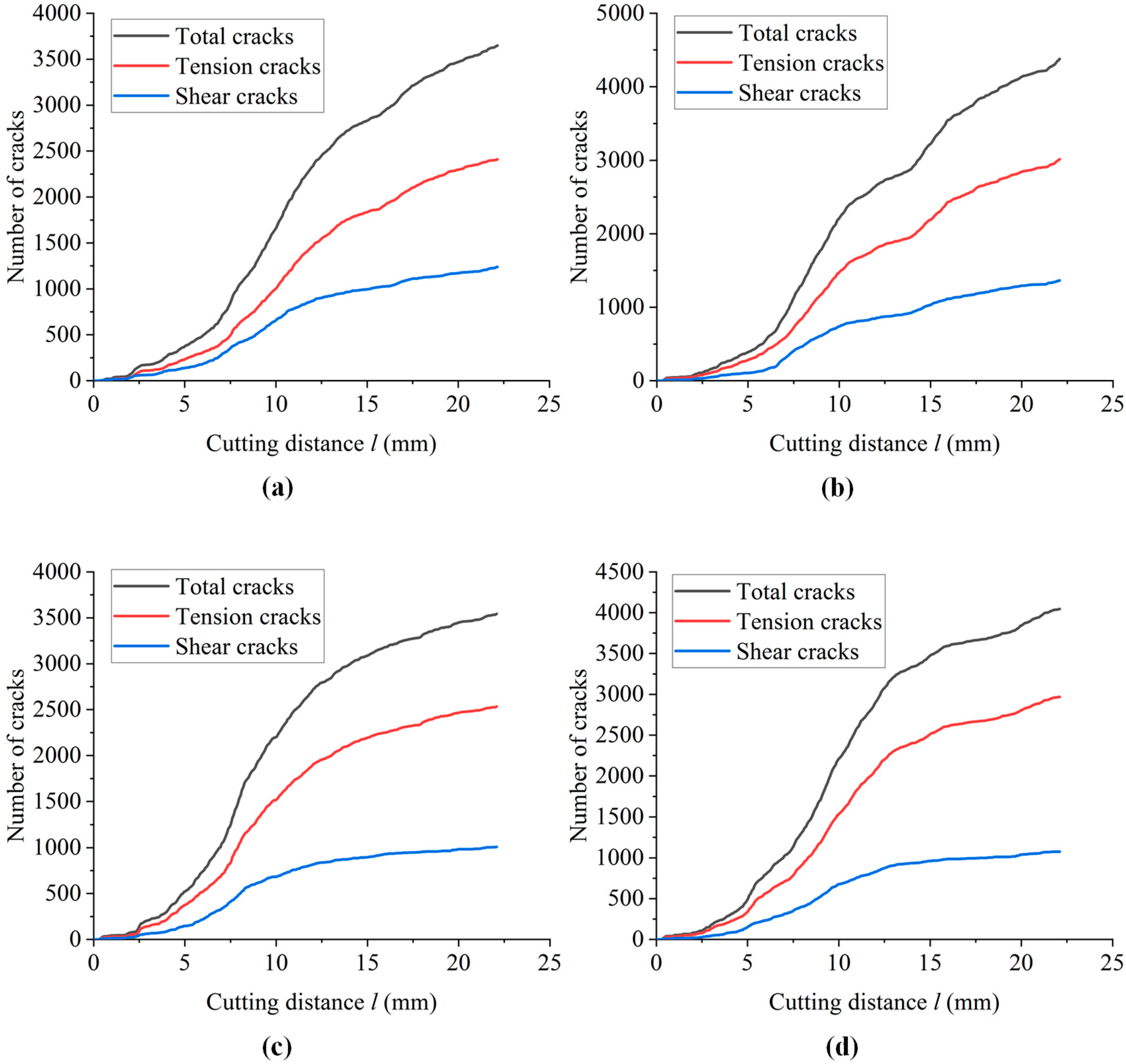
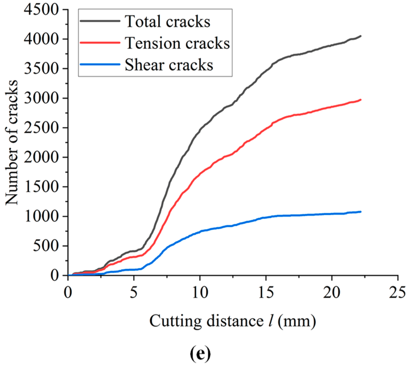
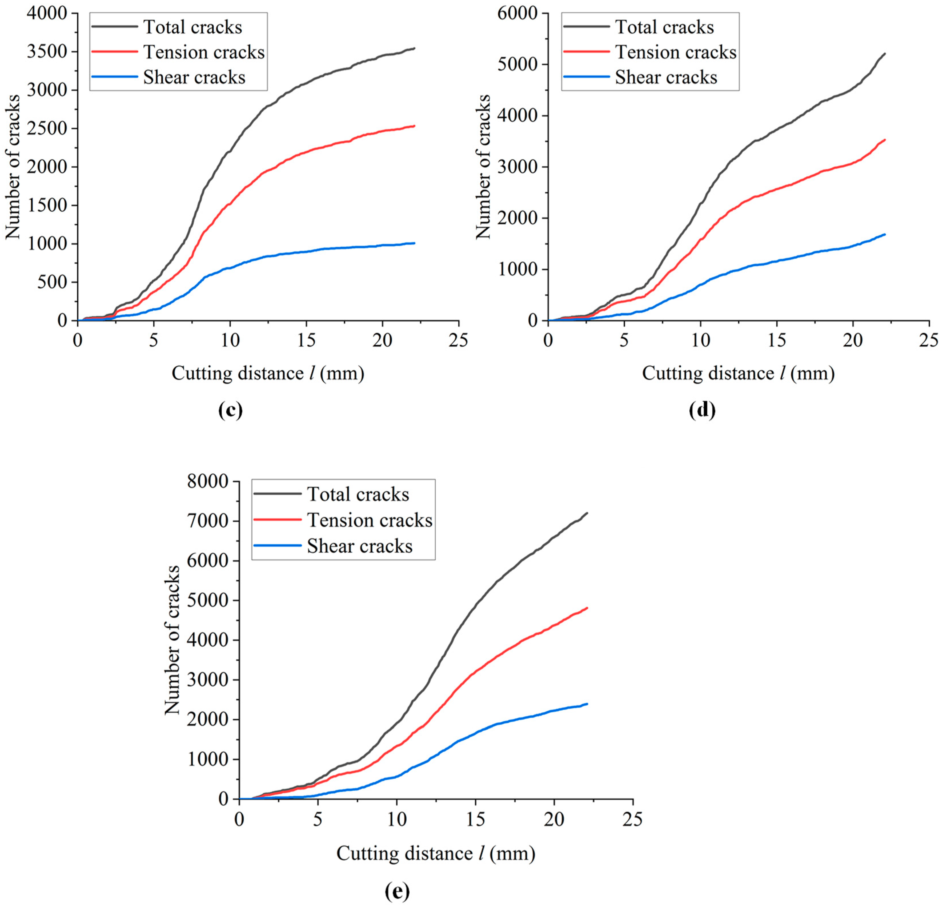
Figure 13 shows the relationship between the number of cracks vs. the cutting distance of shale samples with different bedding plane thicknesses. According to the crack number vs. cutting distance curve shown in Figure 13, when the drill bit horizontally cuts 5~10 mm into the shale, the number of cracks rapidly increases with the increase in cutting distance. When the horizontal cutting distance exceeds 10 mm, the increase in the number of cracks tends to be flat, indicating that when the drill bit cuts deeper than 10 mm, the fracture zone and crack propagation requires more drilling energy.

3.3. Effect of Cutting Depth

According to the simulation conditions shown in Table 3, we calculated the effect of cutting depth. Figure 14 shows the failure modes of samples with different cutting depths. As can be seen from Figure 14, as the cutting depth increases, the volume of the fracture zone increases, and the cutting fracture zone at the front end of the cutter expands horizontally toward the inside of the sample. When the cutting depth is 25 mm, the horizontal fracture zone extends to the free surface. At the same time, it can also be found that the long cracks produced by the sample first increase and then decrease with the increase in cutting depth. When the cutting depth exceeds 15 mm, an increasing number of secondary microcracks develop along the existing long cracks, and the long cracks do not extend. This is because the greater the cutting depth of the cutter, the more broken particles the sample produces after the same cutting distance. These particles accumulate in large quantities at the front end of the cutter, directly contact with the surface of the cutter, and transfer the cutting force of the cutter to the lower sample. The sample is no longer directly affected by the cutter, but is squeezed by the broken particles to form an increasing number of microcracks. Due to the increase in the overall cutting force, the lower right corner of the sample also has squeezed microcracks due to the increase in the reaction force. It can be seen that the cutting depth has a significant effect on the rock-breaking efficiency. We have reason to speculate that there may be an optimal range of cutting depths. When the cutting depth increases to a certain extent, it is not conducive to improving the rock-breaking efficiency.
Figure 15 shows the relationship between the horizontal and vertical components vs. cutting distance under different cutting depths. It can be seen from Figure 15a and Figure 15b that the horizontal force on the cutter is greater than the vertical force. Comparing the curves of different samples, it was found that the effect of cutting depth on cutting force is very significant. With the increase in cutting depth, the cutting force significantly increases. For samples with a large cutting depth, such as 20 mm and 25 mm, the displacement time taken to reach the peak cutting force is also large. At smaller cutting depths of the sample, such as 10 mm and 15 mm, when the drill cutting distance increases, so does the first peak cutting force. At a 5 mm depth of the sample, in the whole cutting process, the cutting force had a slow fluctuation. This is because the greater the cutting depth, the greater the displacement required to form the fracture zone in the sample.
Figure 16 shows the crack distribution of samples with different cutting depths. The simulation results shown in Figure 16 reveal that, with the increase in cutting depth, more cracks are produced around the cutter, and the volume of the crack propagation area also increases. When the cutting depth is further increased, the directional propagation of long cracks is no longer increases. Due to the extrusion of the cutter, a large number of microcracks begin to form in the sample, and some microcracks may extend to the free surface of the sample. With the further increase in the extrusion effect, the right lower corner area of the sample under larger cutting force begins to form microcracks.
Figure 17 shows the relationship between crack number and the cutting distance of samples with different cutting depths. Figure 17 shows that the crack growth curves of different cutting depths are significantly different. The number of cracks in the samples at 10 mm and 20 mm depths have two rapid growth stages, and the curve of the sample at a 5 mm depth shows a fluctuating upward trend. Overall, the smaller the cutting depth, the number of cracks to achieve rapid growth of the required cutting distance is smaller, on the contrary, in the larger displacement at the time of rapid growth. This is because the cutter with different cutting depths begins to cut from the left side of the sample. The tip of cutter with a smaller cutting depth reaches the maximum contact area between the cutter and the sample after a smaller displacement, and then the cracks expand in all directions, causing them to grow rapidly. In contrast, with a larger cutting depth of the sample, the cutter surface and sample need to experience a larger displacement to reach the maximum contact area, so the rapid growth of the crack time is relatively delayed.

3.4. Effect of Cutting Rate

According to the simulation conditions shown in Table 3, we calculated the effect of cutting rate. Figure 18 shows the failure characteristics of shale samples with different cutting rates. It can be seen from Figure 18 that, under the same displacement conditions, the cutting rate of the drill tooth will affect the size of the cutting debris. When the cutting rate is small, the fragments of shale are relatively large, and less particles are produced by cutting. With the increase in cutting rate, the size of the cutting fragments produced by shale gradually decreases, while the broken particles at the front end of the cutter gradually increase. This shows that the cutting rate has a certain impact on rock-breaking efficiency.
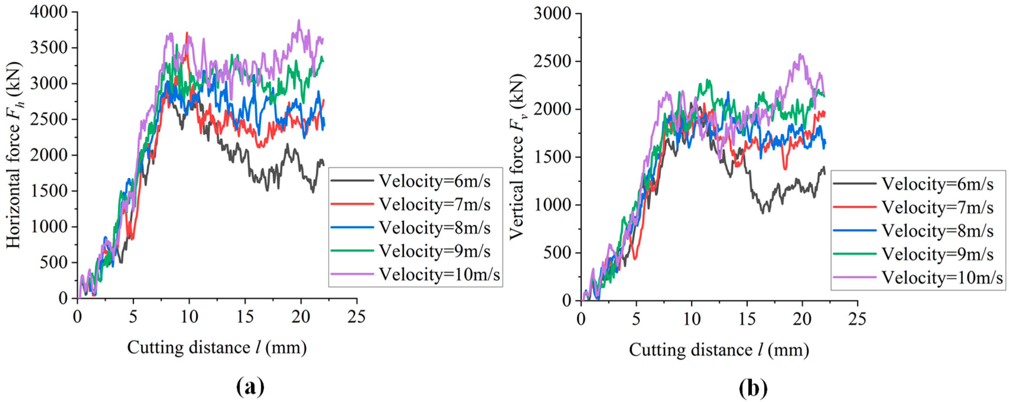
Figure 19 shows the relationship between cutting force and cutting distance at different cutting rates. According to the simulation results shown in Figure 19, when the cutter displacement is less than 7 mm, the effect of cutting rate on cutting force is not significant. Under a relatively small cutting distance, the variation in cutting force corresponding to different cutting rates is very small. When the cutting distance exceeds 7 mm, the effect of rate on shale cutting can be observed. With the increase in cutting rate, the horizontal cutting force and vertical cutting force significantly increase, the cutting force of the sample with a cutting rate of 6 m/s is significantly smaller than those of the other samples, and gradually decreases after reaching the peak. The cutting force of the sample with a cutting rate of 10 m/s is larger than that of other samples. With the further increase in cutting distance, the change in cutting force fluctuates.
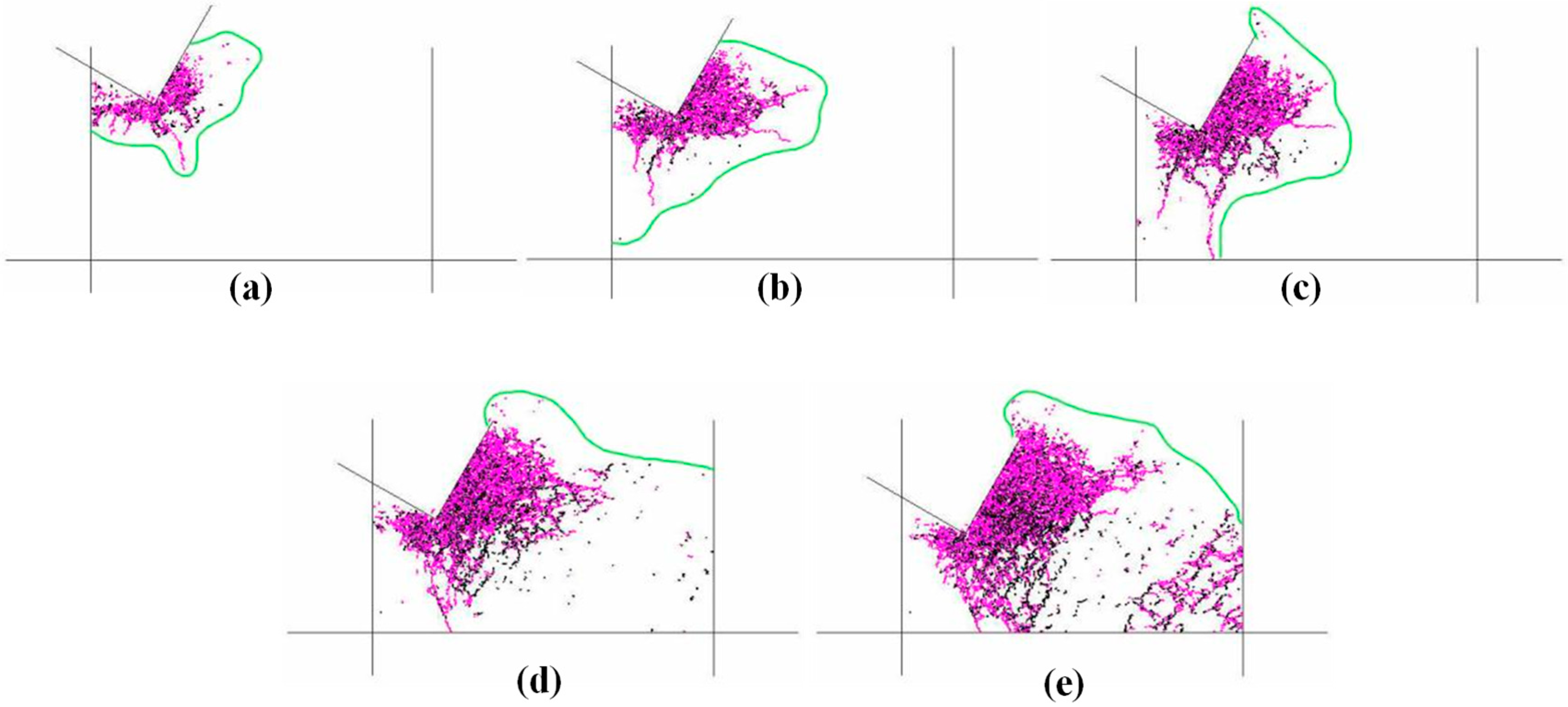
Figure 20 shows the effect of cutting rate on the crack distribution of the sample; with the increase in cutting rate, the crack propagation area continuously increases. When the cutting rate further increases, the crack propagation area no longer increases. It is reasonable to speculate that this phenomenon is mainly because as the cutting rate increases, the cutting force also increases relatively, and the crack gap becomes smaller under the action of extrusion, so that the crack propagation area no longer increases.
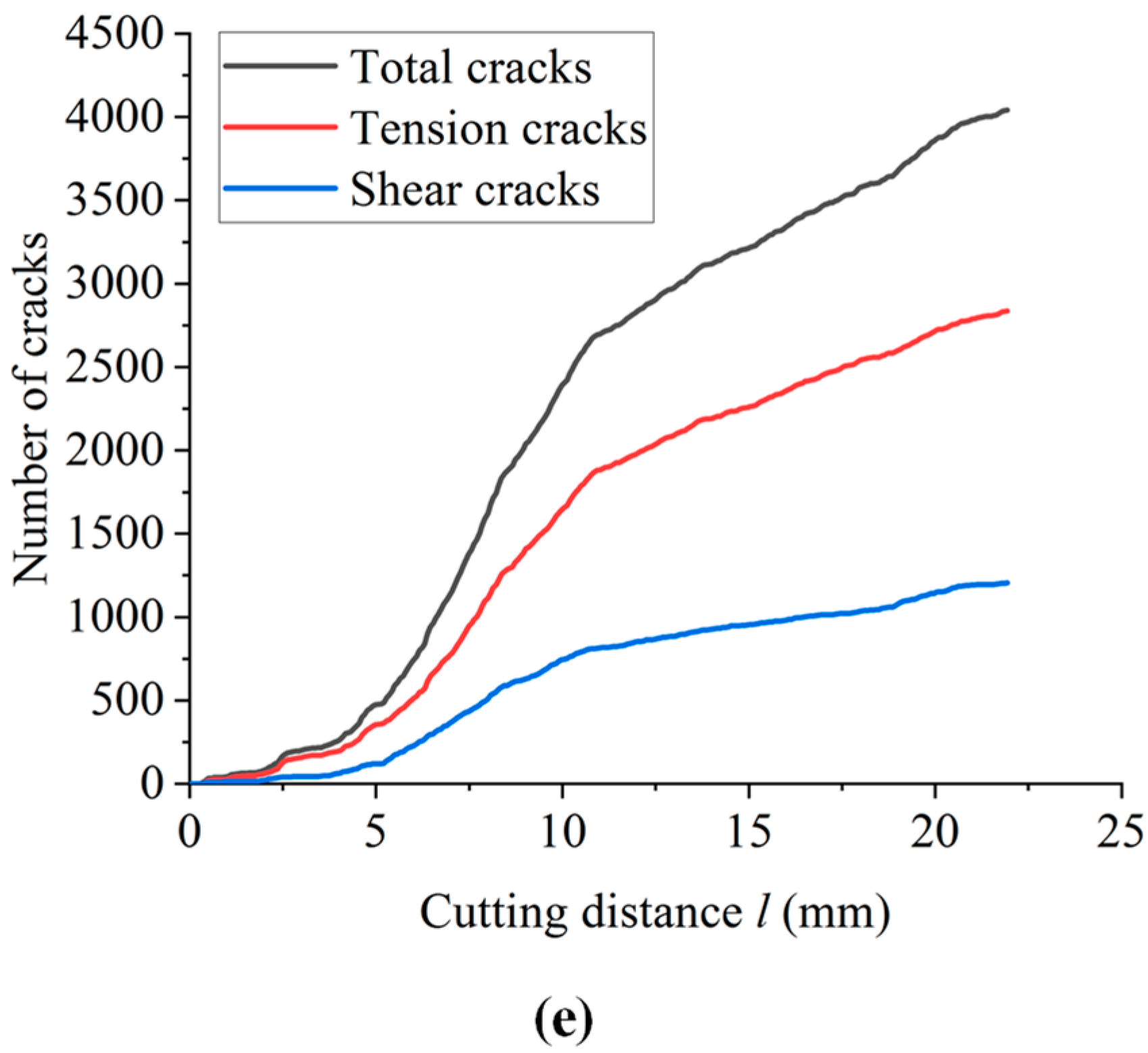
Figure 21 shows the curves of crack number versus the cutting displacement for specimens with different cutting rates. According to the curve of the number of cracks vs. cutting distance of cutter shown in Figure 21, it can be considered that when the cutting distance is less than 5 mm, the effect of the cutting rate on the number of cracks is not significant. When the cutting distance is greater than 5 mm, the curves of different samples show some differences. It can be observed that the cutting rate has a certain effect on the number of cracks.

4. Discussion

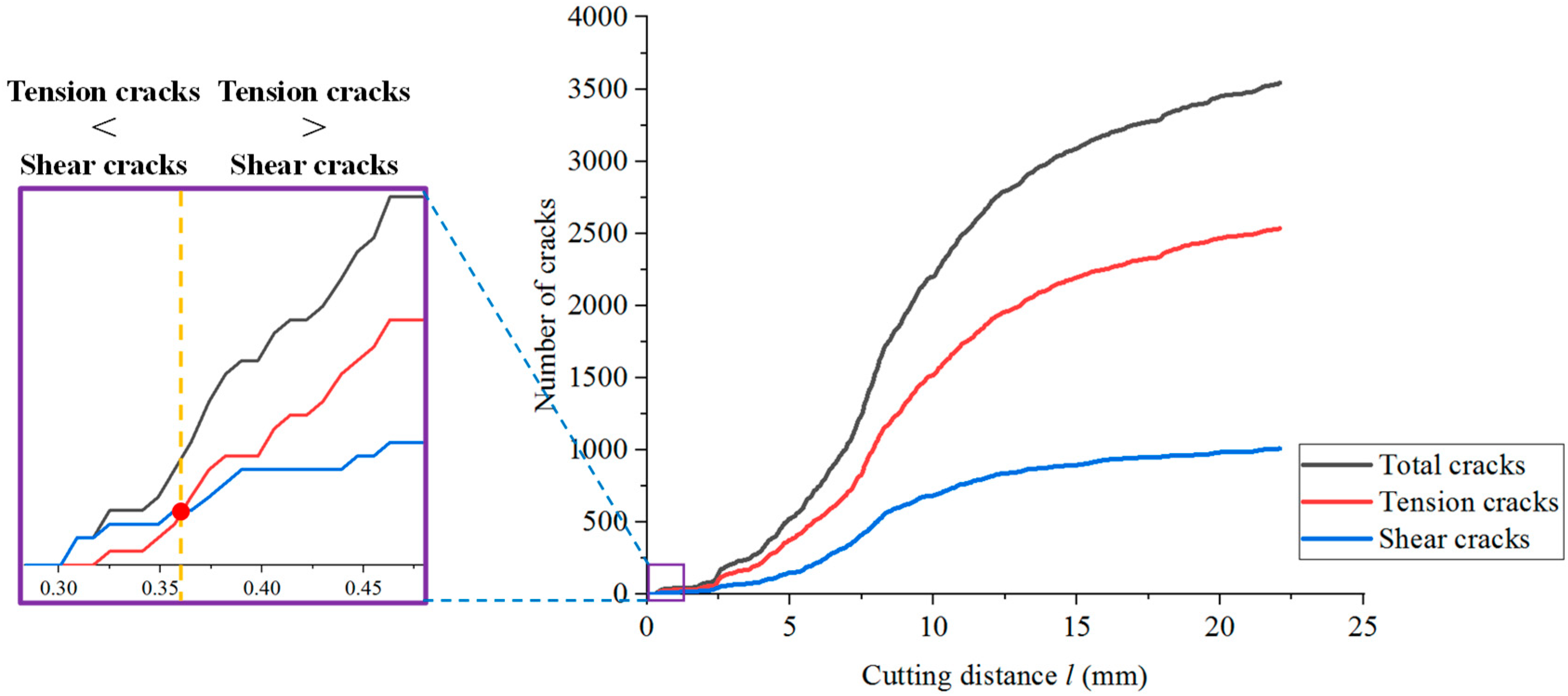
On the basis of the previous research results, the propagation of microcracks is further discussed. Under the influence of different factors, the change in cracks generated by the sample with a cutting displacement is shown in Figure 22. It can be seen from Figure 22 that, under the cutting of drill teeth, the number of tensile cracks and shear cracks of shale samples with different bedding angles and thicknesses have an S-shaped growth trend at different cutting rates. Take the bedding dip angle of 60° as an example, as shown in Figure 23. At the beginning of cutting, shear cracks first develop in the sample, and then tensile cracks occur. The number of shear cracks is more than that of tensile cracks. With the increase in cutting displacement, the number of tension cracks soon exceeds the number of shear cracks. After that, the number of shear cracks and tension cracks rapidly increases, and the growth rate of tension cracks is higher than that of shear cracks. With the further increase in cutting displacement, the growth rates of shear cracks and tension cracks tends to reduce.
It is worth noting that the control effect of cutting depth on crack growth is significantly greater than the other three factors. Especially when the cutting depth is 5 mm, the crack growth curve of the sample is clearly different from that of the sample with other cutting depth conditions, and the crack growth has neither three S-shaped change stages nor clear signs of flatness. This is potentially because, when the cutting depth is small, the vertical cutting area of the sample under the cutting action of the drill teeth is relatively small, and only the horizontal cutting area continues to increase; therefore, it is difficult for the sample to quickly generate and expand a large number of microcracks. With the increase in cutting displacement, microcracks can only be generated and expanded at a low rate.
We further discuss the change in the proportion of tension cracks in the sample with the cutting displacement under different influence factors, as shown in Figure 24. The proportion of tension cracks is higher than that of shear cracks soon after they begin to develop. With the increase in cutting displacement, the proportion of tension cracks reached a peak value when the cutting displacement was 4~5 mm. After a short decline, the proportion of tension cracks gradually became stable. In summary, under the cutting action of drill teeth, the destruction of shale was not accomplished in one stroke, but experienced the initiation and expansion of microcracks, as well as the connection between microcracks.
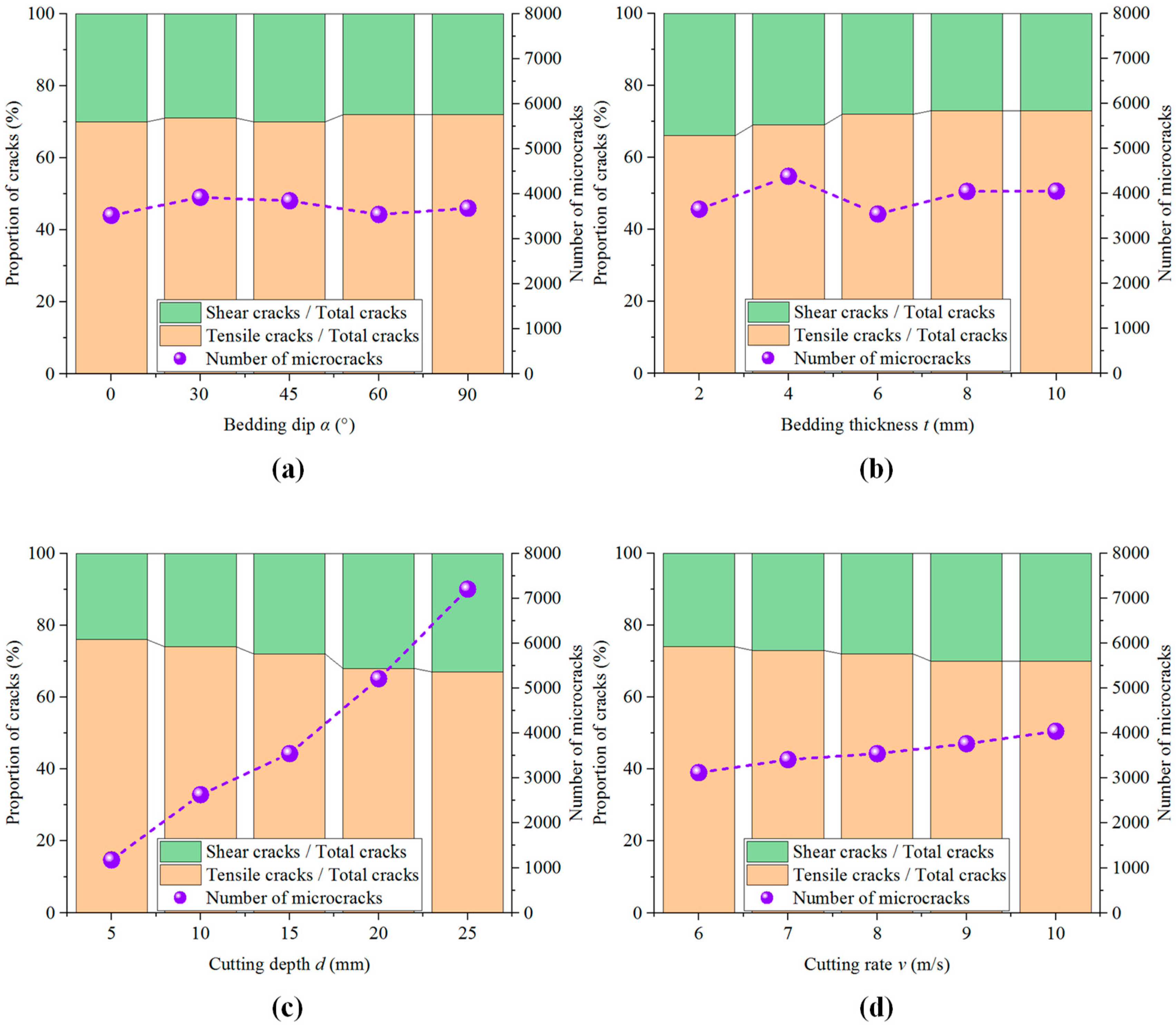
When the sample reaches the same cutting displacement, 22.1 mm, the percentage of tensile cracks and shear cracks and the number of total cracks change with different levels of various factors are as shown in Figure 25. This figure shows that, when the bedding angle and bedding thickness increase, the proportion of tension cracks shows a slight increasing trend, and the total number of cracks in both fluctuates. When the bedding angle is 30° and the bedding thickness is 4 mm, the total number of cracks reaches the maximum, respectively. When the cutting depth and cutting rate increase, the percentage of tensile cracks slightly decreases, and the total number of cracks in both cases linearly increases. When the cutting depth is 25 mm, and the cutting speed is 10 m/s, the total number of cracks reaches the maximum, respectively. In conclusion, when the bedding angle is small, the bedding thickness is small, the cutting depth is large, and the cutting speed is large, the specimen is more likely to be damaged under the cutting action. However, in practical projects, the life of the bit should be considered and the drilling parameters should be reasonably set.
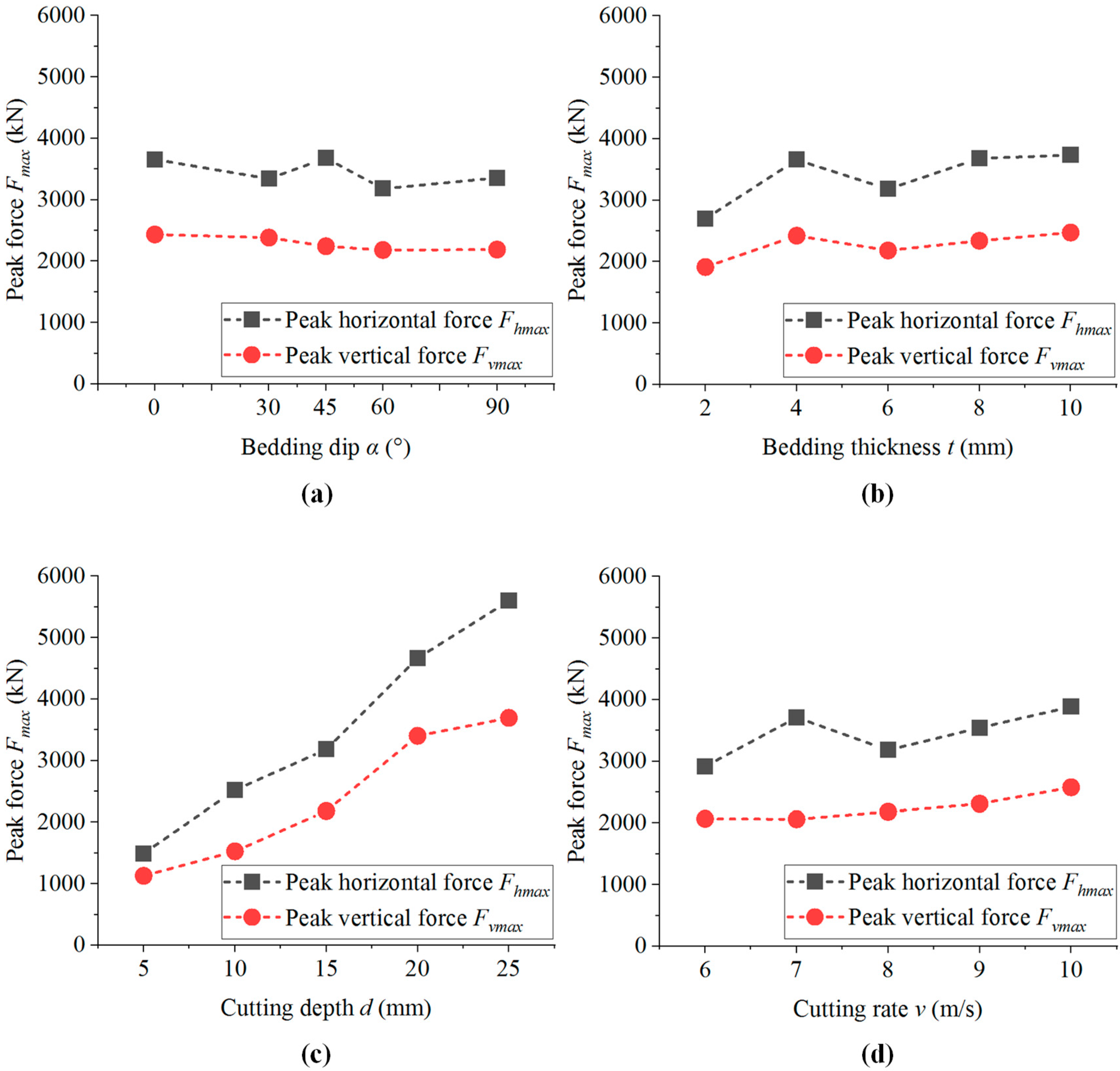
On the basis of the previous research, the change in cutting force with different levels of various factors in the sample cutting process is further discussed, as shown in Figure 26. It can be seen from Figure 26 that the peak horizontal cutting force fluctuates and decreases with the increase in bedding angle, fluctuates and increases with the increase in bedding thickness and cutting speed, and increases approximately linearly with the increase in cutting depth. The peak vertical cutting force decreases with the increase in bedding angle, fluctuates with the increase in bedding thickness, and increases with the increase in cutting depth and cutting speed. In general, the peak horizontal cutting force and peak vertical cutting force have similar trends with different levels of various factors, and the peak horizontal cutting force is always greater than the peak vertical cutting force. Compared with the other three factors, the influence of cutting depth on the peak cutting force is more significant.
The drilling efficiency is generally evaluated by the value of MSE [34]. Referring to the model of [63], we assume that the cutter of the drill bit is sharp and only consider the horizontal force Fh of the cutting rock mass. Therefore, the mechanical specific energy MSE is:
M S E = W V = 0 l F h i d l t l d
where MSE is the mechanical specific energy, J/m3; W is the work consumed by broken rock mass, J or N·m; V represents the volume of broken rock mass, m3; Fhi is the horizontal component of cutting force, N; l is the cutting displacement, mm; t is the cutting thickness, mm; d is the cutting depth, mm.
For different influencing factors, the work W is calculated by integrating the horizontal cutting vs. the force-cutting displacement curve recorded by the above simulation. In PFC2D, the thickness of the sample is 1 m by default, so the thickness t is 1000 mm. The MSE can be obtained from W/V: From Figure 27a, it can be found that the MSE increases first and then decreases with the increase in bedding dip, eventually reaching the lowest rock-breaking efficiency. According to Figure 27b, it can be concluded that the MSE increases with the increase in bedding thickness, and generally adheres to the law of increasing fluctuation. It can be seen from Figure 27c that the MSE decreases with the increase in cutting depth. Figure 27d shows that the MSE increases with the increase in cutting rate. In addition, the width of the blue area in the figure shows that the cutting rate is the most sensitive to MSE, followed by cutting depth and bedding thickness, and the bedding dip is the least sensitive. Thus, we conclude that the loading conditions of a PDC cutter have a greater influence than the structural properties of shale itself. Therefore, when the formation conditions are determined, the crushing efficiency of the PDC bit on shale can be improved by changing the loading conditions of steering drilling tools.
This paper comprehensively considers various important factors in previous studies, and explores the effect of bedding dip, bedding thickness, cutting depth and cutting rate on PDC rock-breaking efficiency. The propagation morphology and number of tensile and shear cracks in the cutting process of the cutter were recorded, and the microscopic mechanism of cutting rock breaking was analyzed. However, this study did not carry out a single-cutter cutting test; therefore, the microscopic parameters mainly refer to the previous research results of shale direct shear test. Due to the differences in test objects and conditions, the reliability of previous data is difficult to verify. At the same time, the cutter cutting simulation carried out in this study is a two-dimensional condition. Although many reasonable simplifications were made during the cutting process, in the actual process, the shale near the cutter usually experiences a high ground stress, high seepage pressure and high ground temperature environment. Compared with the normal temperature and atmospheric pressure, the mechanical properties of shale are bound to significantly change. In the future, we will use the combination of a laboratory test and the discrete element method to carry out a single-cutter cutting test, establish the PFC3D numerical model, simulate more loading conditions and loading factor levels, and further study the cutting characteristics of shale.

5. Conclusions

From this study, the following important conclusions were drawn:
(1)
With the increase in bedding dip, the number and area of microcracks first increase and then decrease, and the proportion of tensile cracks is relatively unchanged. There is no significant change in the morphology of the failure-affected zone, and the average particle size of the cutting fragments decreases first and then increases. The horizontal force and vertical force of the cutter are gradually reduced. Shale with smaller bedding angle is more likely to be damaged by cutting. In the actual steering drilling process, the optimal drilling efficiency can be obtained by adjusting the drilling direction.
(2)
With the increase in bedding thickness, microcracks continue to extend in a horizontal direction, the total number of cracks fluctuates, and the proportion of tensile cracks increases. The failure-affected zone is conically extended in the horizontal direction, and the average size of the cutting fragments gradually increases. The horizontal force and vertical force of the cutter gradually increase. Shale with smaller bedding thickness is more likely to be damaged by cutting. Therefore, the bit diameter and drilling parameters used in this simulation are applicable to a shale formation with smaller thickness.
(3)
With the increase in cutting depth and cutting rate, the number and area of microcracks increase, and the proportion of shear cracks increases. The area of the damage zone increases, and the size of the cutting fragments decreases. The horizontal force and vertical force of the cutter significantly increase. The greater the cutting depth and cutting rate, the higher the drilling efficiency. In the actual guided drilling, when the PDC drill teeth expose the bit matrix at a higher height and the PDC bit rotates at a higher speed, the drilling efficiency is higher.
The results of this paper illustrate the microdamage mechanism and dynamic response of shale during PDC drilling, which is significant for guiding the improved design of a drill bit, the optimization of operating parameters and the design of auxiliary rock breaking tools.

Author Contributions

Conceptualization, B.Z. and X.H.; methodology, S.Q.; software, B.Z. and X.H.; validation, S.G.; formal analysis, S.Q.; investigation, S.G.; data curation, W.L.; writing—original draft preparation, X.Z.; writing—review and editing, X.Z., B.Z. and X.H.; funding acquisition, B.Z. and S.Q. All authors have read and agreed to the published version of the manuscript.

Funding

This work was funded by the National Natural Science Foundation of China under Grant Nos. 41902289, 41825018, 42141009, 41888101 and 41790442 and the Second Tibetan Plateau Scientific Expedition and Research Program (STEP) under Grant No. 2019QZKK0904.

Institutional Review Board Statement

Not applicable.

Informed Consent Statement

Not applicable.

Data Availability Statement

Data are contained within this article.

Conflicts of Interest

The authors declare no conflict of interest.

References

  1. Cai, C.; Zhang, P.; Xu, D.; Yang, X.; Zhou, Y. Composite rock-breaking of high-pressure CO2 jet and polycrystalline-diamond-compact (PDC) cutter using a coupled SPH/FEM model. Int. J. Min. Sci. Technol. 2022, 32, 1115–1124. [Google Scholar] [CrossRef]
  2. Li, Y.; Chen, Z.; Ye, Y.; Yang, Y. Combined finite-discrete element method for modeling the interaction between single PDC cutter and brittle rock. J. Pet. Sci. Eng. 2021, 207, 109133. [Google Scholar] [CrossRef]
  3. Zhang, C.; Yang, Y.; Qi, Q.; Ren, H.; Wang, J. Research on numerical drilling technology of mesh-like cutting PDC bit. Energy Rep. 2021, 7, 2068–2080. [Google Scholar] [CrossRef]
  4. Davarpanah, A.; Mirshekari, B.; Jafari, B.T.; Hemmati, M. Integrated production logging tools approach for convenient experimental individual layer permeability measurements in a multi-layered fractured reservoir. J. Pet. Explor. Prod. Technol. 2018, 8, 743–751. [Google Scholar] [CrossRef] [Green Version]
  5. Davarpanah, A.; Shirmohammadi, R.; Mirshekari, B.; Aslani, A. Analysis of hydraulic fracturing techniques: Hybrid fuzzy approaches. Arab. J. Geosci. 2019, 12, 402. [Google Scholar] [CrossRef]
  6. Amri, M.; Pelfrene, G.; Gerbaud, L.; Sellami, H.; Tijani, M. Experimental investigations of rate effects on drilling forces under bottomhole pressure. J. Pet. Sci. Eng. 2016, 147, 585–592. [Google Scholar] [CrossRef]
  7. Davarpanah, A.; Nassabeh, S.M.M.; Mirshekari, B. Optimization of drilling parameters by analysis of formation strength properties with utilization of mechanical specific energy. Open J. Geol. 2017, 7, 1590–1602. [Google Scholar] [CrossRef] [Green Version]
  8. Guo, S.; Qi, S. Numerical study on progressive failure of hard rock samples with an unfilled undulate joint. Eng. Geol. 2015, 193, 173–182. [Google Scholar] [CrossRef]
  9. Guo, S.; Qi, S.; Zhan, Z.; Zheng, B. Plastic-strain-dependent strength model to simulate the cracking process of brittle rocks with an existing non-persistent joint. Eng. Geol. 2017, 231, 114–125. [Google Scholar] [CrossRef]
  10. Huang, X.; Qi, S.; Liu, Y.; Zhan, Z. Stress wave propagation through viscous-elastic jointed rock masses using propagator matrix method (PMM). Geophys. J. Int. 2014, 200, 452–470. [Google Scholar] [CrossRef]
  11. Huang, X.; Qi, S.; Xia, K.; Shi, X. Particle crushing of a filled fracture during compression and its effect on stress wave propagation. J. Geophys. Res. Solid Earth 2018, 123, 5559–5587. [Google Scholar] [CrossRef]
  12. Zheng, B.; Qi, S. A new index to describe joint roughness coefficient (JRC) under cyclic shear. Eng. Geol. 2016, 212, 72–85. [Google Scholar] [CrossRef]
  13. Zheng, B.; Qi, S.; Luo, G.; Liu, F.; Huang, X.; Guo, S. Characterization of discontinuity surface morphology based on 3D fractal dimension by integrating laser scanning with ArcGIS. Bull. Eng. Geol. Environ. 2021, 80, 2261–2281. [Google Scholar] [CrossRef]
  14. Qi, S.; Zheng, B.; Wu, F.; Huang, X.; Guo, S.; Zhan, Z.; Zou, Y.; Barla, G. A new dynamic direct shear testing device on rock joints. Rock Mech. Rock Eng. 2020, 53, 4787–4798. [Google Scholar] [CrossRef]
  15. Qi, S.; Macciotta, R.; Shou, K.; Saroglou, C. Preface to the Special Issue on “Advances in Rock Mass Engineering Geomechanics”. Eng. Geol. 2020, 272, 105642. [Google Scholar] [CrossRef]
  16. Lu, J.; Weerasooriya, U.P.; Pope, G.A. Investigation of gravity-stable surfactant floods. Fuel 2014, 124, 76–84. [Google Scholar] [CrossRef]
  17. Liu, Y.; Li, J.; Wang, Z.; Wang, S.; Dong, Y. The role of surface and subsurface integration in the development of a high-pressure and low-production gas field. Environ. Earth Sci. 2015, 73, 5891–5904. [Google Scholar] [CrossRef]
  18. Zhong, H.; Yang, T.; Yin, H.; Lu, J.; Zhang, K.; Fu, C. Role of alkali type in chemical loss and ASP-flooding enhanced oil recovery in sandstone formations. SPE Reserv. Eval. Eng. 2020, 23, 431–445. [Google Scholar] [CrossRef]
  19. Liu, W.; Qian, X.; Li, T.; Zhou, Y.; Zhu, X. Investigation of the tool-rock interaction using Drucker-Prager failure criterion. J. Pet. Sci. Eng. 2019, 173, 269–278. [Google Scholar] [CrossRef]
  20. Warren, T.M.; Sinor, L.A. PDC bits: What’s needed to meet tomorrow’s challenge. In Proceedings of the University of Tulsa Centennial Petroleum Engineering Symposium, Tulsa, OK, USA, 29–31 August 1994; OnePetro: Richardson, TX, USA, 1994. [Google Scholar] [CrossRef]
  21. Cheng, Z.; Li, G.; Huang, Z.; Sheng, M.; Wu, X.; Yang, J. Analytical modelling of rock cutting force and failure surface in linear cutting test by single PDC cutter. J. Pet. Sci. Eng. 2019, 177, 306–316. [Google Scholar] [CrossRef]
  22. Gerbaud, L.; Menand, S.; Sellami, H. PDC bits: All comes from the cutter/rock interaction. In Proceedings of the IADC/SPE Drilling Conference, Miami, FL, USA, 21–23 February 2006; OnePetro: Richardson, TX, USA, 2006. [Google Scholar] [CrossRef]
  23. Bellin, F.; Dourfaye, A.; King, W.; Thigpen, M. The current state of PDC bit technology. World Oil 2010, 231, 67–71. [Google Scholar]
  24. Niu, S.; Zheng, H.; Yang, Y.; Chen, L. Experimental study on the rock-breaking mechanism of disc-like hybrid bit. J. Pet. Sci. Eng. 2018, 161, 541–550. [Google Scholar] [CrossRef]
  25. Franca, L.F. A bit–rock interaction model for rotary–percussive drilling. Int. J. Rock Mech. Min. Sci. 2011, 48, 827–835. [Google Scholar] [CrossRef]
  26. Rostamsowlat, I.; Akbari, B.; Evans, B. Analysis of rock cutting process with a blunt PDC cutter under different wear flat inclination angles. J. Pet. Sci. Eng. 2018, 171, 771–783. [Google Scholar] [CrossRef]
  27. Brett, J.F.; Warren, T.M.; Behr, S.M. Bit whirl: A new theory of PDC bit failure. In Proceedings of the SPE Annual Technical Conference and Exhibition, San Antonio, TX, USA, 8–11 October 1989; OnePetro: Richardson, TX, USA, 1989. [Google Scholar] [CrossRef]
  28. Ma, Y.; Huang, Z.; Li, Q.; Zhou, Y.; Peng, S. Cutter layout optimization for reduction of lateral force on PDC bit using Kriging and particle swarm optimization methods. J. Pet. Sci. Eng. 2018, 163, 359–370. [Google Scholar] [CrossRef]
  29. Akbari, B. Polycrystalline Diamond Compact Bit-Rock Interaction; Memorial University of Newfoundland: St. Joh’s, NL, Canada, 2011. [Google Scholar]
  30. Yahiaoui, M.; Paris, J.Y.; Delbé, K.; Denape, J.; Gerbaud, L.; Dourfaye, A. Independent analyses of cutting and friction forces applied on a single polycrystalline diamond compact cutter. Int. J. Rock Mech. Min. Sci. 2016, 85, 20–26. [Google Scholar] [CrossRef]
  31. Yahiaoui, M.; Paris, J.Y.; Delbé, K.; Denape, J.; Gerbaud, L.; Colin, C.; Ther, O.; Dourfaye, A. Quality and wear behavior of graded polycrystalline diamond compact cutters. Int. J. Refract. Met. Hard Mater. 2016, 56, 87–95. [Google Scholar] [CrossRef]
  32. Akbari, B.; Miska, S. The effects of chamfer and back rake angle on PDC cutters friction. J. Nat. Gas Sci. Eng. 2016, 35, 347–353. [Google Scholar] [CrossRef]
  33. Hungerford, F.; Ren, T. Poly-crystalline Diamond Drill Bit Development. In the 14th Coal Operators’ Conference; University of Wollongong, The Australasian Institute of Mining and Metallurgy and Mine Managers Association of Australia: Wollongong, NSW, Australia, 2014; pp. 293–300. [Google Scholar]
  34. Teale, R. The concept of specific energy in rock drilling. Int. J. Rock Mech. Min. Sci. Geomech. Abstr. 1965, 2, 57–73. [Google Scholar] [CrossRef]
  35. Rabia, H. Specific energy as a criterion for bit selection. J. Pet. Technol. 1985, 37, 1225–1229. [Google Scholar] [CrossRef]
  36. Pessier, R.C.; Fear, M.J. Quantifying common drilling problems with mechanical specific energy and a bit-specific coefficient of sliding friction. In Proceedings of the 67th Annual Technical Conference and Exhibition, Paper SPE 24584, Washington, DC, USA, 4 October 1992. [Google Scholar] [CrossRef]
  37. Zijsling, D.H. Single cutter testing-a key for PDC bit development. In Proceedings of the SPE Offshore Europe, Aberdeen, UK, 8–11 September 1987. [Google Scholar] [CrossRef]
  38. Kaitkay, P.; Lei, S. Experimental study of rock cutting under external hydrostatic pressure. J. Mater. Process. Technol. 2005, 159, 206–213. [Google Scholar] [CrossRef]
  39. Richard, T.; Coudyzer, C.; Desmette, S. Influence of groove geometry and cutter inclination in rock cutting. In Proceedings of the 44th US Rock Mechanics Symposium and 5th US-Canada Rock Mechanics Symposium, Salt Lake City, UT, USA, 27–30 June 2010; OnePetro: Richardson, TX, USA, 2010. [Google Scholar]
  40. Rafatian, N.; Miska, S.; Ledgerwood, L.W.; Ahmed, R.; Yu, M.; Takach, N. Experimental study of MSE of a single PDC cutter interacting with rock under simulated pressurized conditions. SPE Drill. Complet. 2010, 25, 10–18. [Google Scholar] [CrossRef]
  41. Rajabov, V.; Miska, S.; Mortimer, L.; Yu, M.; Ozbayoglu, E. The effects of back rake and side rake angles on mechanical specific energy of single PDC cutters with selected rocks at varying depth of cuts and confining pressures. In Proceedings of the IADC/SPE Drilling Conference and Exhibition, San Diego, CA, USA, 6–8 March 2012; OnePetro: Richardson, TX, USA, 2012. [Google Scholar] [CrossRef]
  42. Akbari, B.; Miska, S.Z.; Yu, M.; Rahmani, R. The effects of size, chamfer geometry, and back rake angle on frictional response of PDC cutters. In Proceedings of the 48th US Rock Mechanics/Geomechanics Symposium, Minneapolis, MN, USA, 1–4 June 2014; OnePetro: Richardson, TX, USA, 2014. [Google Scholar]
  43. Che, D.; Zhang, W.; Ehmann, K. Chip formation and force responses in linear rock cutting: An experimental study. J. Manuf. Sci. Eng. 2017, 139, 011011. [Google Scholar] [CrossRef]
  44. Doshvarpassand, S.; Richard, T.; Mostofi, M. Effect of groove geometry and cutting edge in rock cutting. J. Pet. Sci. Eng. 2017, 151, 1–12. [Google Scholar] [CrossRef]
  45. Cheng, Z.; Sheng, M.; Li, G.; Huang, Z.; Shi, H.; Dai, X.; Guo, Z. Cracks imaging in linear cutting tests with a PDC cutter: Characteristics and development sequence of cracks in the rock. J. Pet. Sci. Eng. 2019, 179, 1151–1158. [Google Scholar] [CrossRef]
  46. Caicedo, H.U.; Calhoun, W.M.; Ewy, R.T. Unique ROP predictor using bit-specific coefficient of sliding friction and mechanical efficiency as a function of confined compressive strength impacts drilling performance. In Proceedings of the SPE/IADC Drilling Conference, Amsterdam, The Netherlands, 23–25 February 2005; OnePetro: Richardson, TX, USA, 2005. [Google Scholar] [CrossRef]
  47. Armenta, M. Identifying inefficient drilling conditions using drilling-specific energy. In Proceedings of the SPE Annual Technical Conference and Exhibition, Denver, CO, USA, 21–24 September 2008; OnePetro: Richardson, TX, USA, 2008. [Google Scholar] [CrossRef]
  48. Mohan, K.; Adil, F.; Samuel, R. Tracking drilling efficiency using hydro-mechanical specific energy. In Proceedings of the SPE/IADC Drilling Conference and Exhibition, Amsterdam, The Netherlands, 17–19 March 2009; OnePetro: Richardson, TX, USA, 2009. [Google Scholar] [CrossRef]
  49. Johnson, K.L. The correlation of indentation experiments. J. Mech. Phys. Solids 1970, 18, 115–126. [Google Scholar] [CrossRef]
  50. Alehossein, H.; Detournay, E.; Huang, H. An analytical model for the indentation of rocks by blunt tools. Rock Mech. Rock Eng. 2000, 33, 267–284. [Google Scholar] [CrossRef]
  51. Chen, L.; Labuz, J.F. Indentation of rock by wedge-shaped tools. Int. J. Rock Mech. Min. Sci. 2006, 43, 1023–1033. [Google Scholar] [CrossRef]
  52. Hareland, G.; Nygaard, R.; Yan, W.; Wise, J.L. Cutting efficiency of a single PDC cutter on hard rock. J. Can. Pet. Technol. 2009, 48, 60–65. [Google Scholar] [CrossRef]
  53. Detournay, E.; Defourny, P. A phenomenological model for the drilling action of drag bits. Int. J. Rock Mech. Min. Sci. Geomech. Abstr. 1992, 29, 13–23. [Google Scholar] [CrossRef]
  54. Ju, P.; Tian, D.; Wang, C.; Tian, H. Theoretical and simulation analysis on rock breaking mechanical properties of arc-shaped PDC bit. Energy Rep. 2021, 7, 6690–6699. [Google Scholar] [CrossRef]
  55. Evans, I. Theory of the cutting force for point-attack picks. Int. J. Min. Miner. Eng. 1984, 2, 63–71. [Google Scholar] [CrossRef]
  56. Goktan, R.M. A suggested improvement on Evans’ cutting theory for conical bits. In Proceedings of the Fourth Symposium on Mine Mechanization Automation, Brisbane, Australia, 6–9 July 1997; Volume 1, pp. 57–61. [Google Scholar]
  57. Chen, P.; Meng, M.; Miska, S.; Yu, M.; Ozbayoglu, E.; Takach, N. Study on integrated effect of PDC double cutters. J. Pet. Sci. Eng. 2019, 178, 1128–1142. [Google Scholar] [CrossRef]
  58. Yang, Y.; Zhang, C.; Lin, M.; Chen, L. Research on rock-breaking mechanism of cross-cutting PDC bit. J. Pet. Sci. Eng. 2018, 161, 657–666. [Google Scholar] [CrossRef]
  59. Kuru, E.; Wojtanowicz, A.K. An experimental study of sliding friction between PDC drill cutters and rocks. Int. J. Rock Mech. Min. Sci. Geomech. Abstr. 1995, 32, 277–283. [Google Scholar] [CrossRef]
  60. Chen, Y. Experimental study of rock-breaking with an offset single cone bit. Pet. Sci. 2008, 5, 179–182. [Google Scholar] [CrossRef] [Green Version]
  61. Pavlovskaia, E.; Hendry, D.C.; Wiercigroch, M. Modelling of high frequency vibro-impact drilling. Int. J. Mech. Sci. 2015, 91, 110–119. [Google Scholar] [CrossRef] [Green Version]
  62. Jaime, M.C. Numerical Modeling of Rock Cutting and Its Associated Fragmentation Process Using the Finite Element Method. Ph.D. Thesis, University of Pittsburgh, Pittsburgh, PA, USA, 2011. [Google Scholar]
  63. Zhou, Y.; Zhang, W.; Gamwo, I.; Lin, J.S. Mechanical specific energy versus depth of cut in rock cutting and drilling. Int. J. Rock Mech. Min. Sci. 2017, 100, 287–297. [Google Scholar] [CrossRef]
  64. Martinez, I.R.; Fontoura, S.; Inoue, N.; Carrapatoso, C.; Lourengo, A.; Curry, D. Simulation of single cutter experiments in evaporites through finite element method. In Proceedings of the SPE/IADC Drilling Conference, Amsterdam, The Netherlands, 5–7 March 2013; OnePetro: Richardson, TX, USA, 2013. [Google Scholar] [CrossRef]
  65. Zhao, Y.; Zhang, C.; Zhang, Z.; Gao, K.; Li, J.; Xie, X. The rock breaking mechanism analysis of axial ultra-high frequency vibration assisted drilling by single PDC cutter. J. Pet. Sci. Eng. 2021, 205, 108859. [Google Scholar] [CrossRef]
  66. Li, Y.; Zhang, T.; Tian, Z.; Zheng, Y.; Yang, Z. Simulation on compound percussive drilling: Estimation based on multidimensional impact cutting with a single cutter. Energy Rep. 2021, 7, 3833–3843. [Google Scholar] [CrossRef]
  67. Mendoza, J.A.; Gamwo, I.K.; Zhang, W.; Lin, J.S. Considerations for discrete modeling of rock cutting. In Proceedings of the 45th US Rock Mechanics/Geomechanics Symposium, San Francisco, CA, USA, 26–29 June 2011; OnePetro: Richardson, TX, USA, 2011. [Google Scholar]
  68. Akbari, B.; Butt, S.D.; Munaswamy, K.; Arvani, F. Dynamic single PDC cutter rock drilling modeling and simulations focusing on rate of penetration using distinct element method. In Proceedings of the 45th US Rock Mechanics/Geomechanics Symposium, San Francisco, CA, USA, 26–29 June 2011; OnePetro: Richardson, TX, USA, 2011. [Google Scholar]
  69. Zhou, Y.; Yin, S.; Zhao, D. Effect of static loading on rock fragmentation efficiency under ultrasonic vibration. Geotech. Geol. Eng. 2019, 37, 3497–3505. [Google Scholar] [CrossRef]
  70. Wang, S.; Sloan, S.W.; Liu, H.; Tang, C. Numerical simulation of the rock fragmentation process induced by two drill bits subjected to static and dynamic (impact) loading. Rock Mech. Rock Eng. 2011, 44, 317–332. [Google Scholar] [CrossRef]
  71. Zhu, X.; Luo, Y.; Liu, W. The rock breaking and ROP increase mechanisms for single-tooth torsional impact cutting using DEM. Pet. Sci. 2019, 16, 1134–1147. [Google Scholar] [CrossRef] [Green Version]
  72. Tang, Q.; Zhao, D.; Zhou, Y.; Zhang, Z. Discrete element simulation for investigating fragmentation mechanism of hard rock under ultrasonic vibration loading. Energy Sci. Eng. 2020, 8, 3805–3822. [Google Scholar] [CrossRef]
  73. Fu, Z.; Tergeist, M.; Kueck, A.; Ostermeyer, G.P. Investigation of the cutting force response to a PDC cutter in rock using the discrete element method. J. Pet. Sci. Eng. 2022, 213, 110330. [Google Scholar] [CrossRef]
  74. Zhang, H.; Ni, H.; Wang, Z.; Huang, B.; Liu, S.; Xu, X.; Liu, C. Discrete element modeling and simulation study on cutting rock behavior under spring-mass-damper system loading. J. Pet. Sci. Eng. 2022, 209, 109872. [Google Scholar] [CrossRef]
  75. Rojek, J.; Onate, E.; Labra, C.; Kargl, H. Discrete element simulation of rock cutting. Int. J. Rock Mech. Min. Sci. 2011, 48, 996–1010. [Google Scholar] [CrossRef]
  76. Liu, W.; Zhu, X. Experimental study of the force response and chip formation in rock cutting. Arab. J. Geosci. 2019, 12, 457. [Google Scholar] [CrossRef]
  77. Li, X.; Zhang, Q.; Li, J.; Zhao, J. A numerical study of rock scratch tests using the particle-based numerical manifold method. Tunn. Undergr. Space Technol. 2018, 78, 106–114. [Google Scholar] [CrossRef]
  78. Gong, Q.; Zhao, J.; Jiao, Y. Numerical modeling of the effects of joint orientation on rock fragmentation by TBM cutters. Tunn. Undergr. Space Technol. 2005, 20, 183–191. [Google Scholar] [CrossRef]
  79. Liu, X.; Xu, M.; Qin, P. Joints and confining stress influencing on rock fragmentation with double disc cutters in the mixed ground. Tunn. Undergr. Space Technol. 2019, 83, 461–474. [Google Scholar] [CrossRef]
  80. Sheng, M.; Cheng, Z.; Gao, S.; Shi, H.; Zhang, Y. Shale bedding planes control rock removal behaviors of PDC cutter: Single cutter experiment. J. Pet. Sci. Eng. 2020, 185, 106640. [Google Scholar] [CrossRef]
  81. Zhu, X.; Liu, W.; Jia, Y. Investigation on the mechanism of laminated rock fragmentation under the action of cutting and indenting. Chin. J. Undergr. Space Eng. 2018, 14, 444–451. (In Chinese) [Google Scholar]
  82. Su, O.; Akcin, N.A. Numerical simulation of rock cutting using the discrete element method. Int. J. Rock Mech. Min. Sci. 2011, 48, 434–442. [Google Scholar] [CrossRef]
  83. Su, O. Simulation of rock cutting mechanism and characterization of failure mode in PFC3D. In Proceedings of the ISRM SINOROCK 2013, Shanghai, China, 18–20 June 2013; OnePetro: Richardson, TX, USA, 2013. [Google Scholar]
  84. Cundall, P.A. A computer model for simulating progressive, large-scale movement in blocky rock system. In Proceedings of the International Symposium on Rock Mechanics, Nancy, France, 4–6 October 1971. [Google Scholar]
  85. Itasca. PFC2D (Particle Flow Code in Two Dimensions), Version 3.1: General Formulation; Itasca Consulting Group Inc.: Minneapolis, MN, USA, 2004. [Google Scholar]
  86. Rahman, M.; Abdeli, M.; Miedema, S.; Schott, D. Simulation of Passive Soil Failure and Cutting Processes in Sand. In Proceedings of the International Conference on Offshore Mechanics and Arctic Engineering, Rotterdam, The Netherlands, 19–24 June 2011; Volume 44397, pp. 809–823. [Google Scholar] [CrossRef]
  87. Zhang, Q.; Han, Z.; Ning, S.; Liu, Q.; Guo, R. Numerical simulation of rock cutting in different cutting mode using the discrete element method. J. GeoEngineering 2015, 10, 35–43. [Google Scholar] [CrossRef]
  88. Yasitli, N.E.; Bayram, F.; Unver, B.; Ozcelik, Y. Determination of reactional cutting forces on a circular sawblade machine by using experimental studies and numerical modelling. Proc. Inst. Mech. Eng. Part C J. Mech. Eng. Sci. 2012, 226, 775–784. [Google Scholar] [CrossRef]
  89. Li, P.; Jiang, S.; Tang, D.; Xu, B. A PFC3D-based numerical simulation of cutting load for lunar rock simulant and experimental validation. Adv. Space Res. 2017, 59, 2583–2599. [Google Scholar] [CrossRef]
  90. Challamel, N.; Sellami, H. Application of yield design for understanding rock cutting mechanism. In Proceedings of the SPE/ISRM Rock Mechanics in Petroleum Engineering, Trondheim, Norway, 8–10 July 1998; OnePetro: Richardson, TX, USA, 1998. [Google Scholar] [CrossRef]
  91. Glowka, D.A. Development of a Method for Predicting the Performance and Wear of PDC (Polycrystalline Diamond Compact) Drill Bits; Sandia National Labs.: Albuquerque, NM, USA, 1987. [Google Scholar] [CrossRef] [Green Version]
  92. Wojtanowicz, A.K.; Kuru, E. Mathematical modeling of PDC bit drilling process based on a single-cutter mechanics. J. Energy Resour. Technol. 1993, 115, 247–256. [Google Scholar] [CrossRef]
  93. Fairhurst, C.; Lacabanne, W.D. Hard rock drilling techniques. Mine Quarry Eng. 1957, 23, 157–161. [Google Scholar]
  94. Zijsling, D.H. Analysis of temperature distribution and performance of polycrystalline diamond compact bits under field drilling conditions. In Proceedings of the SPE Annual Technical Conference and Exhibition, Houston, TX, USA, 16–19 September 1984; OnePetro: Richardson, TX, USA, 1984. [Google Scholar] [CrossRef]
  95. Wise, J.L.; Hareland, G.; Yan, W.; Nygaard, R. Cutting Efficiency of a Single PDC Cutter on Hard Rock; Sandia National Lab. (SNL-NM): Albuquerque, NM, USA, 2007. [Google Scholar]
  96. Liu, S.; Liu, H.; Wang, S.; Hu, B.; Zhang, X. Direct shear tests and PFC2D numerical simulation of intermittent joints. Chin. J. Rock Mech. Eng. 2008, 27, 1828–1836. (In Chinese) [Google Scholar]
  97. Zhou, Y.; Misra, A.; Wu, S.; Zhang, X. Macro-and meso-analyses of rock joint direct shear test using particle flow theory. Chin. J. Rock Mech. Eng. 2012, 31, 1245–1256. (In Chinese) [Google Scholar]
  98. Xia, L.; Zeng, Y.; Luo, R.; Liu, W. Influence of bedding planes on the mechanical characteristics and fracture pattern of transversely isotropic rocks in direct shear tests. Shock Vib. 2018, 2018, 6479031. [Google Scholar] [CrossRef]
  99. Huan, J.; Zhang, Z.; Li, N. Particle flow simulation of staggered joint rock by direct shear tests. Hydro-Sci. Eng. 2018, 4, 9–17. (In Chinese) [Google Scholar]
  100. Yang, S.; Yin, P.; Huang, Y. Experiment and discrete element modelling on strength, deformation and failure behaviour of shale under Brazilian compression. Rock Mech. Rock Eng. 2019, 52, 4339–4359. [Google Scholar] [CrossRef]
  101. Lv, Y.; Li, H.; Zhu, X.; Tang, L. Bonded-cluster simulation of rock-cutting using PFC2D. Clust. Comput. 2017, 20, 1289–1301. [Google Scholar] [CrossRef]
Figure 1. Cutting mechanics of various bit types: (a) PDC cutter; (b) roller cone; (c) natural diamond (modified based on [33]).
Energies 16 00965 g001
Figure 2. Calculation cycle in PFC2D (modified based on [85]).
Energies 16 00965 g002
Figure 3. Parallel bond depicted as a finite-sized piece of cementitious material (modified based on [85]).
Energies 16 00965 g003
Figure 4. Interaction model between a PDC cutter and shale. (a) Diagram of cutter path, cutting direction and lateral force; (b) force model of cutter (modified based on [95]).
Energies 16 00965 g004
Figure 5. Discrete element model of a PDC cutter cutting shale.
Energies 16 00965 g005
Figure 6. Cutting failure of specimens with different bedding dips: (a) 0°; (b) 30°; (c) 45°; (d) 60°; (e) 90°.
Energies 16 00965 g006
Figure 7. Cutting force vs. cutting distance curves of different bedding dips. (a) Horizontal component vs. cutting distance; (b) vertical component vs. cutting distance.
Energies 16 00965 g007
Figure 8. Schematic diagram of crack distribution of specimens with different bedding dips: (a) 0°; (b) 30°; (c) 45°; (d) 60°; (e) 90°. (Purple represents shear crack, black represents tensile crack, and the range of green curve envelope represents crack growth area.)
Energies 16 00965 g008
Figure 9. Variation characteristics of crack number of samples with different bedding dips: (a) 0°; (b) 30°; (c) 45°; (d) 60°; (e) 90°.
Energies 16 00965 g009aEnergies 16 00965 g009b
Figure 10. Cutting failure of numerical specimens with different bedding thicknesses: (a) 2 mm; (b) 4 mm; (c) 6 mm; (d) 8 mm; (e) 10 mm.
Energies 16 00965 g010
Figure 11. Cutting force vs. cutting distance curves for different bedding thicknesses. (a) Horizontal component vs. cutting distance; (b) vertical component vs. cutting distance.
Energies 16 00965 g011
Figure 12. Schematic diagram of crack distribution of specimens with different thicknesses: (a) 2 mm; (b) 4 mm; (c) 6 mm; (d) 8 mm; (e) 10 mm. (Purple represents shear crack, black represents tensile crack, and the range of green curve envelope represents crack growth area.)
Energies 16 00965 g012aEnergies 16 00965 g012b
Figure 13. Variation characteristics of crack number of samples with different bedding thicknesses: (a) 2 mm; (b) 4 mm; (c) 6 mm; (d) 8 mm; (e) 10 mm.
Energies 16 00965 g013aEnergies 16 00965 g013b
Figure 14. Cutting failure of numerical specimens with different cutting depths: (a) 5 mm; (b) 10 mm; (c) 15 mm; (d) 20 mm; (e) 25 mm.
Energies 16 00965 g014aEnergies 16 00965 g014b
Figure 15. Cutting force vs. cutting distance curves at different cutting depths. (a) Horizontal component vs. cutting distance; (b) vertical component vs. cutting distance.
Energies 16 00965 g015
Figure 16. Schematic diagram of crack distribution of specimens with different cutting depths: (a) 5 mm; (b) 10 mm; (c) 15 mm; (d) 20 mm; (e) 25 mm. (Purple represents shear crack, black represents tensile crack, and the range of green curve envelope represents crack growth area.)
Energies 16 00965 g016
Figure 17. Variation characteristics of crack number of specimens with different cutting depths: (a) 5 mm; (b) 10 mm; (c) 15 mm; (d) 20 mm; (e) 25 mm.
Energies 16 00965 g017aEnergies 16 00965 g017b
Figure 18. Cutting failure of numerical specimens with different cutting rates. (a) 6 m/s; (b) 7 m/s; (c) 8 m/s; (d) 9 m/s; (e) 10 m/s.
Energies 16 00965 g018aEnergies 16 00965 g018b
Figure 19. Cutting force vs. cutting distance curves at different cutting rates. (a) Horizontal component vs. cutting distance; (b) vertical component vs. cutting distance.
Energies 16 00965 g019
Figure 20. Schematic diagram of crack distribution of specimens with different cutting rates. (a) 6 m/s; (b) 7 m/s; (c) 8 m/s; (d) 9 m/s; (e) 10 m/s. (Purple represents shear crack, black represents tensile crack, and the range of green curve envelope represents crack growth area.)
Energies 16 00965 g020aEnergies 16 00965 g020b
Figure 21. Variation characteristics of crack number of specimens with different cutting rates. (a) 6 m/s; (b) 7 m/s; (c) 8 m/s; (d) 9 m/s; (e) 10 m/s.
Energies 16 00965 g021aEnergies 16 00965 g021b
Figure 22. Variation characteristics of crack number of specimens with different influence factors. (a) Effect of bedding dips on number of cracks; (b) effect of bedding thicknesses on number of cracks; (c) effect of cutting depths on number of cracks; (d) effect of cutting rates on number of cracks.
Energies 16 00965 g022aEnergies 16 00965 g022b
Figure 23. Variation characteristics of the number of cracks in the sample with a bedding angle of 60°.
Energies 16 00965 g023
Figure 24. The change in the proportion of tensile cracks in the specimen with cutting distance under different influence factors. (a) Effect of bedding dips on the proportion of tensile cracks; (b) effect of bedding thicknesses on the proportion of tensile cracks; (c) effect of cutting depths on the proportion of tensile cracks; (d) effect of cutting rates on the proportion of tensile cracks.
Energies 16 00965 g024
Figure 25. Under the same cutting displacement, the change in the proportion of tension cracks and shear cracks in the sample, and the number of total cracks with different levels of various factors. (a) Effect of bedding dips on proportion of cracks; (b) effect of bedding thicknesses on proportion of cracks; (c) effect of cutting depths on proportion of cracks; (d) effect of cutting rates on proportion of cracks.
Energies 16 00965 g025
Figure 26. In the cutting process, the peak horizontal cutting force and the peak vertical cutting force of the sample change with different levels of various factors. (a) Effect of bedding dips on peak cutting force; (b) effect of bedding thicknesses on peak cutting force; (c) effect of cutting depths on peak cutting force; (d) effect of cutting rates on peak cutting force.
Energies 16 00965 g026
Figure 27. Effect of different factors on mechanical specific energy. (a) Effect of bedding dips on mechanical specific energy; (b) effect of bedding thicknesses on mechanical specific energy; (c) effect of cutting depths on mechanical specific energy; (d) effect of cutting rates on mechanical specific energy.
Energies 16 00965 g027
Table 1. Micromechanical parameters of shale sample model.
ParameterSignalValue
minimum ball radiusRmin (mm)0.3
parallel bond radius multiplierRrat1.6
ball stiffness ratiokn/ks1
ball-ball contact modulus Ec (GPa)9
ball friction coefficientμ0.5
parallel bond moduluspb_Ec (GPa)9
parallel bond stiffness ratiopb_kn/pb_ks1
parallel bond normal strengthpb_sn (MPa)65 ± 10
parallel bond shear strengthpb_ss (MPa)55 ± 10
Table 2. Micromechanical parameters of the bedding model.
ParameterSignalValue
contact bond normal strengthn_bond (MPa)30
contact bond shear strengths_bond (MPa)25
friction coefficientμ0.25
normal stiffnesskn (GPa)2
shear stiffnessks (GPa)0.4
Table 3. Simulated working conditions of a PDC cutter cutting.
Test SequenceFactorsLevel ValueFixed Factors
Number 1Bedding dip0°, 30°, 45°, 60°, 90°Bedding thickness: 6 mm, cutting depth: 15 mm, cutting rate: 8 m/s
Number 2Bedding thickness2 mm, 4 mm, 6 mm, 8 mm, 10 mmBedding dip: 60°, cutting depth: 15 mm, cutting rate: 8 m/s
Number 3Cutting depth5 mm, 10 mm, 15 mm, 20 mm, 25 mmBedding dip: 60°, bedding thickness: 6 mm, cutting rate: 8 m/s
Number 4Cutting rate6 m/s, 7 m/s, 8 m/s, 9 m/s, 10 m/sBedding dip: 60°, bedding thickness: 6 mm, cutting depth: 15 mm
Disclaimer/Publisher’s Note: The statements, opinions and data contained in all publications are solely those of the individual author(s) and contributor(s) and not of MDPI and/or the editor(s). MDPI and/or the editor(s) disclaim responsibility for any injury to people or property resulting from any ideas, methods, instructions or products referred to in the content.