Article

Numerical Investigation of the Effect of Surface Wettability and Rotation on Condensation Heat Transfer in a Sludge Dryer Vertical Paddle

1
Green Water Co., Ltd., Lishui City 323900, China
2
Huaneng Nuclear Energy Technology Institute, China Huaneng Group Co., Ltd., Shanghai 200126, China
3
School of Energy and Power Engineering, Xi’an Jiaotong University, Xi’an 710049, China
*
Author to whom correspondence should be addressed.
Energies 2023, 16(2), 901; https://doi.org/10.3390/en16020901
Submission received: 16 November 2022 / Revised: 31 December 2022 / Accepted: 5 January 2023 / Published: 12 January 2023

Abstract

:
In this paper, the applicability of advanced heat transfer enhancement technology to a paddle dryer was discussed. A computational fluid dynamics (CFD) method was used to simulate condensation heat transfer on the inner surface of a dryer paddle. The effect of surface wettability and rotation on condensation heat transfer and droplet behavior was studied. The results showed that the present CFD model could properly simulate the condensation process on a vertical surface. With a decrease in the contact angle, the filmwise condensation turned into a dropwise condensation, which resulted in a significant increase in heat transfer coefficient and provided an approximately 5% increase in evaporation rate for the paddle dryer by changing the wettability of the inner surface of the paddle. Additionally, with a change in rotational angular velocity, heat transfer performance was almost unchanged under the filmwise condensation condition. However, rotational motion might cause a decrease in wall temperature and the equivalent evaporation rate under the dropwise condensation condition. Only a 2.4% increase in the equivalent evaporation rate was found in dropwise condensation with rotation, which indicated that changing the wettability inside the paddle could not be an effective means to enhance the heat transfer and drying efficiency of a rotating paddle dryer.

1. Introduction

Sludge is the sediment generated in the process of industrial wastewater and urban sewage treatment in sewage treatment plants. With the rapid development of industry and expansion of urban areas, sludge treatment and disposal has become one of the most important environmental problems. Drying sludge is now widely recognized as a necessary and efficient means for processing it into a solid form that can be easily handled, stored, and recycled [1,2]. With higher demand for both drying performance and energy efficiency of sludge drying devices, it is necessary and also a big challenge to develop innovative drying technologies [3].
Compared to other drying machines, the paddle dryer is one of the most widely used pieces of equipment in sludge drying, owing to its low energy consumption and cost [4]. A paddle dryer is shown schematically in Figure 1, composed of an outer shell, electric motors, rotating shaft, and an adequate number of paddles. The paddles are made of fan-like metal plates with a hollow space inside and are vertically welded on the surface of a rotating shaft, as shown in Figure 2. The rotating shaft is also hollow, and several pipes are installed to connect the inner spaces between the paddles and rotating shaft. As the paddle dryer is working, sludge with high water content is transported into the space between the outer shell and paddles. Meanwhile, superheated vapor enters the interior of the rotating shaft and then flows into the interior of the paddles. The vapor and sludge do not touch each other. The heat in the high-temperature vapor is transferred from the internal to the external side of the paddles, evaporating the water and drying the sludge [5]. In addition, the rotating shaft is always rotating at a constant speed to stir the sludge and enhance the heat transfer efficiency of the paddle dryer.
Considering the importance of the paddle dryer in the sludge dyring field, over the last few decades, the heat transfer behavior of the paddle dryer has been experimentally and numerically studied. Yamahata et al. [3] carried out experimental research on the drying characteristics of sludge in paddle dryers. Through a batch drying experiment, they obtained the change curve of the sludge drying rate and moisture content. Through continuous drying experiments, the drying morphology of sludge at different positions in the dryer as well as a heat transfer model of the dryer were obtained. Compared to the experiment, the numerical simulation method has significant advantages in terms of cost and time savings, and it has been widely used in heat transfer performance studies of sludge dryers [6,7,8]. For the heat transfer process in paddle dryer, a higher thermal resistance appeared between the external side of the paddle and the sludge. However, improving the condensation heat transfer coefficient inside the paddle also has a great impact on the drying performance of the paddle dryer because the paddle temperature can be increased. A previous study performed by Chen et al. [9] indicated that the total drying rate of the dryer could increase to 1.5 times with a 15% increase in the dryer wall temperature. In addition, it is very difficult to enhance the heat transfer on the external side of the paddle since the sludge was directly contacted and the operation environment is harsh. However, there is a stable, clean and no-impingement environment inside the paddle for steam condensation, which provides a greater possibility to implement some advanced heat transfer technology.
Steam condensation heat transfer and the enhancement of heat transfer in general had been studied in detail by many researchers [10,11,12,13,14,15,16,17,18,19,20]. Taler and Ocłoń [10] studied the contact thermal resistance of plate fin-and-tube heat exchangers using CFD, showing the feasibility of using CFD in heat transfer thermal resistance studies. Peng et al.’s study [11] showed that the hybrid surface can effectively enhance the condensation heat transfer in special cases, such as those with low degrees of surface subcooling or with hysteresis at small or large contact angles. The maximum enhancement factor can approach up to about 1.18. Xie et al. [12] shows that the maximum heat transfer enhancement ratio is 1.67 compared with a purely hydrophobic surface. Han et al. [13] studied the effect of surface tension on steam condensation. The results show that the surface tension appears in the exponential term of nucleation rate in the form of a third power, and its small change will have an important impact on the non-equilibrium condensation process of wet steam. Orejon [14] reported for the first time the occurrence of dropwise condensation on a completely hydrophilic wettability configuration without the assistance of a hydrophobic coating. These findings pave the way for the development of microstructures for enhanced condensation heat transfer. Cao et al. [21] conducted a numerical simulation study on the condensation heat transfer taking place in vertical plate channels based on the volume of fluid (VOF) method, and it was found that the liquid film was the thinnest at the top of the plate and flowed downward along the plate, which was in agreement with the experimental phenomenon. Mohammed et al. [22] also carried out a numerical simulation of the acetone condensation process in horizontal circular tubes based on the VOF model. In terms of the simulation study on the enhancement of condensation heat transfer, Liu et al. [19] simulated the heat transfer of laminar film condensation on the surface of a vertical rectangular groove, and the heat flux results obtained were in good agreement with the experiment. At the same time, they found that the mechanism of the enchancing heat transfer on the surface of a rectangular groove was the thinning of the liquid film on the top of the groove. Based on the VOF model, Ke et al. [17] numerically simulated the heat transfer of condensation on the surfaces of four microstructures with different wettability, obtained the dynamic characteristics and heat transfer characteristics of the liquid droplets, and analyzed the heat transfer mechanism enhanced by condensation based on the droplets’ movement. The above research showed that the CFD method can simulate the condensation process from the aspects of phase motion and phase distribution mechanism, and such an approach is suitable for the research of enhancing heat transfer by steam condensation inside the blades of a blade dryer.
The droplet shape, temperature, and heat flux at the wall can be obtained in detail using CFD simulation [23]. However, since the blades of a paddle dryer are rotating, it may have an impact on the steam condensation inside the blades, so it is necessary to study the steam condensation phenomenon with rotating motion. In this paper, the applicability of advanced heat transfer enhancement technology and surface modification applied in a paddle dryer was preliminarily studied. A CFD method was used to simulate the condensation heat transfer on the inner surface of a local area of the paddle. The influence of surface wettability and rotation on condensation heat transfer and droplet behavior were studied. The present study can help us to better understand the heat transfer characteristics in a paddle dryer and also provide theoretical instruction on the optimal design of paddle dryers.

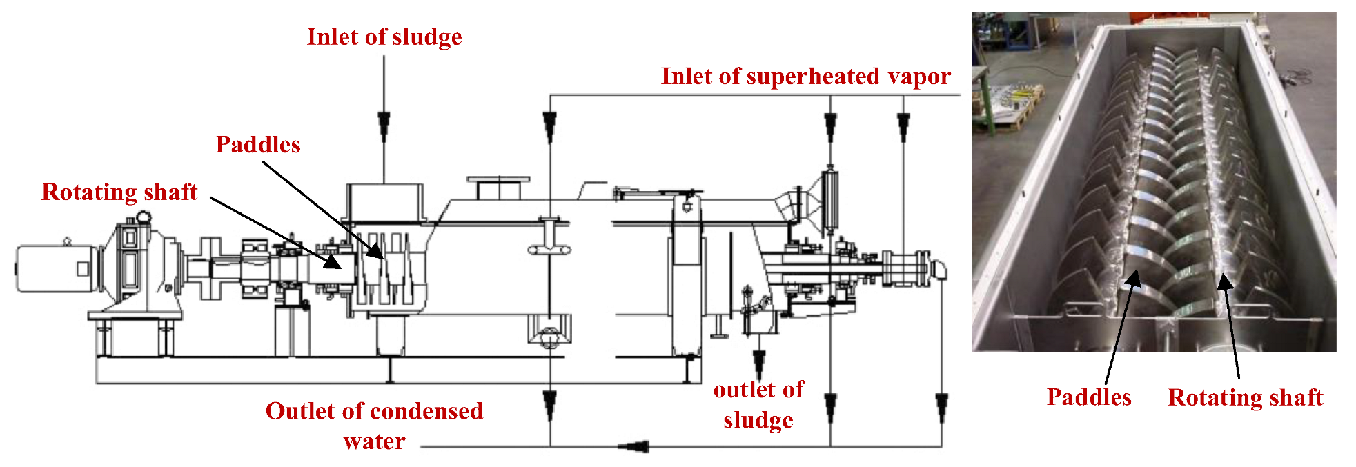
2. Geometry and Meshing

As shown in Figure 2, the actual paddles of a paddle dryer are mainly composed of two vertical fan-shaped plates, which rotate around a spindle. The surface of the fan-shaped plate is complanate. In order to capture the detailed characteristics of the droplets or liquid film produced in the steam condensation process, the meshing size should match the characteristic size of the droplets or liquid film, which results in a size for the whole paddle that is too large for CFD simulation. In order to save computational resources, a local region of a paddle with a 10 mm × 10 mm square area was selected to characterize the steam condensation performance inside the paddle in the present study. The thickness of the simulated area was 10 mm. Structural mesh was used and a total number of 1 million cells were generated, as shown in Figure 3. Due to the complexity of the condensation phenomena, the mesh was adaptively refined during the calculation to ensure correctness, using the Adaptive Mesh Refinement (AMR) function in Fluent.

3. Numerical Method

3.1. Mathematical Formulation

In this paper, a volume of fluid (VOF) model was used to simulate the condensation process of steam on the surface of the paddle. Meanwhile, the Lee condensation model was selected as the phase change model in the present study. The Lee model coupled with the VOF model has been widely used in simulating condensation heat transfer in previous studies [17,18,19]. The control equation follows.
Continuity equation:
ρ t + · ρ ν = S m
where ρ designates the density of fluid, ν designates the velocity of the fluid, and S m designates the source item in continuity equation.
Momentum equation:
t ρ ν + · ρ ν ν = p + · τ = + ρ g + F
herein, p designates the pressure, τ = designates the shear stress tensor of the fluid, g designates the vector of gravity force, and F designates the user-defined source item in momentum equation.
Energy equation:
t ρ E + · ν ρ E + p = · k e f f T j h j J j + τ = e f f · ν + S h
where E designates the energy of the fluid, T designates the temperature, and J j is the diffusion flux of species j. The first three terms on the right-hand side of the Equation represent energy transfer due to conduction, species diffusion, and viscous dissipation, respectively. S h designates the user-defined source item in energy equation.
The volume fraction of the liquid and vapor phases is calculated using a VOF model, and the governing equation is as follows:
1 ρ q t α q ρ q + · α q ρ q ν q = S q + p = 1 n m ˙ p q m ˙ q p
where m ˙ p q is the mass transfer from phase p to phase q and m ˙ q p is the mass transfer from phase q to phase p.
In this paper, the Lee model was used to consider the heat and mass transfer at the vapor–liquid interface in the condensation heat transfer process. Many scholars choose the Lee model to simulate the heat and mass transfer of evaporation condensation [24]. In the Lee model, the temperature at the vapor–liquid interface is assumed to be the saturation temperature. If the liquid phase temperature is higher than the saturation temperature or the gas phase temperature is lower than the saturation temperature, mass and heat transfer will occur at the interface. The mass source term and energy source term in the phase change process are expressed as follows:
When Tl > Tsat (evaporation):
m ˙ l v = c o e f f × α l ρ l T l T s a t T s a t
When Tv < Tsat (condensation):
m ˙ v l = c o e f f × α v ρ v T s a t T v T s a t
where subscript l designates liquid and v designates vapor. coeff is an adjustable parameter that can be interpreted as relaxation time. α and ρ are the void fraction and density of the corresponding phase, respectively. The source term of the energy equation can be expressed as the mass change rate times the latent heat of vaporization. It is important to tune the value of coeff. It has been proven that too large a value of coeff could result in a convergence problem and too small of a value may result in a large deviation between interfacial temperature and saturation temperature [7]. In the present study, the coefficient coeff was set as 80,000 s−1 based on the principle of an interfacial temperature close to the saturation temperature. In Ji et al.’s study [7], the above CFD model was proven to provide a good prediction of condensing heat transfer, with a relative deviation of 10%.

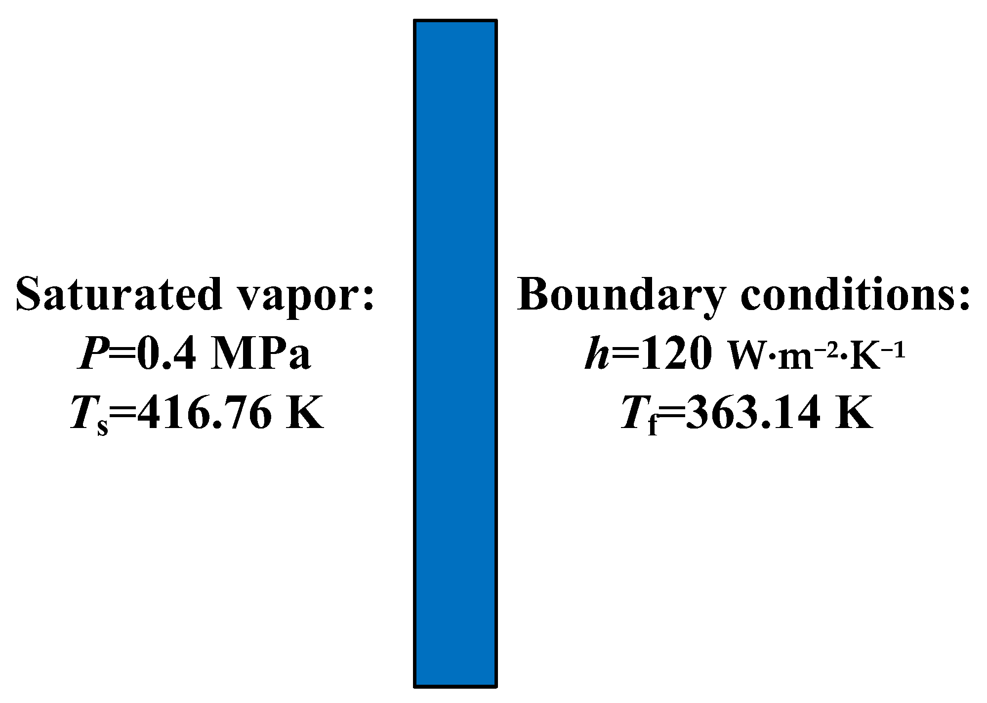
3.2. Boundary Conditions and Solver Settings

In order to accurately evaluate the effect of condensation heat transfer on a paddle dryer, the overall heat transfer process on both sides of the paddle should be considered comprehensively, instead of only the heat transfer on one side. In the present study, the condensation on the surface of the vertical plate was simulated with the third-kind boundary condition set at the other side of the plate, where the sludge temperature and heat transfer coefficient of the sludge side was given. The heat transfer coefficient of the sludge side was determined to be 120 W·m−2·K−1, according to typical experimental results in the literature [21]. The sludge temperature (working medium temperature) was selected as 363.14 K. For the vapor-condensing side, the inlet boundary condition was set as the inlet pressure boundary, where the inlet pressure and steam temperature are given. All the parameters were set as the actual operation parameters of a paddle dryer produced by Green Water Co. Ltd. in Lishui city, China. The reference pressure of the calculation domain was set as 400,000 Pa, the corresponding saturation temperature was 416.76 K, and the inlet temperature of steam was 423.15 K. The inlet steam volume fraction was set as 1. Since the steam velocity was very low in the interior of the paddle, it could be assumed that the steam velocity was 0 in the present simulation. Additionally, the other boundary conditions were set to wall boundary conditions. The boundary condition settings are given in Figure 4.
In the present study, the commercial CFD software Fluent was used to calculate the condensing heat transfer on the inner surface of a paddle. A VOF model is selected as a multiphase flow model in Fluent, and the VOF scheme is explicit. Geo-reconstruction with the highest accuracy was selected for interface reconstruction. CSF was selected for the surface tension model, and wall adhesion was used to simulate the influence of contact angle change on condensation heat transfer. In addition, the Lee model was selected for the phase change model, in which the evaporation condensation coefficient was set as 80,000 and the pressure velocity coupling mode was coupled. In order to simulate the effect of rotation on condensation heat transfer, the mesh motion function [25] was used to simulate the condensation of steam at the wall surface in the moving state. The rotation center was set at the geometric center and change different angular velocities was selected to simulate the results of condensation heat transfer. The main solver settings are shown in Table 1.
Due to the transient nature of the condensation phenomenon, we use the transient solver, select the adaptive time step option in the fluent, and set the max courant to 0.25. The initial time step is 1e−6 s, the maximum time step is 1e−4 s, and the maximum number of iterations in each time step is 20. The convergence criterion for the energy equation is set to 1e−8, and for all other equations, it is set to be 1e−4. The iteration continues in each time step until the convergence criterion is satisfied [26].

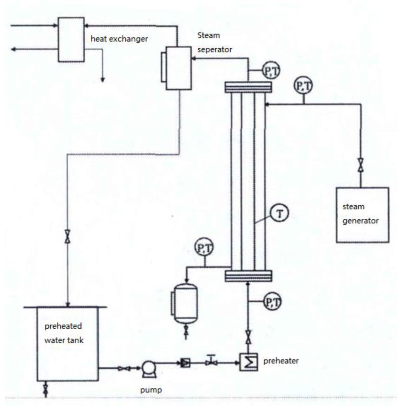
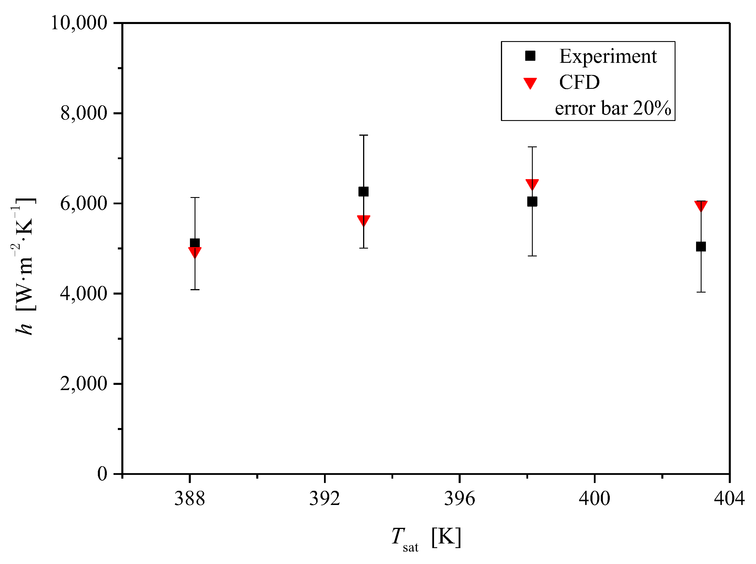
3.3. Model Verification

In the present study, the VOF model combined with the Lee model was used to simulate the condensation heat transfer on the surface of a vertical plate, which had been validated to agree well with the experimental data inside the tube in Ji et al.’s study [18]. In order to further verify the applicability of the above method for simulating condensation heat transfer on the outer surface, experimental data from Li’s study [20] were selected to validate it. The schematic diagram of the experimental set-up is given in Figure 5. The test section of this experiment was a vertical double-pipe heat exchanger. The saturated steam flowed into the tube from the upper end of the heat exchanger and condensed on the surface of the inner tube. The inner tube was made of brass, with the diameter, wall thickness, and effective heat transfer length of 32 mm, 3 mm, and 1800 mm, respectively. The inner diameter of the outer tube was 70 mm, which was much larger than that of the inner tube. A total of 4 test cases were calculated by CFD for verification. The test conditions of these cases are given in Table 2.
A comparison between the experimental data and the calculation results is shown in Figure 6. It can be seen that the condensation heat transfer coefficients outside the vertical tube calculated by the present CFD model were in good agreement with the experimental data, with the deviation within 20%. It indicates that the CFD method used in the present study for the simulation of condensation heat transfer was reliable.
The effect of wettability (contact angle) and rotational angular velocity on condensation heat transfer on the surface of the vertical paddle plate was studied by the CFD method and verified above. Four different contact angles (45°, 90°, 135°, and 180°) and two different rotational angular velocities (0 rad·s−1, 1.57 rad·s−1, and 3.14 rad·s−1) were taken into account in the present study. The rotational angular velocity of 1.57 rad·s−1 was equal to the actual rotational speed of the rotating shaft of a paddle dryer.

4. Results and Discussion

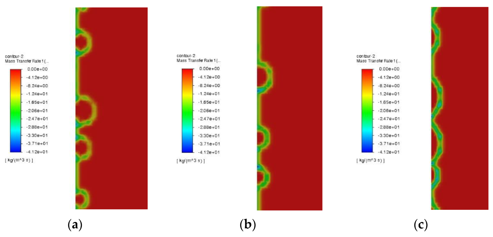
4.1. Filmwise Condensation

In the present study, the effect of surface wettability on condensation heat transfer was first analyzed. By setting different contact angles for the condensation surface, filmwise condensation and dropwise condensation could be realized. When the contact angle was set as 180 degrees, the condensation mode was film condensation, and the wall surface was covered by a layer of liquid film. Figure 7 presents the front view of the condensation surface to show the liquid film distribution when filmwise condensation occurred. The rotational angular velocity was set as 0 since only the effect of the contact angle was studied in this section. It was found that the liquid film was thinnest at the top of the vertical wall, gradually increasing along the vertical downward direction, and was thickest at the bottom. The reason for this phenomenon was the impact of gravity. Since the local heat transfer coefficient was inversely proportional to the liquid film thickness in filmwise condensation, the heat transfer coefficient and heat flux also increased with an increase in the axial height. The present simulation results for filmwise condensation were in keeping with the previous CFD study [11]. It indicated that the present CFD model could properly simulate the condensation process on a vertical surface.

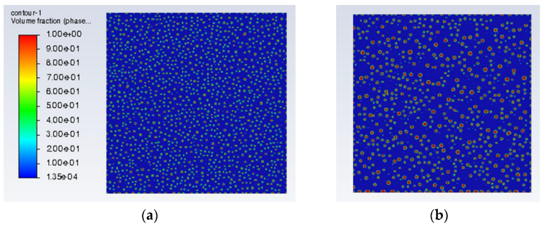
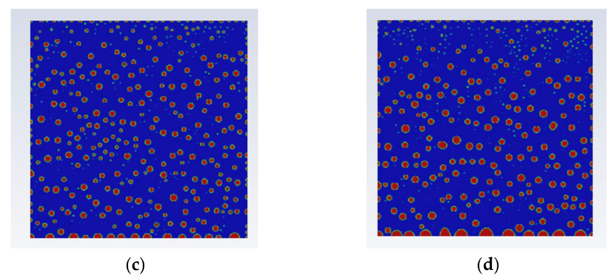
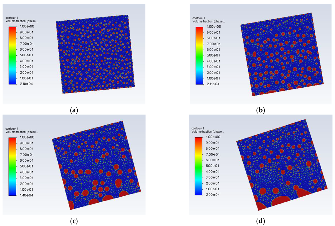
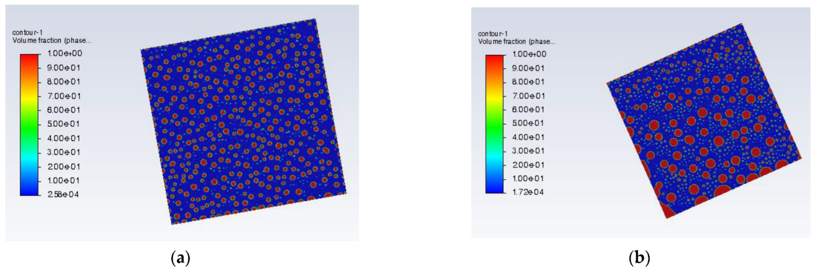
4.2. Dropwise Condensation

When the contact angle was set to less than 90 degrees, the condensed liquid on the surface formed small droplets due to surface tension, which resulted in the surface being not completely covered by the liquid film. In this case, dropwise condensation was generated. Droplet distribution and behavior during condensation is shown in Figure 8. Rotational angular velocity was set as 0. It was found that the droplets randomly formed on the vertical surface. The droplet behavior along the vertical surface included droplet growth, slippage, and coalescence. The droplet size was small at the very beginning and grew gradually with the increase in calculation time. Once the size of the droplet increased to a certain value, the droplet slid vertically down, owing to the effect of gravity. Droplet coalescence also occurred when droplets met each other during the slipping process. Owing to droplet movement, the distribution of the liquid fraction gradually increased from the top to the bottom of the vertical surface. The simulation results showed that the present CFD method was able to model the dropwise condensation process on a vertical surface.
Figure 9 presents the shapes of droplets at different contact angles. It was found that the present CFD model was able to simulate the effect of contact angles on a single droplet, which was the foundation of a reasonable prediction of condensation heat transfer. It should be noted that dropwise condensation could be observed at the contact angle of 135° at the very beginning. Filmwise condensation would ultimately occur since the droplets with a relatively larger contact angle easily connected to form film in this case.
The mass transfer rate near the vertical surface is given in Figure 10. It was found that the greatest mass transfer occurred on the bare surface between the droplets, since vapor could directly contact the cold wall. Another small amount of mass transfer occurred on the surfaces of droplets, owing to interfacial heat transfer. This indicates that the reason for heat transfer enhancement in dropwise condensation was that larger areas of bare surface were generated compared to film condensation. In addition, with a decrease in contact angle, the contact area of the droplets also decreased, which resulted in larger areas of bare surface and enhanced condensation heat transfer.

4.3. Heat Transfer Performance of Filmwise and Dropwise Condensation

Once the liquid film changed into droplets with the increase in contact angle, the heat transfer condensing coefficient increased with the change of liquid phase behavior. Table 3 presents a comparison of heat transfer coefficients between filmwise condensation and dropwise condensation. It was observed that the heat transfer coefficient of dropwise condensation was more than double that of filmwise condensation. According to Chen et al.’s study, realizing dropwise vapor condensation inside a dryer paddle was expected to improve the steam condensation rate as well as the overall drying efficiency and performance of the dryer.
To further analyze the effect of wettability on sludge drying on the other side, the equivalent evaporation rate of water in sludge was calculated by converting the sludge temperature and latent heat of vaporization, as shown in Table 4. It can be seen that the wall temperature and evaporation rate increased when dropwise condensation occurred. The calculated equivalent evaporation rates of filmwise condensation and dropwise condensation were 7.42 kg·h−1 and 7.80 kg·h−1, respectively, under the actual operation conditions of the paddle dryer, which was in accord with that of the actual paddle dryer. That was to say, an approximately 5% increase in drying performance of the paddle dryer was likely to be provided by changing the wettability of the inner surface of the paddle.

4.4. The Effect of Rotation on Condensation Heat Transfer Performance

In an actual running paddle dryer, the paddles rotate around the main spindle with a certain rotational speed. To discuss the applicability of a surface modification method inside the paddle, the effect of rotation should be considered in the CFD simulation. Based on the analysis of the cases without rotation, it was indicated that the movement behavior of droplets can determine condensation heat transfer performance.
The droplet movement and distribution at a rotational angular velocity of 1.57 rad·s−1 and contact angle of 90° is given in Figure 11. This rotational angular velocity was in accord with that of the actual paddle dryer. The rotation direction was counterclockwise and the rotation center was set at the geometric center. It was observed that the vapor randomly condensed on the whole wall surface. Owing to the effect of surface tension, the droplets with small size gradually increased and moved downward under the effect of gravity, accompanied by the process of coalescence among different liquid droplets. Compared to the case without rotation, it was found that droplet coalescence grew greater and the droplet size was much larger at the same time. The possible reason for this phenomenon was that the effect of rotation led to the local relative slip of droplets and enhanced the chance of droplets contacting and coalescing. In addition, the droplets tended to accumulate at the lowest location of the vertical wall owing to the effect of gravity.
Figure 12 shows the variation in droplet distribution in dropwise condensation against calculation time at a rotational angular velocity of 3.14 rad·s−1 and contact angle of 90°. The rotation direction was counterclockwise, and the rotation center was set at the geometric center. Similar droplet movement behavior can be observed in this figure, in that the droplets tended to move along the direction of gravity. There was no essential difference in droplet distribution found in the present study when the rotational angular velocity increased from 1.57 rad·s−1 to 3.14 rad·s−1.
To further discuss condensation heat transfer performance under rotation conditions, the wall temperature and equivalent evaporation rate on the other side of the rotation wall under both filmwise and dropwise condensation conditions were analyzed. Table 5 presents the effect of rotation velocity on wall temperature and the equivalent evaporation rate in filmwise condensation. In general, both wall temperature and the equivalent evaporation rate were almost unchanged with the change in rotational angular velocity under a filmwise condensation condition. The combined effects of centrifugal force and gravity on film distribution was complicated, and needs to be further analyzed. Table 6 presents the effect of rotation velocity on wall temperature and the equivalent evaporation rate in dropwise condensation. It was found that rotational motion might cause a decrease in wall temperature and the equivalent evaporation rate under the condition of dropwise condensation. A possible reason for this phenomenon was that rotation could result in longer residence times for droplets on the surface, because of the action of centrifugal force and the change in relative location of the vertical plate. In addition, variation in rotational angular velocities did not significantly affect heat transfer performance in dropwise condensation. Compared to the case of filmwise condensation with rotation, the equivalent evaporation rate only increased by 2.4% at the same rotational angular velocity. It seems that changing the surface wettability inside the paddle would not be an effective means to enhance the heat transfer and drying efficiency of a paddle dryer under rotation conditions. Techniques to enhance the heat transfer between sludge and surface or increase the heat transfer area would be better measures to improve the drying efficiency of a rotational paddle dryer.

5. Conclusions

In this paper, the applicability of advanced heat transfer enhancement technology to a paddle dryer was discussed. A CFD method was used to simulate the condensation heat transfer on the inner surface of a dryer paddle. The influence of surface wettability and rotation on condensation heat transfer and droplet behavior were studied. The main conclusions in the present study were as follows:
The present CFD model could properly simulate the condensation process on a vertical surface. With a decrease in contact angle, the condensed liquid film on the surface became small liquid droplets and the filmwise condensation turned into dropwise condensation, which resulted in a significant increase in the heat transfer coefficient.
Owing to droplet movement caused by gravity, both the liquid film thickness in filmwise condensation and the liquid fraction in dropwise condensation gradually increased from the top to the bottom of the vertical surface.
The wall temperature and evaporation rate increased when dropwise condensation occurred. An approximately 5% increase in drying performance was expected to be provided by changing the wettability of the inner surface of the paddles.
When rotating, the wall temperature and the equivalent evaporation rate were almost unchanged with a change in rotational angular velocity under a filmwise condensation condition. However, the rotational motion might cause a decrease in wall temperature and the equivalent evaporation rate under a dropwise condensation condition. Rotation could result in a longer residence time for droplets, a higher probability of droplet coalescence, and larger droplet size on the surface.
Compared to the case of filmwise condensation with rotation, the equivalent evaporation rate only increased by 2.4%, which meant that changing surface wettability inside the paddle would not be an effective means to enhance the heat transfer and drying efficiency of a rotating paddle dryer. Techniques to enhance the heat transfer between sludge and surface or increase the heat transfer area would be better measures to improve the drying efficiency of a rotational paddle dryer.

Author Contributions

Conceptualization, W.L.; Methodology, W.L. and M.G.; Software, M.G. and Y.Z.; Validation, M.G.; Formal analysis, Y.Z.; Investigation, Y.Z. and Z.L.; Writing—original draft, W.L.; Writing—review & editing, M.G. and Z.L. All authors have read and agreed to the published version of the manuscript.

Funding

This research received no external funding.

Institutional Review Board Statement

Not applicable.

Informed Consent Statement

Not applicable.

Data Availability Statement

No new data were created.

Conflicts of Interest

The authors declare no conflict of interest.

References

  1. Arlabosse, P.; Chavez, S.; Lecomte, D. Method for Thermal Design of Paddle Dryers: Application to Municipal Sewage Sludge. Dry. Technol. 2004, 22, 2375–2393. [Google Scholar] [CrossRef]
  2. Imoto, Y.; Kasakura, T.; Hasatani, M. The State of the Art of Sludge Drying in Japan. Dry. Technol. 1993, 11, 1495–1522. [Google Scholar] [CrossRef]
  3. Yamahata, Y.; Izawa, H.; Hasama, K. Experimental Study on Application of Paddle Dryers for Sludge Cake Drying. In Drying ’85; Springer: Kyoto, Japan, 1984. [Google Scholar]
  4. Milhé, M.; Sauceau, M.; Arlabosse, P. Modeling of a Continuous Sewage Sludge Paddle Dryer by Coupling Markov Chains with Penetration Theory. Appl. Math. Model. 2016, 40, 8201–8216. [Google Scholar] [CrossRef] [Green Version]
  5. Charlou, C.; Sauceau, M.; Arlabosse, P. Characterisation of Residence Time Distribution in a Continuous Paddle Dryer. J. Residuals Sci. Technol. 2013, 10, 117–125. [Google Scholar]
  6. Jamaleddine, T.J.; Ray, M.B. Drying of Sludge in a Pneumatic Dryer Using Computational Fluid Dynamics. Dry. Technol. 2011, 29, 308–322. [Google Scholar] [CrossRef]
  7. Mezhericher, M.; Levy, A.; Borde, I. Three-dimensional modelling of pneumatic drying process. Powder Technol. 2010, 203, 371–383. [Google Scholar] [CrossRef]
  8. El-Behery, S.M.; El-Askary, W.A.; Hamed, M.H.; Ibrahim, K.A. Numerical simulation of heat and mass transfer in pneumatic conveying dryer. Comput. Fluids 2012, 68, 159–167. [Google Scholar] [CrossRef]
  9. Chen, S.; Wang, F.; Milhé, M.; Arlabosse, P.; Liang, F.; Chi, Y.; Nzihou, A.; Yan, J. Experimental and Theoretical Research on Agitated Contact Drying of Sewage Sludge in a Continuous Paddle Dryer. Dry. Technol. 2016, 34, 1979–1990. [Google Scholar] [CrossRef]
  10. Taler, D.; Ocłoń, P. Thermal contact resistance in plate fin-and-tube heat exchangers, determined by experimental data and CFD simulations. Int. J. Therm. Sci. 2014, 84, 309–322. [Google Scholar] [CrossRef]
  11. Peng, B.; Ma, X.; Lan, Z.; Xu, W.; Wen, R. Analysis of condensation heat transfer enhancement with dropwise-filmwise hybrid surface: Droplet sizes effect. Int. J. Heat Mass Transf. 2014, 77, 785–794. [Google Scholar] [CrossRef]
  12. Xie, J.; She, Q.; Xu, J.; Liang, C.; Li, W. Mixed dropwise-filmwise condensation heat transfer on biphilic surface. Int. J. Heat Mass Transf. 2020, 150, 119273. [Google Scholar] [CrossRef]
  13. Han, X.; Yao, B.; Guan, J.; Zhu, Q.; Han, Z. Effect of the surface tension correction coefficient on the nonequilibrium condensation flow of wet steam. Appl. Therm. Eng. 2022, 210, 118335. [Google Scholar] [CrossRef]
  14. Orejon, D.; Shardt, O.; Gunda, N.S.K.; Ikuta, T.; Takahashi, K.; Takata, Y.; Mitra, S.K. Simultaneous dropwise and filmwise condensation on hydrophilic microstructured surfaces. Int. J. Heat. Mass. Transf. 2017, 114, 187–197. [Google Scholar] [CrossRef]
  15. Cheng, Y.; Xu, J.; Sui, Y. Numerical Investigation of Coalescence-Induced Droplet Jumping on Superhydrophobic Surfaces for Efficient Dropwise Condensation Heat Transfer. Int. J. Heat Mass Transf. 2016, 95, 506–516. [Google Scholar] [CrossRef]
  16. Wang, X.; Chang, H.; Corradini, M. A CFD Study of Wave Influence on Film Steam Condensation in the Presence of Non-Condensable Gas. Nucl. Eng. Des. 2016, 305, 303–313. [Google Scholar] [CrossRef]
  17. Ke, Z.; Shi, J.; Zhang, B.; Chen, C.L. Numerical Investigation of Condensation on Microstructured Surface with Wettability Patterns. Int. J. Heat Mass Transf. 2017, 115, 1161–1172. [Google Scholar] [CrossRef]
  18. Ji, W.T.; Mao, S.F.; Chong, G.H.; Zhao, C.Y.; Zhang, H.; Tao, W.Q. Numerical and Experimental Investigation on the Condensing Heat Transfer of R134a Outside Plain and Integral-Fin Tubes. Appl. Therm. Eng. 2019, 159, 113878. [Google Scholar] [CrossRef]
  19. Liu, Z.; Wu, H. Numerical Study on Filmwise Condensation Heat Transfer Based on VOF Model. J. Therm. Sci. Technol. 2014, 13, 126–130. [Google Scholar]
  20. Li, J. Experimental Study on Phase Change Heat Transfer Enhancement in Vertical Tube; East China University of Science and Technology: Shanghai, China, 2014. [Google Scholar]
  21. Cao, T. Study on the Drying and Reutilization of Industrial Sludge; North China Electric Power University: Beijing, China, 2016. [Google Scholar]
  22. Mohammed, H.I.; Giddings, D.; Walker, G.S. CFD Multiphase Modelling of the Acetone Condensation and Evaporation Process in a Horizontal Circular Tube. Int. J. Heat Mass Transf. 2019, 134, 1159–1170. [Google Scholar] [CrossRef]
  23. Xia, B.; Sun, D.-W. Applications of computational fluid dynamics (CFD) in the food industry: A review. Comput. Electron. Agric. 2002, 34, 5–24. [Google Scholar] [CrossRef]
  24. Kharangate, C.R.; Mudawar, I. Review of computational studies on boiling and condensation. Int. J. Heat Mass Transf. 2017, 108, 1164–1196. [Google Scholar] [CrossRef]
  25. Raza, N.; Ahsan, M.; Mehran, M.T.; Naqvi, S.R.; Ahmad, I. Comparative hydrodynamics study of fluidized bed gasifier incorporating static and rotating air distributor plates: A CFD approach. Powder Technol. 2022, 405, 117500. [Google Scholar] [CrossRef]
  26. Khan, Z.A.; Ahmad, N.; Sattar, M.; Haq, M.A.; Khan, I.; Hamid Ganie, A. Cell alternation algorithm for simulating bubble growth in boiling flows through volume of fluid (VOF) method in fluent. Alex. Eng. J. 2022, 61, 13051–13066. [Google Scholar] [CrossRef]
Figure 1. Schematic of the paddle dryer.
Energies 16 00901 g001
Figure 2. Schematic of the paddles and the rotating shaft of the dryer.
Energies 16 00901 g002
Figure 3. Schematic diagram of meshing.
Energies 16 00901 g003
Figure 4. Schematic diagram of the third-boundary conditions.
Energies 16 00901 g004
Figure 5. Schematic diagram of experimental setup in Li’s study.
Energies 16 00901 g005
Figure 6. Comparison between the calculated result and experimental data.
Energies 16 00901 g006
Figure 7. Liquid film distribution of filmwise condensation.
Energies 16 00901 g007
Figure 8. Droplet distribution of dropwise condensation with θ = 90°: (a) t = 0.2 s; (b) t = 0.4 s; (c) t = 0.6 s; (d) t = 0.8 s.
Energies 16 00901 g008aEnergies 16 00901 g008b
Figure 9. Droplet shapes at different contact angles: (a) θ = 45°; (b) θ = 90°; (c) θ = 135°.
Energies 16 00901 g009
Figure 10. Mass transfer rate at different contact angles: (a) θ = 45°; (b) θ = 90°; (c) θ = 135°.
Energies 16 00901 g010
Figure 11. Droplet movement and distribution against time at a rotational angular velocity of 1.57 rad·s−1 and contact angle of 90°: (a) 0.2 s; (b) 0.3 s; (c) 0.4 s; (d) 0.5 s.
Energies 16 00901 g011
Figure 12. Droplet movement and distribution against time at a rotational angular velocity of 3.14 rad·s−1 and contact angle of 90°: (a) 0.2 s; (b) 0.3 s.
Energies 16 00901 g012
Table 1. Solver settings.
ParametersSetup
VOF temporal discretizationExplicit
VOF spatial discretization schemeGeo-reconstruct
Surface tension force modelCSF
Evaporation/condensation modelLee
Saturation temperature416.76
Domain rotationMesh motion
Table 2. Experimental conditions of verified data.
No.Vapor Temperature/KInlet Pressure/kPaWall Temperature/K
1388.15167.81382.15
2393.15197.34385.84
3398.15230.89388.66
4403.15268.95389.96
Table 3. Comparison of heat transfer coefficients between filmwise condensation and dropwise condensation.
Contact Angle (°)Condensation ModeHeat Transfer Coefficients (W·m−2·K−1)
45Dropwise condensation19,177.67
90Dropwise condensation17,966.29
180Filmwise condensation8583.72
Table 4. Comparison of the equivalent evaporation rates between filmwise condensation and dropwise condensation.
Contact Angle (°)Condensation ModeWall Temperature (K)Evaporation Rate (kg·h−1)
180Filmwise condensation411.97.42
90Dropwise condensation414.17.80
Table 5. Comparison of the equivalent evaporation rates in filmwise condensation at different rotational angular velocities.
Contact Angle (°)Angular Velocity (rad·s−1)Wall Temperature (K)Evaporation Rate (kg·h−1)
1800411.97.42
1801.57411.87.41
1803.14411.87.41
Table 6. Comparison of the equivalent evaporation rates in dropwise condensation at different rotational angular velocities.
Contact Angle (°)Angular Velocity (rad·s−1)Wall Temperature (K)Evaporation Rate (kg·h−1)
1801.57411.87.41
900414.17.80
901.57412.97.59
903.14412.97.59
Disclaimer/Publisher’s Note: The statements, opinions and data contained in all publications are solely those of the individual author(s) and contributor(s) and not of MDPI and/or the editor(s). MDPI and/or the editor(s) disclaim responsibility for any injury to people or property resulting from any ideas, methods, instructions or products referred to in the content.

