Article

Cosimulation of Integrated Organic Photovoltaic Glazing Systems Based on Functional Mock-Up Unit

1
Departamento de Ingeniería Mecánica, Universidad del Bío-Bío, Concepción 4051381, Chile
2
Mechanical Engineering Graduate Program, Pontificia Universidade Católica do Paraná, Curitiba 80910-215, Brazil
*
Author to whom correspondence should be addressed.
These authors contributed equally to this work.
Energies 2023, 16(2), 951; https://doi.org/10.3390/en16020951
Submission received: 31 October 2022 / Revised: 15 December 2022 / Accepted: 28 December 2022 / Published: 14 January 2023
(This article belongs to the Special Issue Innovative Design and Research on Solar Thermal Systems)

Abstract

:
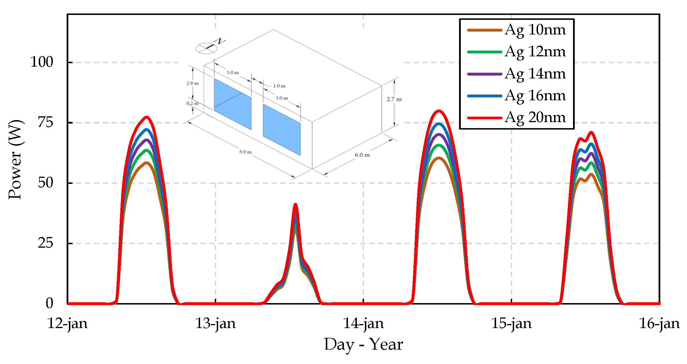
This study presents an approach to simulating building-integrated photovoltaic glazing systems composed of semitransparent organic photovoltaic (ST-OPV) elements. The approach consists of a mathematical cosimulation model based on the energy balance of complex glazing systems, considering heat transfer as conduction, mixed convection, and radiation effects. The cosimulation method is based on a functional mock-up unit (FMU) developed in Python and the building simulation program Domus. This work aims at presenting a cosimulation technique that can be easily applied to building energy simulation tools for the assessment of photovoltaic energy generation in glazing systems. The cosimulation glazing model was verified according to ANSI/ASHRAE Standard 140-2011, and the zone temperature was kept within with a root medium square error (RMSE) of 1.45 °C. The simulated building with an ST-OPV system showed promising results and could be applied to near-zero energy buildings since each 6-m 2 glazing has a power generation of around 77 W, equivalent to 9% of available solar resource.

1. Introduction

Energy plays a vital role in human society. Buildings consume around 32% of globally produced energy [1], and this figure is expected to reach 40% by 2040 [2]. Due to this increase, if we want to mitigate some consequences of climate change, we must reduce energy consumption. Because more developed countries consume more electricity, it is important to investigate optimization strategies to produce efficient energy for infrastructures such as buildings. A building can last from 50 to 100 years, sometimes even longer, which is why it is important to incorporate energy-efficient technology from its first stages. Since solar energy is inexhaustible, clean, and the most abundant form of all renewable energy sources, there is a rising interest in photovoltaics; solar radiation can be converted into electricity through semiconductors [3]. Building-integrated photovoltaics (BIPV) are an excellent way to contribute to energy harvesting. In addition, integrated PV modules contribute to human comfort in the building; they serve as weather protection, heat insulation, shading modulation, noise protection, thermal isolation, and electromagnetic shielding [4]. Many studies have investigated BIPV, some of which are cited here. These studies also sought evaluate the contribution of organic materials of semitransparent solar energy generation incorporated in the windows of the selected model as an energy-generating mechanism, and as a tool to control the interior temperature of the thermal zone. Ordenes et al. [5] studied in detail a BIPV application for Brazil. The authors analyzed the potential of seven BIPV technologies implemented to harvest solar radiation in a residential prototype, simulated in three different cities, namely, Natal, Brasília, and Florianópolis. Joseph et al. [6], and Shukla et al. [7] indicated that the radiant energy harnessed through BIPV and other technologies can contribute to improvements in heating, solar thermal energy, and even artificial photosynthesis. The authors also found that the implementation of semitransparent BIPV is an energy generation approach that integrates photovoltaic technologies into buildings to harvest solar energy in various forms, and leads to a direct reduction in CO 2 emissions. This integration with organic elements is possible due to the technological advancements of semitransparent photovoltaics. Stoichkov et al. [8], in a simulated experimental array, researched the outdoor performance of organic building-integrated photovoltaics (OBIPVs), which showed strong potential, with excessive energy generation for 8 months per year based upon a 4.22 kWp OBIPV system. In the optimization of molecular structures of organic photovoltaic (OPV) materials, Cui et al. [9] presented an effective method to boost power conversion efficiency (PCE); through single-junction OPV cells, the molecular system achieved 17.3% efficiency. Schopp and Brus [10] presented a complete review of current ST-OPV-based technologies that shows devices with higher or lower transparency and the resulting implications, clearly serving as a reference point for the systematic development of the next generation of this technology. Regarding the simulation used to predict the benefits of new solar-related technologies, different simulation and modelling tools often have their own definition of how a phenomenon can be represented, and how model data is stored. Complications arise when we develop model parts in one tool and try to export the final model to another tool or when we attempt to verify a result by using a different simulation tool. The functional mock-up interface (FMI) [11] is a standard that provides a unified model execution interface to exchange dynamic system models between modelling tools and simulation tools. A model that follows the FMI is called a functional mock-up unit (FMU). This standard has earned widespread renown among users, and the support of numerous commercial and open-source tools. The FMI gives a great deal of attention to the simulation of dynamic system models, specifically the simulation of coupled dynamic systems. Wetter [12], and Wetter and van Treeck [13] described the implementation of a software environment that allows for different simulation programs to exchange data during the time integration, conducting hardware into the loop simulation with EnergyPlus [14], MATLAB [15], Simulink [16], and the Modelica [17] modelling and simulation environment Dymola [18]. Nouidui et al. [19] described the development and the implementation of the functional mock-up unit (FMU) for the cosimulation import interface in EnergyPlus. This study focuses on simulating a code developed in Python 3.7 [20] with whole-building hygrothermal simulation software DOMUS [21], and the application of the FMI standard (direct or indirect) to evaluate complex glazing systems or complex fenestration systems as described in Laouadi [22]. Building energy simulation tools are commonly developed in such a way that their management and evolution can be very difficult and time-consuming. In this way, this work aims at presenting a cosimulation technique that can be easily applied to building energy simulation tools for the assessment of photovoltaic energy generation in glazing systems. The development of a new functional mock-up unit to cosimulate photovoltaic energy generation in glazing systems is presented, which enables the software development in collaboration with different partners without the need to modify and recompile the main program by means of an open-source program such as Python. The authors see it as a developing area where researchers can focus only on their own model and not on the whole code, which may also stimulate cooperation with manufacturers without the understanding of a complex computer code. The FMI standard is a viable solution for the development and research of new models as the one proposed in the present paper. The simulation of glazing systems was based on the spectral radiative properties of nonopaque materials. Furthermore, mathematical codes were developed for simulation and energy evaluation for this study. This work presents a cosimulation technique that can be easily applied to building energy simulation tools for the assessment of photovoltaic energy generation in glazing systems.

2. Materials and Methods

The modelling of glazing systems is not a simple task because it requires consistent physical and mathematical models. As is described below, the ST-OPV material can be added or deposited on a substrate. The following sections describe the simulation software tools and the integration of this solar harvester material on glazing as a thin-film approach.

2.1. Simulation Software Tools

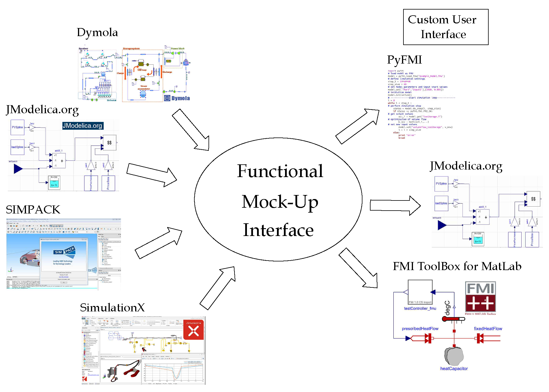
A vast number of methods have been developed to mathematically solve ordinary differential equations and differential–algebraic equations in order for researchers to physically model certain phenomena, such as heat and mass transfer. Numerical methods can be easily implemented in different programming languages and with different interfaces. In this study, we selected the high-level programming languages Octave [23] for the development of the mathematical code and Python 3.7 [20] for computing implementation because they are both compatible with GNU General Public License. Accessing these tools through a unified interface is necessary not only for the academic community and for education purposes, but also for industrial use. An industrial model of a dynamic system is usually not only a set of differential equations. These models may contain discrete controllers, impacts, or friction, which results in discontinuities that must be handled by a modern solver correctly and efficiently. In addition, models may produce an enormous amount of data, which puts strain on the simulation software. Figure 1 [24] presents a mathematical cosimulation scheme where each solver can work at different stages and exchange bidirectional information.

2.2. Functional Mock-Up Interface

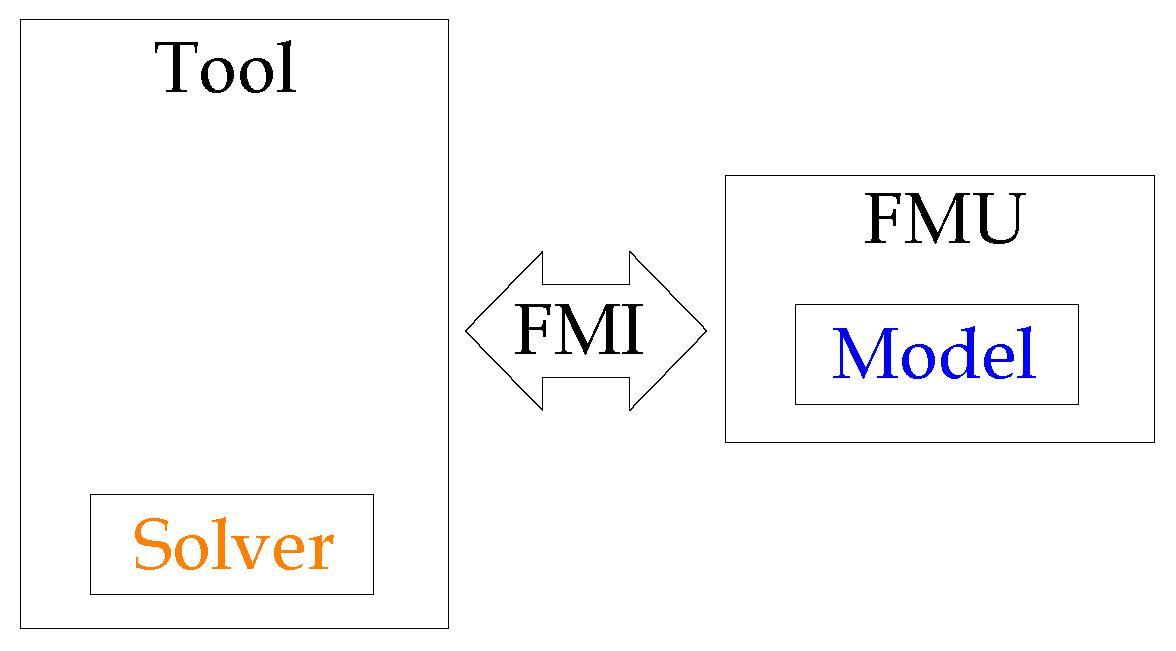
The functional mock-up interface (FMI) [11] is a standard designed to provide a unified execution interface for dynamic system models to integrate modelling and simulation tools. The idea is that tools generate and exchange models that adhere to the FMI specification called functional mock-up units (FMUs). This approach enables users to create models in one modelling environment, connect them to a second one, and simulate the complete system using a third simulation tool, as presented in Figure 2 on the basis of Fritzson et al. [11].
The generated FMU models are distributed and shared as compressed archives. They include either the source files for the model, allowing for a user to have full access to the internals, or a shared object file containing the model’s information accessed through the FMI interface. Furthermore, both the source files and the shared object file can be included in the FMU. The archive additionally provides an XML file containing metadata of the model, such as the sizes of the dynamic system and the names of variables, parameters, constants, and inputs, additional information that does not impact a simulation of the model, but may be relevant to distribute with the FMU, such as documentation. The FMI was developed by a European project, MODELISAR [25], focused on improving the design of systems and embedded software in vehicles. The standard is now maintained and developed by the Modelica Association [17]. Since its release, the standard has received a significant amount of attention among both tool vendors and users. There are currently over 70 tools [24]; some examples include the commercial products Dymola [18] and SIMPACK [26], and open-source platform JModelica.org [27]. The large number of tool vendors that have adopted the standard show that there is a real and pressing need to be able to export and import dynamic system models between existing tools and to develop custom simulation environments.

2.3. Cosimulation

For cosimulation, the standard describes a discrete interface to the underlying dynamic model, i.e., giving the current internal state, input u n , and step size H of the model returns the outputs y n + 1 , at a time T n + H = T n + 1 ,
y n + 1 = f ( H , u n ; p ) ,
where p are the parameters. The advancement of the states and time is completely hidden outside of the model and is not specified by the standard. Consequently, if there are events, these are also handled internally and are not visible from the outside. However, since the advancement is hidden, this allows for specialized solvers to be used for the particular subsystem at hand, which may improve performance and simulation stabilization. A scheme of this can be seen in Figure 3; the solver is the Python script for this case of study.

2.4. Integration of Glazing and Films

In this section, we unveil the approach to evaluate the radiative properties of the semitransparent organic photovoltaic material available in the literature. The idea is to model this material as a reflective film attached to the interior surface of a double-panel glazing system. Regarding the radiative properties of glazing systems, such as transmittance, reflectance, and absorbance at different incidence angles, Riquelme et al. [28] developed a mathematical integration for directional averages, and this was introduced to calculate the radiative properties according to the incidence of solar angles as a continuous function.

2.5. Modelling of Thin Films

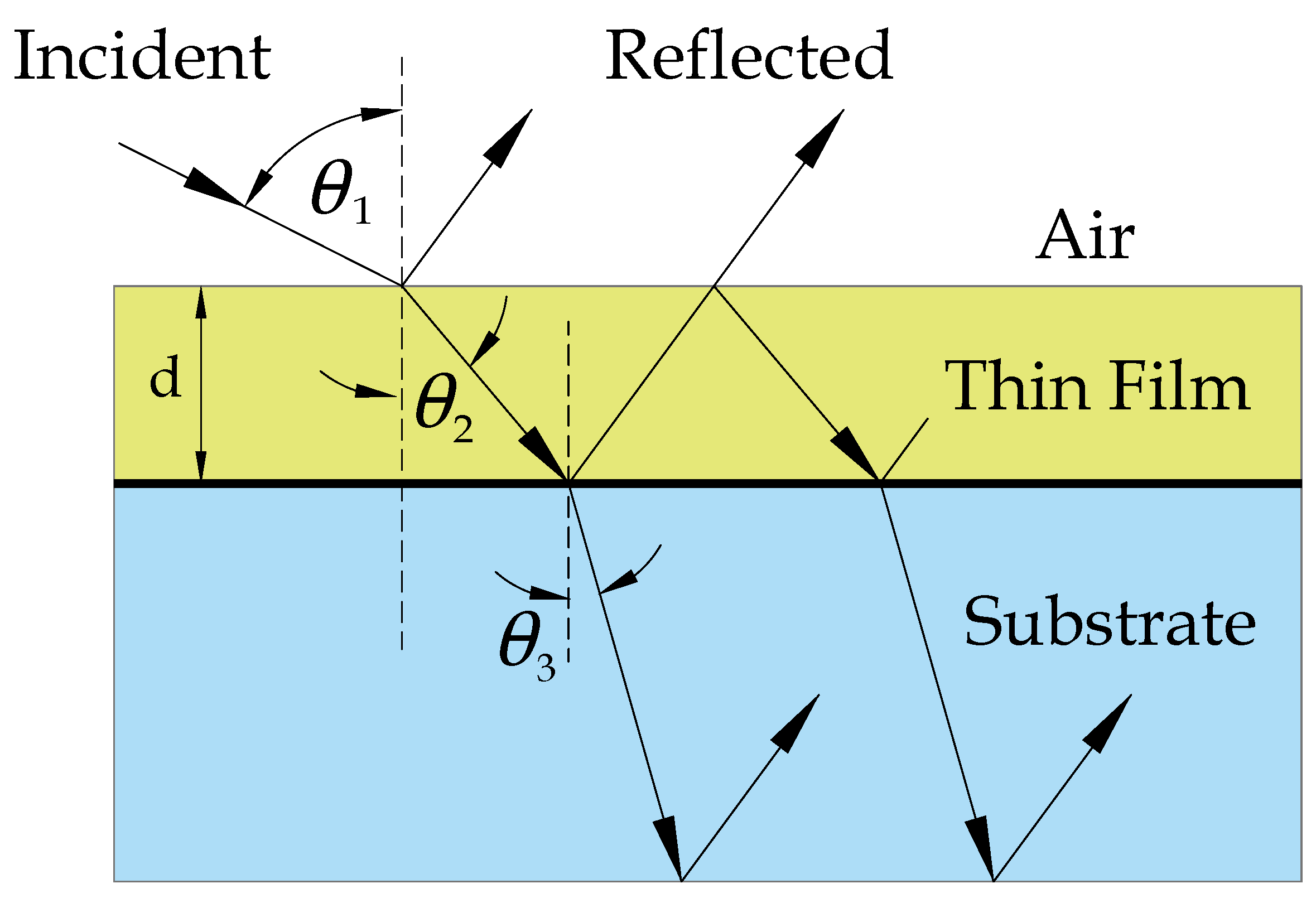
Although many unsolved problems remain on this area, the general features of the optical behavior of thin films are fairly developed. Heavens [29] indicated that progress in the methods of studying structures of films continues to grow, aiding in the solution of interpretation questions regarding optical phenomena. Meanwhile, further developments in the field of high-speed computing contribute to a reduction in the labor involved in studying the properties of multiple-film systems. On that subject, we cite the mathematical treatment for thin films based on Schuster [30], a recent study, and the classical approaches of Walton [31], Heavens [29], and Born and Wolf [32]. A reflective film is treated as a smooth, thin coating on one side of the glass pane. Figure 4 shows a schematic representation of the investigated optical system: a thin film on top of a thick substrate. The boundary on the second side of the substrate is not shown. In general, the medium behind the substrate is identical to Medium 1 (air).
The mathematical treatment of the optics of a metallic composed film presented by Heavens [29], and Born and Wolf [32] is based on the index of refraction of the metal, which is a complex number as shown in Equation (2).
n ^ 2 = n 2 i k 2 ( i = 1 )
where n 2 is the (real) index of refraction, and k 2 is the extinction coefficient. Snell’s law can be still applied, but it leads to a complex value of cos θ ^ 2 = x + i y . Thus to obtain these values,
a = n 1 s i n θ 1 n 2 n 2 2 + k 2 2 2 b = n 1 s i n θ 1 k 2 n 2 2 + k 2 2 2
then
x = 1 a + b + ( 1 a + b ) 2 + 4 a b 2
and
y = a k 2 x n 2
The amplitude (not energy) reflectance at the interface between media i and j for the incident radiation from medium i is given by
ρ ^ i j = p ^ i p ^ j p ^ i + p ^ j
where,
p ^ i = c o s θ ^ i n ^ i [ T E p o l a r i z a t i o n ]
p ^ i = n ^ i c o s θ ^ i [ T M p o l a r i z a t i o n ] .
The amplitude transmittance at an interface is given by
τ ^ i j = 2 p ^ i p ^ i + p ^ j
p ^ j i = p ^ i j and τ ^ i j = 1 ρ ^ j i 2 .
Amplitude transmittance ( τ ^ f ) within the metallic film is based on its phase thickness and is defined as follows:
d ^ = 2 π d n ^ 2 c o s θ ^ 2 λ
where d is the thickness of the film, and λ is wavelength spectra. So,
τ ^ f = e i d ^
When multiple reflections within the film are considered, we are led to expressions for the total amplitude reflectance and transmittance. For radiation incident from Medium 1, the expressions are
ρ ^ 13 = ρ ^ 12 + ρ ^ 23 τ ^ f 1 + ρ ^ 12 ρ ^ 23 τ ^ f 2 τ ^ 13 = τ ^ 12 + τ ^ 23 τ ^ f 1 + ρ ^ 12 ρ ^ 23 τ ^ f 2 .
By reversing the subscripts for radiation incident from Medium 3, the energy reflectance and transmittance are given by
ρ 13 = ρ ^ 13 ρ ¯ 13 τ 13 = τ ^ 13 τ ¯ 13 ρ ^ 3 ρ ^ 1
where ρ ¯ and τ ¯ are the complex conjugates of ρ ^ and τ ^ . Energy is absorbed in the film ( ρ 13 + τ 13 < 1 ).
Most of the expressions above are complex. Rather than expanding them to obtain solutions in terms of real numbers, it is easier to let the computer evaluate the expressions by complex arithmetic. Optical constants, such as refraction coefficient and extinction coefficient, are not available directly at the source, but an estimate of these values can be obtained from the available spectral transmittance. Gao et al. [33] stated that a typical reflectance for a TiO 2 surface due to the near-infrared reflectance of this composite pigment reaches 0.68. Average spectral values on this case were calculated using the Kramer–Konig relations for connecting the real and imaginary parts of any complex function, as was presented by Rubin [34], and developed from reflectance measurements for clear glass on Riquelme et al. [35].

2.6. Integration of Photovoltaic Glazing in Buildings Based on Thin Films

Clarke [36] described an approach for an integrated photovoltaic façade based on Buresch [37] taking into account the façade temperature. Current studies, such as the work described by Stoichkov et al. [8], employed this approach to ST-OPVs integration in glazing systems for solar-energy harvesting. Solar radiation is transmitted to the surface of the photovoltaic layer through the cover via the processes described in the previous section. Before this flux is applied to the corresponding finite-volume (FV) conservation equation, the flux magnitude is reduced to reflect the fact that not all absorbed solar radiation α i is converted into heat since a proportion is converted into electrical energy:
α i = α i + q e i ,
where α i is the actual absorption and q e i is the photovoltaic power output (W), which may be determined from the following model:
q e i = n c V i I g 1 e V i θ i λ σ i V i I s c α i α i ( r e f ) ,
where θ i is the temperature (K) of the photovoltaic material determined from the heat flow calculation scheme and the first node in the glazing numerical algorithm, V i the node voltage, I g the generated current, I s c the short circuit current, λ the electron charge (1.6 × 10 19 Coulombs), n the number of series connected cells, c the number of parallel connected cells, and σ the Stefan–Boltzmann constant (5.67 × 10 8 W m 2 K 4 ). The generated current is calculated as a function of the solar energy absorbed in the PV layer, α i when referenced to the solar absorption, α i ( r e f ) , corresponding to the standard test condition.

2.7. Organic Photovoltaic Application

In this study, we developed a mathematical model that allowed for us to calculate the amount of solar energy that could be harvested in future applications of organic photovoltaics. Solar energy can be absorbed by photovoltaic cells placed within a semitransparent glazing system to produce energy. To this end, we first describe the properties of semitransparent organic photovoltaics in detail.

Characterization of ST-OPV

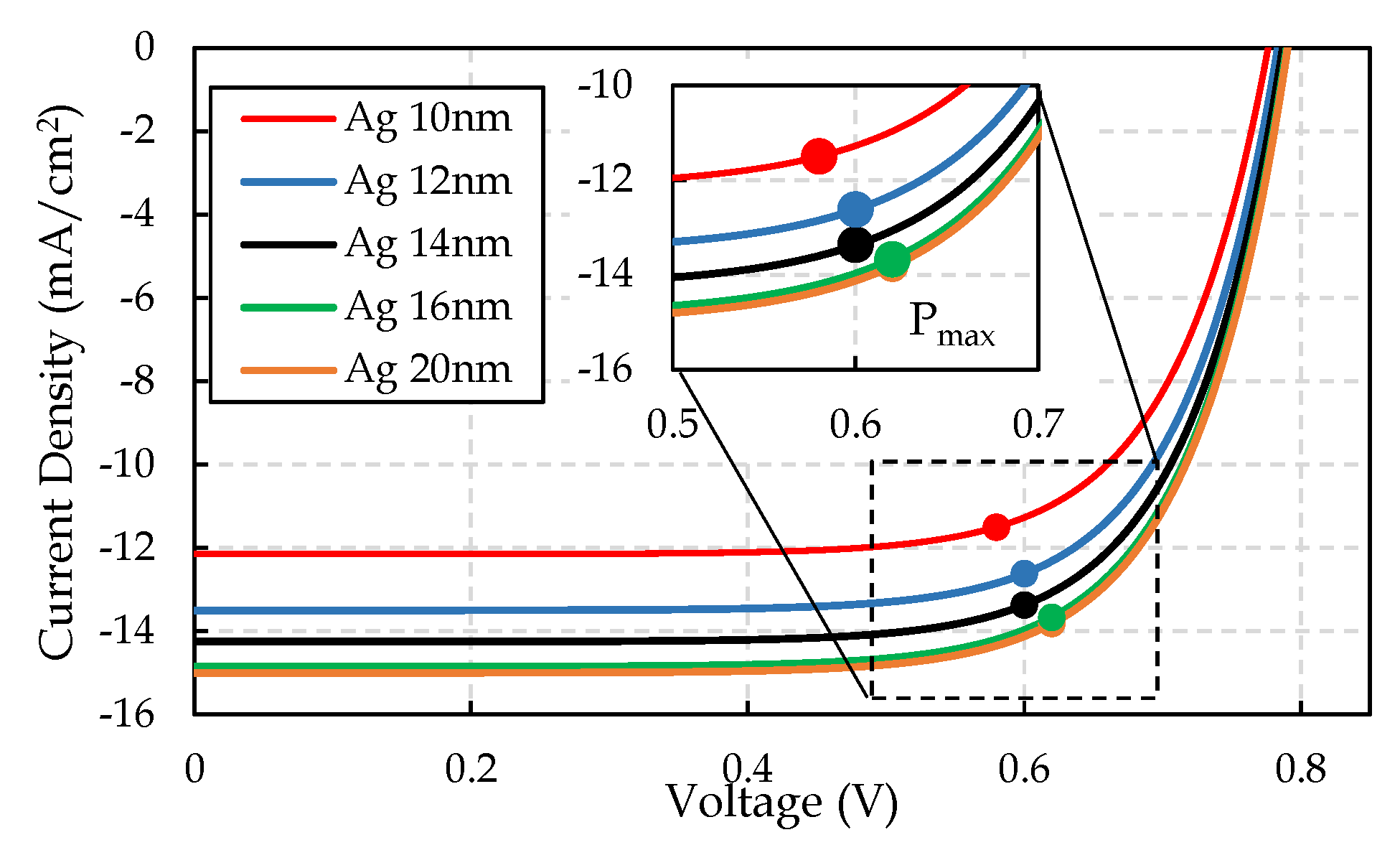
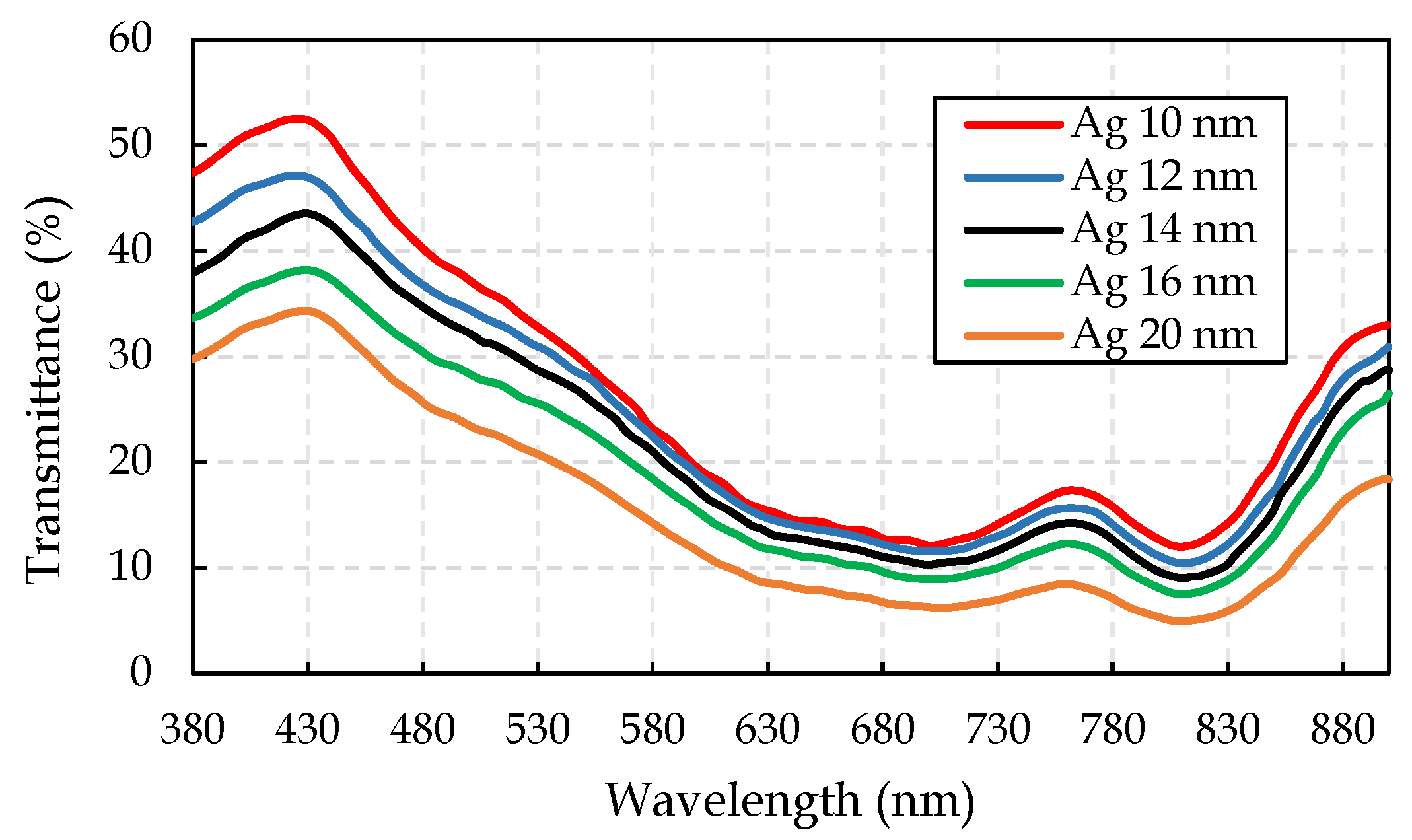
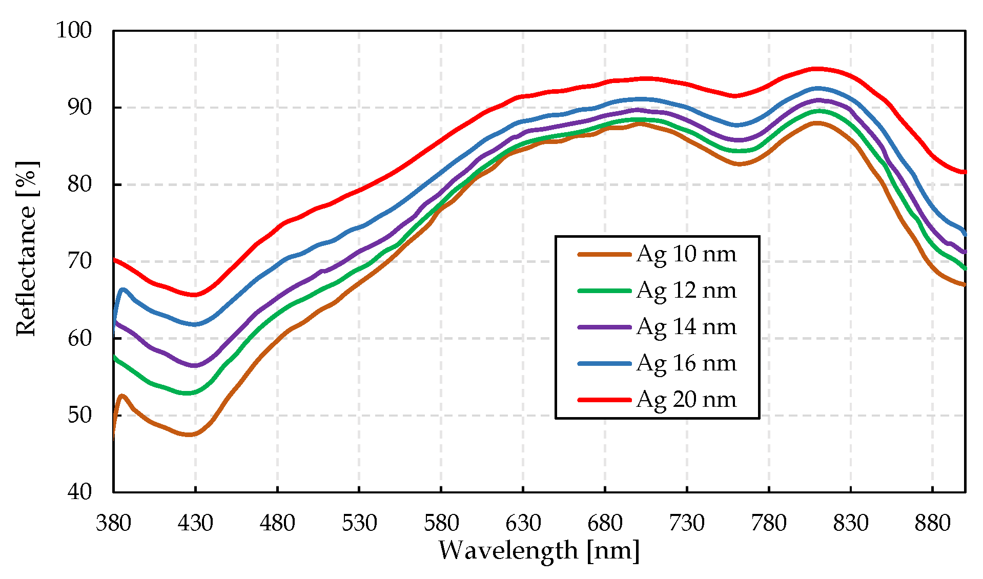
The photovoltaic and radiative properties of semitransparent organic photovoltaic (ST-OPV) materials must first be defined to model solar harvesting, and to evaluate the temperature behavior inside the analyzed thermal zone. Photovoltaic power assessment requires other data, such as the current and voltage produced by the ST-OPV device at each stage. These values were estimated on the basis of the solar irradiation on glazing available via weather files. Having the information from Table 1, and on the basis of Sun et al. [38], Figure 5 was constructed using the single-diode PV cell-equivalent circuit developed by Bellia et al. [39], Bayrakci et al. [40], Altas and Sharaf [41], and Duffie and Beckman [42]. The large dots indicate in detail the maximal power point for each silver substrate specimen labelled Ag 10 to 20 nm. Table 2 shows the results for the spectral average transmittance values calculated by mathematical integration for visible and total available spectrum pictured in Figure 6. Figure 7 also presents the reflectance for each silver substrate for the available spectrum.

2.8. ANSI/ASHRAE Standard 140-2011

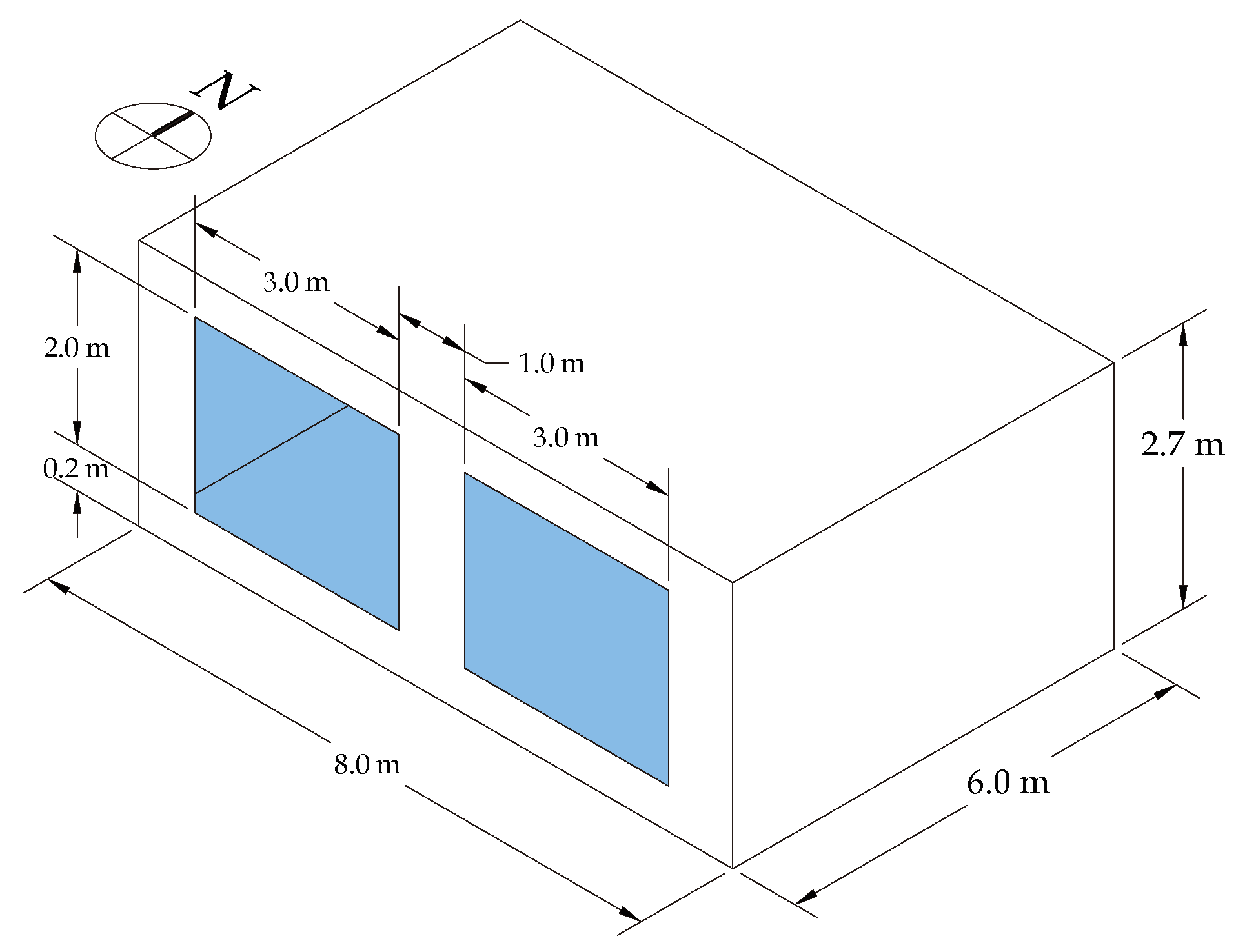
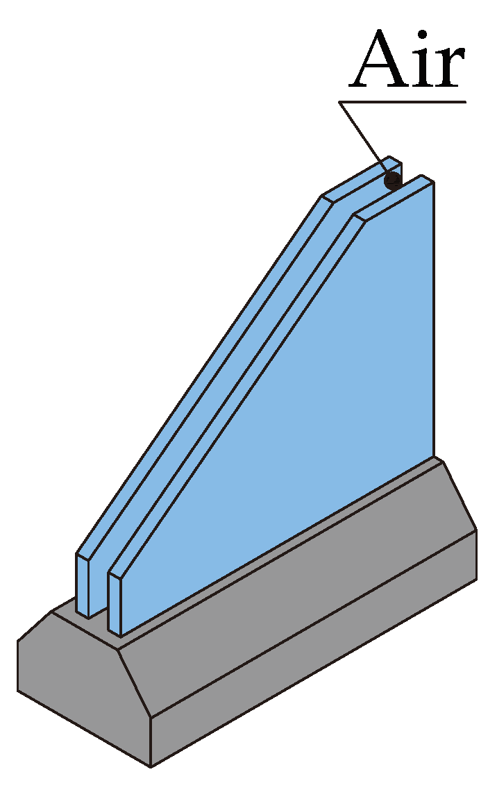
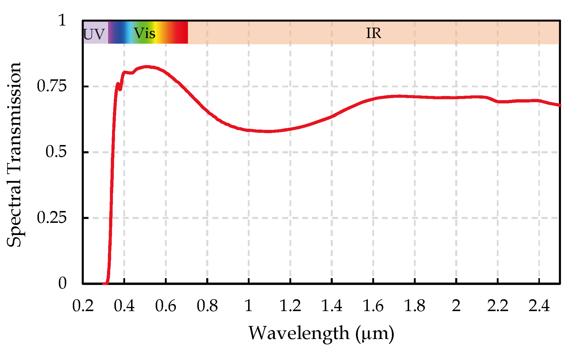
The basic test building (Figure 8) was a rectangular single zone (8 m wide × 6 m long × 2.7 m high) with no interior partitions and 12 m 2 of windows on the southern exposure. The building was of lightweight construction; other attributes are described below. For further details, refer to Section 5.2.1 of the ANSI/ASHRAE Standard 140-2011, Judkoff and Neymark [43]. Figure 9 shows a graphical representation of the BESTest glazing system, and Figure 10 shows the radiation transmitted by the glazing on the visible and infrared spectra. The thermophysical properties of the materials used for the model are listed in Table 3, which corresponds to standard low-mass enclosure settings. The BESTest methodology presented by Jorissen et al. [44] can also be used as a first test to verify possible code-related errors by comparing and checking if the results are somehow similar with the results obtained before implementation. Low-mass Case 600 FF was selected, as indoor temperature is more sensitive to the thermal performance of a glazing system. Table 4 shows the physical properties for windows or glazing.

2.9. Development of a Cosimulation Tool

The development of a cosimulation tool enabled us to test new algorithms to improve mathematical and physical modelling on existing simulation tools. As previously described, this study consists of the development of an FMU (Version 1.0) under FMI standard in Python. Regarding FMU, the mathematical model and internal solver were based on the finite-volume method, and took into account the transmission and absorption of solar radiation on glazing on the basis of multireflection, as previously introduced in Riquelme et al. [28] and applied in Riquelme et al. [45].

2.9.1. Whole-Building Hygrothermal Simulation Program DOMUS: Implementation

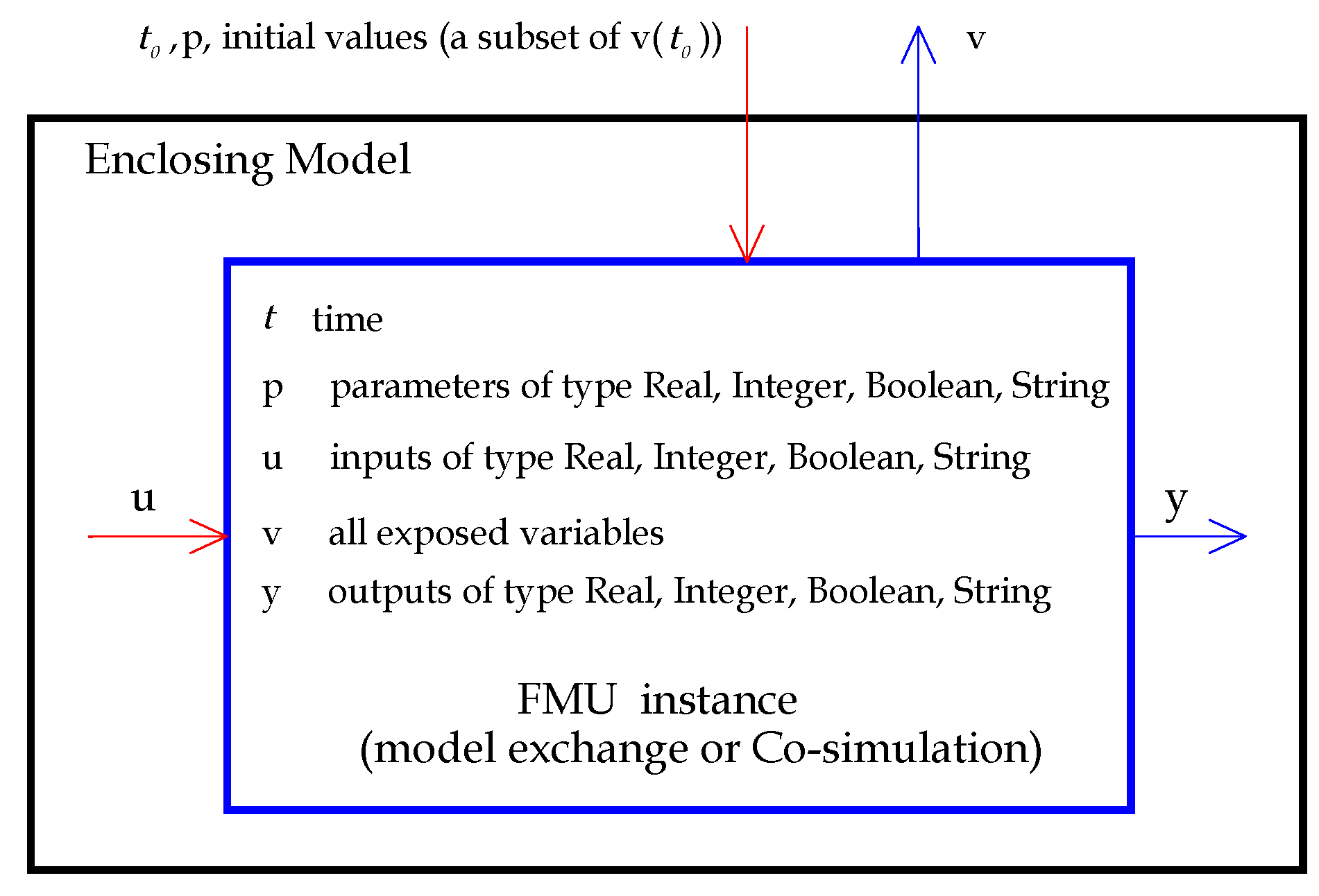
The implementation was performed using the FMI standard that defines a container and an interface to exchange dynamic models using a combination of XML files, binaries, and C code, distributed as a ZIP file. The ZIP file contained the FMI Description file (XML), the binaries and libraries required to execute the FMI functions (.dll or .so files), the sources of the FMI functions (optional), and other data used by the FMU. An FMU can hide the source code to secure the contained know-how or to allow for the fully automatic import of the FMU in another simulation environment. A schematic and general view of an FMU standard is shown in Figure 11 based on Blochwitz [46], where blue arrows denote the information provided by the FMU (Developed Python Solver), and the red arrows denote the information provided to the FMU (DOMUS data). All types of variables that can be used are presented here. In our case, the variables are all real numbers, t is the time step defined by DOMUS, u are the inputs as an external convective coefficient, internal convective coefficient, direct solar radiation, diffuse solar radiation, external temperature, internal temperature, p and v are the parameters and variables that include internal process as solar geometry, internal energy balance, angular radiative properties, and the radiative long-wave balance on the thermal zone. y are the outputs of the FMU that are the temperatures on the glazing system in our case.
To increase the speed and accuracy of assessment associated to direct solar radiation gains, a pixel counting technique was implemented in DOMUS, with an extensive validation presented in de Almeida et al. [47], and de Almeida et al. [48].

2.9.2. Scheme for Glazing Model

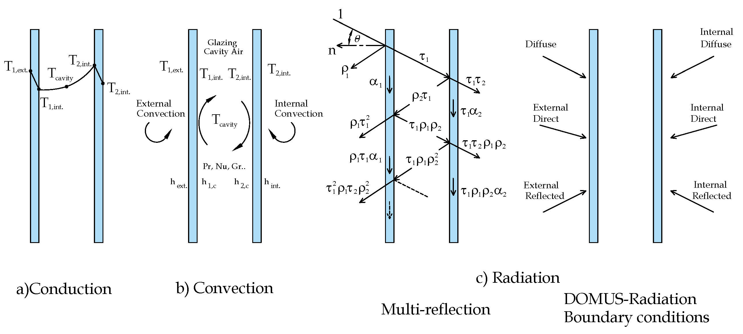
The tested model was a capacitive finite-volume (FV)-based model to implement a new technology not present in the Domus model. Figure 12 presents the different elements of the solver model based on the FV method by Patankar [49] to solve differential equations. These equations are solved via the tridiagonal matrix algorithm (TDMA), which considers heat transfer by conduction, forced external convection, free internal convection (vertical cavity between panes), and multireflection for glazing transmission with a fully implicit scheme.
Technology is not present in the DOMUS model, which also has a capacitive model, but is not prepared to simulate technologies such as the one based on STPV. Domus window model can be seen in Freire et al. [50].

3. Verification

As previously described, the FMU approach must be verified. The BESTest Case 600 FF was selected because a low-mass building coupled with an extensive glazing system can considerably affect internal temperature.

Domus Results for BESTest 600 FF

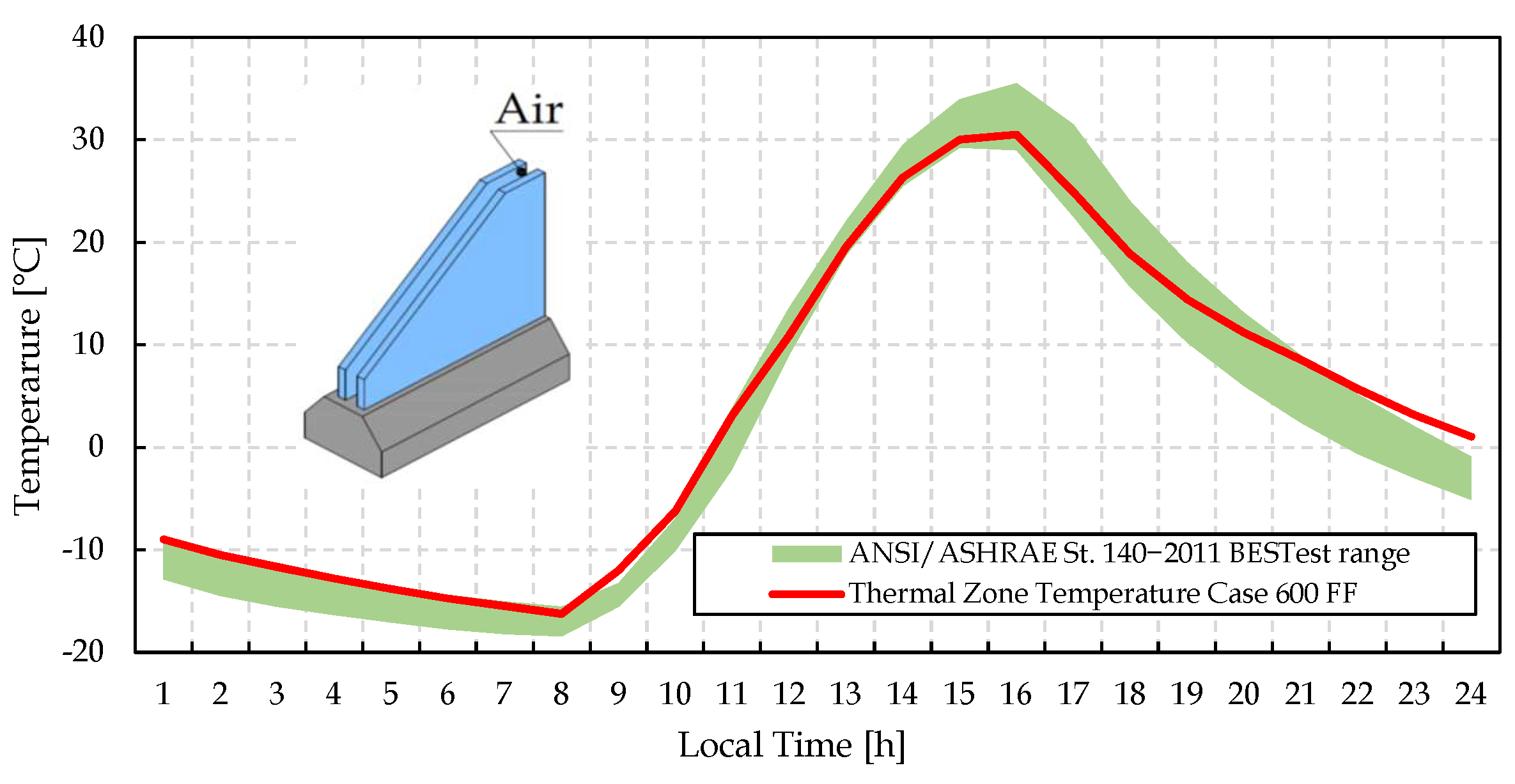
This section shows the results of the verification stage. Relevant data are displayed in the figures, including the main variables and their comparison with the available data. Figure 13 presents the results for the comparison of the thermal zone temperature obtained through the developed mathematical code and the available range results in the ANSI/ASHRAE Standard 140-2011 Judkoff and Neymark [43]. Results were aligned to the values set for a clear cold day. Figure 13 also indicates appropriate physical modelling through the numerical results. The BESTest Case 600 range was obtained by using steady-state based models, while the red line represents results gathered from simulations using a transient model.
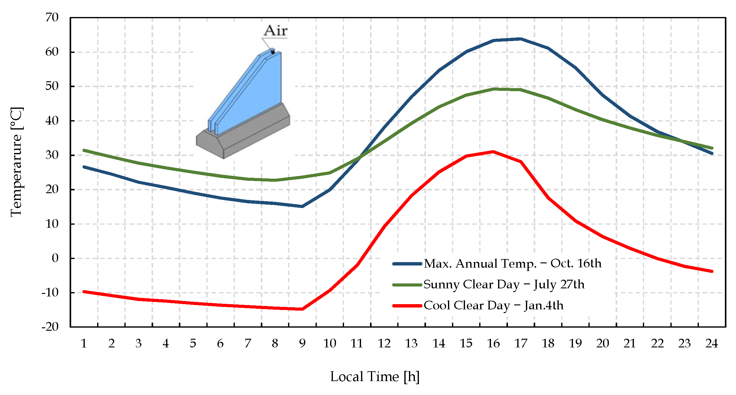
After this first stage, we were able to validate the mathematical code for the evaluation of glazing systems, and with it, to propose an approach to assess the photovoltaic potential in glazing with a semitransparent organic photovoltaic material. Figure 14 compares Domus-FMU and the BESTest validation reports Judkoff and Neymark [43], for the maximal annual temperature on 16 October, a sunny clear day on 27 July, and a cool clear day on 4 January, showing good consistency by the two models.

4. Results and Discussion

In this section, we present the results of numerical modelling and the application of a method to incorporate a semitransparent organic photovoltaic element to glazing. A typical integration is based on the previously detailed theoretical models. Current research on semitransparent elements with photovoltaic capacity shows promising results. In this study, our approach included organic elements, since they are state-of-the-art materials that showed near 10% efficiency rate in recent studies on OPV [9].

4.1. Approach of Integration Model for Estimating Photovoltaic Energy on a Glazing Facade

This section shows the results of a single thermal zone and glazing systems model that considers the spectral radiative properties and multireflections when integrating a semitransparent photovoltaic material in glazing for solar energy harvesting. First, the results for the thermal zone simulation consisted of a comparison between the thermal zone temperature obtained in BESTest with the temperature profiles obtained with the five different thickness values of the silver substrate, originally labelled Ag 10 Ag 20 nm, as per Sun et al. [38]. Lastly, we include the results for solar-energy harvesting using photovoltaic integration based on Clarke [36]. Figure 15 presents the temperature profile of the thermal zone according to the five selected ST-OPV settings. In this example, selected Case 600FF and a single-pane glazing with the integrated ST-OPV as a thin film over the external surface of the glazing with the internal pane as substrate follows the mathematical approach in Section Integration Photovoltaic Glazing in Buildings based on Thin Films. Figure 15 illustrates also the important reduction on the temperature peak values, as a second remarkable positive effect of ST-OPV systems.

4.2. Photovoltaic Modelling Results

This section presents the results for solar energy harvesting for the material under study in Figure 16. Our approach is similar to Clarke’s [36] in Equation (15) in that we estimated the energy that could be produced by the integration of ST-OPVs materials such as a thin film into the glazing. The results depict the southern façade over the course of four days (12 to 16 January). The solar energy harvesting in this case clearly followed the behavior of the available solar irradiance data defined by the BESTest dry-cold weather file. This may have been due to the fact that the generated current ( I g ) and node voltage ( V i ) produced by the device were only available as global values [38], and were directly related to the solar irradiation that reached the southern glazing at each stage. The maximal power generation reached 77 W in each glazing on 14 January, the equivalent to 9% efficiency. The model also allowed for us to input the value of the temperature at the node of the control volume equivalent to the position of the photovoltaic element. Therefore, we can evaluate the efficiency of these materials when this information becomes available in the future. Recent studies indicated that this material may reach near 18% efficiency [9], but the study did not report on the spectral transmission and provided no quantitative information on the temperature effect on efficiency.

5. Conclusions

Developing a physical and mathematical model to calculate energy production of glazing systems is not a simple task. We sought to relate factors such as spectral transmission, reflection, and multireflection, which could be approached in several ways, as shown in Rubin et al. [51], ISO 9050 [52], and Howell et al. [53]. These factors were considered as we developed a comprehensive transient model on the basis of the finite-volume method with an evaluation of heat transfer by conduction inside the glass panes, forced convection both outside and inside the thermal zone, free convection between the panes and the respective inclusion of solar radiation that is transmitted, reflected, and even absorbed in the medium for energy generation. Then, we introduced an approach to calculate the amount of solar energy that can be harvested from a façade by coupling a photovoltaic material to the glazing in the form of a thin film. This material adopted the spectral radiative properties available on Sun et al. [38], and we followed the detailed mathematical approach presented by Clarke [36]. The paper contributes to the building simulation community by providing a new approach to unsteadily simulate a photovoltaic glazing model, and highlights the advantage of using an FMU that could be coupled to any building simulation tool with flexibility to test different models without modifying the source code of the main software. Hence, this study sought to develop a mathematical code for the Domus program to enable the future evaluation of energy-generation capacity in facades and, more specifically, composed by glazing materials. Since this is part of the development stage, we decided to include a cosimulation tool so we could freely modify the mathematical model without having to reprogram and recompile the master program (Domus). The adopted methods in the verification stage were based on the ANSI/ASHRAE Standard 140-2011 Case 600 FF to evaluate the thermal behavior of a single thermal zone to test glazing systems with a large glazed area on the southern wall. In this case, the incident solar energy on this façade transmitted within the thermal zone produced a clear increase in room air temperature, as shown in Figure 13. The results for temperature are in the line with the BESTest range [43], which indicate the consistency of the developed FMU. As mentioned above, the developed model integrates the temperature of the node or area where the energy-generating material is located. When the performance information of these emerging materials is available, the real values of photovoltaic generation can improve the simulation. We may infer that there is a correlation between performance and the materials of the cells, namely, cadmium tellurium and silicon, which may be the subject of a future study. We also suggest that future research include the temperature dependence of the efficiency of those type of cells. The contribution is on the development of a new functional mock-up unit to cosimulate photovoltaic energy generation in glazing systems and the dissemination of such a technique, which greatly facilitates software development in collaboration with different partners without the need to modify and recompile the main program by means of an open-source program such as Python. The authors see it as a developing area where researchers can work focused only on their own model and not on the whole code, which may also stimulate cooperation with manufacturers. This study also contributes to the development of energy simulation models based on current cosimulation tools (FMI Standard) to integrate energy-generating elements to buildings involving new technologies and state-of-the-art research. Semitransparent organic photovoltaic materials strike a good balance between the advancement of simulation techniques and the speed of technological advancements. Lastly, this study may be considered to be a small contribution to the ongoing research on modern building façades.

Author Contributions

S.R. and A.G. drafted the concept of the manuscript. S.R. and B.K. collected data from the literature, drafted the manuscript, and prepared figures. L.M.M. and N.M. provided feedback and revision suggestions for the manuscript. All authors have read and agreed to the published version of the manuscript.

Funding

This research was funded by CNPq grants number 459149/2014-8 and 308398/2021-1.

Institutional Review Board Statement

Not applicable.

Informed Consent Statement

Not applicable.

Data Availability Statement

Not applicable.

Acknowledgments

The authors would like to thank the Brazilian agencies CAPES of the Ministry of Education, and CNPq of the Ministry of Science, Technology, and Innovation for the financial support given to the Thermal Systems Laboratory at PUC-PR. S. Riquelme would like to personally thank Universidad del Bio-Bio for the support to his PhD studies.

Conflicts of Interest

The authors declare no conflict of interest.

References

  1. Schweiger, G.; Eckerstorfer, L.; Hafner, I.; Fleischhacker, A.; Radl, J.; Glock, B.; Wastian, M.; Rößler, M.; Lettner, G.; Popper, N.; et al. Active consumer participation in smart energy systems. Energy Build. 2020, 227, 110359. [Google Scholar] [CrossRef]
  2. IEA. World Energy Outlook 2020. Available online: https://www.iea.org/reports/world-energy-outlook-2020 (accessed on 17 February 2022).
  3. Radulovic, J.; Skerlic, J.; Vaskovic, M.; Bojic, L. Building integrated photovoltaics. In Proceedings of the 13th International Quality Conference, Nicosia, Cyprus, 26–29 December 2019. [Google Scholar]
  4. Heinstein, P.; Ballif, C.; Perret-Aebi, L.-E. Building Integrated Photovoltaics (BIPV): Review, Potentials, Barriers and Myths. Green 2013, 3, 125–156. [Google Scholar] [CrossRef]
  5. Ordenes, M.; Marinoski, D.L.; Braun, P.; Rüther, R. The impact of building-integrated photovoltaics on the energy demand of multi-family dwellings in Brazil. Energy Build. 2007, 39, 629–642. [Google Scholar] [CrossRef]
  6. Joseph, B.; Pogrebnaya, T.; Kichonge, B. Semitransparent Building-Integrated Photovoltaic: Review on Energy Performance, Challenges, and Future Potential. Int. J. Photoenergy 2019, 2019, 5214150. [Google Scholar] [CrossRef] [Green Version]
  7. Shukla, A.K.; Sudhakar, K.; Baredar, P. Exergetic analysis of building integrated semitransparent photovoltaic module in clear sky condition at Bhopal India. Case Stud. Therm. Eng. 2016, 8, 142–151. [Google Scholar] [CrossRef] [Green Version]
  8. Stoichkov, V.; Sweet, T.K.; Jenkins, N.; Kettle, J. Studying the outdoor performance of organic building-integrated photovoltaics laminated to the cladding of a building prototype. Sol. Energy Mater. Sol. Cells 2019, 191, 356–364. [Google Scholar] [CrossRef]
  9. Cui, Y.; Yao, H.; Zhang, J.; Xian, K.; Zhang, T.; Hong, L.; Wang, Y.; Xu, Y.; Ma, K.; An, C.; et al. Single-Junction Organic Photovoltaic Cells with Approaching 18% Efficiency. Adv. Mater. 2020, 32, 1–7. [Google Scholar] [CrossRef] [PubMed]
  10. Schopp, N.; Brus, V.V. A Review on the Materials Science and Device Physics of Semitransparent Organic Photovoltaics. Energies 2022, 15, 4639. [Google Scholar] [CrossRef]
  11. Fritzson, P.; Aronsson, P.; Lundvall, H.; Nyström, K.; Pop, A.; Saldamli, L.; Broman, D. The OpenModelica Modeling, Simulation, and Development Environment. In Proceedings of the 46th Conference on Simulation and Modelling of the Scandinavian Simulation Society (SIMS2005), Trondheim, Norway, 13–14 October 2005; pp. 83–90. [Google Scholar]
  12. Wetter, M. Co-simulation of building energy and control systems with the Building Controls Virtual Test Bed. J. Build. Perform. Simul. 2011, 4, 185–203. [Google Scholar] [CrossRef] [Green Version]
  13. Wetter, M.; van Treeck, C. IEA EBC Annex 60: New Generation Computing Tools for Building and Community Energy Systems. Available online: https://www.iea-annex60.org/ (accessed on 18 September 2022).
  14. Crawley, D.B.; Pedersen, C.O.; Lawrie, L.K.; Winkelmann, F.C. Energyplus: Energy simulation program. ASHRAE J. 2000, 42, 49–56. [Google Scholar]
  15. MATLAB. Version 9.9.0 (R2020b); The MathWorks Inc.: Natick, MA, USA, 2020. [Google Scholar]
  16. Simulink. Simulation and Model-Based Design. Available online: https://www.mathworks.com/products/simulink.html (accessed on 18 September 2022).
  17. Modelica. The Modelica Association. Available online: https://modelica.org/ (accessed on 18 September 2022).
  18. Dymola. DYMOLA Systems Engineering. Multi-Engineering Modeling and Simulation based on Modelica and FMI. Available online: https://www.3ds.com/products-services/catia/products/dymola/key-advantages/ (accessed on 18 September 2022).
  19. Nouidui, T.; Wetter, M.; Zuo, W. Functional mock-up unit for co-simulation import in EnergyPlus. J. Build. Perform. Simul. 2014, 7, 192–202. [Google Scholar] [CrossRef]
  20. Python Software Foundation. Python. Available online: https://www.python.org/psf-landing/ (accessed on 18 September 2022).
  21. Mendes, N.; Oliveira, R.; Santos, G. DOMUS 2.0: A Whole-Building Hygrothermal Simulation Program. In Proceedings of the 8th IBPSA International Conference, Eindhoven, The Netherlands, 11–14 August 2003; pp. 863–870. [Google Scholar]
  22. Laouadi, A. Thermal performance modelling of complex fenestration systems. J. Build. Perform. Simul. 2009, 2, 189–207. [Google Scholar] [CrossRef]
  23. Eaton, J.W.; Bateman, D.; Hauberg, S.; Wehbring, R. GNU Octave Version 3.8.1 Manual: A High-Level Interactive Language for Numerical Computations; CreateSpace Independent Publishing Platform: Scotts Valley, CA, USA, 2014; ISBN 1441413006. Available online: http://www.gnu.org/software/octave/doc/interpreter/ (accessed on 18 September 2022).
  24. FMI Standard. Available online: https://fmi-standard.org/ (accessed on 18 September 2022).
  25. Modelisar Project. Available online: Http//www.modelisar.com (accessed on 17 February 2022).
  26. Simpack, 3ds. Available online: https://www.3ds.com/products-services/simulia/products/simpack/ (accessed on 17 February 2022).
  27. Available online: https://jmodelica.org/ (accessed on 17 February 2022).
  28. Riquelme, S.; Mendes, N.; Moura, L.M. An algorithm to determine radiative properties of glazing systems using simple window performance indicators. In Proceedings of the 24th ABCM International Congress of Mechanical Engineering, Curitiba, Brazil, 3–8 December 2017; pp. 1–12. [Google Scholar]
  29. Heavens, O. Optical Properties of Thin Solid Films; Dover Books on Physics Series; Dover Publications: Mineola, NY, USA, 1991. [Google Scholar]
  30. Schuster, C.S. Diffractive Optics for Thin-Film Silicon Solar Cells; Springer: Cham, Switzerland, 2017. [Google Scholar]
  31. Walton, G. Thermal analysis research program reference manual. National Bureau of Standards, United States; Department of Energy, Building Energy Sciences Branch, U.S. Department of Commerce, National Bureau of Standards: Washington, DC, USA, 1983; Volume 1, p. 296. [Google Scholar]
  32. Born, M.; Wolf, E. Principles of Optics: Electromagnetic Theory of Propagation, Interference and Diffraction of Light, 7th ed.; Cambridge University Press: Cambridge, UK, 1999. [Google Scholar]
  33. Gao, Q.; Wu, X.; Xia, Z.; Fan, Y. Coating mechanism and near-infrared reflectance property of hollow fly ash bead/TiO2 composite pigment. Powder Technol. 2017, 305, 433–439. [Google Scholar] [CrossRef]
  34. Rubin, M. Optical properties of soda lime silica glasses. Sol. Energy Mater. 1985, 12, 275–288. [Google Scholar] [CrossRef] [Green Version]
  35. Riquelme, S.; Mendes, N.; Moura, L. Determination of spectral optical constants of glazings by numerical integration from FTIR spectrometer measurements. In Proceedings of the 25th ABCM International Congress of Mechanical Engineering, Uberlândia, Brazil, 20–25 October 2019. [Google Scholar]
  36. Clarke, J. Energy Simulation in Building Design; Routledge: London, UK, 2007. [Google Scholar]
  37. Buresch, M. Photovoltaic Energy Systems: Design and Installation; McGraw-Hill: New York, NY, USA, 1983. [Google Scholar]
  38. Sun, C.; Xia, R.; Shi, H.; Yao, H.; Liu, X.; Hou, J.; Huang, F.; Yip, H.-L.; Cao, Y. Heat-Insulating Multifunctional Semitransparent Polymer Solar Cells. Joule 2018, 2, 1816–1826. [Google Scholar] [CrossRef] [Green Version]
  39. Bellia, H.; Youcef, R.; Fatima, M. A detailed modeling of photovoltaic module using MATLAB. NRIAG J. Astron. Geophys. 2014, 3, 53–61. [Google Scholar] [CrossRef] [Green Version]
  40. Bayrakci, M.; Choi, Y.; Brownson, J.R. Temperature Dependent Power Modeling of Photovoltaics. Energy Procedia 2014, 57, 745–754. [Google Scholar] [CrossRef] [Green Version]
  41. Altas, I.H.; Sharaf, A.M. A photovoltaic array simulation model for matlab-simulink GUI environment. In Proceedings of the 2007 International Conference on Clean Electrical Power, ICCEP ’07, Capri, Italy, 21–23 May 2007; pp. 341–345. [Google Scholar]
  42. Duffie, J.; Beckman, W. Solar Engineering of Thermal Processes; Wiley: Hoboken, NJ, USA, 2013. [Google Scholar]
  43. Judkoff, R.; Neymark, J. International Energy Agency Building Energy Simulation Test (BESTest) and Diagnostic Method; National Renewable Energy Lab. (NREL): Golden, CO, USA, 1995. [Google Scholar] [CrossRef] [Green Version]
  44. Jorissen, F.; Reynders, G.; Baetens, R.; Picard, D.; Saelens, D.; Helsen, L. Implementation and verification of the IDEAS building energy simulation library. J. Build. Perform. Simul. 2018, 11, 669–688. [Google Scholar] [CrossRef]
  45. Riquelme, S.; Mendes, N.; Moura, L.M. Validation and Application of a Numerical Code for Estimate Energy Performance of Complex Glazing Systems Based on Semi-transparent Organic Photovoltaics Elements. In Proceedings of the 16th IBPSA International Conference & Exhibition Building Simulation, Rome, Italy, 2–4 September 2019; pp. 4617–4624. [Google Scholar]
  46. Blochwitz, T.; Otter, M.; Akesson, J.; Arnold, M.; Clauss, C.; Elmqvist, H.; Friedrich, M.; Junghanns, A.; Mauss, J.; Neumerkel, D.; et al. Functional Mockup Interface 2.0: The Standard for Tool independent Exchange of Simulation Models. In Proceedings of the 9th International MODELICA Conference, Munich, Germany, 3–5 September 2012; pp. 173–184, ISBN 978-91-7519-826-2. [Google Scholar] [CrossRef] [Green Version]
  47. de Almeida Rocha, A.P.; Oliveira, R.C.L.F.; Mendes, N. Experimental validation and comparison of direct solar shading calculations within building energy simulation tools: Polygon clipping and pixel counting techniques. Sol. Energy 2017, 158, 462–473. [Google Scholar] [CrossRef]
  48. de Almeida Rocha, A.P.; Rodler, A.; Oliveira, R.C.L.F.; Virgone, J.; Mendes, N. A pixel counting technique for sun patch assessment within building enclosures. Sol. Energy 2019, 184, 173–186. [Google Scholar] [CrossRef]
  49. Patankar, S. Numerical Heat Transfer and Fluid Flow; CRC Press: Boca Raton, FL, USA, 1980. [Google Scholar]
  50. Freire, R.Z.; Mazuroski, W.; Abadie, M.O.; Mendes, N. Capacitive effect on the heat transfer through building glazing systems. Appl. Energy 2011, 88, 4310–4319. [Google Scholar] [CrossRef]
  51. Rubin, M.; von Rotay, K.; Powels, R. Windows optics. Sol. Energy 1998, 62, 149–161. [Google Scholar] [CrossRef]
  52. ISO 9050; Glass in Building-Determination of Light Transmittance, Solar Direct Transmittance, Total Solar Energy Transmittance, Ultraviolet Transmittance and Related Glazing Factors. 2003. Available online: https://www.iso.org/obp/ui/#iso:std:iso:9050:ed-2:v1:en (accessed on 17 February 2022).
  53. Howell, J.; Menguc, M.; Siegel, R. Thermal Radiation Heat Transfer, 5th ed.; CRC Press: Boca Raton, FL, USA, 2010. [Google Scholar]
Figure 1. Numerical cosimulation scheme.
Energies 16 00951 g001
Figure 2. Exchange of dynamical models following the functional mock-up Interface.
Energies 16 00951 g002
Figure 3. A cosimulation FMU and the connection to a tool for simulation.
Energies 16 00951 g003
Figure 4. Thin-film interaction.
Energies 16 00951 g004
Figure 5. Current density (mA/cm 2 ).
Energies 16 00951 g005
Figure 6. Transmittance—OPVs.
Energies 16 00951 g006
Figure 7. Reflectance—OPVs.
Energies 16 00951 g007
Figure 8. ANSI/ASHRAE 140/2011-Case 600/900.
Energies 16 00951 g008
Figure 9. BESTest defined glazing system.
Energies 16 00951 g009
Figure 10. Spectral transmission for a two-pane glazing system.
Energies 16 00951 g010
Figure 11. Data flow between the environment and an FMU.
Energies 16 00951 g011
Figure 12. Python Solver: graphical scheme model.
Energies 16 00951 g012
Figure 13. Standard 140-2011 hourly free float temperatures—clear cold day—Case 600FF..
Energies 16 00951 g013
Figure 14. Thermal zone temperature profile for maximal annual temperature, sunny clear day, and cool clear day.
Energies 16 00951 g014
Figure 15. Thermal zone temperature for selected ST-OPVs configuration due to base Case 600FF.
Energies 16 00951 g015
Figure 16. Estimated power generation on a ST-OPV-based glazing system.
Energies 16 00951 g016
Table 1. Photovoltaic parameters of organic cells with various Ag thicknesses under optimized conditions.
ClassEfficencyV oc J sc FF
%VmA/cm 2 %
Ag 106.80.8112.665
Ag 127.40.8113.566
Ag 147.90.8114.466
Ag 168.40.8115.466
Ag 209.00.8116.367
Table 2. Spectral average transmittance for ST-OPVs with various electrode thicknesses.
ClassVisibleTotal Spectrum
Ag 1033.6027.13
Ag 1230.5324.62
Ag 1428.8522.40
Ag 1623.6719.69
Ag 2019.4915.73
Table 3. Specifications of opaque surfaces.
SurfacesThicknessU-Value
(m)(W/m 2 K)
Walls0.0870.514
Roof0.1410.318
Floor1.2080.039
Table 4. Windows properties.
PropertyValue
Extinction coeff.0.0196 (1/mm)
Number of panes2
Pane thickness3.175 (mm)
Air-gap thickness13 (mm)
Index of refraction1.526
Transmittance one pane0.86156
Thermal conduc. glass1.06 (W/mK)
Conductance glass pane333 (W/m 2 K)
Exterior surf. coeff.21.00 (W/m 2 K)
Interior surf. coeff.8.29 (W/m 2 K)
Density of glass2500 (kg/m 3 )
Specific heat of glass750 (J/kg K)
Disclaimer/Publisher’s Note: The statements, opinions and data contained in all publications are solely those of the individual author(s) and contributor(s) and not of MDPI and/or the editor(s). MDPI and/or the editor(s) disclaim responsibility for any injury to people or property resulting from any ideas, methods, instructions or products referred to in the content.