Abstract
As a response to stricter exhaust emission regulations, an increasing number of diesel-powered ships are switching to liquefied natural gas (LNG) fuel or installing post-processing devices to reduce exhaust gas. However, these methods are not feasible for small ships operating primarily along the coast. This is because the cost of the exhaust gas post-processing devices is high, while a large-volume fuel system is required in the case of LNG. Thus, this study used a propane gas fuel system based on a 5.0 L gasoline engine for easy application to existing small ships without major modifications. To optimize the control according to changes in the fuel system, a 1D simulation was performed on the engine to be developed, and ignition timing optimization was investigated. In addition, fuel consumption was compared with that of a gasoline-based engine. The propane engine achieved over 95% power in comparison to a gasoline-based engine. During cold-start tests, starting performance at −15 °C was ensured. The purpose of this study is to provide guidelines to assist the development of LPG or propane engines based on gasoline engines through these processes.
1. Introduction
1.1. Background
Owing to global warming, polar ice caps are melting, sea levels are rising, and abnormal climate conditions, such as heavy rains and heat waves, are being observed; these phenomena have become a worldwide problem. The main cause of global warming is CO2, a greenhouse gas; an increase in CO2 concentration increases the temperature of the Earth owing to the greenhouse effect [1,2]. With industrial development, the number of vehicles and ships in operation has increased rapidly, and the transportation sector contributes approximately 20% of the total CO2 emissions [3]. Various countries across the globe are making concerted efforts to mitigate the problem of natural disasters caused by abnormal weather conditions owing to CO2 emissions. In light of these dire consequences, the Paris Agreement was adopted at the United Nations Climate Change Conference in 2015 [4,5]. Currently, approximately 200 countries have signed the Paris Agreement to reduce greenhouse gas emissions. In accordance with this greenhouse gas reduction commitment, the shipping sector is strengthening regulations on ship engine emissions. The International Maritime Organization (IMO), which manages international issues related to shipping and shipbuilding, has presented various scenarios for CO2 reduction [6,7] based on the 2008 CO2 emissions of 921 million tons. If no action is taken against the current CO2 emission trend, CO2 emissions are expected to reach approximately 1400 million tons per year by 2050. However, to mitigate global warming, more stringent regulations are required, and measures are being taken to limit the temperature rise to 2 or 1.5 °C by 2050. Initially, the IMO had set a plan to reduce emissions to half of the CO2 emissions recorded in 2008 by 2050. However, this strategy cannot limit the temperature rise to less than 2 °C by 2050. According to the IMO’s revised assessment, CO2 emissions must be zero by 2050 to limit temperature rise to within 2 °C; furthermore, CO2 emissions must be zero by 2040 to limit the temperature rise to within 1.5 °C. Therefore, to combat global warming, carbon neutrality will likely be brought forward, and regulations on CO2 emissions need to be gradually strengthened.
The IMO, a United Nations (UN)-affiliated organization for ship management, regulates NOx and Sox emissions. NOx is regulated by Tier I–III [8]. Figure 1a shows the NOx emission regulations according to engine operating conditions and Figure 1b shows the SOx emission reduction regulations. A total of 171 countries participate in the IMO emission regulations. The IMO designated an Emission Control Area to protect the marine environment and ecosystem, and applies stronger emission regulations depending on the region [9].
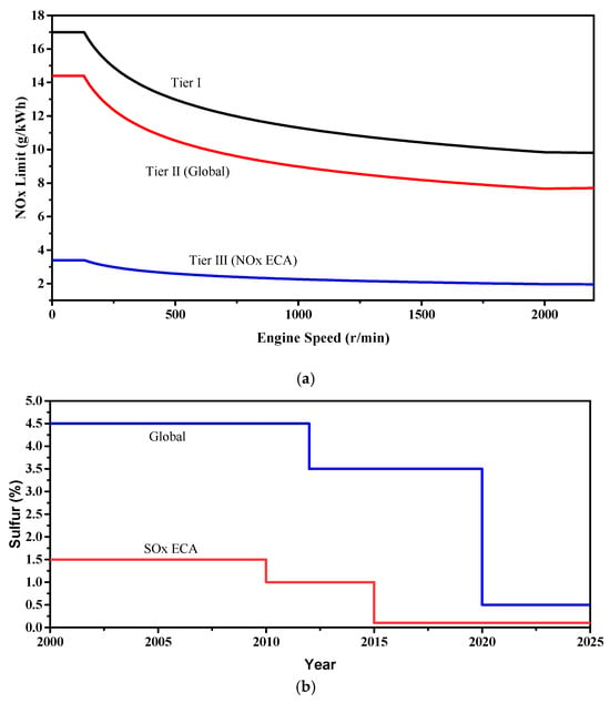
Figure 1.
(a) NOx emission regulations and (b) SOx regulations proposed by the IMO to reduce ship emissions.
1.2. Previous Studies
To respond to gradually stricter exhaust gas regulations owing to environmental problems, in the case of ships using diesel engines, various technologies, such as common rail direct injection variable valve timing and exhaust gas recirculation, have been proposed. Diesel particulate filters (DPFs), selective catalytic reduction (SCR), and SOx scrubbers have been applied to reduce particulate matter (PM), NOx, and SOx [10,11], essentially requiring after-treatment system installation and regeneration processes, such as DPFs, SCR, and SOx scrubbers, which are costly. To solve the problem of the increased complexity and cost of these systems, many scholars have investigated non-diesel alternative fuels like LPG, compressed natural gas (CNG), and liquefied natural gas (LNG) [12,13]. In particular, engines using LNG are gaining increasing attention as eco-friendly ship technology as they emit significantly less regulated substances, such as NOx, PM, SOx, and CO2, than diesel engines [14]. However, as LNG is liquefied below −196 °C, a system to re-liquefy the evaporated gas must be developed for efficient fuel use [15]. An LNG re-liquefaction system requires a large volume and weighs a lot; therefore, although it can be applied to large ships, it is not ideal for small ships operating primarily on the coast. Therefore, unlike existing LNG engines targeting large ships, this study investigated low-emission ship engines and targeted ships operating mainly along the coast. Contrary to LNG, where the size of the fuel system is large, liquefied petroleum gas (LPG) fuel systems are significantly more compact. Propane and butane, the main components of LPG, can be liquefied at 45 °C at 15 and 4 bar, respectively. Therefore, LPG fuel tanks can be miniaturized and applied to small ships [16]. Mahmud et al. studied a dual-fuel engine using both LPG and diesel to reduce exhaust emissions from a conventional marine engine using diesel fuel. Reportedly, by configuring the mixed fuel ratio of LPG and diesel as 80% and 20%, respectively, a reduction of 17% CO2, 12% NOx, 92% SOx, and 37% particulate matter compared with conventional diesel engines was achieved. In addition to reducing greenhouse and harmful gases, LPG has the advantage of reducing dependence on crude oil imports [17]. Yang et al. analyzed the types and availability of low- and zero-carbon fuels to reduce ship carbon emissions [18]. Currently, LNG, LPG, methanol, bio-diesel, hydrogen, and ammonia are considered alternative fuels for ships. Although hydrogen and ammonia are considered for ultimate zero carbon emissions, they need to be further investigated for use as alternative fuels owing to the difficulties related to their storage. Currently, LNG, the widely used fuel, is difficult to apply to small ships due to the large volume of the required fuel system and its low calorific value. Therefore, as an intermediate step before the ultimate carbon-neutral fuel is commercialized, an LPG engine was evaluated.
1.3. Research Purpose
To reduce the engine emissions of small ships sailing along the coast, the objective of this study was to modify the fuel system from a 5.0 L gasoline engine to propane, with a focus on control optimization and performance enhancement. A fuel supply system was constructed for the development of a marine propane engine. Research on ignition timing was conducted to optimize combustion for the modified fuel. Given the operational characteristics of marine engines, which often operate under high load conditions, ensuring engine output is crucial. Therefore, our goal was to achieve an output of over 90% compared to conventional gasoline engines. To prevent icing due to the vaporization heat of propane, a system capable of supplying fuel in gaseous form was constructed. In addition, to optimize the distribution and control of fuel supply, a gas injection system capable of injecting fuel into the intake port was developed. A 1D simulation was conducted before the experiment to predict the optimal ignition timing, fuel consumption, and power. In addition, various engine characteristics of the developed engine, such as power, fuel consumption, and exhaust temperature, were compared with those of gasoline-based engines, and the cold-start performance was determined by simulating a cold environment. The purpose of this paper is to provide guidelines based on this research process that can assist in the development of LPG or propane engines based on gasoline engines.
2. Experimental Setup
2.1. Engine Experiments
In this study, the fuel system of a gasoline engine was converted to a propane gas injection engine. The detailed specifications of the base engine are listed in Table 1. The base engine was a V8 with a displacement of 4966 cc. Note that the cooling systems of automobiles and marine engines are substantially different. Automobile engines use a radiator that cools the coolant with the driving wind, whereas marine engines cool the coolant with seawater through a heat exchanger. As a marine engine is installed in an enclosed space, high-temperature points should not be exposed to the outside of the engine to prevent fire or operator burns due to high temperature or fuel leakage. Therefore, the propane marine engine developed in this study was designed to cover the exhaust manifold surface to prevent hotspots from occurring outside the engine.

Table 1.
Specifications of the base engine used in this study.
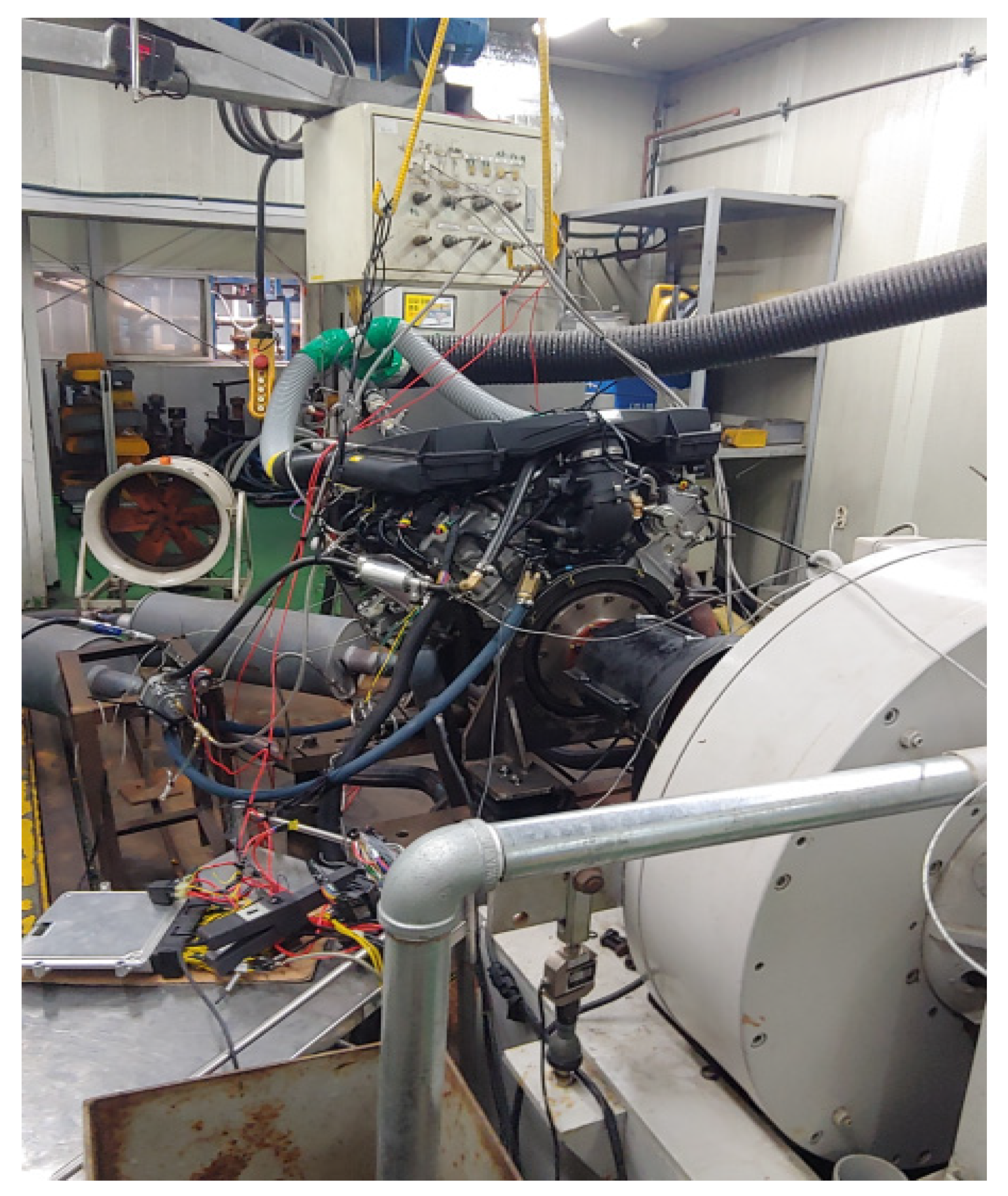
To measure the engine power, Fuchino’s 300 kW eddy current (EC)-type dynamometer was used, as shown in Figure 2. An EC dynamometer can measure the power of an engine and simulate various driving conditions by providing a load. The fuel consumption was measured by installing a flow meter in the fuel line, and MAX’s P213 piston-type flow meter with an accuracy of ±0.2% was used. The engine test was conducted at an intake temperature of 20 °C and an atmospheric pressure of 101.3 kPa.
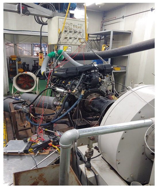
Figure 2.
The propane marine engine test cell used in this study.
In this study, the engine used was specifically designed for maritime vessels, with a cooling system distinct from that of land-based engines. Figure 3a provides a schematic diagram of the engine cooling system. The engine cooling mechanism employs a closed-loop coolant circuit, similar to conventional land-based engines. However, unlike typical land-based engines that use ambient air through a radiator for cooling, the marine engine utilized in this research utilizes seawater as a refrigerant and regulates the coolant temperature through a heat exchanger. Typically, V-type engines position heat exchangers on both sides, but the target development engine, taking future maintenance convenience into consideration, was configured with the heat exchanger positioned at the front, as depicted in Figure 3b.
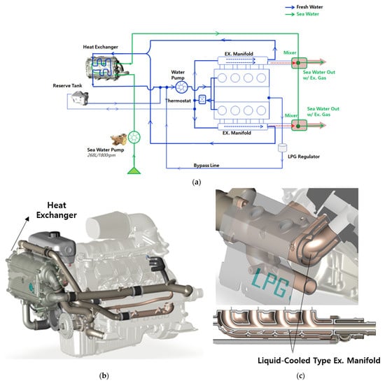
Figure 3.
Schematic diagram of the marine engine (a), location of the heat exchanger (b), and liquid-cooled-type exhaust manifold (c).
The engine room of a ship is often constrained by limited space, posing risks of overheating and potential fire hazards. To mitigate the risk of fires and comply with the safety standards for marine engines, the IMO provides regulations aimed at preventing engine room fires [19]. Hence, as shown in Figure 3c, to reduce the high temperature of the exhaust manifold surface, a liquid-cooled exhaust manifold was among the engine components, where the engine’s coolant was utilized to cool the exhaust manifold.
2.2. Fuel System
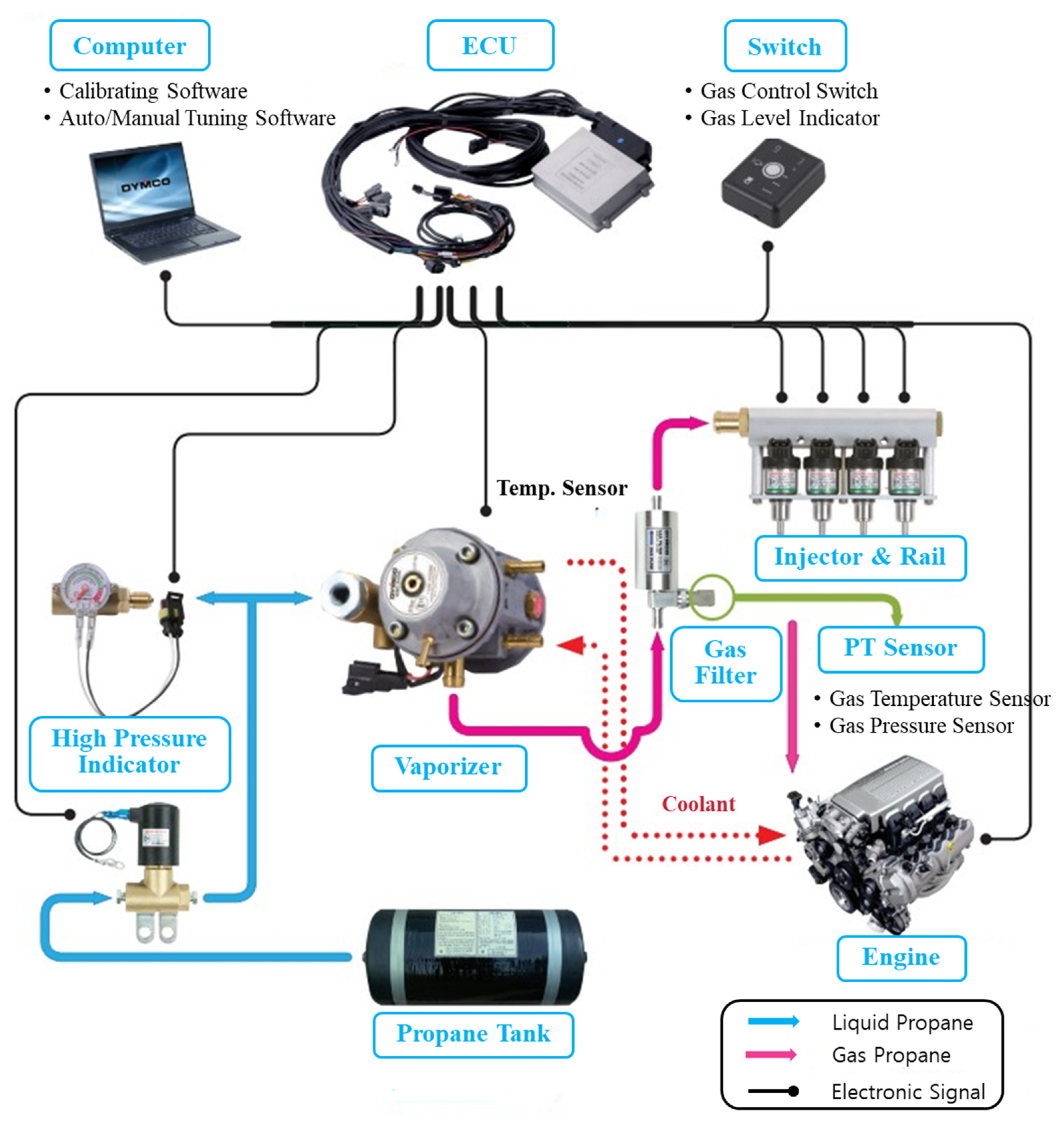
To convert the gasoline fuel system of the base engine into a propane fuel system, the system was configured as shown in Figure 4. Liquid propane was vaporized in the vaporizer and converted into gaseous propane. At this time, to prevent icing due to vaporization heat, the vaporizer was maintained at an appropriate temperature using the engine cooling water. Impurities such as tar were removed from the vaporized gas using a filter, and the gas was evenly distributed in each cylinder through a fuel rail. An injector was used to inject gaseous propane into the intake port at 1.3 bar. Unlike the general method of supplying vaporized propane to the mixer, a gas injector was used for independent injection into the intake port of each cylinder, enabling accurate fuel amount control and distribution. The injector was controlled to inject fuel at the proper time by sending a signal from the engine control unit (ECU) to the injector according to the valve timing. In this study, 100% propane was used as fuel. The detailed characteristics of propane are listed in Table 2. The research octane number (RON) of propane is extremely high (112), and the fuel can be predicted to have an exceptional knocking resistance. To liquefy propane, a temperature of −42 °C or pressure of approximately 15 bar is required, at which time its volume is reduced to 1/270. Compared with LNG, it is advantageous for application to small vessels as it can be liquefied relatively easily.
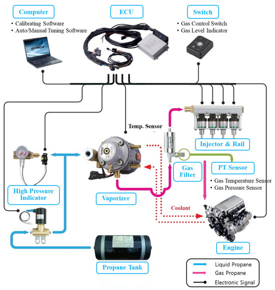
Figure 4.
Schematic of a gas-injection-type propane fuel system.
Table 2.
Propane physical properties.
2.3. Simulation Model
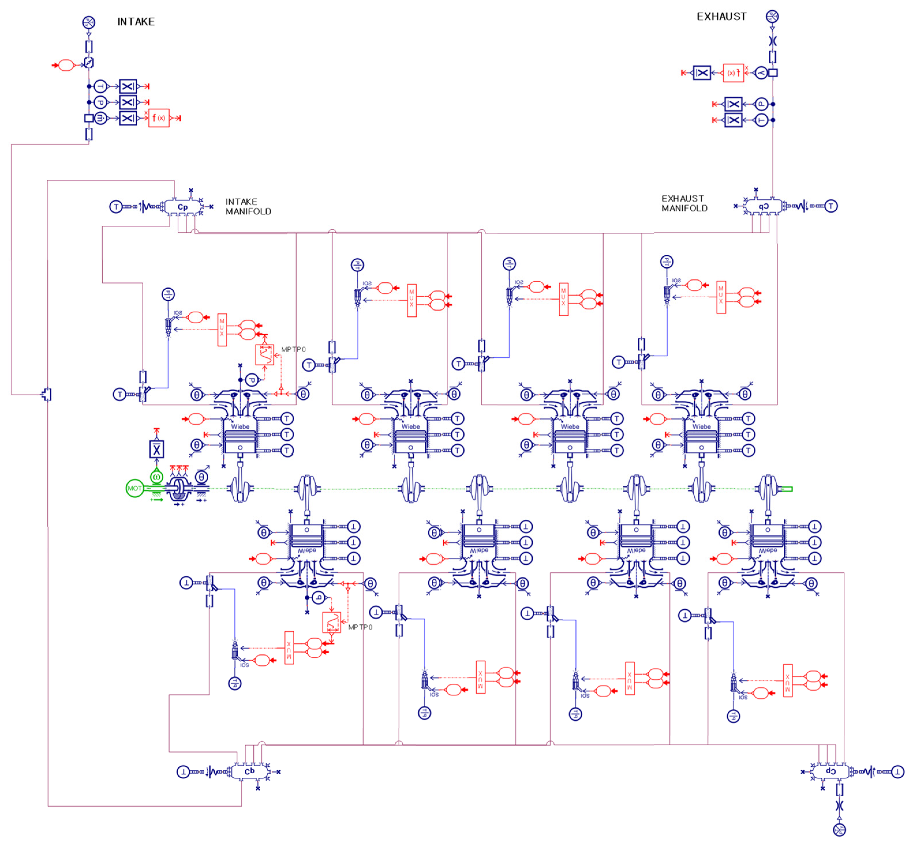
One-dimensional simulation is an efficient method for analyzing complex systems composed of various components. In this study, the Siemens advanced modeling environment for the simulation of engineering systems (AMESim) program was used for 1D simulation. AMESim specializes in analyzing various systems, such as mechanical, electrical, hydraulic, and pneumatic, and it can predict actual phenomena with high accuracy. It provides numerous libraries related to vehicles, including those of internal combustion engines, vehicles, transmissions, and cooling systems. Various studies on fuel economy, cooling performance, and exhaust gas have been conducted. In this study, a 1D simulation was used to determine the optimum ignition timing. Using only experimental methods to investigate ignition timing consumes considerable time and incurs high costs. An engine can be developed efficiently based on preliminary research conducted using a validated 1D simulation model. The first stage of the research process using 1D simulation is the accurate simulation and validation of the engine to be developed. Herein, the shape of the combustion chamber, intake and exhaust system, and the chemical characteristics and air–fuel ratio for the engine to be developed were first determined. Next, validation was performed based on the completed 1D simulation model to ensure the reliability of the model, and then the simulation was conducted. The optimal operating conditions were obtained by determining the crank angle point at which the brake torque is maximized at various ignition timings. Subsequently, engine operating conditions and characteristics at that time were analyzed. Figure 5 shows a 1D simulation of the engine to be developed. Gaseous fuel was injected into the intake port through the injector model; therefore, the vaporizer in the actual propane fuel system was omitted from the 1D model. A dynamometer model was used to adjust the load of the engine to simulate various operating conditions. The initial condition of the simulation model was 20 °C and 101.3 kPa. Furthermore, the throttle body component opening degree was configured to increase the intake airflow, allowing for the control of the engine power as it increases. In this study, the Wiebe combustion model was used. The combustion in an engine indicates the heat release rate from the start of ignition up to the charge extinction. This combustion model is based on the Wiebe Myamoto expression for combustion heat release. The Wiebe combustion model can be expressed as Equation (1). The Wiebe function estimates the mass fraction burned as a function of engine position. The start angle of the mass fraction burned was θ0, and the combustion duration was Δθ. The Wiebe parameters a and m determine the curve of the Wiebe function.
where
;
;
;
.
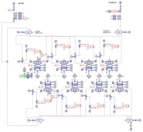
Figure 5.
One-dimensional simulation model that simulates the 5.0 L V8 engine used in this study.
Figure 5.
One-dimensional simulation model that simulates the 5.0 L V8 engine used in this study.
3. Results and Discussion
3.1. Simulation Model Validation and Results
As this study was aimed at developing a propane engine by modifying the fuel injection system of a base engine, an accurate understanding of the base engine is important. In particular, accurate validation of the base engine is essential for simulation. To simulate the base engine using a 1D simulation, a simulation model was constructed based on the exact specifications of the base engine, as shown in Figure 6. Based on the bore and stroke values of the specifications, the swept volume per stroke of the engine to be developed was calculated. The compression ratio was calculated using the volume of the combustion chamber when the piston is at the top dead center (TDC). The swept volume is expressed as follows:
where
;
;
.
The combustion chamber shape and engine efficiency were calculated based on values such as the squish area and piston offset.
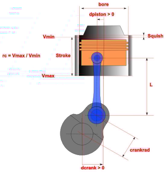
Figure 6.
One-dimensional simulation model based on the specifications of the engine to be developed.
Figure 6.
One-dimensional simulation model based on the specifications of the engine to be developed.

The 1D simulation was performed to analyze the influence of each component of the system to be developed using formulae. Therefore, to increase the accuracy of the simulation model, validation should be performed based on experimental data. Based on the experimental results of the base engine, the simulation model was validated to increase the accuracy of the simulation. The 1D simulation was used to analyze engine power, fuel consumption, and ignition timing for optimal combustion control. The brake mean effective pressure (BMEP) was validated to simulate the mean effective pressure generated during combustion in the engine. BMEP is calculated using brake torque measured with a dynamometer as in Equation (3).
engine torque;
: displacement volume;
number of revolutions per cycle.
To simulate the engine fuel consumption, the brake-specific fuel consumption (BSFC) was validated. BSFC, which means fuel consumption per unit of power, was calculated according to Equation (4) based on the fuel flow rate measured by the flow meter.
where
fuel mass flow rate;
engine torque;
engine speed in radians per second.
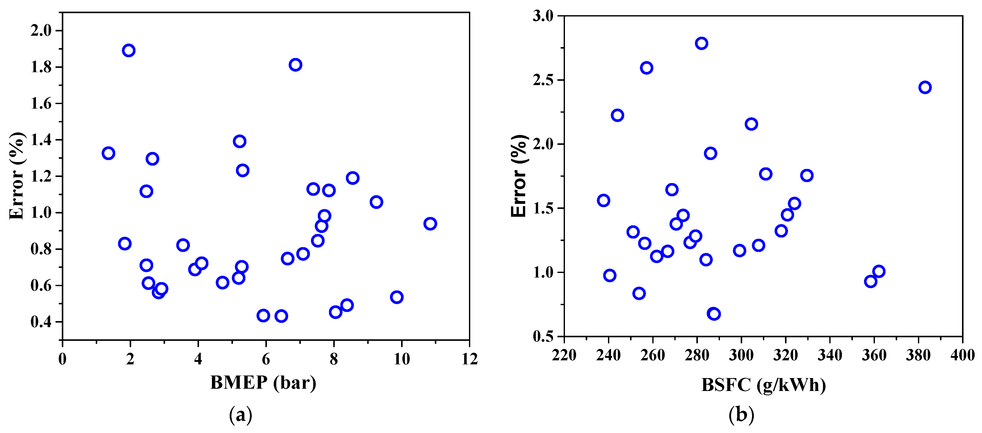
Figure 7 shows the comparison of simulation results corresponding to various operating conditions of the base engine with the experimental results. The relative errors between the experimental and simulation results for the BMEP, BSFC, and ignition timing of the base engine are shown in each graph. The average error values of BMEP and BSFC were less than 0.89% and 1.17%, respectively. Overall, the model exhibited errors of less than 1%; thus, in conclusion, the 1D simulation model was accurately validated.
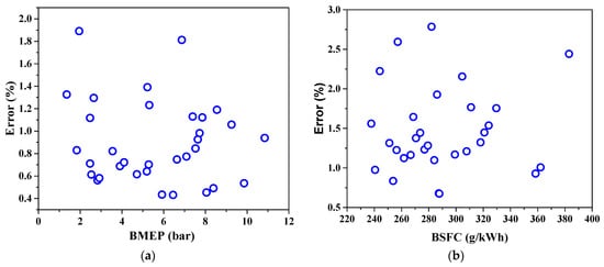
Figure 7.
Base engine validation under steady-state conditions: (a) BMEP error; (b) BSFC error.
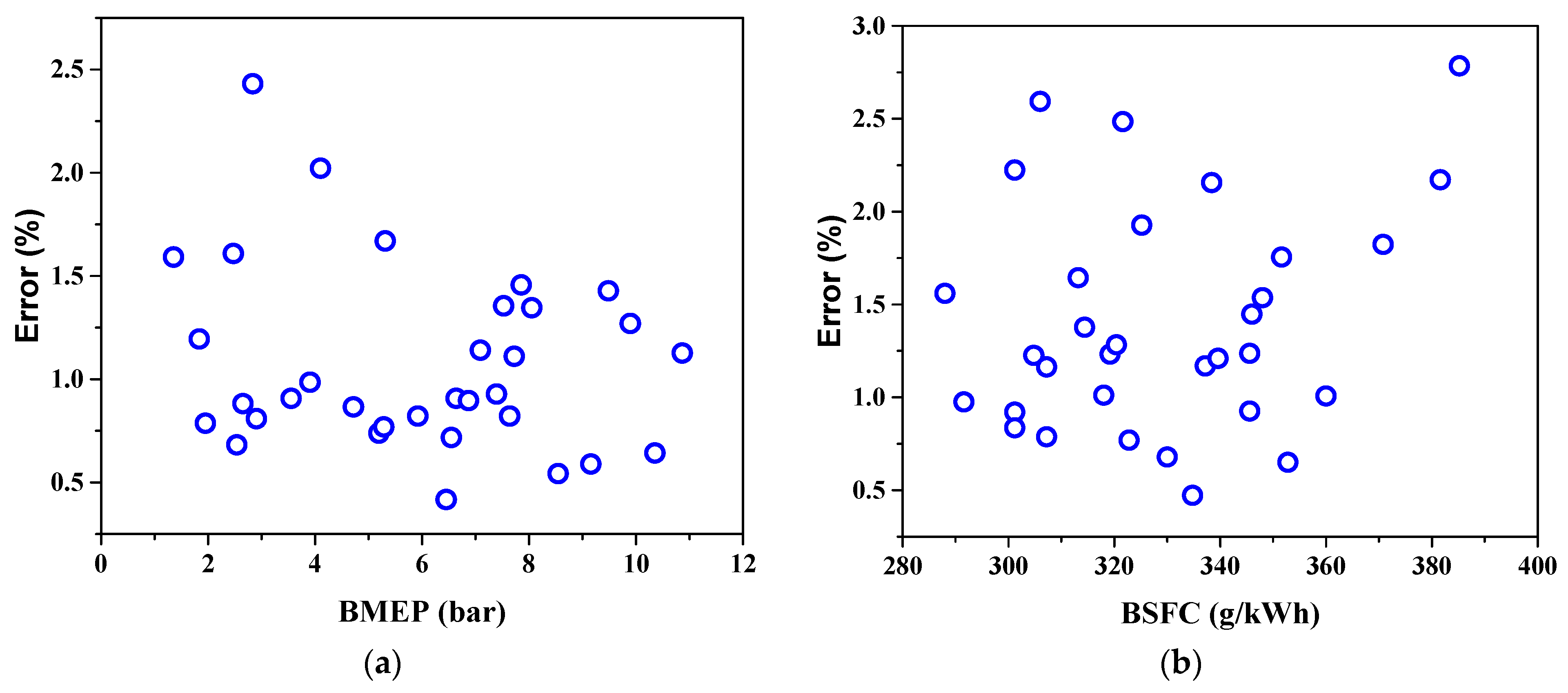
Based on the performance test results of a gasoline engine, the accuracy of the simulation model was confirmed to be high. The validation of the 1D simulation model confirmed a low error rate. Based on the simulation model of the validated base engine, the gasoline fuel system of the engine was converted to a propane fuel system, and a simulation was conducted. The experiments on BMEP and BSFC were conducted while varying the engine speed and load of the propane engine. The experimental and simulation results were compared, as shown in Figure 8. The error rates between the simulation and experimental results were 1.1% and 1.4% for BMEP and BSFC, respectively.
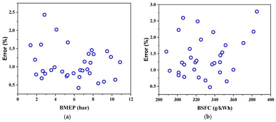
Figure 8.
Propane engine validation under steady-state conditions: (a) BMEP error; (b) BSFC error.
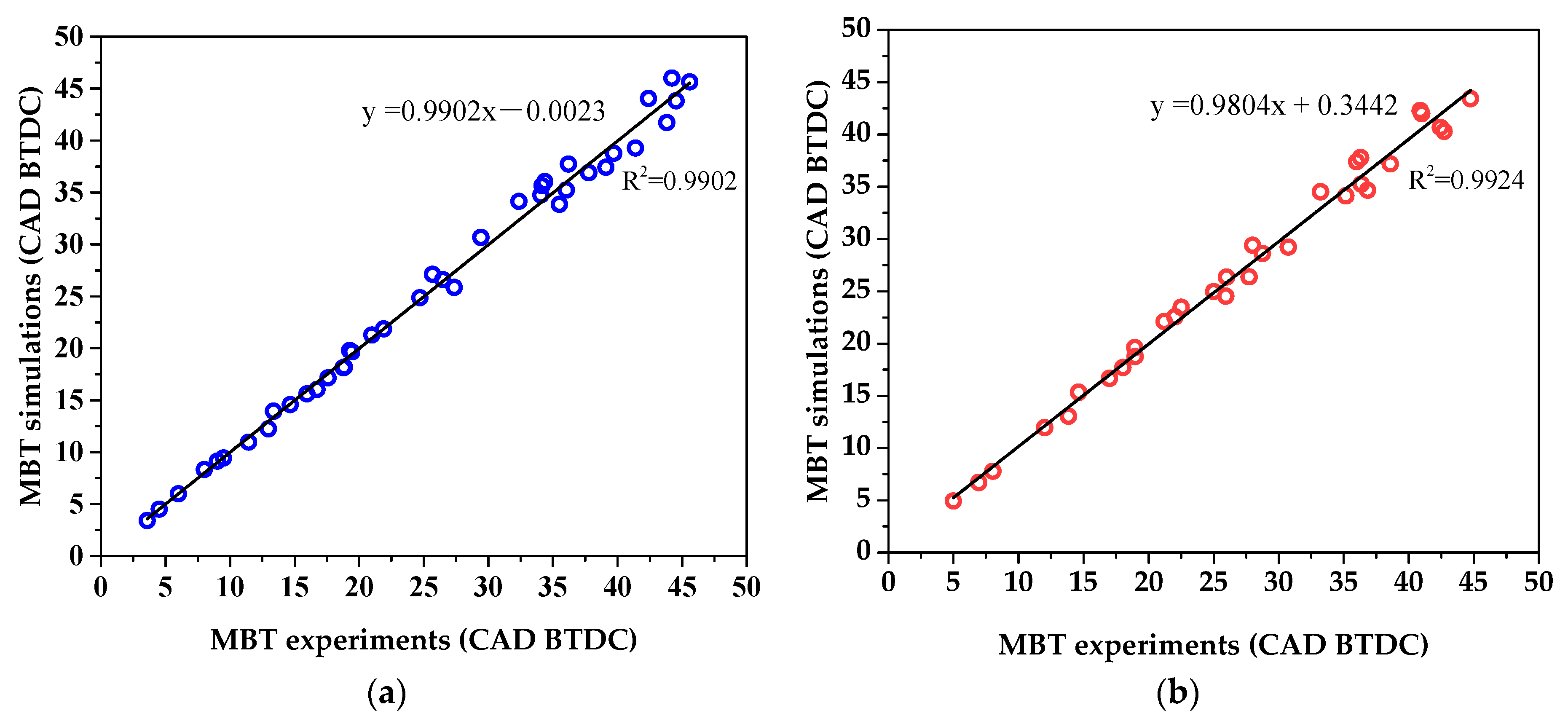
The combustion optimization was investigated using simulations while adjusting the ignition timing for load conditions corresponding to various engine revolutions. The ignition timing that maximized the propane engine efficiency was determined using the batch-study function of the Amesim simulation program, and the optimal ignition timing was derived for various operating conditions. Batch study can automatically repeat simulations by changing various variables or setting various operating conditions to analyze various cases. The function is efficient in that it captures the influence of various variables in a single operation. In particular, while investigating the optimal minimum spark advance for the best torque (MBT), which is the optimal ignition timing for maximizing engine torque, the effect of each ignition timing can be identified. Based on the simulation results, combustion optimization was investigated through an engine experiment. The comparison between the MBT of the actual engine and the simulation results is depicted in Figure 9. For both the gasoline and the propane engine, the R-squared values for the comparison between the experimental and simulation data exceeded 0.99. Therefore, through the simulation study on MBT, a significant reduction in the time and cost required for research was achieved.
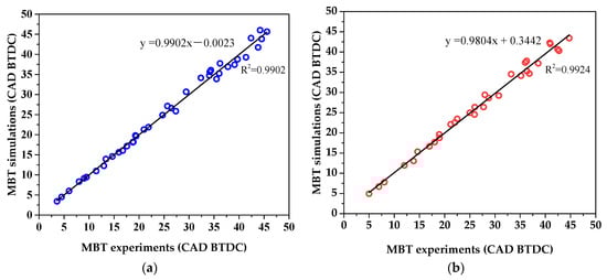
Figure 9.
Comparison of simulation and experimental results for MBT in (a) the gasoline and (b) the propane engine.
3.2. Engine Experiment Results
3.2.1. Ignition Timing Optimization
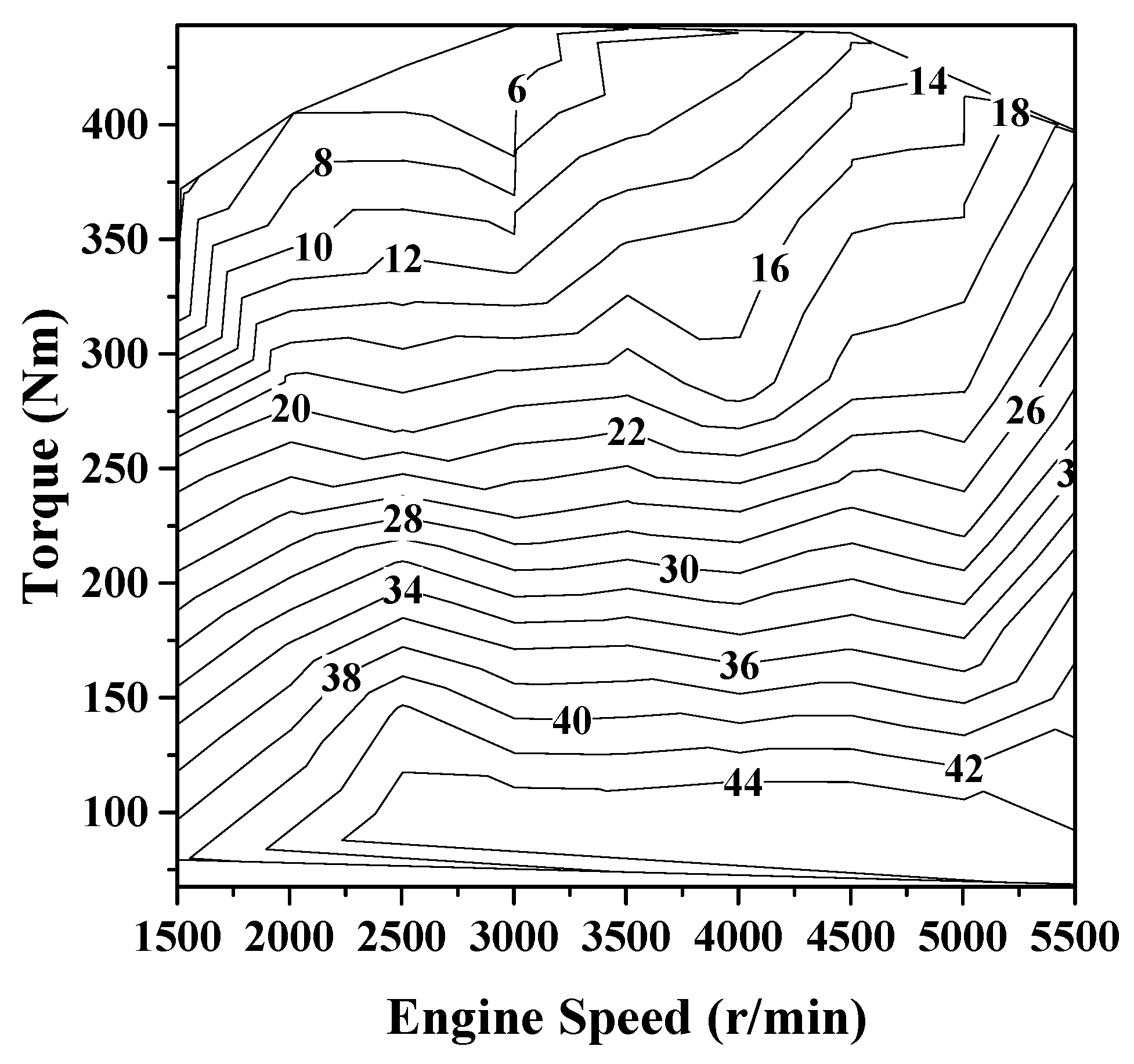
The ignition timing of an ignition (SI) engine is closely related to its thermal efficiency [20]. If the ignition timing is significantly advanced, the maximum pressure is reached before the TDC, which reduces thermal efficiency. Conversely, if the ignition timing is retarded, the ignition is delayed, and the effective work of the expansion stroke decreases, resulting in lower thermal efficiency. Therefore, determining the optimal ignition timing, called the MBT point, is crucial. Figure 10 shows the ignition timing map according to engine speed and load of the gasoline base engine. This result depicts the ignition timing that generates optimal efficiency based on engine speed and load conditions. When the throttle body opening is small, the airflow speed is low, and the flame propagation speed is low. Therefore, under low-load operating conditions, the ignition timing was advanced for ignition at 44° BTDC for maximum efficiency. However, under high-load conditions, the efficiency was maximized through a strategy of retarding the ignition timing with BTDC 6°. Thus, it can be observed that the ignition timing of the gasoline-based engine ranges from BTDC 44° to BTDC 6° depending on the operating conditions.
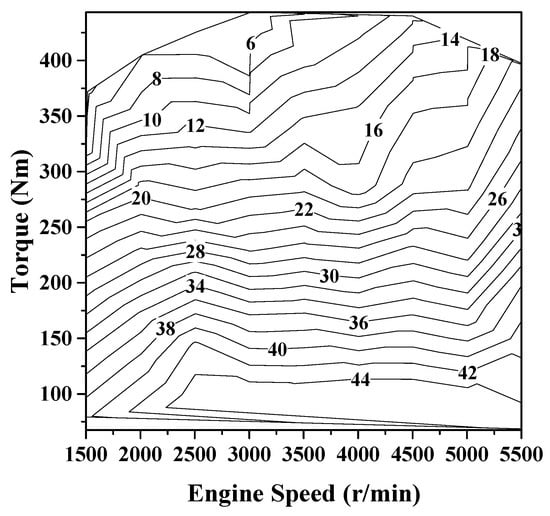
Figure 10.
Optimal ignition timing map of the base engine.
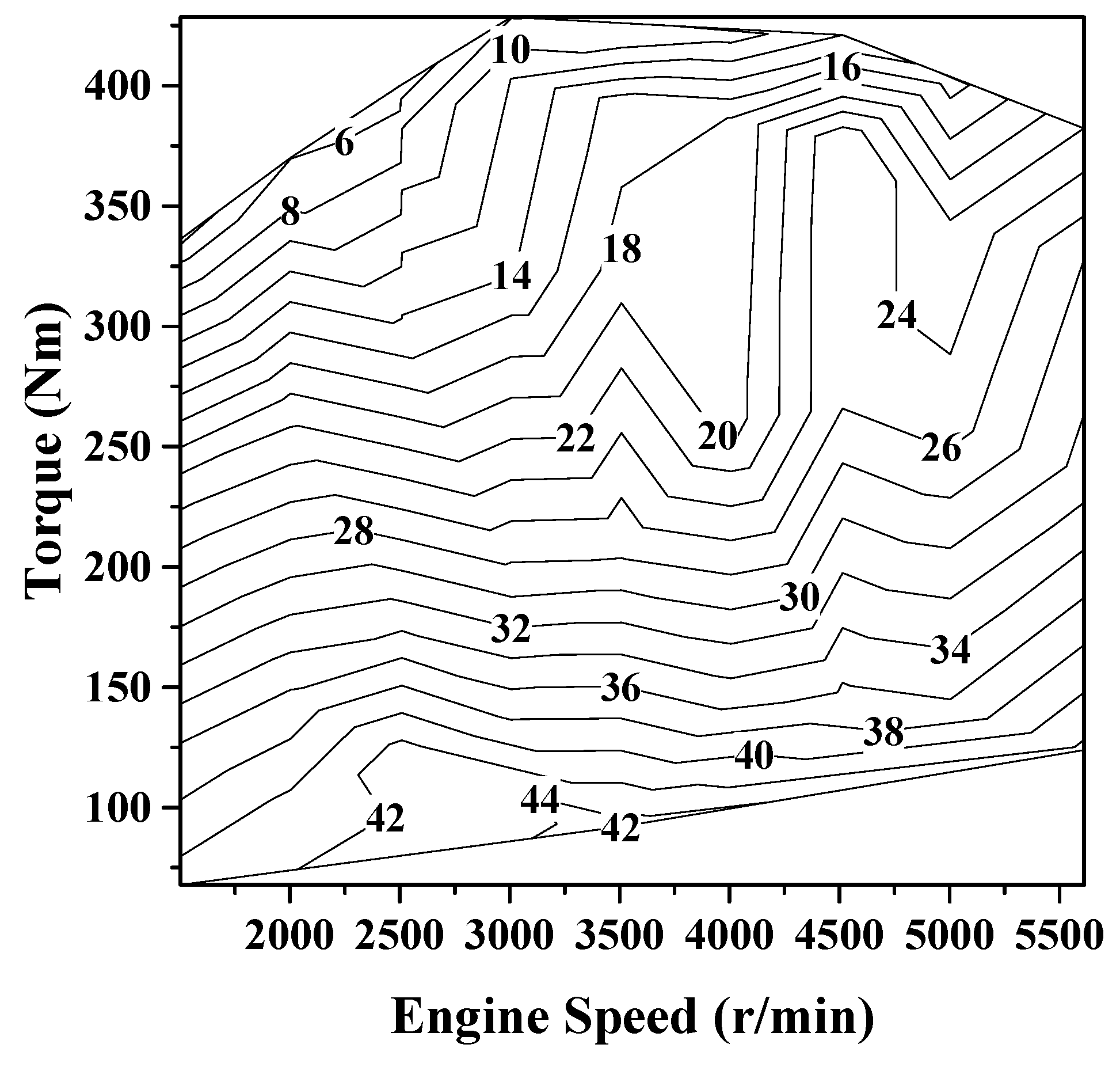
Based on the high accuracy of the validated 1D simulation results, the MBT point—the optimal ignition timing of the propane engine—was further investigated to derive the optimal ignition timing corresponding to various operating conditions and reduce the fuel system development time. Figure 11 shows the optimal ignition timing results corresponding to the engine speed and load of the propane engine. It represents an MBT ignition timing map for a propane engine, which was verified through experiments after conducting analytical research on the optimal ignition timing using 1D simulation. Under low-load conditions, ignition occurred at 44° BTDC, and ignition timing was delayed by up to 6° under high-load conditions. The difference between the ignition timings of the gasoline-based and propane-based engines is noticeable under high-load conditions. In the gasoline-based engine, the ignition timing was controlled at 6° BTDC for knocking control under 4000 rpm full-load driving conditions, whereas the propane engine was controlled at 10° BTDC under the same driving conditions. The gas fuel used in this study was composed of 100% propane with an octane number of 112, which is higher than that of mid-grade gasoline (89); therefore, it exhibits excellent knocking resistance [21]. Accordingly, compared to the gasoline engine, the ignition timing of the propane engine can be advanced under high-load conditions. Compared to a gasoline engine, the advanced ignition timing of the propane engine contributes to improved thermal efficiency and enhanced power.
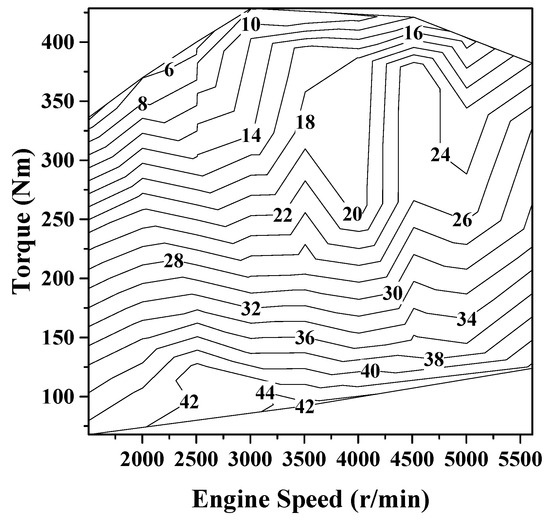
Figure 11.
Optimal ignition timing map of the propane engine.
3.2.2. Comparison of Engine Performance
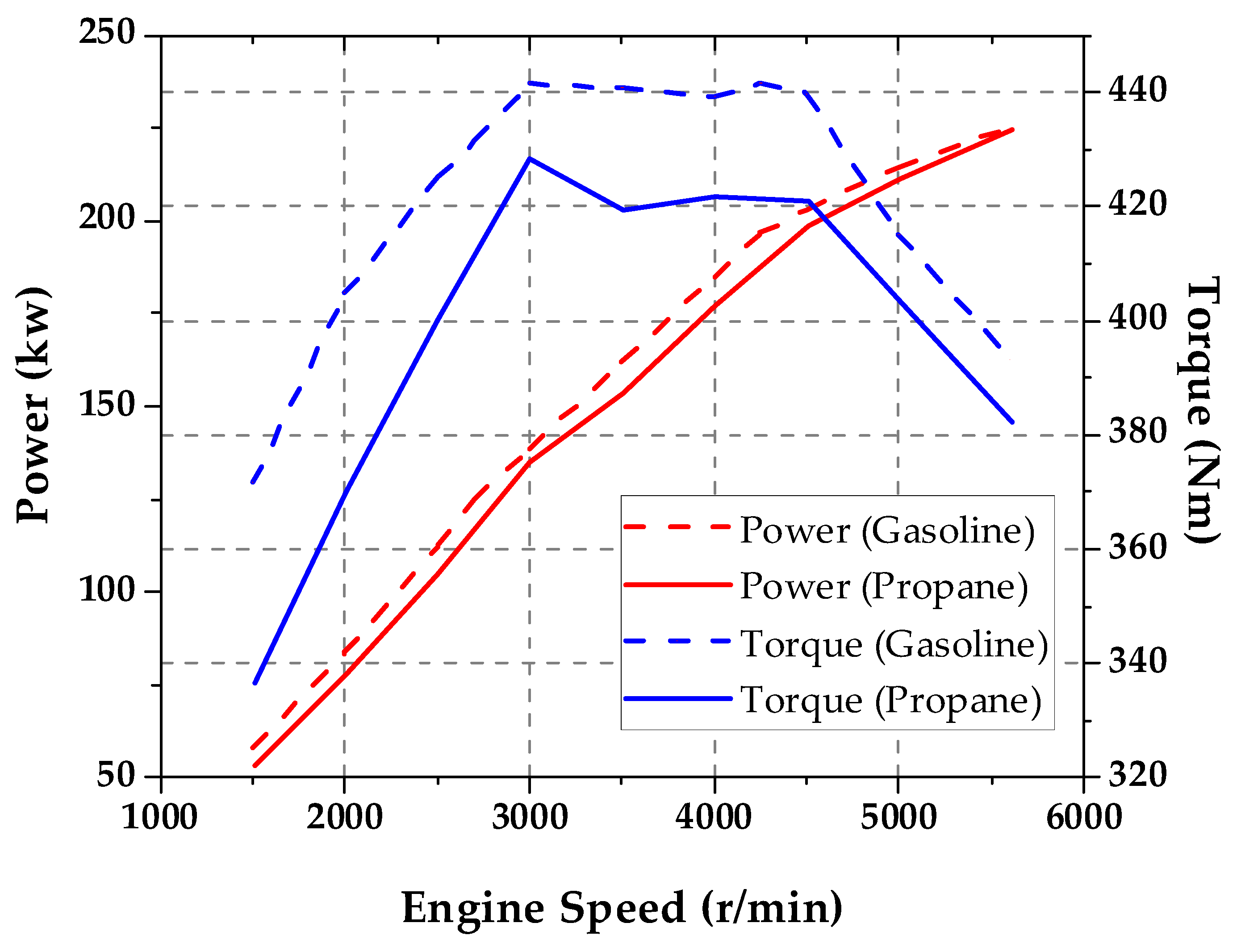
Figure 12 shows the performance comparison results of the gasoline-based and propane engines. The maximum power and torque of the base gasoline engine are 230 kW at 5500 rpm and 441 Nm at 3000 rpm, respectively. The maximum power and torque of the propane engine are 218 kW at 5500 rpm and 428 Nm at 3000 rpm, respectively. The maximum power and torque of the propane engine were 95% and 97% of those of the gasoline engine, respectively. As the heating value of propane (23.1 MJ/L) is approximately 28% lower than that of gasoline (32 MJ/L), the power of the propane engine is lower for the same volume of fuel. Moreover, as the stoichiometric air–fuel ratio (14.7:1) of gasoline is lower than that of propane (15.6:1), the amount of fuel in gasoline is higher when controlled by the stoichiometry air–fuel ratio. Therefore, when gasoline is used as a fuel, the power measured is higher than that of propane. Nevertheless, in this study, the maximum power and torque of the propane engine were 95% and 97% of those of the gasoline engine, respectively. As gasoline is injected into the intake port as a liquid, it requires time to mix with air and vaporize. However, liquid propane vaporized in the vaporizer and was injected into the intake port immediately to form a good mixture, thus facilitating faster burning of propane compared with gasoline. In addition, as the octane number (112) of propane is higher than that of gasoline (89), knock resistance is improved, and the ignition timing can be advanced to increase efficiency. Thus, a propane engine can generate power comparable to that of a gasoline engine [22].
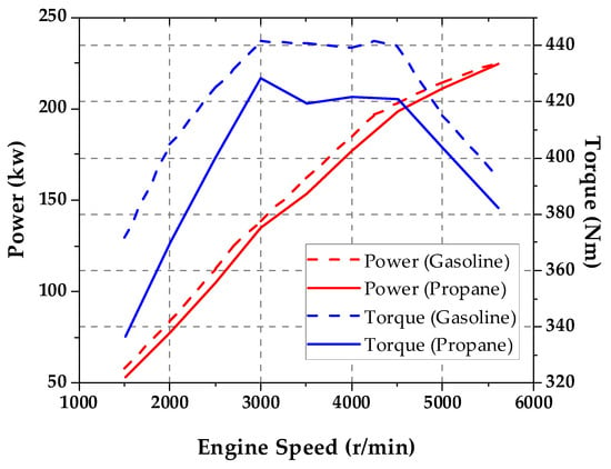
Figure 12.
Performance comparison between the gasoline base engine and the propane engine.
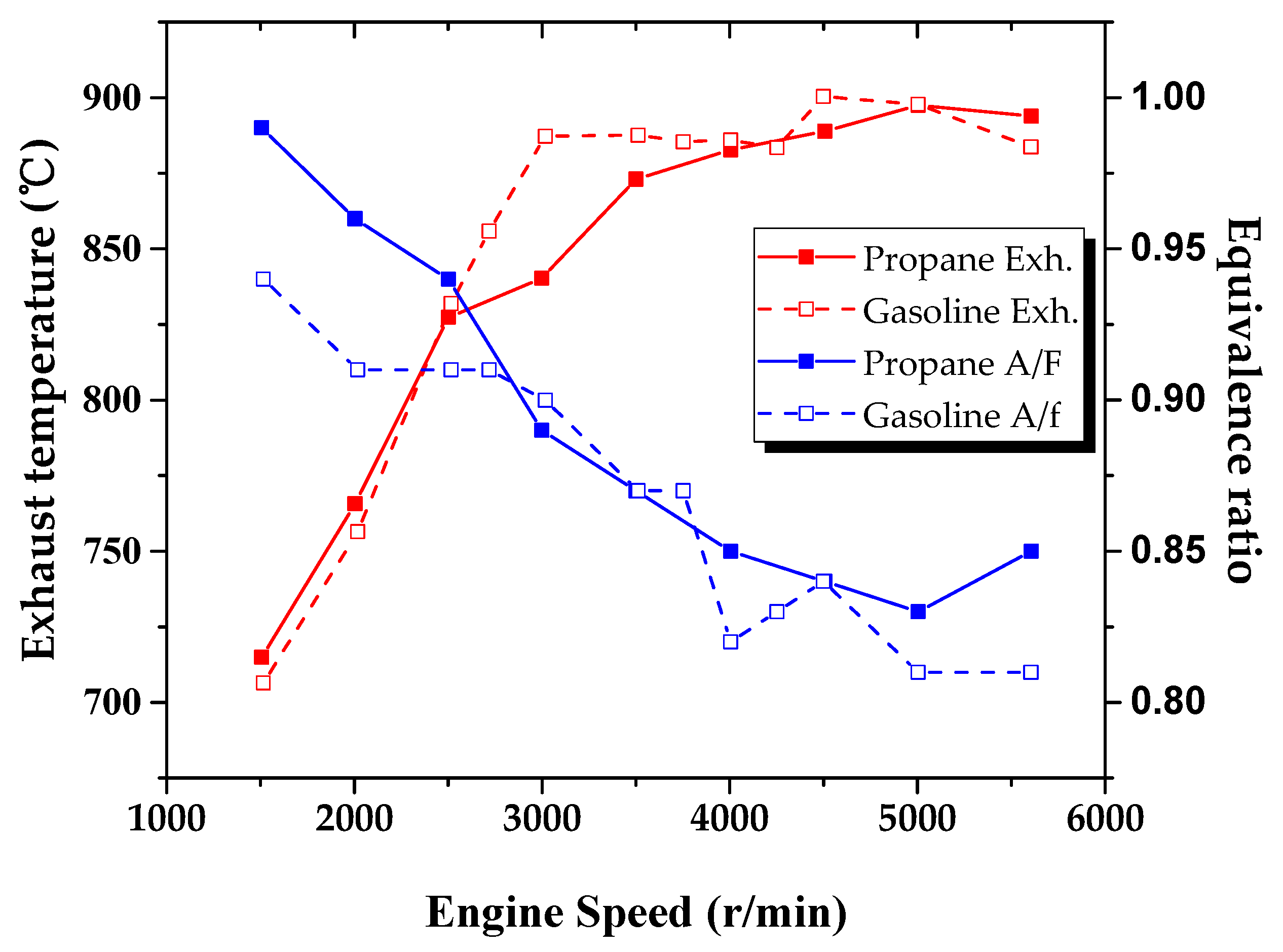
During combustion, nitrogen and oxygen in the intake air of an internal combustion engine react to generate NOx, which can either be the source of toxic substances such as nitroarenes, nitrosamines, and nitrate radicals or contribute to the formation of photochemical smog through reactions with ultraviolet radiation [23]. In addition, an excessively high exhaust gas temperature affects the durability of the engine parts and exhaust system; therefore, the exhaust temperature must be controlled at an appropriate level. In this study, the air–fuel ratio was controlled to maintain the exhaust gas temperature of both the gasoline and propane engines below 900 °C. Figure 13 shows the exhaust gas temperature results corresponding to the engine speed and air–fuel ratio under full-load driving conditions. The higher the engine speed, the richer the air–fuel ratio to maintain the proper exhaust gas temperature. Under the operating conditions of (5000 to 5500) rpm, the equivalence ratio of the gasoline engine was more tightly controlled than that of the propane engine. Better conditions are needed for exhaust gas temperature control as the BMEP of the gasoline engine is high, and more power is generated under high-rpm driving conditions.
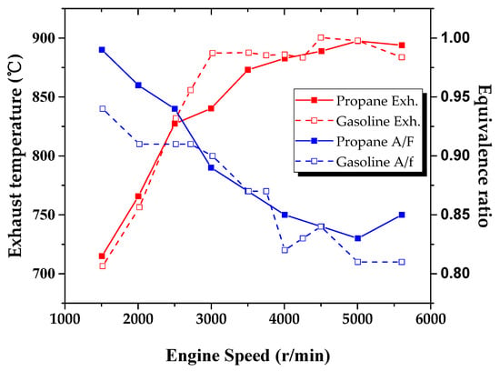
Figure 13.
Comparison of exhaust temperature and A/F between the gasoline engine and the propane engine under full-load conditions.
A slight difference was observed in the exhaust temperature results of the propane and gasoline engines at (2500 to 4000) rpm. Referring to the ignition timing results in Figure 8 and Figure 9, the ignition timing of the gasoline engine was more retarded than that of the propane engine at (2500 to 4000) rpm. If the ignition timing is retarded, ignition starts late, and the combustion process is lengthened on the expansion stroke [24]. Therefore, high-temperature exhaust gas is discharged through the exhaust pipe. Conversely, if the ignition timing is advanced, the combustion period during the expansion stroke is shortened, and the exhaust gas temperature is lowered owing to the cooling effect in the expansion stroke. Thus, a difference was observed in the exhaust gas temperature of the gasoline and propane engines under the same operating conditions.
3.2.3. Fuel Consumption Study
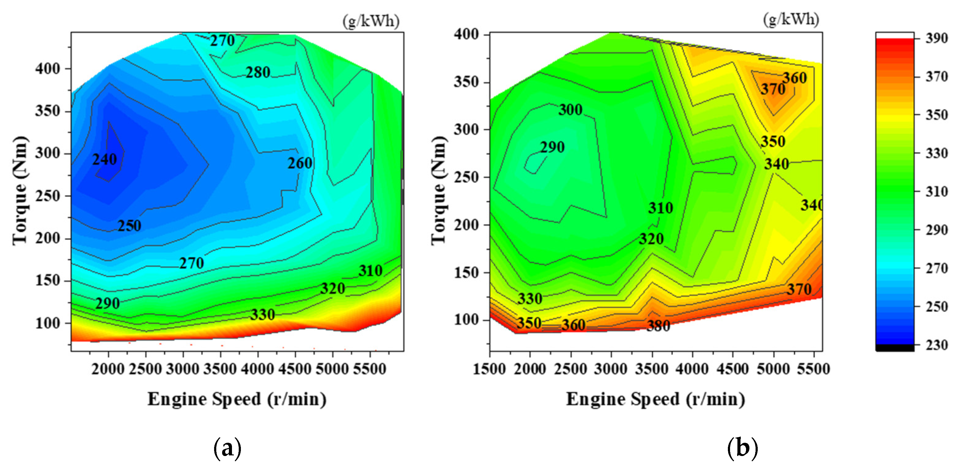
The fuel consumption of a maritime engine is an important measurement factor as it is closely related to the operating time of the ship. To measure the fuel consumption of the base engine, the BSFC results, which indicate the amount of fuel consumed per unit of power, corresponding to the rpm and load are shown in Figure 14a. The BSFC of the base engine was (240 to 330) g/kWh depending on the load. The highest efficiency was observed at 2000 rpm medium load, and the high-efficiency section was distributed in the 260 g/kWh region at up to 4000 rpm medium load. Figure 14b shows the BSFC results corresponding to the engine speed and load of the propane engine. The BSFC of the propane engine was distributed in the 300 g/kWh region under medium load operating at (1500 to 3000) rpm, and fuel consumption of 370 g/kWh was recorded at (4000 to 5500) rpm under full-load operating conditions. Compared with the gasoline engine, the propane engine exhibited higher overall BSFC results. Compared with the gasoline engine—which injects liquid when fuel is injected whereas the propane is injected in a gaseous form—the volume of the fuel in the mixture where fuel and air are mixed is larger for the propane engine. Therefore, the volumetric efficiency of the intake air of the propane engine is lower than that of the gasoline engine, thus resulting in increased fuel consumption [25,26].
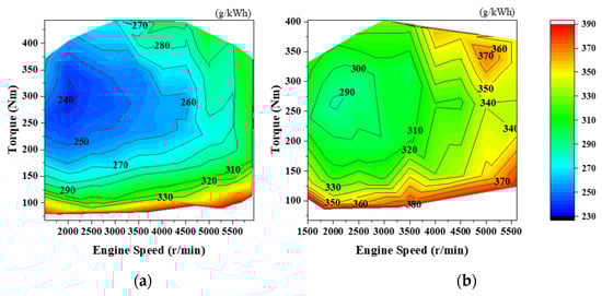
Figure 14.
BSFC maps of (a) the gasoline engine and (b) the propane engine under steady-state conditions.
By controlling the equivalence ratio at approximately 0.8 under the full-load condition at 4000 rpm or more to maintain the targeted exhaust temperature of the gasoline engine, the BSFC increased by approximately 30 g/kWh compared with that at 3500 rpm. On the other hand, in the case of the propane engine, by controlling the equivalence ratio at 0.85 under the full-load condition at 4000 rpm or more, the BSFC increased by approximately 50 g/kWh compared with that at 3500 rpm.
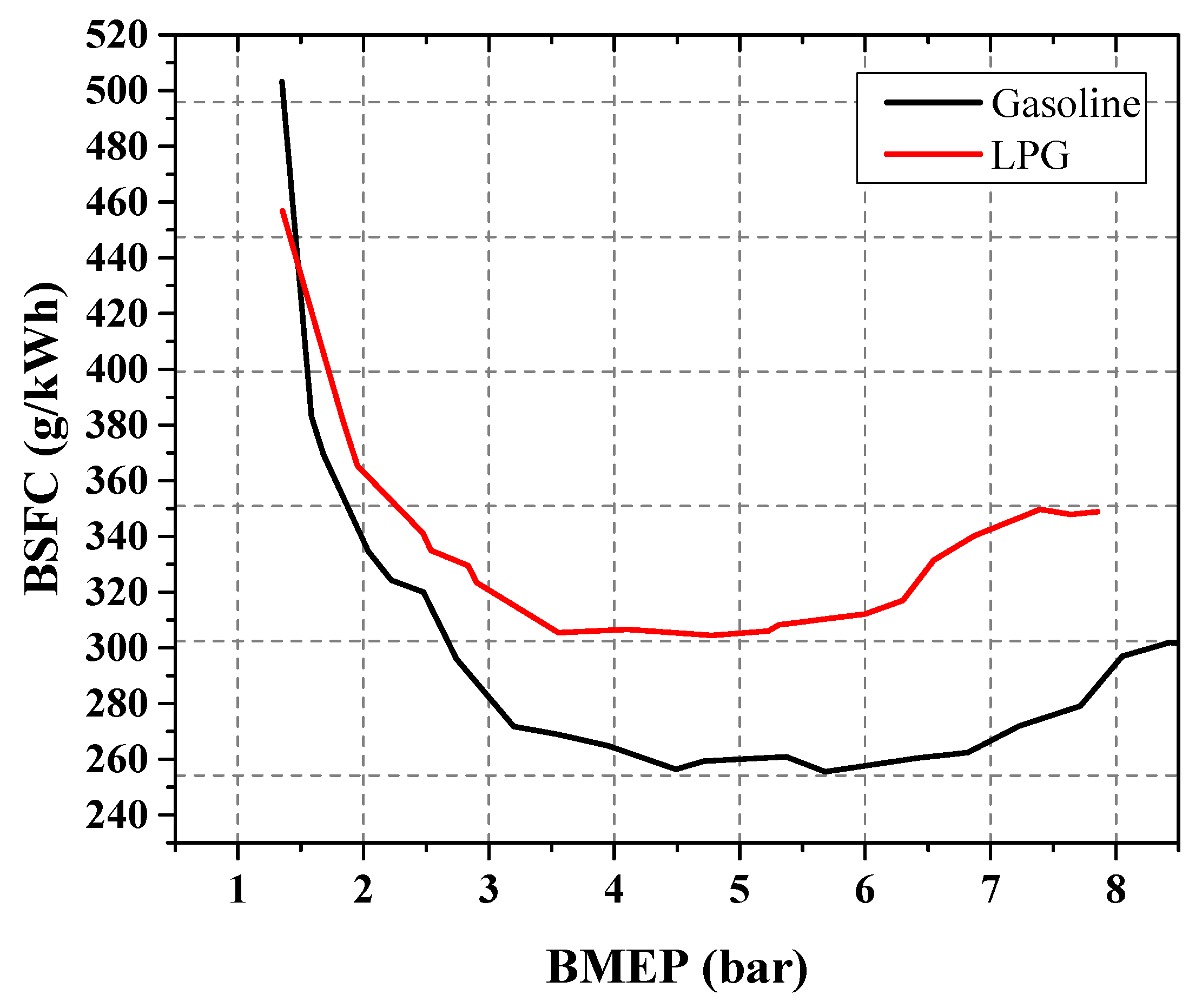
Figure 15 shows the comparison results of BSFC according to BMEP to quantitatively compare the fuel consumption of the gasoline and propane engines. Overall, the BSFC of the propane engine was higher than that of the gasoline engine. The heating value of propane (23.1 MJ/L) was approximately 27.8% lower than that of gasoline (32 MJ/L), and the fuel characteristics due to the low volumetric efficiency of propane caused power degradation. Therefore, compared with gasoline engines, propane engines consume more fuel to produce the same power [25,26].

Figure 15.
Comparison of BSFC according to BMEP of the gasoline and propane engines.
3.2.4. Cold-Start Performance
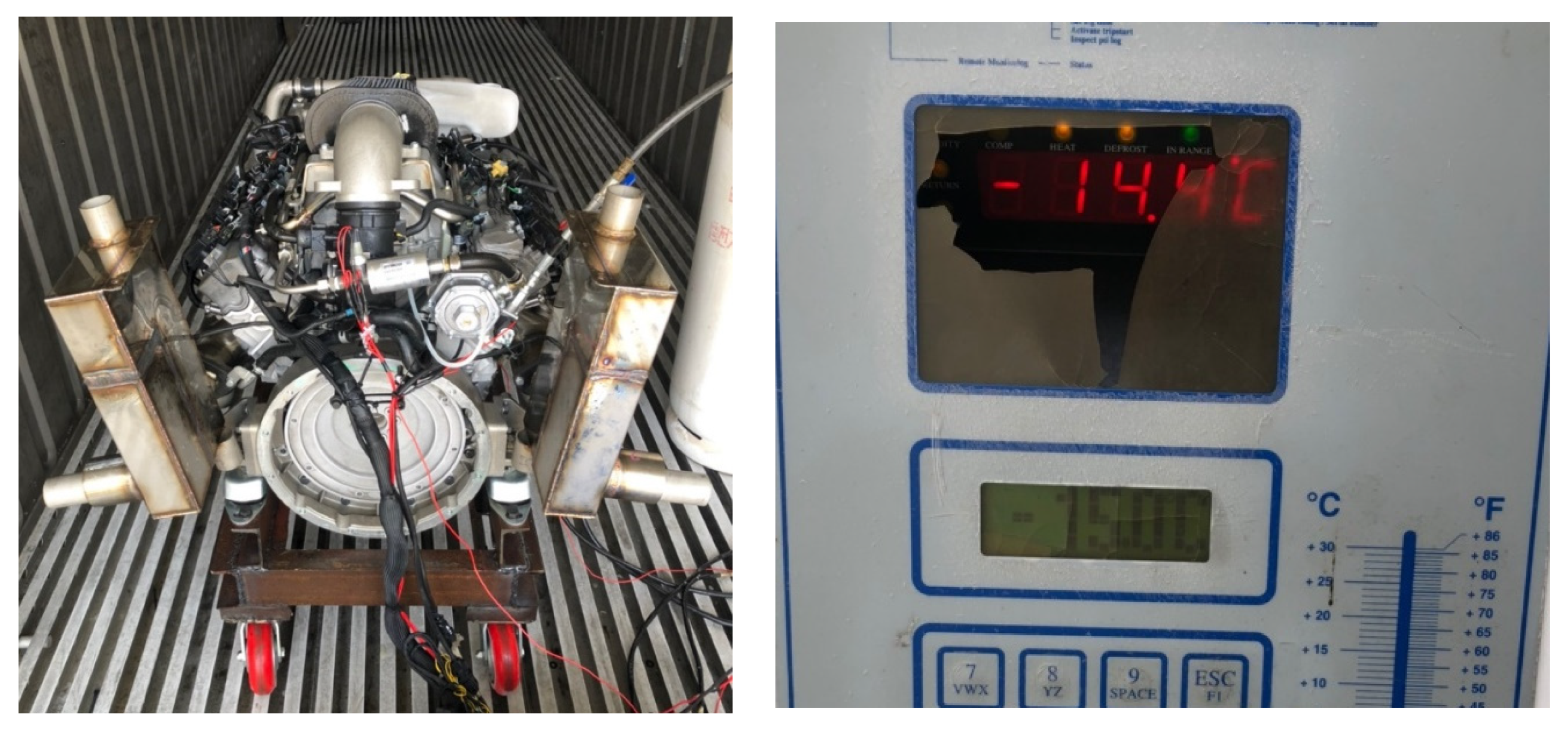
The propane engine developed in this study uses a system that vaporizes liquid propane with a vaporizer and uses gaseous fuel to drive the engine; therefore, vaporization heat management is important. When the engine is fully warmed, the 90 °C coolant heats the vaporizer, preventing icing and smoothly evaporating the fuel to maintain a stable fuel supply. However, when the engine is cooled in cold weather, the vaporization of liquid propane in the vaporizer becomes difficult. In this case, startability possibly deteriorates. Therefore, the starting performance was tested by simulating low-temperature conditions. Figure 16 shows the experimental device used for testing the starting performance under low-temperature conditions. The starting performance test was conducted after soaking the engine in a cold chamber at −15 °C for 12 h. Inside the cold chamber, the engine test was conducted without any additional load other than that of the flywheel. The viscosity of the engine oil was 5W30, and the antifreeze concentration of the coolant (ethylene glycol) was 50%. Figure 17 shows the engine speed and A/F measurement results during a cold start. To secure combustion stability and warm-up enrichment at the time of initial start-up, the equivalence ratio was set to be richer than the stoichiometry equivalence ratio. The engine was started after soaking for 12 h at −15 °C; the peak speed reached 1660 RPM after 1.2 s of cranking time. The engine speed was stabilized at idle speed for 0.7 s after reaching the peak speed, and the equivalence ratio was maintained at 0.74 during the starting process. Therefore, the starting performance test confirmed stable operation even at −15 °C. Given that the boiling point of propane is −42 °C, no problem was found with the fuel supply, and the low-temperature start was successful owing to the successful vaporization even at −15 °C. The cold-start performance test results confirmed the normal starting of the engine at −15 °C; thus, the engine can start under general marine operation conditions.

Figure 16.
Low-temperature chamber experimental equipment used for cold-start experiments.
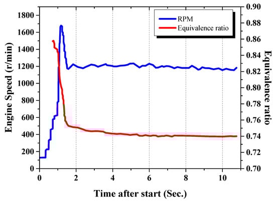
Figure 17.
Cold-start performance at −15 °C.
4. Conclusions
In this study, for the development of a gas-injection-type propane engine, a fuel supply system was fabricated, and research was conducted on optimal ignition timing and performance enhancement. As the fuel system was changed from gasoline to propane, a 1D simulation was conducted for the optimal control of the propane engine, along with experiments, and the following conclusions were drawn:
- In order to develop an environmentally friendly and economically viable propane engine, a 5.0 L gasoline base engine was converted to a propane engine. Research was conducted on the gas injection fuel system, ignition timing, and combustion optimization.
- Through 1D simulation modeling of the target propane engine and subsequent validation based on experimental results, it was determined that the error in engine torque was within 0.4%, BSFC within 1.17%, BMEP within 0.89, and ignition timing within 1.01%. Therefore, the reliability of the 1D simulation model was confirmed.
- As a result of the optimal ignition timing MBT investigation using 1D simulation, the development period was shortened, and an ignition timing map was configured for up to 44° BTDC with a 6° delay according to the operating conditions. Because propane has a higher octane number (112) than gasoline, the knocking resistance was exceptional, and the ignition timing was advanced compared to that of the gasoline-based engine. Therefore, it was possible to improve the thermal efficiency of the propane engine.
- The heating value of propane was approximately 27.8% lower than that of gasoline; hence, the BSFC result of the propane engine was higher than that of gasoline. However, due to gas injection, a well-formed mixture of intake air was achieved compared to liquid gasoline injection, allowing for faster combustion. Additionally, the higher octane number of propane (112) compared to gasoline (89) improved resistance to knocking, enabling advanced ignition timing and thereby increasing efficiency. For these reasons, the propane gas injection engine achieved a maximum power that was 95% of the gasoline-based engine and a maximum torque that was 97%.
- To test its cold-start performance, the propane engine was started after soaking in a cold chamber at −15 °C for 12 h. In the cold-start performance test, the engine speed reached 1660 RPM after 1.2 s from cranking, thereby confirming that the engine started well even under low-temperature conditions.
- This study involved the fabrication of a fuel system and the optimization of ignition timing for the development of a propane marine engine, as well as fundamental research on its performance. As part of our future work, research and development for a small-ship propane engine through IMO-regulated mode tests and onboard ship operation experiments will be conducted.
Author Contributions
Conceptualization, Y.K.; methodology, S.W.; software, S.P.; validation, J.W.J.; formal analysis, Y.K.; investigation, resources, data curation, B.Y.P.; writing—original draft preparation, Y.K.; writing—review and editing, K.L.; visualization, B.Y.P.; supervision, project administration, funding acquisition, K.L. All authors have read and agreed to the published version of the manuscript.
Funding
This research was supported by the Korea Institute of Marine Science & Technology Promotion (KIMST) funded by the Ministry of Oceans and Fisheries (grant number: 20220491).
Conflicts of Interest
The authors declare no conflict of interest.
References
- Fletcher, S.E.M.; Schaefer, H. Rising methane: A new climate challenge. Science 2019, 364, 932–933. [Google Scholar] [CrossRef]
- Anderson, T.R.; Hawkins, E.; Jones, P.D. CO2, the greenhouse effect and global warming: From the pioneering work of Arrhenius and Callendar to today’s Earth System Models. Endeavour 2016, 40, 178–187. [Google Scholar] [CrossRef] [PubMed]
- Ryu, J.; Lyu, Y.; Eom, M.; Jeon, M.; Kim, D.; Jung, S.; Kim, D. A Study on the Greenhouse Gas Control Strategies for Motor Vehicles. Natl. Inst. Environ. Res. 2005, 81–89. [Google Scholar]
- Oberthür, S.; Ott, H.E. The Kyoto Protocol: International Climate Policy for the 21st Century; Springer Science & Business Media: Berlin, Germany, 1999. [Google Scholar]
- Agreement, P. Paris Agreement; Report of the Conference of the Parties to the United Nations Framework Convention on Climate Change (21st Session, 2015: Paris); HeinOnline: Buffalo, NY, USA, 2015; p. 2017. [Google Scholar]
- IMO. Initial IMO Strategy on Reduction of GHG Emissions from Ships, Resolution MEPC. 304; Adopted on 13 April 2018; International Maritime Organization: London, UK, 2018. [Google Scholar]
- Joung, T.-H.; Kang, S.-G.; Lee, J.-K.; Ahn, J. The IMO initial strategy for reducing Greenhouse Gas (GHG) emissions, and its follow-up actions towards 2050. J. Int. Marit. Saf. Environ. Aff. Shipp. 2020, 4, 1–7. [Google Scholar] [CrossRef]
- Dieselnet IMO Marine Engine Regulations. Available online: https://dieselnet.com/standards/inter/imo.php (accessed on 7 October 2023).
- Emission Control Areas (ECAs) Designated under MARPOL Annex VI. Available online: https://www.imo.org/en/OurWork/Environment/Pages/Emission-Control-Areas-(ECAs)-designated-under-regulation-13-of-MARPOL-Annex-VI-(NOx-emission-control).aspx (accessed on 7 October 2023).
- Myśków, J.; Borkowski, T.; Bludszuweit, M.; Frohlingsdorf, W. Marine engine exhaust gas emission aftertreatment system concept. J. KONES 2011, 18, 307–315. [Google Scholar]
- Zhou, J.; Wang, H. Study on efficient removal of SOx and NOx from marine exhaust gas by wet scrubbing method using urea peroxide solution. Chem. Eng. J. 2020, 390, 124567. [Google Scholar] [CrossRef]
- Feng, S.; Xu, S.; Yuan, P.; Xing, Y.; Shen, B.; Li, Z.; Zhang, C.; Wang, X.; Wang, Z.; Ma, J.; et al. The Impact of Alternative Fuels on Ship Engine Emissions and Aftertreatment Systems: A Review. Catalysts 2022, 12, 138. [Google Scholar] [CrossRef]
- Zorzoană, I.-A. The Activity of Transposing Directive 2014/94/EU of the European Parliament and Council of 22 October 2014 on the Deployment of Alternative Fuels Infrastructure. the Post-Transposing Attributions of the Romanian Energy Regulatory Authority. Chall. Knowl. Soc. 2019, 855–861. [Google Scholar]
- Li, J.; Wu, B.; Mao, G. Research on the performance and emission characteristics of the LNG-diesel marine engine. J. Nat. Gas Sci. Eng. 2015, 27, 945–954. [Google Scholar] [CrossRef]
- Park, T.; So, S.; Jeong, B.; Zhou, P.; Lee, J.-U. Life cycle assessment for enhanced Re-liquefaction systems applied to LNG carriers; effectiveness of partial Re-liquefaction system. J. Clean. Prod. 2021, 285, 124832. [Google Scholar] [CrossRef]
- Yeo, S.-J.; Kim, J.; Lee, W.-J. Potential economic and environmental advantages of liquid petroleum gas as a marine fuel through analysis of registered ships in South Korea. J. Clean. Prod. 2022, 330, 129955. [Google Scholar] [CrossRef]
- Mahmud, S.; Ahmed, S.A. Prospect of LPG for Marine Engines in Bangladesh. Syed Aurongzeb, Prospect of LPG for Marine Engines in Bangladesh. In Proceedings of the International Conference on Marine Technology, BUET, Dhaka, Bangladesh, 21–22 December 2022. [Google Scholar]
- Wang, Y.; Cao, Q.; Liu, L.; Wu, Y.; Liu, H.; Gu, Z.; Zhu, C. A review of low and zero carbon fuel technologies: Achieving ship carbon reduction targets. Sustain. Energy Technol. Assess. 2022, 54, 102762. [Google Scholar] [CrossRef]
- IMO. Guidelines on Alternative Design and Arrangements for Fire Safety; International Maritime Organisation: London, UK, 2001. [Google Scholar]
- Erkuş, B.; Karamangil, M.İ.; Sürmen, A. Enhancing the heavy load performance of a gasoline engine converted for LPG use by modifying the ignition timings. Appl. Therm. Eng. 2015, 85, 188–194. [Google Scholar] [CrossRef]
- Okamoto, K.; Ichikawa, T.; Saitoh, K.; Oyama, K.; Hiraya, K.; Urushihara, T. Study of Antiknock Performance Under Various Octane Numbers and Compression Ratios in a DISI Engine. SAE Trans. 2003, 112, 1079–1087. [Google Scholar]
- Garin, F. Mechanism of NOx decomposition. Appl. Catal. A Gen. 2001, 222, 183–219. [Google Scholar] [CrossRef]
- Masi, M.; Gobbato, P. Measure of the volumetric efficiency and evaporator device performance for a liquefied petroleum gas spark ignition engine. Energy Convers. Manag. 2012, 60, 18–27. [Google Scholar] [CrossRef]
- Choi, G.; Cho, U. A Study on Reduction of Exhaust Gas Temperature in Retrofitted LPG Fueled Engine Based Mdium-Duty Diesel Engine. Trans. Korean Soc. Automot. Eng. 2003, 11, 63–68. [Google Scholar]
- Irimescu, A. Study of volumetric efficiency for spark ignition engines using alternative fuels. Analele Univ. Eftimie Murgu 2010, 2, 149–154. [Google Scholar]
- Gumus, M. Effects of volumetric efficiency on the performance and emissions characteristics of a dual fueled (gasoline and LPG) spark ignition engine. Fuel Process. Technol. 2011, 92, 1862–1867. [Google Scholar] [CrossRef]


Disclaimer/Publisher’s Note: The statements, opinions and data contained in all publications are solely those of the individual author(s) and contributor(s) and not of MDPI and/or the editor(s). MDPI and/or the editor(s) disclaim responsibility for any injury to people or property resulting from any ideas, methods, instructions or products referred to in the content. |
© 2023 by the authors. Licensee MDPI, Basel, Switzerland. This article is an open access article distributed under the terms and conditions of the Creative Commons Attribution (CC BY) license (https://creativecommons.org/licenses/by/4.0/).