A Decentralized Control Strategy for Series-Connected Single-Phase Two-Stage Photovoltaic Grid-Connected Inverters
Abstract
:1. Introduction
2. Equivalent Model of Series-Connected PV Inverters Grid-Connected System
3. Design of the Decentralized Control Strategy for Series-Connected PV Inverters
4. Steady-State Analysis
5. Stability Analysis
5.1. Small Signal Modeling
5.2. System Stabilization Conditions
6. Simulation Verification
6.1. Simulation Settings
6.2. Simulation Results
- (1)
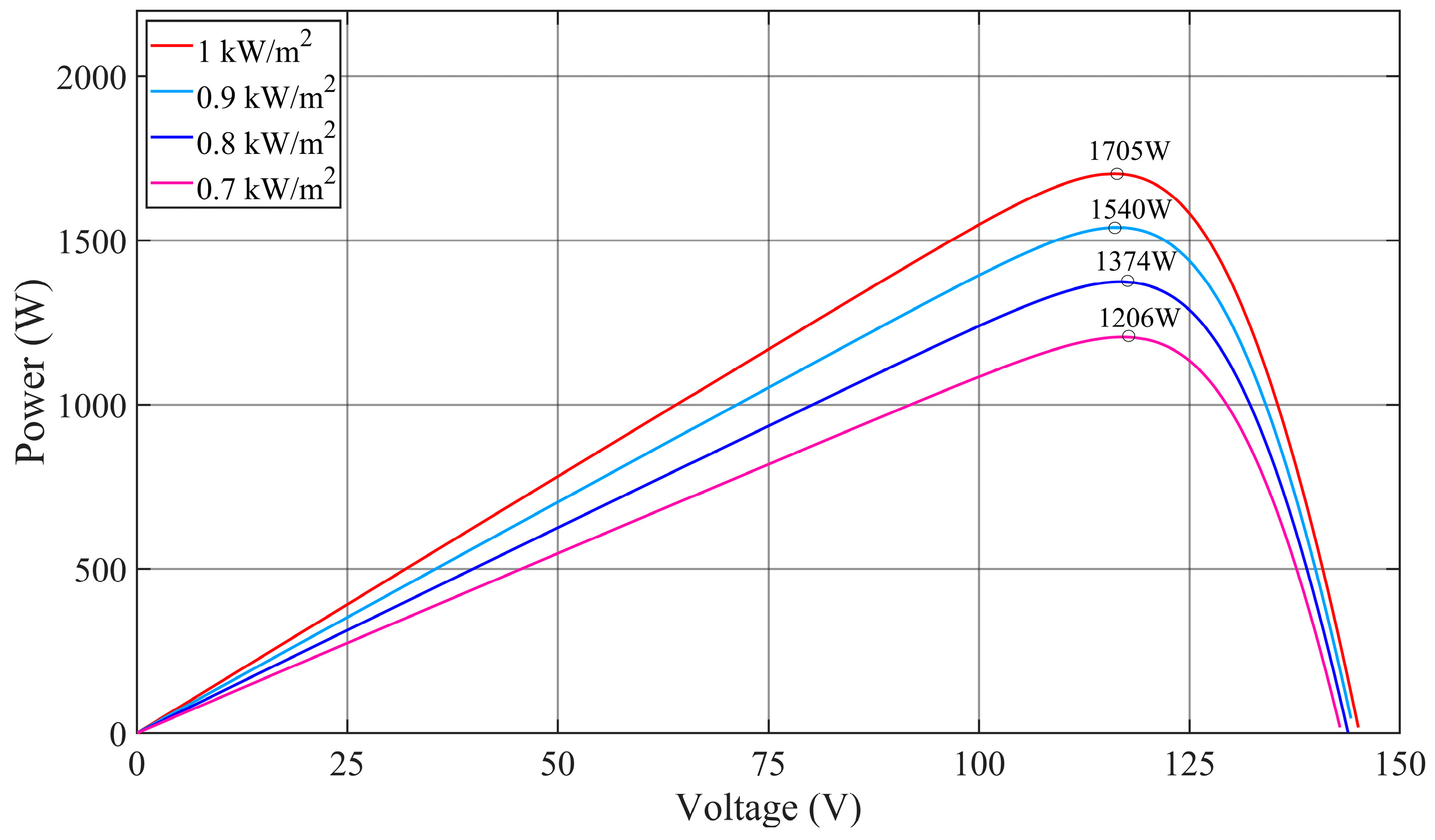
- Output active power. It can be seen from Figure 4 that, in the first stage, the light intensity of the three units is the same (1000 W/m2), therefore, the output active power of each unit is the same, given as = = = 1681 W. In the second stage, when t = 3 s, and immediately decrease, and finally reach a new steady state, there, = 1356W, = 1186 W, and the steady-state value of is not affected by unit 2 and unit 3 and does not change; = 1681 W still. In the third stage, when t = 6 s, immediately drops and eventually reaches a new steady state, with = 1534 W. The steady-state values of and are not affected by unit 1 and are the same as the steady-state values in the second stage, which are = 1356 W and = 1186 W. It can be seen from Figure 3 that the maximum output power of the PV modules at 1000 W/m2, 900 W/m2, 800 W/m2, and 700 W/m2 is 1705 W, 1540 W, 1374 W, and 1206 W, respectively. Considering the power loss in the inverters and lines, it can be considered that the active power output of these units realize the real-time tracking of the maximum power of PV arrays, and each unit does not affect each other.

- (2)
- Output reactive power. It can be seen from Figure 5 that in the first stage, the reactive power output of each unit is the same, with = −620 Var, which realizes the reactive power sharing between these units. In the second stage, at steady state, = −2283 Var, = −1888 Var, and = −1677 Var. In the third stage, at steady state, = −2382 Var, = −2152 Var, and = −1911 Var. The above results agree with Equation (11).

- (3)
- Frequency. As can be seen from Figure 6, the output frequencies of all series units converge to the grid frequency (50 Hz) in steady state with a deviation range of no more than 0.05 Hz. The output voltage frequency is self-synchronized with the grid frequency.

- (4)
- DC side voltage of the inverter. It can be seen from Figure 7 that despite the change in light intensity, the DC side voltage of all series inverters can converge to the reference value (200 V) quickly, and the voltage ripple does not exceed 2 V, which verifies the effectiveness of Equation (5) for the DC side voltage regulation of the inverter.

- (5)
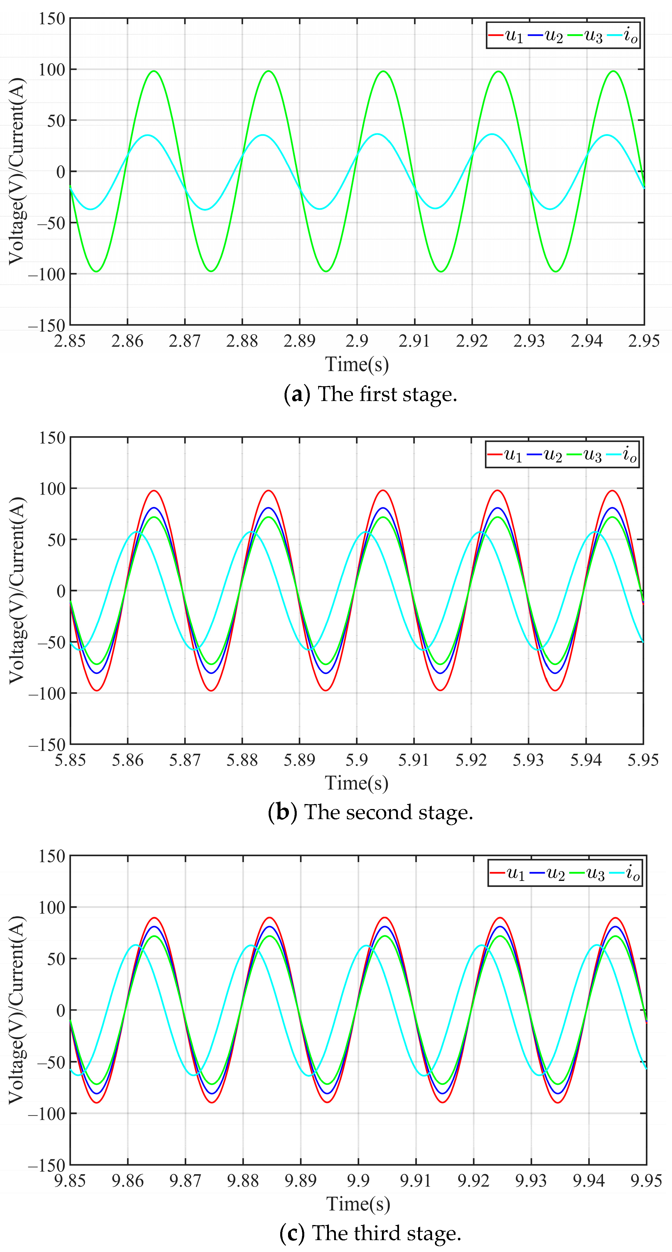
- Output voltage and current. The common output current and inverter output voltages at different stages are shown in Figure 8. It can be seen from Figure 8a that in the first stage, because the light intensity is the same, the amplitude (V1 = V2 = V3 = 95.8 V) and phase of the output voltages u1, u2, and u3 are the same. In the second stage, only the light intensity of units 2 and 3 change. It can be seen from Figure 8b that the phase of u1, u2, and u3 is still the same, the amplitude V1 remains unchanged, but V2 and V3 have changed, which are given by V1 = 95.8 V, V2 = 77.3 V, and V3 = 67.6 V. In the third stage, only the light intensity of unit 1 changes. It can be seen from Figure 8c that the phases of u1, u2, and u3 are still the same, and the output voltage amplitudes are V1 = 87.5 V, V2 = 77.3 V, and V3 = 67.6 V. The result data above satisfy Equations (6) and (10), which are consistent with the analytical conclusions of Section 3. As the output voltage amplitude of each unit decreases, the power factor of the system also decreases, which is reflected in Figure 8 as the phase difference between the output current io and voltage u1 (or u2, u3) becomes larger.

- (6)
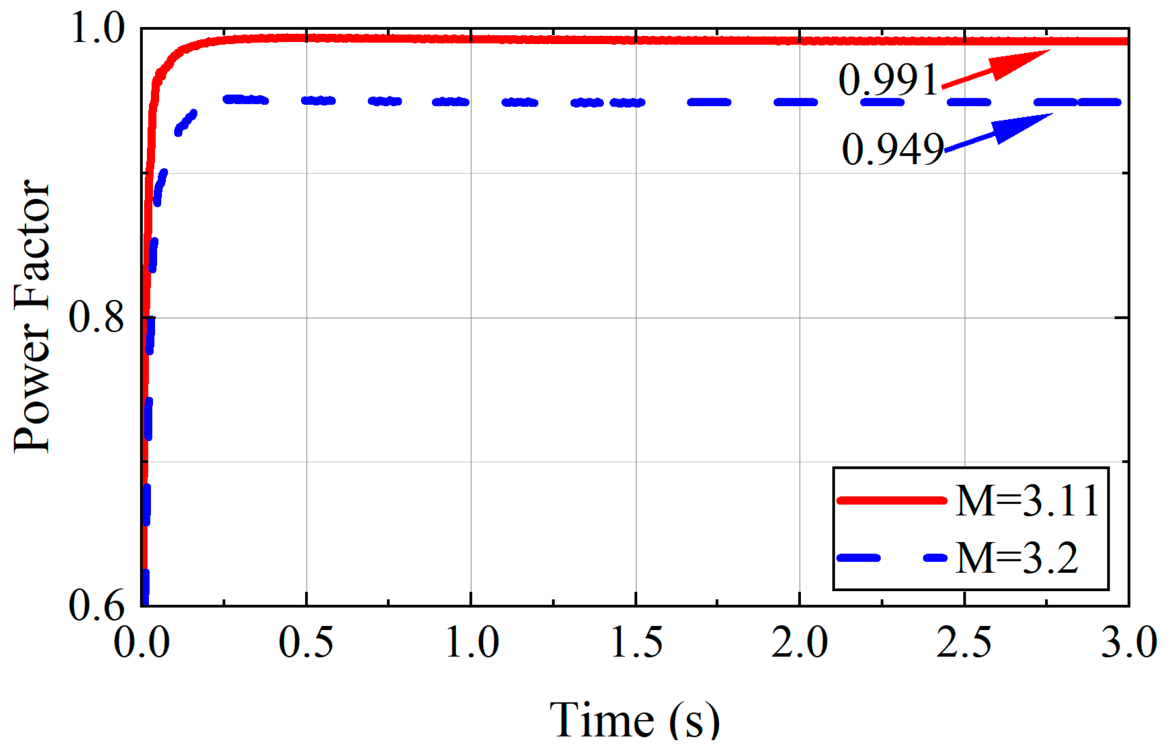
- Power factor. To verify the relationship between the power factor of the system and the M value, a comparative test is carried out in the first stage of simulation. It can be seen from Figure 9 that when M decreases from 3.2 to 3.11, the power factor increases from 0.949 to 0.991. It shows that the value of M affects the size of the power factor, and the relationship is inversely proportional, which is consistent with the analysis conclusion in Section 5 of this paper.

7. Conclusions
Author Contributions
Funding
Data Availability Statement
Conflicts of Interest
References
- Kavya Santhoshi, B.; Mohana Sundaram, K.; Padmanaban, S.; Holm-Nielsen, J.B.; Prabhakaran, K.K. Critical Review of PV Grid-Tied Inverters. Energies 2019, 12, 1921. [Google Scholar] [CrossRef]
- Tayab, U.B.; Roslan, M.A.B.; Hwai, L.J.; Kashif, M. A review of droop control techniques for microgrid. Renew. Sustain. Energy Rev. 2017, 76, 717–727. [Google Scholar] [CrossRef]
- Wu, F.; Sun, B.; Duan, J.; Zhao, K. Online Variable Topology-type Photovoltaic Straight Connected Inverter. IEEE Trans. Ind. Electron. 2015, 62, 4814–4822. [Google Scholar] [CrossRef]
- Moeini, N.; Bahrami-Fard, M.; Shahabadini, M.; Azimi, S.M.; Iman-Eini, H. Passivity-Based Control of Single-Phase Cascaded H-Bridge Grid-Connected Photovoltaic Inverter. IEEE Trans. Ind. Electron. 2023, 70, 1512–1520. [Google Scholar] [CrossRef]
- Vanti, S.; Bana, P.R.; D’Arco, S.; Amin, M. Single-Stage Grid-Connected PV System With Finite Control Set Model Predictive Control and an Improved Maximum Power Point Tracking. IEEE Trans. Sustain. Energy 2022, 13, 791–802. [Google Scholar] [CrossRef]
- Guisso, R.A.; Andrade, A.M.S.S.; Hey, H.L.; Martins, M.L.d.S. Grid-tied single source quasi-Z-source cascaded multilevel inverter for PV applications. Electron. Lett. 2019, 55, 342–343. [Google Scholar] [CrossRef]
- Tafti, H.D.; Maswood, A.I.; Konstantinou, G.; Townsend, C.D.; Acuna, P.; Pou, J. Flexible Control of Photovoltaic Grid-Connected Cascaded H-Bridge Converters During Unbalanced Voltage Sags. IEEE Trans. Ind. Electron. 2018, 65, 6229–6238. [Google Scholar] [CrossRef]
- Mhiesan, H.; Wei, Y.; Siwakoti, Y.P.; Mantooth, H.A. A Fault-Tolerant Hybrid Cascaded H-Bridge Multilevel Inverter. IEEE Trans. Power Electron. 2020, 35, 12702–12715. [Google Scholar] [CrossRef]
- Sarkar, I.; Fernandes, B.G. A Hybrid Symmetric Cascaded H-Bridge Multilevel Converter Topology. IEEE J. Emerg. Sel. Top. Power Electron. 2023, 11, 4032–4044. [Google Scholar] [CrossRef]
- Calais, M.; Agelidis, V.G.; Dymond, M.S. A cascaded inverter for transformerless single-phase grid-connected photovoltaic systems. Renew. Energy 2001, 22, 255–262. [Google Scholar] [CrossRef]
- Liu, P.; Chao, Z.; Duan, S. A Digital Interconnected Bus Providing Voltage Synchronization for the Modular Series-Connected Inverters. IEEE Trans. Power Electron. 2020, 35, 12590–12594. [Google Scholar] [CrossRef]
- Liu, P.; Song, L.; Duan, S. A Synchronization Method for the Modular Series-Connected Inverters. IEEE Trans. Power Electron. 2020, 35, 6686–6690. [Google Scholar] [CrossRef]
- Lu, F.; Choi, B.; Maksimovic, D. Autonomous control of series-connected low voltage photovoltaic microinverters. In Proceedings of the 2015 IEEE 16th Workshop on Control and Modeling for Power Electronics (COMPEL), Vancouver, BC, Canada, 12–15 July 2015; pp. 1–6. [Google Scholar]
- Xu, B.; Tu, H.; Du, Y.; Yu, H.; Liang, H.; Lukic, S. A Distributed Control Architecture for Cascaded H-Bridge Converter With Integrated Battery Energy Storage. IEEE Trans. Ind. Appl. 2021, 57, 845–856. [Google Scholar]
- He, J.; Li, Y.; Wang, C.; Pan, Y.; Zhang, C.; Xing, X. Hybrid Microgrid With Parallel- and Series-Connected Microconverters. IEEE Trans. Power Electron. 2018, 33, 4817–4831. [Google Scholar] [CrossRef]
- Zhang, L.; Sun, K.; Li, Y.W.; Lu, X.; Zhao, J. A Distributed Power Control of Series-Connected Module-Integrated Inverters for PV Grid-Tied Applications. IEEE Trans. Power Electron. 2018, 33, 7698–7707. [Google Scholar] [CrossRef]
- Jafarian, H.; Bhowmik, S.; Parkhideh, B. Hybrid Current-/Voltage-Mode Control Scheme for Distributed AC-Stacked PV Inverter With Low-Bandwidth Communication Requirements. IEEE Trans. Ind. Electron. 2018, 65, 321–330. [Google Scholar] [CrossRef]
- Hou, X.; Sun, Y.; Han, H.; Liu, Z.; Yuan, W.; Su, M. A fully decentralized control of grid-connected cascaded inverters. IEEE Trans. Sustain. Energy 2019, 10, 315–317. [Google Scholar] [CrossRef]
- Sun, Y.; Li, L.; Shi, G.; Hou, X.; Su, M. Power Factor Angle Droop Control—A General Decentralized Control of Cascaded Inverters. IEEE Trans. Power Deliv. 2021, 36, 465–468. [Google Scholar] [CrossRef]
- Hou, X.; Sun, Y.; Hua, H.; Zhang, J.; Su, M.; Wang, B.; Zhang, X. A General Decentralized Control Scheme for Medium-/High-Voltage Cascaded STATCOM. IEEE Trans. Power Syst. 2018, 33, 7296–7300. [Google Scholar] [CrossRef]
- Li, L.; Sun, Y.; Hua, H.; Shi, G.; Su, M.; Zheng, M. A Decentralized Control for Cascaded Inverters in Grid-Connected Applications. IEEE Trans. Ind. Electron. 2020, 67, 8064–8071. [Google Scholar] [CrossRef]
- Luo, C.; Su, M.; Yuan, W.; Sun, Y.; Han, H.; Wang, H. A decentralized control for cascaded PV inverter system in grid-connected mode. In Proceedings of the 2017 Chinese Automation Congress (CAC), Jinan, China, 20–22 October 2017; pp. 6851–6856. [Google Scholar]
- Luo, Z.; Qin, J.; Zhou, F.; Wen, Y. A Decentralized Control Strategy for Single-phase Cascaded Photovoltaic Inverters with MPPT Ability. IET Renew. Power Gener. 2023, 17, 2679–2686. [Google Scholar]


| Symbol | Value | Symbol | Value |
|---|---|---|---|
| 311 V | 200 V | ||
| 50 Hz | 0.1 + j2 Ω | ||
| 97.2 V | M | 3.2 | |
| 100π rad/s | N | 3 | |
| m | 5 × 10⁻³ | 2 | |
| 10 kHz | 4 |
| Symbol | Value | Symbol | Value |
|---|---|---|---|
| 213.15 W | 29 V | ||
| 36.3 V | 7.35 A | ||
| 7.84 A |
Disclaimer/Publisher’s Note: The statements, opinions and data contained in all publications are solely those of the individual author(s) and contributor(s) and not of MDPI and/or the editor(s). MDPI and/or the editor(s) disclaim responsibility for any injury to people or property resulting from any ideas, methods, instructions or products referred to in the content. |
© 2023 by the authors. Licensee MDPI, Basel, Switzerland. This article is an open access article distributed under the terms and conditions of the Creative Commons Attribution (CC BY) license (https://creativecommons.org/licenses/by/4.0/).
Share and Cite
Luo, Z.; Zhang, B.; Li, L.; Tang, L. A Decentralized Control Strategy for Series-Connected Single-Phase Two-Stage Photovoltaic Grid-Connected Inverters. Energies 2023, 16, 7099. https://doi.org/10.3390/en16207099
Luo Z, Zhang B, Li L, Tang L. A Decentralized Control Strategy for Series-Connected Single-Phase Two-Stage Photovoltaic Grid-Connected Inverters. Energies. 2023; 16(20):7099. https://doi.org/10.3390/en16207099
Chicago/Turabian StyleLuo, Zhaoxu, Bo Zhang, Lang Li, and Lixing Tang. 2023. "A Decentralized Control Strategy for Series-Connected Single-Phase Two-Stage Photovoltaic Grid-Connected Inverters" Energies 16, no. 20: 7099. https://doi.org/10.3390/en16207099
APA StyleLuo, Z., Zhang, B., Li, L., & Tang, L. (2023). A Decentralized Control Strategy for Series-Connected Single-Phase Two-Stage Photovoltaic Grid-Connected Inverters. Energies, 16(20), 7099. https://doi.org/10.3390/en16207099


