Article

La0.6Sr0.4MnO3-Based Fuel Electrode Materials for Solid Oxide Electrolysis Cells Operating under Steam, CO2, and Co-Electrolysis Conditions

by
Vaibhav Vibhu
1,*,
Izaak C. Vinke
1,
Rüdiger-A. Eichel
1,2 and
L. G. J. (Bert) de Haart
1
1
Institute of Energy and Climate Research, Fundamental Electrochemistry (IEK-9), Forschungszentrum Jülich GmbH, 52425 Jülich, Germany
2
Institute of Physical Chemistry, RWTH Aachen University, 52074 Aachen, Germany
*
Author to whom correspondence should be addressed.
Energies 2023, 16(20), 7115; https://doi.org/10.3390/en16207115
Submission received: 29 August 2023 / Revised: 9 October 2023 / Accepted: 13 October 2023 / Published: 17 October 2023
(This article belongs to the Section B: Energy and Environment)

Abstract

:
The conventional Ni–YSZ (yttria-stabilized zirconia) fuel electrode experiences severe degradation due to Ni- agglomeration and migration away from the electrolyte. Therefore, herein, we have considered Ni free electrodes, i.e., La0.6Sr0.4MnO3-δ (LSM)-based perovskite oxides as fuel electrodes. The LSM perovskite phase transforms into a Ruddlesden–Popper LSM (RP-LSM) phase with exsolved MnOx under reducing atmospheres. The RP-LSM is mainly interesting due to its good electrical conductivity, redox stability, and acceptable electrochemical behaviour. In this work, we synthesized the LSM powder and characterized it using several methods including X-ray diffraction (XRD), thermogravimetry analyses (TGA), four-probe conductivity, and scanning electron microscope with energy-dispersive X-ray spectroscopy (SEM-EDX). Finally, the electrolyte-supported single cells were fabricated and electrochemically characterized using AC and DC techniques under electrolysis conditions. In addition to pure LSM fuel electrodes, we have also investigated the electrochemical behaviour of LSM + YSZ (50:50) and LSM + GDC (50:50) composite fuel electrodes. The single cells containing LSM and LSM + GDC fuel electrodes show higher cell performance than LSM + YSZ. For instance, current densities of 1, 1.03, and 0.51 A·cm−2 at 1.5 V are obtained for LSM, LSM + GDC, and LSM + YSZ fuel electrodes containing single cells, respectively, with a 50% N2 and 50% H2O feed gas mixture. Moreover, the performance of the cell was also investigated under co-electrolysis with 50% CO2 and 50% H2O and under direct CO2 electrolysis conditions with 100% CO2 fuel gas.

1. Introduction

The high-temperature electrolysis using solid oxide electrolysis cells (SOECs) has gained considerable attention as it consumes less electrical energy for fuel dissociation in comparison to low-temperature electrolysis [1,2,3,4]. The high operating temperatures (700–900 °C) of SOECs typically offer fast reaction kinetics and consequently high energy conversion efficiency. Furthermore, these SOECs can be used not only for the electrolysis of steam, but also for CO2 and co-electrolysis [5,6,7,8]. Despite numerous advantages of high-temperature SOEC over low-temperature electrolysis, its performance and stability during long-term processes are the major issues that still need to be solved for widespread application. The performance and long-term stability of SOEC clearly depend on the operational conditions such as current load, temperature, and fuel gas composition, as well as on the stability of both oxygen and fuel electrode materials [9,10]. However, since the fuel electrode comes into contact with different types of fuel, its stability under different fuel gas atmospheres is important.
So far, the state-of-the-art Ni–YSZ (yttria-stabilized zirconia) fuel electrodes have been extensively studied for high-temperature SOECs [4,10,11,12,13,14,15,16,17]. In general, Ni-based materials are considered good fuel electrodes due to their high electronic conductivity, good catalytic activity, and thermal expansion coefficient, which is comparable to that of the electrolyte [13,14].
However, Ni-YSZ fuel electrodes containing single cells or stacks show poor stability in long-term operations under SOEC conditions [18,19,20,21,22,23,24], mainly due to nickel depletion near the electrode/electrolyte interface, agglomeration of nickel particles, electrode active layer densification, poor redox stability, deactivation of Ni by coking, and sulphur poisoning [16,25]. Recently, the fuel electrode based on Ni-gadolinium doped ceria oxide (GDC) has attracted a lot of attention as an alternative to the conventional Ni-YSZ electrode [26,27,28]. This Ni-GDC based cermet electrode is especially attractive due to the mixed ionic and electronic conductivity of GDC, which improves the kinetics of charge transfer at the interface and thus enhances the performance of SOECs [26,29,30,31]. The Ni-GDC electrode solved some of the problems observed with the Ni-YSZ electrode with improved performance but could not prevent Ni depletion and agglomeration [25,30,32,33]. Therefore, the search for new electrode materials is crucial in order to enhance the overall performance and durability of SOECs. In this respect, several perovskite-based fuel electrode materials have been proposed and investigated, for ex. La0.75Sr0.25Cr0.5Mn0.5O3-δ (LSCM), La(Sr)Fe(Mn)O3−δ (LSFM), Sr2Fe1.5Mo0.5O6-δ (SFM), SrMn0.5Nb0.5O3-δ, PrBaMn2O5+δ, and doped SrTiO3 [34,35,36,37,38,39,40]. These perovskite-based materials have been identified as promising fuel electrode materials due to their redox stability in a wide range of pO2 and good physico-chemical and electrochemical properties. Moreover, Mn- and Fe-based perovskites have shown promising behaviour as SOEC cathodes; for example, La0.6Sr0.4Fe0.8Mn0.2O3 (LSFM) shows good activity and selectivity for CO2 electrolysis, and a current density of 0.52 A·cm−2 at 1.6 V and 900 °C is achieved under CO2 electrolysis conditions [40]. In addition, La0.75Sr0.25Cr0.5Mn0.5O3 (LSCM) shows a current density of 0.43 and 0.59 A·cm−2 at 1.6 V and 850 °C with 20 and 80 vol.% AH, respectively, indicating that these Mn-based perovskites are promising candidates for fuel electrodes [41]. However, the performance of pure LSM as a fuel electrode has not yet been investigated under electrolysis conditions.
Therefore, in this work, we have considered lanthanum strontium magnetite, i.e., La0.6Sr0.4MnO3 (LSM), and attempted to investigate its behaviour as a fuel electrode material for SOECs. LSM is a purely electronic conductor and is well known for being used for oxygen electrodes for solid oxide cells [42,43,44]. However, under a reducing atmosphere, it transforms into a Ruddlesden–Popper (La0.6Sr0.4)2MnO4±δ phase and MnOx [45]. First, the La0.6Sr0.4MnO3 (LSM) powder was synthesized, and its behaviour and stability under a reducing atmosphere were investigated via XRD, TGA, four-probe DC conductivity, and SEM. Then, electrolyte-supported single cells (ESCs) were prepared and characterized using DC and AC techniques at 900 °C under steam electrolysis, co-electrolysis, and CO2-electrolysis conditions. Furthermore, composite electrodes with YSZ and GDC, i.e., LSM+GDC (50:50 by weight) and LSM + YSZ (50:50 by weight), were also prepared and investigated as a fuel electrode under electrolysis conditions.

2. Experimental Procedure

2.1. Powder Preparation

La0.6Sr0.4MnO3 (LSM) powder was prepared via solid-state synthesis method. The corresponding precursors were La2O3 (Aldrich chem, 99.9%), SrCO3 (Sigma Aldrich, 99%), and MnO2 (Alfa Aesar, 99%). First, La2O3 was pre-fired at 900 °C overnight to remove the water content, due to its highly hygroscopic character. The precursors were weighed according to their composition, then ball-milled for 4 h at 250 rpm using zirconia balls and isopropanol. After drying at 80 °C overnight, the final annealing was performed at 1100 °C for 8 h in air, leading to well-crystallized phases. The obtained powders were crushed and milled again with zirconia balls and isopropanol for 8 h with the aim of obtaining a mean particle size of about 1 µm.

2.2. Powder Characterization

After synthesis, the powders were characterized via X-Ray diffraction (XRD) at room temperature using a PANanalytical X’pert MPD diffractometer with Cu-Kα incident radiation (λ = 1.5418 Å). The morphologies of the powder, as well as the microstructure of the electrode, were analysed using a scanning electron microscope (Quqnta FEG 650, FEI equipped with an EDS detector) operating at 20 kV. The particle size of the powder was determined by measuring the average of the size of several individual particles using SEM.
The TGA experiments were carried out using a TA Instrument® TGA-5500 device in order to determine the weight loss as a function of temperature under oxidising and reducing atmospheres. For that, first, two heating and cooling cycles were performed in the air up to 1000 °C with a rate of 2 °C·min−1, then, the sample was heated again to 1000 °C, and then the gas was changed to Ar–4% H2 and maintained for 6 h in order to completely reduce the sample. Finally, two cycles were performed in reducing atmospheres with a heating/cooling rate of 2 °C·min−1. The phase transformation of the material into (La0.6Sr0.4)2MnO4±δ and MnOx phase were verified via XRD after the thermal cycling in the reducing atmosphere.
The electrical conductivity of the LSM material under air and reducing atmosphere (100% H2) was determined using the four-probe DC conductivity measurements in the temperature range 650−900 °C. Before the measurements, the dense bar samples were prepared after sintering at 1350 °C for 6 h in air. First, the measurements were performed in air, and then the gas flow was changed to 100% H2 and kept for 6 h in order to completely reduce the sample; then, the conductivity measurements were performed in a reducing atmosphere.

2.3. Cell Fabrication and Electrochemical Characterization

The electrolyte-supported single cells were prepared using 8YSZ electrolyte supports (Kerafol®, d = 20 mm and thickness ≈ 250 µm). In addition to pure LSM fuel electrode, the performance of LSM + YSZ (YSZ: Zr0.92Y0.08O2, Aldrich) 50:50 by wt. and LSM + GDC (GDC: Ce0.8Gd0.2O1.9, CerPoTech, Heimdal, Norway) 50:50 by wt. composite electrodes were also investigated. Terpineol-based slurries were prepared with each composition and deposited on the 8YSZ supports using screen printing. In all cases, LSM + YSZ (50:50 by wt.)/LSM ((La0.8Sr0.2)0.95MnO3-δ, fuel cell materials) oxygen electrodes were used. After printing the electrodes, the cells were sintered at 1150 °C/1 h in air, resulting in a thickness of ~30 µm for each electrode. A thin Pt layer (~10 µm) was printed as a current-collecting layer on the fuel electrode and sintered at 950 °C for 2 h prior to the electrochemical measurements. The active area of the cell was 0.785 cm2. For the measurement, Pt grids (1.024 cm−2 mesh) were used as current collectors for both fuel and oxygen electrodes. The i-V curves and impedance diagrams were investigated for a 700–900 °C temperature range. The i-V characteristic was measured under electrolysis mode from OCV to 1.5 V with different fuel gas compositions. The impedance diagrams were recorded from 0.9 to 1.3 V with an increase of 0.1 V under potentiostatic control with 50 mV ac amplitude, and from 110 kHz down to 110 mHz using a IVIUM VERTEX potentiostat/galvanostat with integrated frequency response analyser module. The complex impedance diagrams were fitted using an equivalent circuit using the RelaxIS® software(Version: V 3.0. 21. 17). The polarization resistance Rp values were calculated from the difference between the low frequencies (LF) and the high frequencies (HF) diagram intercepts with the real axis of the Nyquist representation.

3. Results and Discussion

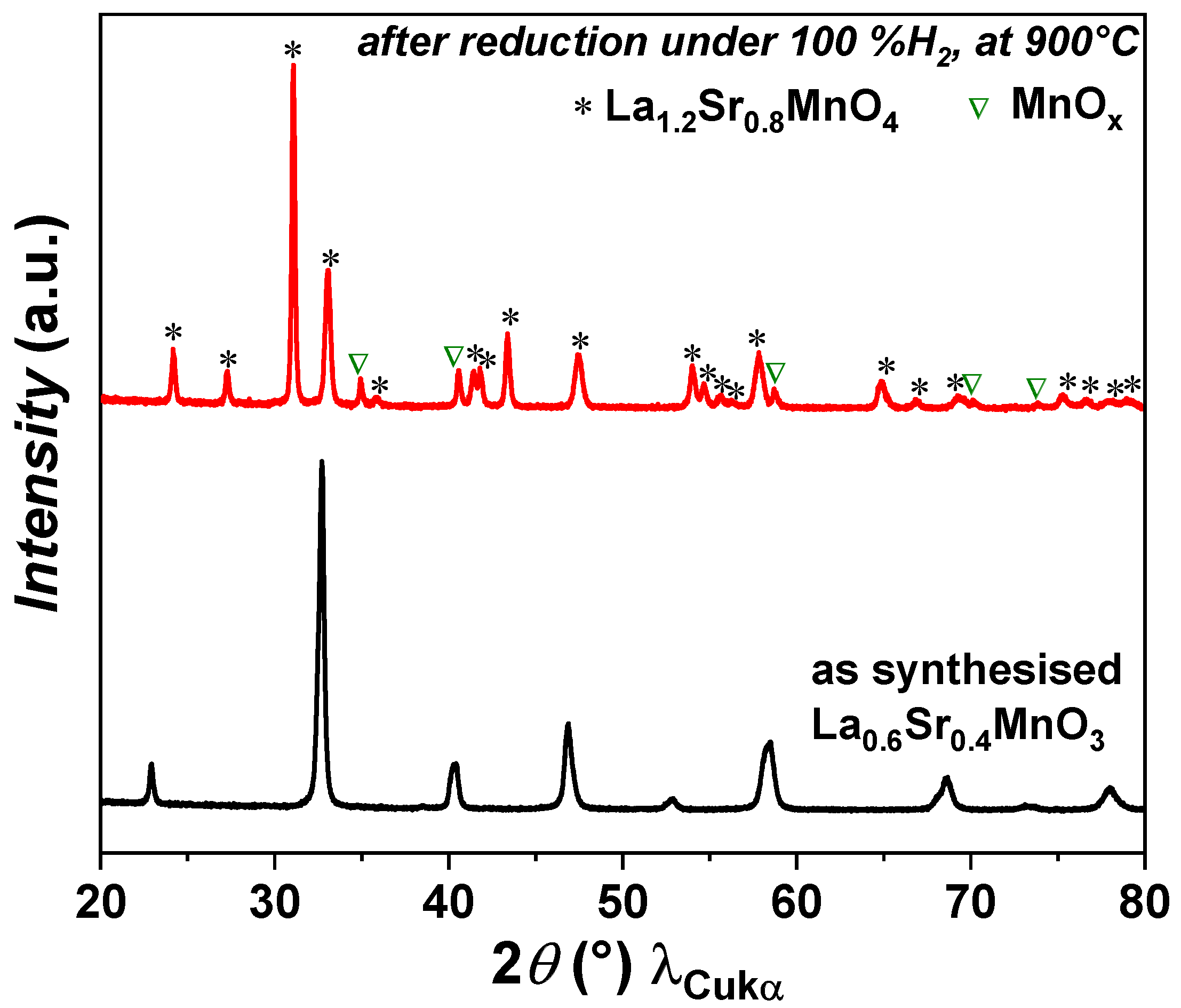
3.1. Phase Identification

The XRD analysis of as-prepared powder shows that the LSM powder is phase pure. The powder was then reduced at 900 °C under pure hydrogen for 6 h. Under a reducing atmosphere, the LSM perovskite phase transforms into a Ruddlesden–Popper (La0.6Sr0.4)2MnO4±δ phase along with a MnOx phase, as shown in Figure 1. The phase transition from perovskite LSM to RP LSM is reversible under a redox environment. This result is in agreement with previously reported results [45]. A similar behaviour was reported for a La0.6Sr0.4Mn0.2Fe0.8O3 (LSMF) perovskite phase, which changes into a La1.2Sr0.8Mn0.4Fe0.6O4 (RP LSMF) phase under a reducing atmosphere with the exsolution of Fe nanoparticles [46]. In the case of LSMF, the phase transformation was also reversible under a redox environment.

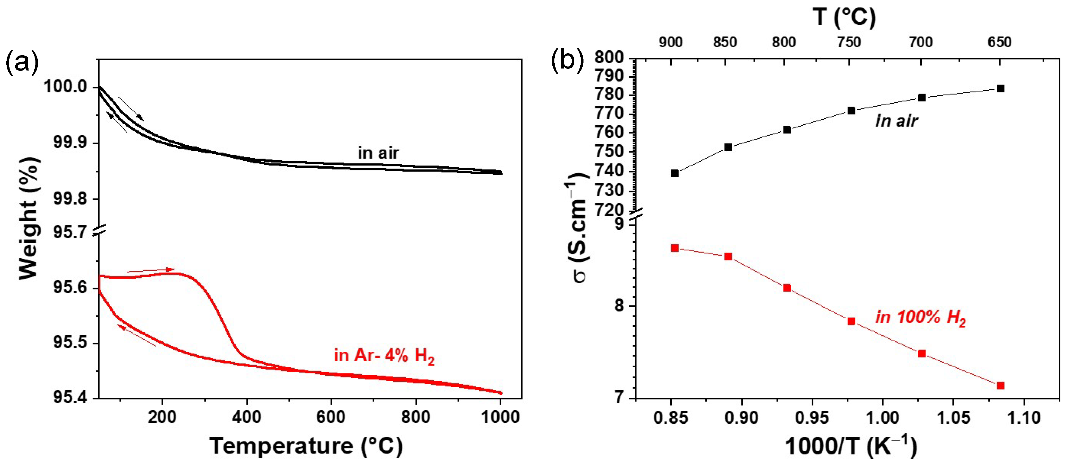
3.2. Thermal Variation of Weight% and DC Conductivity

The thermal variation in weight loss (in %) in air and Ar–4% H2 atmospheres as a function of temperature is shown in Figure 2a. In the air atmosphere, a reversible weight change is observed throughout the temperature range up to 1000 °C. Overall, a weight change of 0.15% is observed. However, in the reducing atmosphere, a slightly different behaviour is observed. In the temperature range of 500–1000 °C, a completely reversible weight change is observed. At lower temperatures below 500 °C, hysteresis is observed, mainly due to different rates of oxygen loss and uptake in the crystal lattice. An overall weight change of 0.22% is observed in the reducing atmosphere, which is slightly higher than in the air atmosphere, indicating a slightly higher oxygen defect formation in RP LSM than in the LSM perovskite phase.
The variations in the total electrical conductivity σ vs. 1000/T under air and 100% H2 atmospheres are shown in Figure 2b. In the air atmosphere, a higher conductivity is observed in the entire temperature range of 650–900 °C than in the reducing atmosphere. In addition, a slight decrease in conductivity with increasing temperature is noticed. For instance, the conductivity value of 784 S·cm−1 was observed at 650 °C, which dropped to 740 S·cm−1 at 900 °C. However, a lower conductivity is observed under a reducing atmosphere. The value of conductivity increases with increasing temperature. A maximum conductivity of 8.7 S·cm−1 was observed at 900 °C. Nevertheless, the conductivity value of LSM under a reducing atmosphere is in the same order of magnitude as that of other perovskite-based fuel electrodes, as shown in Table 1.
The microstructure of the LSM fuel electrode before and after reduction is shown in Figure 3a–d. Figure 3a,b represent the microstructure of the as-prepared electrode sintered at 1150 °C for 1 h in air. The LSM electrode exhibits a porous structure with homogenous particle size distribution and smooth particle surface before reduction. However, after reduction at 900 °C in 100% H2, many nanosized particles (MnOx) were exsolved out and distributed on the surface of RP LSM (Figure 3c,d), which agrees with the XRD data. The EDX elemental mapping of the LSM electrode before and after reduction was also carried out. The SEM image and the corresponding EDX elemental mapping for La (Lα, 4.65 keV), Sr (Lα, 1.81 keV), and Mn (Lα, 0.64 keV) are presented in Figure 4, which also demonstrates the formation of MnOx particles after reduction.

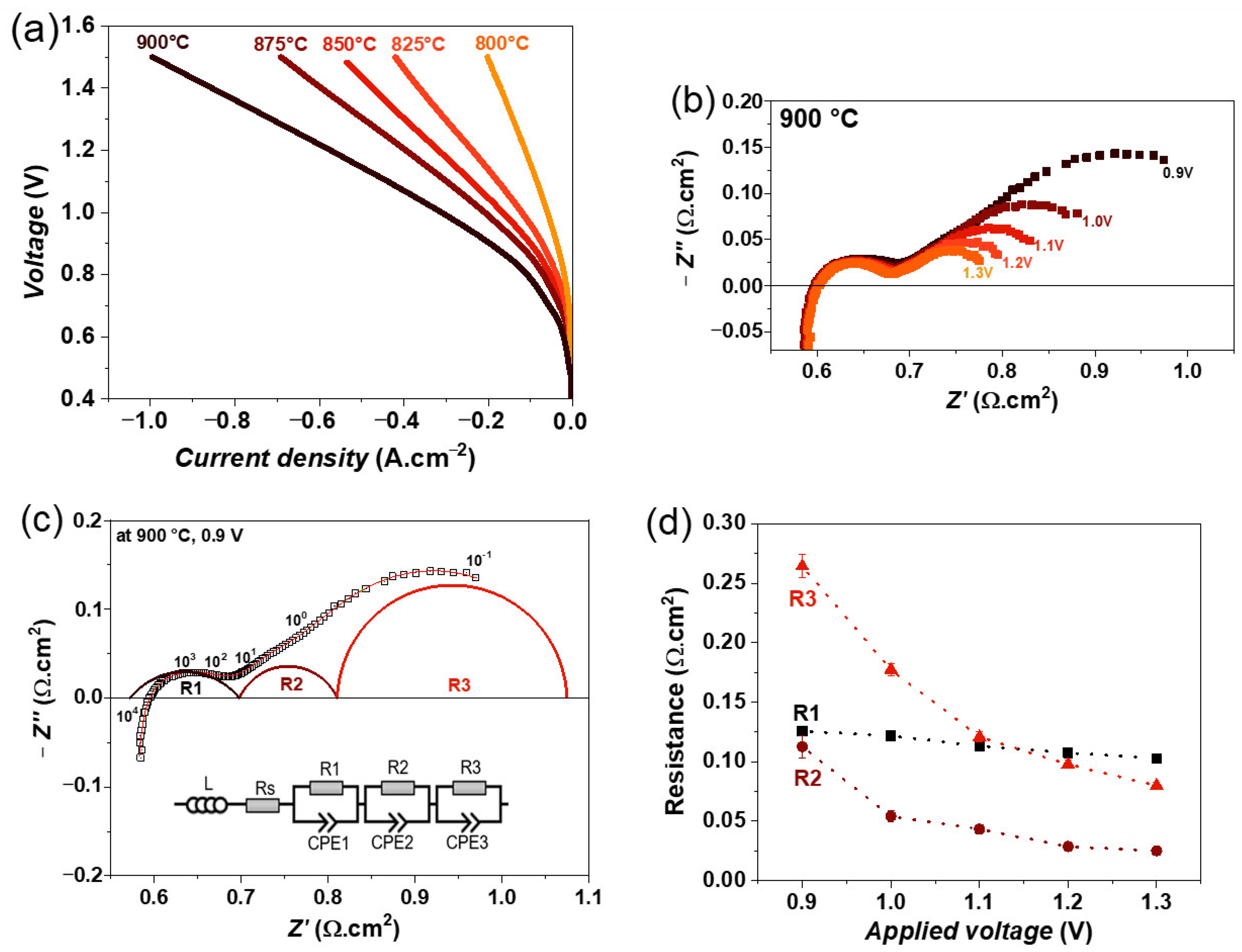
3.3. Single Cell Characterization

For the electrochemical measurement, the single cell was mounted into the measurement setup and heated to 900 °C, with flows of compressed air and N2 on the oxygen and fuel electrode sides, respectively. The flow of N2 at the fuel side was progressively substituted by dry hydrogen (H2) to reduce the perovskite LSM into RP LSM. After complete reduction of the fuel electrode, the OCV under dry conditions (9 nl∙h−1 H2 and 9 nL∙h−1 air, on the fuel electrode side and the oxygen electrode side, respectively) was ≈1.19 V at 900 °C, which is close to the theoretical OCV. The steam electrolysis experiments were then carried out with a gas composition of 50% N2 + 50% H2O. In addition to steam electrolysis, co-electrolysis and CO2-electrolysis experiments were also carried out with 50% CO2 + 50% H2O and 100% CO2 gas flow, respectively.
The iV curves of the single cell were recorded in the temperature range of 800–900 °C with a step of 25 °C and are depicted in Figure 5a. As expected, the cell performance decreases with decreasing temperature due to slower reaction kinetics at lower temperatures. Under steam electrolysis conditions, a maximum current density of 1000 mA·cm−2 at 1.5 V was achieved at 900 °C. This value for the current density is slightly higher than that of the single cell with the state-of-the-art Ni-YSZ electrode. However, a direct comparison of current densities of our cells with those in the literature is difficult because the reported cells have different fuel and oxygen electrodes. For instance, an electrolyte-supported Ni-YSZ/8YSZ/GDC/LSCF single cell shows 910 mA·cm−2 at 1.5 V and 900 °C with a 50%H2 and 50% H2O fuel gas mixture [32]. However, the LSM fuel electrode shows lower performance than the single cell with a Ni-GDC electrode, which shows a current density of 1310 mA·cm−2 at 1.5 V and 900 °C [30,32]. Other perovskite-based materials such as Sr2Fe1.5Mo0.5O6-δ (SFM) also show better performance than the LSM electrode, e.g., the SFM/GDC/YbScSZ/GDC/SFM single cell shows a current density of 1400 mA·cm−2 at 900 °C with a fuel gas mixture of 90% H2O and 10% Ar [52]. It should be mentioned that the better performance of the above-mentioned cells compared with the LSM cell may also be due to the better oxygen electrodes than LSM + YSZ/LSM. The cell performance of some other recently developed fuel electrode materials is compared in Table 2.
The impedance spectra were recorded as a function of the applied voltage from 0.9 to 1.3 V at 900 °C, and their variations are shown in Figure 5b. It can be seen that the polarization resistance (Rp) is decreasing with an increasing electrolysis voltage. In the impedance spectra, mainly two large arcs, one at a high frequency and the other one at a low frequency, are observed, but the major change is observed at the low-frequency arc with applied voltage. Moreover, all these impedance spectra were fitted by three R//CPE elements along with an inductor (L) and series resistance (R), which is the simplest equivalent circuit model that yields a good fit to the data, as confirmed by the lower relative residuals error compared with other equivalent circuit models. The fitting of impedance spectra obtained at 0.9 V is shown in Figure 5c, as an example. The obtained resistances as a function of the electrolysis voltage are plotted in Figure 5d. All three resistances decrease with increasing voltage, but the largest decrease is observed for the resistance R3, indicating that the process associated with this resistance could be related to the charge transfer overlapping with the surface or gas diffusion at the fuel electrode [31,53].
The co-electrolysis experiments were carried out with a fuel gas mixture of 50% CO2 + 50% H2O. The variation in iV curves as a function of temperature is shown in Figure 6a. A maximum current density of 1020 mA·cm−2 at 1.5 V was achieved at 900 °C, which is slightly higher in comparison with steam electrolysis. The slightly higher performance is mainly due to the higher fuel content in the co-electrolysis mode. The maximum current density also decreases with decreasing temperature, similar to steam electrolysis. However, the obtained value is lower than that of Ni-YSZ and Ni-GDC single cells, where current densities of 1060 and 1370 mA·cm−2 at 1.5 V and 900 °C were achieved with a fuel gas composition of 40%CO2, 40%H2O, and 20% CO [30,32].
The impedance spectra as a function of an applied voltage from 0.9 to 1.3 V at 900 °C are shown in Figure 6b. Here as well, the Rp decreases with increasing electrolysis voltage. In the case of co-electrolysis, the impedance spectra were fitted by four R//CPE elements along with an inductor (L) and series resistance (Rs). An additional time constant compared with steam electrolysis indicates a different electrode process during co-electrolysis. Figure 6c shows the fitted impedance spectrum at 0.9 V. The variation in obtained resistances is plotted in Figure 6d. It can be seen that the resistance R1 does not vary with voltage, however, the resistances R2, R3, and R4 decrease with increasing voltage. The largest decrease is observed for resistance R4, which can be associated with the charge transfer process and gas diffusion at the fuel electrode [31,53].
The CO2 electrolysis experiments were carried out with a gas flow of 100% CO2. Figure 7a shows the variation in iV curves as a function of temperature. In this case, a maximum current density of 985 mA·cm−2 at 1.5 V was achieved at 900 °C, which is slightly lower than that of the steam and co-electrolysis conditions. It is worth mentioning that the obtained current density value for the LSM electrode under CO2 electrolysis conditions is higher than that of the state-of-the-art Ni-YSZ electrode, where a current density of 630 mA·cm−2 at 1.5 V and 900 °C was obtained with a fuel gas mixture of 80% CO2 and 20% CO [29,32]. However, the value is lower than that of the Ni-GDC cell with an LSCF oxygen electrode, which has 1160 mA·cm−2 at 1.5 V and 900 °C with a fuel gas mixture of 80% CO2 and 20% CO [29]. However, in this case, the influence of the LSCF oxygen electrode should also be considered, as it performs better than the LSM + YSZ/LSM electrode [54]. Therefore, a higher current density can be expected in our cells when LSCF is used instead of the LSM + YSZ/LSM oxygen electrode.
The impedance spectra as a function of an applied voltage from 0.9 to 1.3 V at 900 °C are shown in Figure 7b. The polarization resistance (Rp) decreases continuously with increasing electrolysis voltage, similar to those of steam or co-electrolysis conditions. In this case, all impedance spectra were also fitted by four R//CPE elements along with an inductor (L) and series resistance (R), similar to the co-electrolysis conditions. The fitting of impedance spectra obtained at 0.9 V, for example, is shown in Figure 7c. The obtained resistances as a function of the electrolysis voltage are plotted in Figure 7d. All four resistances decrease with increasing voltage, but the largest decrease is observed for resistance R4, again suggesting that this low-frequency R4 process may be related to a charge transfer process and gas diffusion at the fuel electrode [31,53].
To further improve the performance of the cell, the fuel electrode was modified by preparing a composite electrode with YSZ and GDC. The LSM + YSZ (50:50 by weight) and LSM + GDC (50:50 by weight) fuel electrodes were deposited on 8YSZ electrolyte support and sintered under the same conditions as the LSM electrode, i.e., at 1150 °C for 1 h in air.
The variation of iV curves for LSM, LSM + GDC, and LSM +YSZ fuel electrodes containing single cells are compared in Figure 8a under steam electrolysis conditions with a 50% N2 and 50% H2O fuel gas mixture. A good cell performance is observed for the LSM + GDC fuel electrode containing a single cell. However, a lower performance is noticed for the LSM + YSZ fuel electrode. For example, under steam electrolysis conditions, current densities of 1030 and 511 mA.cm−2 at 1.5 V are achieved for LSM + GDC and LSM + YSZ fuel electrodes containing single cells, respectively. A similar behaviour is observed for co-electrolysis conditions with a 50% CO2 and 50% H2O fuel gas mixture, as shown in Figure 8b. In any case, the current densities obtained at 1.5 V for these LSM-based electrodes are lower than those of the Ni-GDC electrode containing a single cell [29,30,32].
The impedance spectra of LSM, LSM + GDC, and LSM + YSZ fuel electrode single cells are compared in Figure 8c, under steam electrolysis conditions at 0.9 V and 900 °C. The cell with an LSM + YSZ fuel electrode shows higher ohmic as well as polarization resistance compared with LSM and LSM + GDC single cells. This indicates that the addition of YSZ decreases the overall activity of the fuel electrode, as YSZ is a purely ionic conductor and electrochemically inactive material. Moreover, the reduction in performance could also be related to the overall conductivity of the fuel electrode. The conductivity of LSM under a reducing atmosphere is quite low (~8.0 S·cm−1 at 800 °C under 100% H2 atmosphere) in comparison to conventional Ni-YSZ electrodes (~1000 S·cm−1 at 800 °C, [14]). The mixing of YSZ in the LSM electrode further reduces the overall conductivity of the LSM + YSZ electrode, to an even lower level than the pure LSM electrode and hence significantly reduces the performance of the cell. In the case of the GDC + LSM fuel electrode, GDC is a mixed ionic and electronic conductor and is also electrochemically active [31], and hence, mixing GDC does not affect the overall activity of the electrode. A detailed analysis of the recorded impedance spectra and long-term measurements are in progress and will be the scope of our next publication.

4. Conclusions

In this work, the investigation of alternative fuel electrode materials based on LSM for solid oxide electrolysis cells is carried out. The LSM powder was successfully synthesized and characterized using different techniques, and its stability under air and reducing atmospheres was investigated. Under the reducing atmosphere, the LSM perovskite phase was transformed into a (La0.6Sr0.4)2MnO4±δ Ruddlesden–Popper phase and MnOx. The MnOx phase was then decorated at the surface of the (La0.6Sr0.4)2MnO4±δ phase. The TGA analysis revealed a slightly larger weight change in the reducing atmosphere compared with the air atmosphere. The conductivity of LSM is lower in the reducing atmosphere than in air, however, the conductivity values are in the same range as other perovskite-based fuel electrode materials under reducing conditions.
The electrochemical performance of the single cells with LSM fuel electrodes was investigated under steam electrolysis with 50% N2 + 50% H2O, co-electrolysis with 50% CO2 + 50% H2O, and direct CO2 electrolysis with 100% CO2 gas flow. Thus, current densities of 1000, 1020, and 985 mA·cm−2 were obtained at 1.5 V at 900 °C under steam-, co-, and CO2 electrolysis conditions, respectively, which is lower than an electrolyte-supported Ni-GDC electrode but higher than an electrolyte-supported single cell with a Ni-YSZ electrode. In addition, composite fuel electrodes were also prepared with YSZ and GDC, i.e., LSM + YSZ (50:50 by weight) and LSM + GDC (50:50 by weight), and were investigated under electrolysis conditions. A good cell performance was found for the LSM + GDC fuel electrode containing a single cell; conversely, a lower performance is noticed for the single cell with the LSM + YSZ fuel electrode. For example, under steam electrolysis conditions, current densities of 1030 and 511 mA·cm−2 at 1.5 V are achieved for LSM + GDC and LSM + YSZ fuel electrodes containing single cells, respectively. The long-term test under electrolysis conditions is in progress and will be the subject of further publications.

Author Contributions

Conceptualization, V.V., I.C.V. and L.G.J.d.H.; methodology, V.V., I.C.V. and L.G.J.d.H.; software, V.V., I.C.V., R.-A.E. and L.G.J.d.H.; formal analysis, V.V. and I.C.V.; investigation, V.V.; resources, V.V., I.C.V., R.-A.E. and L.G.J.d.H.; writing—original draft preparation, V.V.; writing—review and editing, V.V., I.C.V., R.-A.E. and L.G.J.d.H.; visualization, V.V., I.C.V. and L.G.J.d.H.; supervision, I.C.V., R.-A.E. and L.G.J.d.H.; All authors have read and agreed to the published version of the manuscript.

Funding

This research received no external funding.

Data Availability Statement

Not applicable.

Acknowledgments

The authors thank the Helmholtz Association for the financial support of the SOC research and development at Forschungszentrum Jülich.

Conflicts of Interest

The authors declare no conflict of interest.

References

  1. Posdziech, O.; Schwarze, K.; Brabandt, J. Efficient hydrogen production for industry and electricity storage via high-temperature electrolysis. Int. J. Hydrogen Energy 2019, 44, 19089–19101. [Google Scholar] [CrossRef]
  2. Doenitz, W.; Schmidberger, R.; Steinheil, E.; Streicher, R. Hydrogen production by high temperature electrolysis of water vapour. Int. J. Hydrogen Energy 1980, 5, 55–63. [Google Scholar] [CrossRef]
  3. Wolf, S.E.; Winterhalder, F.E.; Vibhu, V.; de Haart, L.G.J.; Guillon, O.; Eichel, R.-A.; Menzler, N.H. Solid oxide electrolysis cells–current material development and industrial application. J. Mater. Chem. A 2023, 11, 17977–18028. [Google Scholar] [CrossRef]
  4. Chen, K.; Jiang, S.P. Review—Materials Degradation of Solid Oxide Electrolysis Cells. J. Electrochem. Soc. 2016, 163, F3070–F3083. [Google Scholar] [CrossRef]
  5. Ma, Z.; Zhou, J.; Li, Y.; Liu, C.; Pu, J.; Chen, X. Developments in CO2 Electrolysis of Solid Oxide Electrolysis Cell with Different Cathodes. Fuel Cells 2020, 20, 650–660. [Google Scholar] [CrossRef]
  6. Jensen, S.H.; Larsen, P.H.; Mogensen, M. Hydrogen and synthetic fuel production from renewable energy sources. Int. J. Hydrogen Energy 2007, 32, 3253–3257. [Google Scholar] [CrossRef]
  7. Sala, E.M.; Mazzanti, N.; Mogensen, M.B.; Chatzichristodoulou, C. Current understanding of ceria surfaces for CO2 reduction in SOECs and future prospects–A review. Solid State Ion. 2022, 375, 115833. [Google Scholar] [CrossRef]
  8. Zhang, W.; Zheng, Y.; Yu, B.; Wang, J.; Chen, J. Electrochemical characterization and mechanism analysis of high temperature Co-electrolysis of CO2 and H2O in a solid oxide electrolysis cell. Int. J. Hydrogen Energy 2017, 42, 29911–29920. [Google Scholar] [CrossRef]
  9. Ebbesen, S.D.; Sun, X.; Mogensen, M.B. Understanding the processes governing performance and durability of solid oxide electrolysis cells. Faraday Discuss. 2015, 182, 393–422. [Google Scholar] [CrossRef]
  10. Wolf, S.E.; Vibhu, V.; Tröster, E.; Vinke, I.C.; Eichel, R.-A.; de Haart, L.G.J. Steam Electrolysis vs. Co-Electrolysis: Mechanistic Studies of Long-Term Solid Oxide Electrolysis Cells. Energies 2022, 15, 5449. [Google Scholar] [CrossRef]
  11. Vafaeenezhad, S.; Hanifi, A.R.; Laguna-Bercero, M.A.; Etsell, T.H.; Sarkar, P. Microstructure and long-term stability of Ni–YSZ anode supported fuel cells: A review. Mater. Futures 2022, 1, 042101. [Google Scholar] [CrossRef]
  12. Graves, C.; Ebbesen, S.D.; Jensen, S.H.; Simonsen, S.B.; Mogensen, M.B. Eliminating degradation in solid oxide electrochemical cells by reversible operation. Nat. Mater. 2015, 14, 239–244. [Google Scholar] [CrossRef]
  13. Hauch, A.; Ebbesen, S.D.; Jensen, S.H.; Mogensen, M. Solid Oxide Electrolysis Cells: Microstructure and Degradation of the Ni/Yttria-Stabilized Zirconia Electrode. J. Electrochem. Soc. 2008, 155, B1184. [Google Scholar] [CrossRef]
  14. Jiang, S.P.; Chan, S.H. A review of anode materials development in solid oxide fuel cells. J. Mater. Sci. 2004, 39, 4405–4439. [Google Scholar] [CrossRef]
  15. Park, B.-K.; Scipioni, R.; Cox, D.; Barnett, S.A. Enhancement of Ni–(Y2O3)0.08(ZrO2)0.92 fuel electrode performance by infiltration of Ce0.8Gd0.2O2−δ nanoparticles. J. Mater. Chem. A 2020, 8, 4099–4106. [Google Scholar] [CrossRef]
  16. Trini, M.; Hauch, A.; De Angelis, S.; Tong, X.; Hendriksen, P.V.; Chen, M. Comparison of microstructural evolution of fuel electrodes in solid oxide fuel cells and electrolysis cells. J. Power Sources 2020, 450, 227599. [Google Scholar] [CrossRef]
  17. Hauch, A.; Blennow, P. Solid oxide electrolysis cells–Interplay between operating conditions, fuel electrode overpotential and degradation. Solid State Ion. 2023, 391, 116127. [Google Scholar] [CrossRef]
  18. Ebbesen, S.D.; Jensen, S.H.; Hauch, A.; Mogensen, M.B. High Temperature Electrolysis in Alkaline Cells, Solid Proton Conducting Cells, and Solid Oxide Cells. Chem. Rev. 2014, 114, 10697–10734. [Google Scholar] [CrossRef]
  19. Fu, Q.; Schefold, J.; Brisse, A.; Nielsen, J.U. Durability Testing of a High-Temperature Steam Electrolyzer Stack at 700 °C. Fuel Cells 2014, 14, 395–402. [Google Scholar] [CrossRef]
  20. Mougin, J.; Mansuy, A.; Chatroux, A.; Gousseau, G.; Petitjean, M.; Reytier, M.; Mauvy, F. Enhanced Performance and Durability of a High Temperature Steam Electrolysis Stack. Fuel Cells 2013, 13, 623–630. [Google Scholar] [CrossRef]
  21. Ebbesen, S.D.; Graves, C.; Mogensen, M. Production of Synthetic Fuels by Co-Electrolysis of Steam and Carbon Dioxide. Int. J. Green Energy 2009, 6, 646–660. [Google Scholar] [CrossRef]
  22. Budiman, R.A.; Konishi, R.; Bisaka, N.; Yashiro, K.; Kawada, T. Time-Dependence of Microstructural Evolution and Performance Degradation of Ni/YSZ Electrode in Co-Electrolysis SOEC. ECS Trans. 2023, 111, 1509. [Google Scholar] [CrossRef]
  23. Rorato, L.; Shang, Y.; Yang, S.; Hubert, M.; Couturier, K.; Zhang, L.; Vulliet, J.; Chen, M.; Laurencin, J. Understanding the Ni Migration in Solid Oxide Cell: A Coupled Experimental and Modeling Approach. J. Electrochem. Soc. 2023, 170, 034504. [Google Scholar] [CrossRef]
  24. Shang, Y.; Smitshuysen, A.L.; Yu, M.; Liu, Y.; Tong, X.; Jørgensen, P.S.; Rorato, L.; Laurencin, J.; Chen, M. 3D microstructural characterization of Ni/yttria-stabilized zirconia electrodes during long-term CO2 electrolysis. J. Mater. Chem. A 2023, 11, 12245–12257. [Google Scholar] [CrossRef]
  25. Mogensen, M.B.; Chen, M.; Frandsen, H.L.; Graves, C.; Hauch, A.; Hendriksen, P.V.; Jacobsen, T.; Jensen, S.H.; Skafte, T.L.; Sun, X. Ni migration in solid oxide cell electrodes: Review and revised hypothesis. Fuel Cells 2021, 21, 415–429. [Google Scholar] [CrossRef]
  26. Schefold, J.; Brisse, A.; Poepke, H. 23,000 h steam electrolysis with an electrolyte supported solid oxide cell. Int. J. Hydrogen Energy 2017, 42, 13415–13426. [Google Scholar] [CrossRef]
  27. Singh, V.; Muroyama, H.; Matsui, T.; Hashigami, S.; Inagaki, T.; Eguchi, K. Feasibility of alternative electrode materials for high temperature CO2 reduction on solid oxide electrolysis cell. J. Power Sources 2015, 293, 642–648. [Google Scholar] [CrossRef]
  28. Léon, A.; Micero, A.; Ludwig, B.; Brisse, A. Effect of scaling-up on the performance and degradation of long-term operated electrolyte supported solid oxide cell, stack and module in electrolysis mode. J. Power Sources 2021, 510, 230346. [Google Scholar] [CrossRef]
  29. Unachukwu, I.D.; Vibhu, V.; Uecker, J.; Vinke, I.C.; Eichel, R.-A.; de Haart, L.G.J. Electrochemical impedance analysis and degradation behavior of a Ni-GDC fuel electrode containing single cell in direct CO2 electrolysis. J. CO2 Util. 2023, 69, 102423. [Google Scholar] [CrossRef]
  30. Unachukwu, I.D.; Vibhu, V.; Vinke, I.C.; Eichel, R.-A.; de Haart, L.G.J. Electrochemical and degradation behaviour of single cells comprising Ni-GDC fuel electrode under high temperature steam- and co-electrolysis conditions. J. Power Sources 2023, 556, 232436. [Google Scholar] [CrossRef]
  31. Uecker, J.; Unachukwu, I.D.; Vibhu, V.; Vinke, I.C.; Eichel, R.-A.; de Haart, L.G.J. Performance, electrochemical process analysis and degradation of gadolinium doped ceria as fuel electrode material for solid oxide electrolysis cells. Electrochim. Acta 2023, 452, 142320. [Google Scholar] [CrossRef]
  32. Unachukwu, I.D.; Vibhu, V.; Uecker, J.; Vinke, I.C.; Eichel, R.-A.; de Haart, L.G.J. Comparison of the Electrochemical and Degradation Behaviour of Ni-YSZ and Ni-GDC Electrodes Under Steam, Co- and CO2 Electrolysis. ECS Trans. 2023, 111, 1445. [Google Scholar] [CrossRef]
  33. Vibhu, V.; Vinke, I.C.; Zaravelis, F.; Neophytides, S.G.; Niakolas, D.K.; Eichel, R.-A.; de Haart, L.G.J. Performance and Degradation of Electrolyte-Supported Single Cell Composed of Mo-Au-Ni/GDC Fuel Electrode and LSCF Oxygen Electrode during High Temperature Steam Electrolysis. Energies 2022, 15, 2726. [Google Scholar] [CrossRef]
  34. Bastidas, D.M.; Tao, S.; Irvine, J.T.S. A symmetrical solid oxide fuel cell demonstrating redox stable perovskite electrodes. J. Mater. Chem. 2006, 16, 1603–1605. [Google Scholar] [CrossRef]
  35. Slater, P.R.; Fagg, D.P.; Irvine, J.T.S. Synthesis and electrical characterisation of doped perovskite titanates as potential anode materials for solid oxide fuel cells. J. Mater. Chem. 1997, 7, 2495–2498. [Google Scholar] [CrossRef]
  36. Zhou, X.; Yan, N.; Chuang, K.T.; Luo, J. Progress in La-doped SrTiO3 (LST)-based anode materials for solid oxide fuel cells. RSC Adv. 2014, 4, 118–131. [Google Scholar] [CrossRef]
  37. Liu, Q.; Yang, C.; Dong, X.; Chen, F. Perovskite Sr2Fe1.5Mo0.5O6−δ as electrode materials for symmetrical solid oxide electrolysis cells. Int. J. Hydrogen Energy 2010, 35, 10039–10044. [Google Scholar] [CrossRef]
  38. Sengodan, S.; Choi, S.; Jun, A.; Shin, T.H.; Ju, Y.-W.; Jeong, H.Y.; Shin, J.; Irvine, J.T.S.; Kim, G. Layered oxygen-deficient double perovskite as an efficient and stable anode for direct hydrocarbon solid oxide fuel cells. Nat. Mater. 2015, 14, 205–209. [Google Scholar] [CrossRef]
  39. Tao, S.; Irvine, J.T.S. Study on the structural and electrical properties of the double perovskite oxide SrMn0.5Nb0.5O3−δ. J. Mater. Chem. 2002, 12, 2356–2360. [Google Scholar] [CrossRef]
  40. Ishihara, T.; Wang, S.; Wu, K.-T. Highly active oxide cathode of La(Sr)Fe(Mn)O3 for intermediate temperature CO2 and CO2-H2O co-electrolysis using LSGM electrolyte. Solid State Ion. 2017, 299, 60–63. [Google Scholar] [CrossRef]
  41. Jin, C.; Yang, C.; Zhao, F.; Cui, D.; Chen, F. La0.75Sr0.25Cr0.5Mn0.5O3 as hydrogen electrode for solid oxide electrolysis cells. Int. J. Hydrogen Energy 2011, 36, 3340–3346. [Google Scholar] [CrossRef]
  42. Mizusaki, J.; Yonemura, Y.; Kamata, H.; Ohyama, K.; Mori, N.; Takai, H.; Tagawa, H.; Dokiya, M.; Naraya, K.; Sasamoto, T.; et al. Electronic conductivity, Seebeck coefficient, defect and electronic structure of nonstoichiometric La1−xSrxMnO3. Solid State Ion. 2000, 132, 167–180. [Google Scholar] [CrossRef]
  43. Lee, H.-K. Electrochemical characteristics of La1−xSrxMnO3 for solid oxide fuel cell. Mater. Chem. Phys. 2003, 77, 639–646. [Google Scholar] [CrossRef]
  44. Filonova, E.; Pikalova, E. Overview of Approaches to Increase the Electrochemical Activity of Conventional Perovskite Air Electrodes. Materials 2023, 16, 4967. [Google Scholar] [CrossRef]
  45. Mizusaki, J.; Tagawa, H.; Naraya, K.; Sasamoto, T. Nonstoichiometry and thermochemical stability of the perovskite-type La1−xSrxMnO3−δ. Solid State Ion. 1991, 49, 111–118. [Google Scholar] [CrossRef]
  46. Chung, Y.S.; Kim, T.; Shin, T.H.; Yoon, H.; Park, S.; Sammes, N.M.; Kim, W.B.; Chung, J.S. In situ preparation of a La1.2Sr0.8Mn0.4Fe0.6O4 Ruddlesden–Popper phase with exsolved Fe nanoparticles as an anode for SOFCs. J. Mater. Chem. A 2017, 5, 6437–6446. [Google Scholar] [CrossRef]
  47. Tao, S.; Irvine, J.T.S. Synthesis and Characterization of  (La0.75Sr0.25)Cr0.5Mn0.5O3−δ, a Redox-Stable, Efficient Perovskite Anode for SOFCs. J. Electrochem. Soc. 2004, 151, A252. [Google Scholar] [CrossRef]
  48. Qin, Q.; Xie, K.; Wei, H.; Qi, W.; Cui, J.; Wu, Y. Demonstration of efficient electrochemical biogas reforming in a solid oxide electrolyser with titanate cathode. RSC Adv. 2014, 4, 38474–38483. [Google Scholar] [CrossRef]
  49. Wolf, S.E.; Vibhu, V.; Coll, C.L.; Eyckeler, N.; Vinke, I.C.; Eichel, R.-A.; de Haart, L.G.J. Long-Term Stability of Perovskite-Based Fuel Electrode Material Sr2Fe2-XMoxO6−δ–GDC for Enhanced High-Temperature Steam and CO2 Electrolysis. ECS Trans. 2023, 111, 2119. [Google Scholar] [CrossRef]
  50. Marrero-López, D.; Peña-Martínez, J.; Ruiz-Morales, J.C.; Pérez-Coll, D.; Aranda, M.A.G.; Núñez, P. Synthesis, phase stability and electrical conductivity of Sr2MgMoO6−δ anode. Mater. Res. Bull. 2008, 43, 2441–2450. [Google Scholar] [CrossRef]
  51. Ge, B.; Ma, J.T.; Ai, D.; Deng, C.; Lin, X.; Xu, J. Sr2FeNbO6 Applied in Solid Oxide Electrolysis Cell as the Hydrogen Electrode: Kinetic Studies by Comparison with Ni-YSZ. Electrochim. Acta 2015, 151, 437–446. [Google Scholar] [CrossRef]
  52. Bernadet, L.; Moncasi, C.; Torrell, M.; Tarancón, A. High-performing electrolyte-supported symmetrical solid oxide electrolysis cells operating under steam electrolysis and co-electrolysis modes. Int. J. Hydrogen Energy 2020, 45, 14208–14217. [Google Scholar] [CrossRef]
  53. Sandoval, M.V.; Cardenas, C.; Capoen, E.; Roussel, P.; Pirovano, C.; Gauthier, G.H. Performance of La0.5Sr1.5MnO4±δ Ruddlesden-Popper manganite as electrode material for symmetrical Solid Oxide Fuel Cells. Part B. The Hydrogen Oxidation Reaction. Electrochim. Acta 2020, 353, 136494. [Google Scholar] [CrossRef]
  54. Laguna-Bercero, M.A.; Kilner, J.A.; Skinner, S.J. Performance and Characterization of (La, Sr)MnO3/YSZ and La0.6Sr0.4Co0.2Fe0.8O3 Electrodes for Solid Oxide Electrolysis Cells. Chem. Mater. 2010, 22, 1134–1141. [Google Scholar] [CrossRef]
Figure 1. XRD patterns of LSM powder before and after reduction.
Energies 16 07115 g001
Figure 2. Thermal variation of weight% and DC conductivity in air and reducing atmosphere.
Energies 16 07115 g002
Figure 3. SEM images of the LSM electrode after sintering at 1150 °C for 1h in air (a,b) before reduction, and (c,d) after reduction at 900 °C in 100% H2.
Energies 16 07115 g003
Figure 4. SEM images and elemental mapping of the LSM electrode before and after reduction at 900 °C in 100% H2.
Energies 16 07115 g004
Figure 5. (a) iV characteristics of single cell containing LSM fuel electrode as a function of temperature, (b) variation of impedance spectra as a function of electrolysis voltage from 0.9 to 1.3 V, (c) fitting of impedance spectrum obtained at 0.9 V using equivalent circuit model, and (d) variation of obtained resistances as a function of electrolysis voltage at 900 °C, with 50% N2 and 50% H2O feed gas mixture.
Energies 16 07115 g005
Figure 6. (a) iV characteristics of single cell containing LSM fuel electrode as a function of temperature, (b) variation of impedance spectra as a function of electrolysis voltage from 0.9 to 1.3 V, (c) fitting of impedance spectrum obtained at 0.9 V using equivalent circuit model, and (d) variation of obtained resistances as a function of electrolysis voltage at 900 °C, with 50% CO2 and 50% H2O feed gas mixture.
Energies 16 07115 g006
Figure 7. (a) iV characteristics of single cell containing LSM fuel electrode as a function of temperature, (b) variation of impedance spectra as a function of electrolysis voltage from 0.9 to 1.3 V, (c) fitting of impedance spectrum obtained at 0.9 V using equivalent circuit model, and (d) variation of obtained resistances as a function of electrolysis voltage at 900 °C, with 100% CO2 gas flow.
Energies 16 07115 g007
Figure 8. iV characteristics of single cells containing LSM, LSM + GDC, and LSM +YSZ fuel electrodes at 900 °C with (a) 50% N2 and 50% H2O for steam electrolysis, and (b) 50% N2 and 50% CO2 for co-electrolysis, and (c) the impedance spectra at OCV with 50% N2 and 50% H2O.
Energies 16 07115 g008
Table 1. Electrical conductivity values of Perovskite-based materials under air and reducing conditions.
MaterialsT (°C)σ (Air),
S·cm−1
σ (Reducing Conditions),
S·cm−1
Ref.
LSCM
(La0.75Sr0.25)Cr0.5Mn0.5O3-δ
90038.61.49 (in 5% H2/Ar)[47]
LSMF
La0.6Sr0.4Mn0.2Fe0.8O3
80050.32.8 (in 20% H2/N2)[46]
LST
La0.2Sr0.8TiO3
8000.71.1 (in 5% H2/Ar)[48]
Fe doped LST8000.581.54 (in 5% H2/Ar)[48]
SFM
Sr2Fe1.5Mo0.5O6-δ
9009.214.6 (in 100% H2)[49]
Sr2Fe1.0Mo1.0O6-δ9003.513.5 (in 100%H2)[49]
Sr2MgMoO6−δ8003 × 10−30.8 (in 5% H2/Ar)[50]
Sr2FeNbO6−δ8500.052.22 (wet 20% H2)[51]
LSM9007408.7 (100% H2)This work.
Table 2. Performance of different electrolyte-supported single cells under electrolysis conditions.
Electrolyte Supported
Single Cells
Fuel Gas
Composition
Current Density
(A·cm−2) at 900 °C
Ref.
Sr2Fe1.5Mo0.5O6-δ (SFM)/GDC/YbScSZ/GDC/SFM90/10 of H2O/Ar1.4 A.cm−2 at 1.3 V[52]
Sr2Fe1.5Mo0.5O6-δ (SFM)/GDC/YbScSZ/GDC/SFM75/25 of H2O/CO21.1 A.cm−2 at 1.3 V[52]
Sr2Fe1.5Mo0.5O6-δ (SFM)/GDC/YSZ/GDC/LSCF50/50 of H2O/H21.42 A·cm−2 at 1.5 V[49]
Sr2Fe1.0Mo1.0O6-δ (SFM)/GDC/YSZ/GDC/LSCF50/50 of H2O/H21.22 A·cm−2 at 1.5 V[49]
Ni-GDC/8YSZ/GDC/LSCF50/50 of H2O/H21.31 A·cm−2 at 1.5 V[30]
Ni-GDC/8YSZ/GDC/LSCF40/40/20 of H2O/CO2/CO1.37 A·cm−2 at 1.5 V[30]
Ni-GDC/8YSZ/GDC/LSCF80/20 of CO2/CO1.16 A·cm−2 at 1.5 V[29,32]
Ni-YSZ/8YSZ/GDC/LSCF50/50 of H2O/H20.91 A·cm−2 at 1.5 V[32]
Ni-YSZ/8YSZ/GDC/LSCF40/40/20 of H2O/CO2/CO1.06 A·cm−2 at 1.5 V[32]
Ni-YSZ/8YSZ/GDC/LSCF80/20 of CO2/CO0.63 A·cm−2 at 1.5 V[29,32]
GDC/8YSZ/GDC/LSCF50/50 of H2O/H20.91 A·cm−2 at 1.5 V[31]
GDC/8YSZ/GDC/LSCF40/40/20 of H2O/CO2/CO0.97 A·cm−2 at 1.5 V[31]
La0.6Sr0.4Fe0.8Mn0.2O3-δ (LSFM)/LSGM/Ba0.6La0.4CoO3–δ(BLC)50/1/49 of CO2/CO/Ar0.52 A·cm−2 at 1.6 V[40]
LSM/8YSZ/LSM + YSZ/LSM50/50 of H2O/N21 A·cm−2 at 1.5 VThis
work
LSM/8YSZ/LSM + YSZ/LSM50/50 of H2O/CO21.02 A·cm−2 at 1.5 VThis
work.
LSM/8YSZ/LSM + YSZ/LSM100% CO20.98 A·cm−2 at 1.5 VThis
work.
Disclaimer/Publisher’s Note: The statements, opinions and data contained in all publications are solely those of the individual author(s) and contributor(s) and not of MDPI and/or the editor(s). MDPI and/or the editor(s) disclaim responsibility for any injury to people or property resulting from any ideas, methods, instructions or products referred to in the content.

