Article

Evaluation of the Optional Wideband Accuracy of Inductive Current Transformers in Accordance with the Standard IEC 61869-1 Ed.2

Institute of Mechatronics and Information Systems, Lodz University of Technology, 90-537 Lodz, Poland
*
Author to whom correspondence should be addressed.
Energies 2023, 16(20), 7206; https://doi.org/10.3390/en16207206
Submission received: 6 September 2023 / Revised: 7 October 2023 / Accepted: 11 October 2023 / Published: 23 October 2023
(This article belongs to the Special Issue Condition Monitoring of Power System Components 2024)

Abstract

:
This paper presents the evaluation of tested inductive CTs’ accuracy for distorted current harmonics in accordance with the optional accuracy class WB1 introduced by the new edition of the standard IEC 61869-1 published in the year 2023. The tests were performed in compliance with the interpretation sheet IEC 61869-2:2012/ISH1:2022. Therefore, the resistive and the resistive–inductive loads of the secondary winding of tested inductive CTs were used, as this was required for the given test conditions. The results indicate that the units designed for the transformation of a sinusoidal current of a frequency of 50 Hz ensure the high wideband transformation accuracy of the distorted current harmonics, as demanded by the power quality monitoring and distorted electrical power and energy requirements. The key to this is proper design using modern magnetic material(s) for the magnetic core and its oversizing in relation to the requirements for a given accuracy class defined for the transformation of sinusoidal currents with a rated frequency. Both tested inductive CTs with a rated primary current RMS value equal to 300 A, class 0.2 and 0.5, ensured compliance with the requirements of the WB1 wideband accuracy class.

1. Introduction

Power quality is a critical aspect of modern power systems and determines safe and efficient operation of the connected electrical equipment and apparatus [1,2,3,4,5]. This involves RMS value fluctuation, three-phase asymmetry, frequency variation and distortion of voltage and current. Inductive instrument transformers play a fundamental role in monitoring power network current and voltage. Inductive current transformers (CTs) are used in power systems to adjust large currents to an appropriate level for measuring, protection and control equipment [6,7,8]. However, their use for the transformation of distorted currents requires additional tests over a wide frequency range, particularly concerning the specification of their accuracy for harmonics [5,9,10,11,12,13,14,15,16]. This ensures proper power measurement and its quality monitoring in the condition of a distorted current and voltage. The standard IEC 61869-1 in the new version from the year 2023 provides requirements and guidelines for the evaluation of the optional wideband accuracy classes for inductive CTs [17]. These requirements are similar to those previously defined in the standard IEC 61869-6 for low-power instrument transformers [18]. There are five extensions of the accuracy classes concerning higher harmonics:
  • WB0—covering harmonics up to and including the 13th harmonic.
  • WB1—encompassing harmonic frequencies up to and including 3 kHz.
  • WB2—including harmonic frequencies up to 20 kHz.
  • WB3—spanning harmonic frequencies up to 150 kHz.
  • WB4—applicable for wide-bandwidth applications up to 500 kHz.
Consequently, the accuracy class of the instrument transformer may be defined, for example, as 0.5-WB1.
This paper presents the evaluation of the tested inductive CTs’ accuracy for harmonics of a distorted current in accordance with the optional accuracy class WB1 introduced by the new edition of the standard IEC 61869-1 [17]. It has been shown that it is not necessary to use error compensation techniques to obtain high wideband transformation accuracy for the transformation of a sinusoidal current with a frequency of 50 Hz into low-voltage inductive CTs manufactured by an international company [12,19,20,21]. The evaluation of wideband transformation accuracy was performed for a distorted current composed of a fundamental component with a frequency of 50 Hz and a series of higher harmonics with frequencies ranging from 100 Hz to 3 kHz. Furthermore, no significant self-distortion of the secondary current related to the generation of the low-order higher harmonics resulting from the nonlinearity of the magnetic core’s magnetization characteristic was detected in the case of either tested unit [19,22]. Moreover, the tests were performed in accordance with the interpretation sheet IEC 61869-2:2012/ISH1:2022 [23]. Therefore, the resistive and the resistive–inductive (with a power factor equal to 0.8) loads of the secondary winding of the tested inductive CTs were used, as required by the standard IEC 61869-2 due to their rated apparent power. The main conclusion of this paper is that the inductive CTs designed for the transformation of sinusoidal currents of 50 Hz frequency ensure the high wideband transformation accuracy of distorted current harmonics, as demanded by the power quality monitoring and distorted electrical power and energy requirements [3,4,24,25,26,27,28,29,30,31].

2. Measuring Circuits and Tested CTs

The transformation accuracy of the distorted primary current produced by the tested window-type inductive CTs was determined with the utilization of the ampere-turn method. Therefore, an additional primary winding with a number of turns equal to the rated current ratio was made [32]. In this case, its rated primary current was equal to the rated primary current of the secondary winding. This method eliminates the necessity of using a high-current power supply system.
The value of the current error for the hk harmonic could be determined using the following equation:
Δ I hk = I 2 hk I 1 Ahk I 1 Ahk · 100 %
where I2hk is the RMS value of the secondary current hk harmonic of the TCT and I1hk is the RMS value of the current hk harmonic in the additional primary winding of the TCT.
The values of phase displacement for the hk harmonic were determined as the phase angle between same-order hk harmonics of the distorted currents in the additional primary winding and in the secondary winding of the TCT. The values of phase displacement were determined using the following equation:
δ φ hk = φ 2 hk φ 1 hk
where φ1hk is the phase angle of the hk harmonics of the distorted current in the additional primary winding in relation to the reference voltage and φ2hk is the phase angle of the hk harmonics of the distorted current in the secondary winding in relation to the reference voltage.
The utilization of the digital power meter (DPM) enabled Fast Fourier Transform (FFT) to be performed for the measured currents, which allowed the RMS values and phase angles of their harmonics to be determined. In Figure 1, the measuring circuit used to determine the values of the current error and phase displacement for the transformation of distorted current harmonics using the tested CTs is presented.
The TCTs were supplied with a distorted current composed of a fundamental component with a frequency of 50 Hz and a series of higher harmonics with a frequency ranging from 100 Hz to 3 kHz. The percentage value of each higher harmonic was equal to 5%. The accuracy tests were performed for 100% and 25% of the rated load of the TCT’s secondary winding. In the case of the CT with a rated load equal to 2.5 VA, the lowest value of the load was equal to 1 VA, in accordance with the interpretation sheet IEC 61869-2:2012/ISH1:2022 [23]. Moreover, if the load of the secondary winding was lower than 5 VA, the tests were conducted for a power factor equal to 1. The accuracy was evaluated for two manufactured inductive CTs and 5%, 20%, 100% and 120% of their rated primary current. The first unit was characterized by a rated current ratio equal to 300 A/5 A, and the rated apparent load of the secondary winding was equal to 5 VA. Moreover, its accuracy class, as defined for the transformation of a sinusoidal current with a frequency of 50 Hz, was 0.5. The second one was specified as 300 A/1 A, 2.5 VA, accuracy class 0.2.

3. Wideband Accuracy of the TCTs

3.1. Results for TCT 300 A/5 A Class 0.5

In accordance with the standard IEC 61869-2, the first step of the laboratory studies was to perform the transformation accuracy tests for a sinusoidal current of a rated frequency equal to 50 Hz [33]. The determined values of the current error and phase displacement for the TCT 300 A/5 A class 0.5 and their limits in accordance with the standard IEC 61869-2 are presented in Table 1.
The TCT 300 A/5 A meets the requirements of class 0.5 as defined by the standard IEC 61869-2 [33]. Moreover, the positive values of the current error indicate that the TCT was corrected. Therefore, the number of turns of the secondary winding was reduced in relation to the rated current ratio. The second step was to determine the values of the current error and phase displacement at harmonics during the transformation of the distorted primary current.
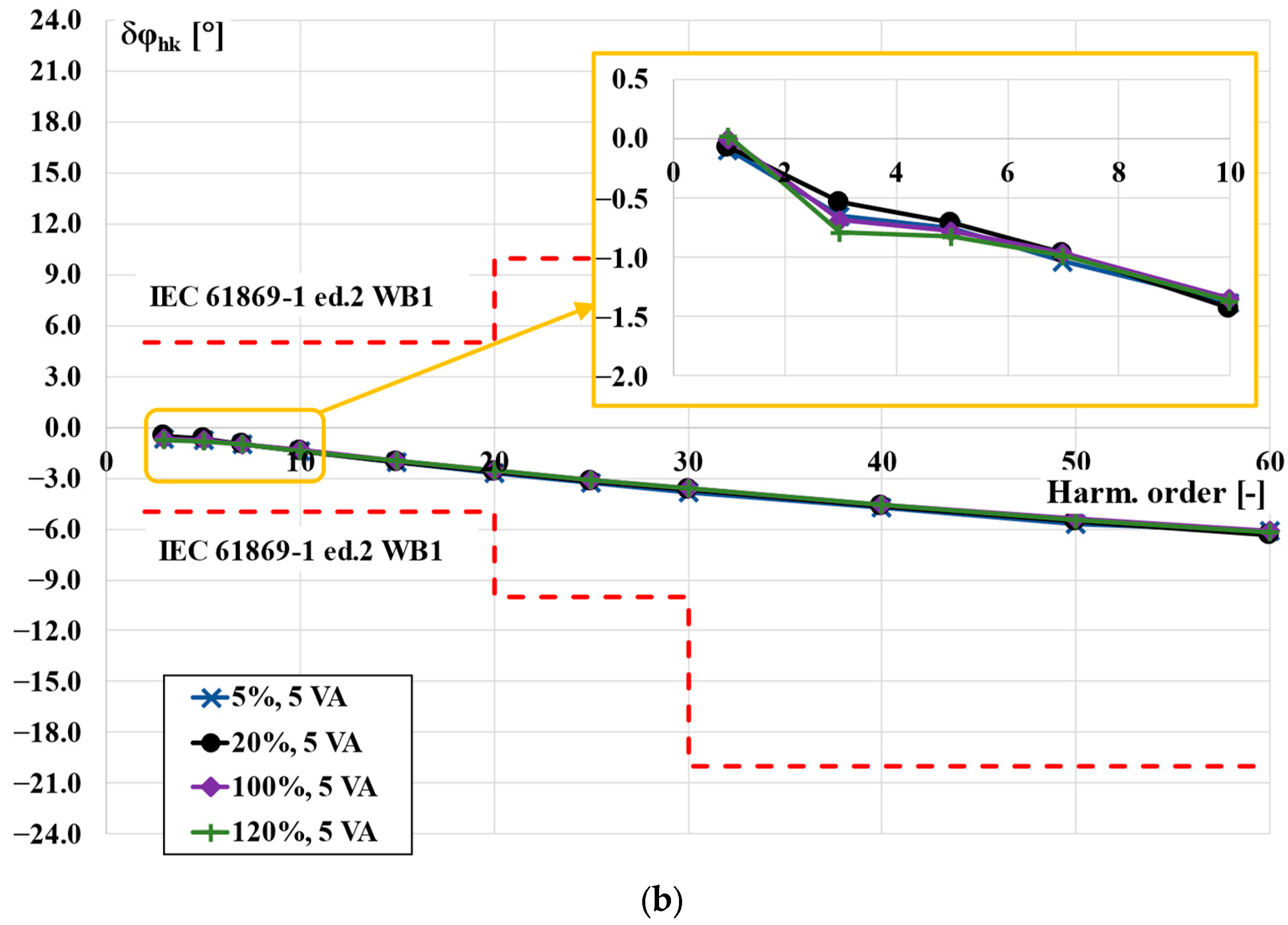
The results for the secondary winding with a rated apparent load power equal to 5 VA and a power factor equal to 0.8 ind. are presented in Figure 2. Moreover, close-ups on the results for harmonics from the 1st to 10th order are presented for evaluation of the self-generation phenomenon of the tested inductive CT. The maximum permissible values of the current error and phase displacement defined by the optional accuracy class WB1 in accordance with the standard IEC 61869-1 ed.2 are also provided [17].
The reactance of the load of the secondary winding caused deterioration of the accuracy with increasing frequency of the transformed higher harmonic. This resulted from the increased RMS value of the secondary voltage with the increased order of the transformed higher harmonic and thus increased apparent power of the secondary winding load [10,11,20]. Nevertheless, the measured values of the current error and phase displacement in the entire frequency range considered did not exceeded the limits defined for the optional accuracy class WB1 in the standard IEC 61869-1 ed.2 [17].
The problem of the additional secondary current distortion by the inductive CT is caused by the nonlinearity of the magnetization characteristic of its magnetic core. This results in self-generation of low-order higher harmonics. Their level depends mainly on the RMS value of the main component and third higher harmonic as well as their mutual phase angle. Moreover, the intensification of this phenomenon is associated with increased values of the secondary current load and its inductive power factor, which cause an increase in the magnetic flux density in the inductive CT’s magnetic core and thus results in movement of its operating point on the magnetization characteristic towards saturation. The self-generation phenomenon is also reflected in the values of the current error and phase displacement of the transformed low-order higher harmonics. This means that if the phase angle of the transformed higher harmonic is properly adjusted relatively to the main component, the most negative and the most positive values of the current error and phase displacement will be determined [5]. Therefore, wideband accuracy tests for the transformation of the low-order higher harmonic were performed for its various phase angles in relation to the fundamental component of the distorted current from 0° to 360°, adjusted in at most 10° steps.
The values of the current error and phase displacement at harmonics for the transformation of the distorted primary current using the TCT 300 A/5 A class 0.5 determined with 25% of the rated load are presented in Figure 3.
Twenty-five percent of the rated load of the TCT was equal to 1.25 VA. Therefore, in accordance with the interpretation sheet IEC 61869-2:2012/ISH1:2022, the power factor of the load used was equal to 1 [23]. In this case, the increase in the values of the current error and phase displacement with the order of transformed higher harmonic was not detectable. The requirements of the WB1 optional accuracy class were also fulfilled with a greater reserve. Taking into consideration the results presented in Figure 2 and Figure 4, the accuracy class of the TCT was determined to be 0.5-WB1.

3.2. Results for TCT 300 A/5 A Class 0.2

The rated load apparent power of the second tested inductive CT was equal to 2.5 VA. Therefore, during the evaluation of its transformation accuracy, the resistance load had to be applied to the secondary winding. The values obtained for the current error and phase displacement for the transformation of a sinusoidal current with a 50 Hz frequency using the TCT 300 A/5 A class 0.2 are presented in Table 2.
The TCT 300 A/5 A’s accuracy class, 0.2, as declared by its manufacturer, was confirmed by the results presented in Table 2 and is in compliance with the limits defined by the standard IEC 61869-2 [33]. Moreover, the positive values of the current error indicate that turn correction was applied to the secondary winding of this CT.
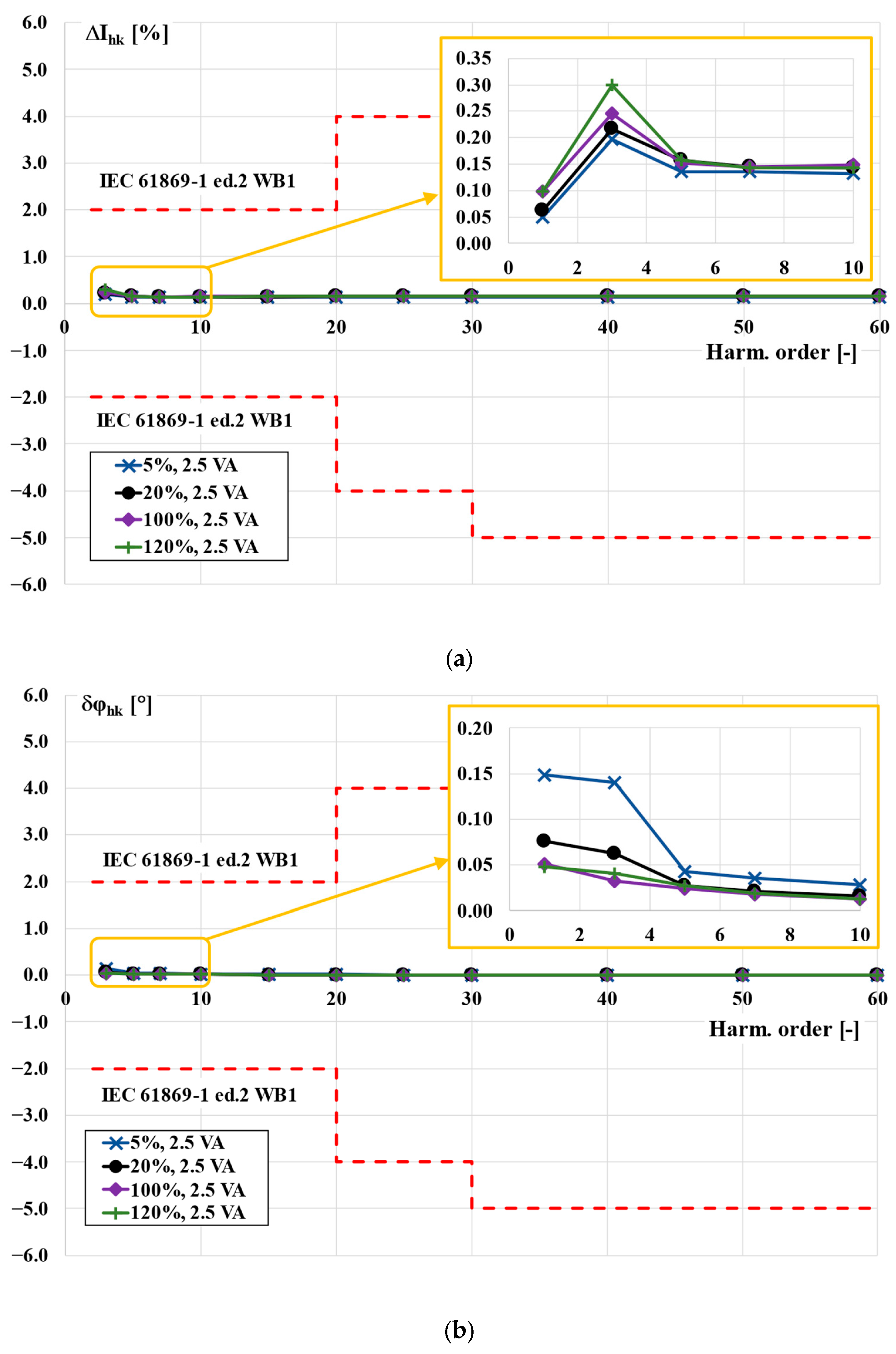
The values of the current error and phase displacement at harmonics for the transformation of a distorted primary current according to the TCT 300 A/5 A class 0.2 determined with the rated load are presented in Figure 4.
The TCT 300 A/5 A class 0.2 meets the requirements of the standard IEC 61869-1 for the optional accuracy class WB1 [17]. In this case, the level of the self-generated higher harmonics was reduced compared with the previous tested inductive CT. This was due to the decreased load apparent power.
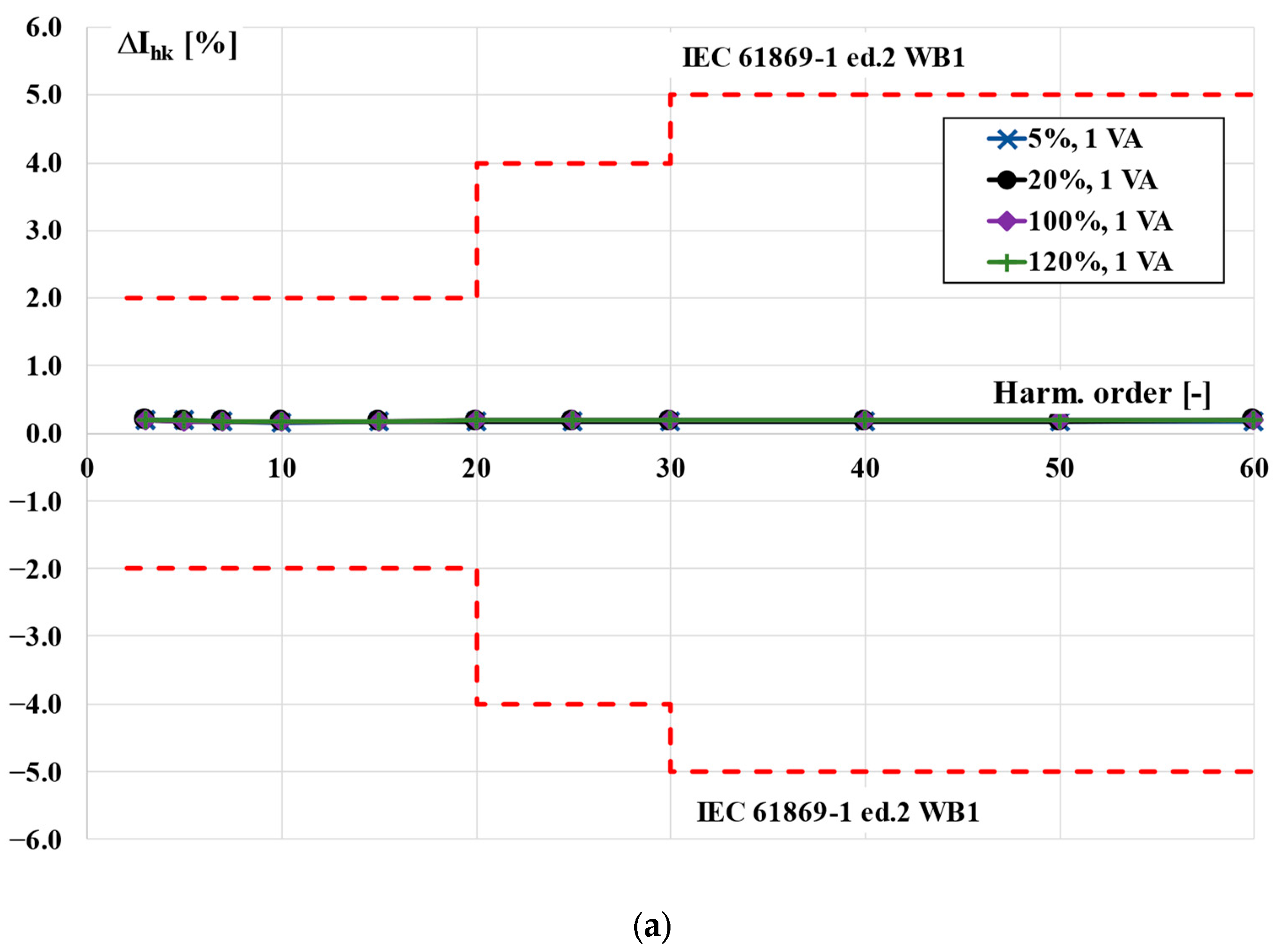
The values of the current error and phase displacement for the transformation of distorted primary current harmonics according to the tested inductive CT 300 A/5 A class 0.2 determined for the apparent power of a secondary winding load equal to 1 VA are presented in Figure 5.
Taking into consideration the results presented in Figure 5, the accuracy class of the tested inductive CT, in accordance with the standard IEC 612869 parts 1 and 2, was 0.2-WB1 [17,33].

4. Conclusions

The manufactured low-voltage inductive current transformers class 0.5 and 0.2 designed for a 50 Hz frequency sinusoidal current ensure a higher harmonics transformation accuracy up to and including a frequency equal to 3 kHz, in accordance with the optional wideband accuracy class WB1 defined by the second edition of the IEC standard 61869-1 published in 2023 [17]. The inductive load of the secondary winding causes a significant increase in the values of the current error and phase displacement with an increase in the frequency of the transformed higher harmonic. Therefore, the resistive load of the inductive current transformer secondary winding ensures higher wideband transformation accuracy of the distorted current. The compensation techniques proposed in scientific articles for improvement of the inductive current transformer performance over a wide frequency range are only necessary for poor-quality units strictly designed for a single rated operation frequency. Additionally, the application of these methods will always be associated with an increase in the complexity and cost of the final device due to the required implementation of additional electronic circuits. The appropriate solution is the proper design of the inductive current transformer, taking into consideration the use of modern magnetic materials for the magnetic core and its oversizing in relation to the requirements for a given accuracy class defined for the transformation of sinusoidal currents with a frequency of 50 Hz/60 Hz. The phenomenon of the self-distortion of the secondary current of the inductive current transformer resulting from the nonlinearity of its magnetic core’s magnetization characteristics should be taken into account in the design procedure. In the case of the tested inductive current transformers, the self-generated third, fifth and seventh secondary current harmonics had no significant impact on their wideband transformation accuracy. In the case of the tested low-voltage inductive current transformers, the requirements defined for the transformation of higher harmonics in the standard IEC 61869:2023 for the optional accuracy class WB1 were satisfied easily with a large margin to the limiting values of current error and phase displacement [17]. Therefore, these inductive current transformers ensure high transformation accuracy as demanded by the power quality monitoring and distorted electrical power and energy requirements.

Author Contributions

Conceptualization, E.S. and M.K.; methodology, E.S. and M.K.; validation, E.S. and M.K. formal analysis, E.S. and M.K.; investigation, E.S., P.K. and M.K.; resources, E.S. and M.K.; data curation, E.S., P.K. and M.K.; writing—original draft preparation, E.S. and M.K.; writing—review and editing, E.S. and M.K.; visualization, E.S.; supervision, M.K. All authors have read and agreed to the published version of the manuscript.

Funding

This research received no external funding.

Data Availability Statement

Not applicable.

Conflicts of Interest

The authors declare no conflict of interest.

References

  1. Hossain, E.; Tur, M.R.; Padmanaban, S.; Ay, S.; Khan, I. Analysis and Mitigation of Power Quality Issues in Distributed Generation Systems Using Custom Power Devices. IEEE Access 2018, 6, 16816–16833. [Google Scholar] [CrossRef]
  2. Liang, X. Emerging Power Quality Challenges Due to Integration of Renewable Energy Sources. IEEE Trans. Ind. Appl. 2017, 53, 855–866. [Google Scholar] [CrossRef]
  3. Montoya, F.G.; Baños, R.; Alcayde, A.; Montoya, M.G.; Manzano-Agugliaro, F. Power quality: Scientific collaboration networks and research trends. Energies 2018, 11, 2067. [Google Scholar] [CrossRef]
  4. Dirik, H.; Duran, I.U.; Gezegin, C. A Computation and Metering Method for Harmonic Emissions of Individual Consumers. IEEE Trans. Instrum. Meas. 2019, 68, 412–420. [Google Scholar] [CrossRef]
  5. Stano, E.; Kaczmarek, P.; Kaczmarek, M. Why Should We Test the Wideband Transformation Accuracy of Inductive Current Transformers? Energies 2022, 15, 5737. [Google Scholar] [CrossRef]
  6. Mingotti, A.; Peretto, L.; Tinarelli, R. Smart characterization of rogowski coils by using a synthetized signal. Sensors 2020, 20, 3359. [Google Scholar] [CrossRef]
  7. Mingotti, A.; Bartolomei, L.; Peretto, L.; Tinarelli, R. On the long-period accuracy behavior of inductive and low-power instrument transformers. Sensors 2020, 20, 5810. [Google Scholar] [CrossRef]
  8. Murray, R.; De Kock, J. Instrument transformers influence on harmonic measurements for grid code compliance. In Proceedings of the 2018 IEEE 4th Global Electromagnetic Compatibility Conference, GEMCCon, Stellenbosch, South Africa, 7–9 November 2018; IEEE: New York, NY, USA, 2019. [Google Scholar]
  9. Mingotti, A.; Peretto, L.; Bartolomei, L.; Cavaliere, D.; Tinarelli, R. Are inductive current transformers performance really affected by actual distorted network conditions? An experimental case study. Sensors 2020, 20, 927. [Google Scholar] [CrossRef]
  10. Kaczmarek, M.; Stano, E. Challenges of Accurate Measurement of Distorted Current and Voltage in the Power Grid by Conventional Instrument Transformers. Energies 2023, 16, 2648. [Google Scholar] [CrossRef]
  11. Kaczmarek, M.; Stano, E. New Approach to Evaluate the Transformation Accuracy of Inductive CTs for Distorted Current. Energies 2023, 16, 3026. [Google Scholar] [CrossRef]
  12. Cataliotti, A.; Cosentino, V.; Crotti, G.; Giordano, D.; Modarres, M.; Di Cara, D.; Tinè, G.; Gallo, D.; Landi, C.; Luiso, M. Metrological performances of voltage and current instrument transformers in harmonics measurements. In Proceedings of the I2MTC 2018—2018 IEEE International Instrumentation and Measurement Technology Conference: Discovering New Horizons in Instrumentation and Measurement, Houston, TX, USA, 14–17 May 2018; pp. 1–6. [Google Scholar]
  13. Fritsch, M.; Wolter, M. High-Frequency Current Transformer Design and Construction Guide. IEEE Trans. Instrum. Meas. 2022, 71, 1–9. [Google Scholar] [CrossRef]
  14. Letizia, P.S.; Crotti, G.; Mingotti, A.; Tinarelli, R.; Chen, Y.; Mohns, E.; Agazar, M.; Istrate, D.; Ayhan, B.; Çayci, H.; et al. Characterization of Instrument Transformers under Realistic Conditions: Impact of Single and Combined Influence Quantities on Their Wideband Behavior. Sensors 2023, 23, 7833. [Google Scholar] [CrossRef] [PubMed]
  15. Mateev, V.; Ralchev, M.; Marinova, I. Current Sensor Accuracy Enhancement by Harmonic Spectrum Analysis. In Proceedings of the 2019 13th International Conference on Sensing Technology (ICST), Sydney, Australia, 2–4 December 2019; pp. 1–4. [Google Scholar]
  16. Ranasingh, S.; Pradhan, T.; Dhenuvakonda, K.R. Calibration and frequency estimation in sensors for electrical parameter measurement using regression and metaheuristic based models. Expert Syst. 2023, 40, e13208. [Google Scholar] [CrossRef]
  17. IEC 61869-1; Inst. transf.—General Requirements. 2nd ed. IEC: Geneva, Switzerland, 2023.
  18. IEC 61869-6; Inst. transf.—Additional General Requirements for Low-Power Instrument Transformers. IEC: Geneva, Switzerland, 2016.
  19. Stano, E.; Kaczmarek, M. Analytical method to determine the values of current error and phase displacement of inductive current transformers during transformation of distorted currents higher harmonics. Measurement 2022, 200, 111664. [Google Scholar] [CrossRef]
  20. Kaczmarek, M.; Kaczmarek, P.; Stano, E. The Effect of the Load Power Factor of the Inductive CT’s Secondary Winding on Its Distorted Current’s Harmonics Transformation Accuracy. Energies 2022, 15, 6258. [Google Scholar] [CrossRef]
  21. Yan, P.; Liu, G.; Wang, R.; Xia, B.; Zhang, J.; Yi, L. development method and comparative analysis of measurement accuracy of new broadband and wide range current transformers. In Proceedings of the 2022 4th International Conference on Electrical Engineering and Control Technologies (CEECT), Shanghai, China, 16–18 December 2022; pp. 379–384. [Google Scholar]
  22. Kaczmarek, M.; Stano, E. Measuring system for testing the transformation accuracy of harmonics of distorted voltage by medium voltage instrument transformers. Measurement 2021, 181, 109628. [Google Scholar] [CrossRef]
  23. IEC 61869-2:2012/ISH1:2022 ED1; Interpretation Sheet 1—Instrument Transformers—Part 2: Additional Requirements for Current Transformers. IEC: Geneva, Switzerland, 2022.
  24. Crotti, G.; Chen, Y.; Çayci, H.; D’Avanzo, G.; Landi, C.; Letizia, P.S.; Luiso, M.; Mohns, E.; Muñoz, F.; Styblikova, R.; et al. How Instrument Transformers Influence Power Quality Measurements: A Proposal of Accuracy Verification Tests. Sensors 2022, 22, 5847. [Google Scholar] [CrossRef]
  25. Haas, A.; Niitsoo, J.; Taklaja, P.; Palu, I. analysis of electricity meters under distorted load conditions. In Proceedings of the PQ 2012: 8th International Conference—2012 Electric Power Quality and Supply Reliability, Tartu, Estonia, 11–13 June 2012; pp. 281–284. [Google Scholar]
  26. Zobaa, A.F.; Abdel Aleem, S.H.E. A new approach for harmonic distortion minimization in power systems supplying nonlinear loads. IEEE Trans. Ind. Inform. 2014, 10, 1401–1412. [Google Scholar] [CrossRef]
  27. Sharma, H.; Rylander, M.; Dorr, D. Grid impacts due to increased penetration of newer harmonic sources. IEEE Trans. Ind. Appl. 2016, 52, 99–104. [Google Scholar] [CrossRef]
  28. Mazin, H.E.; Xu, W.; Huang, B. Determining the harmonic impacts of multiple harmonic-producing loads. IEEE Trans. Power Deliv. 2011, 26, 1187–1195. [Google Scholar] [CrossRef]
  29. Cataliotti, A.; Di Cara, D.; Emanuel, A.E.; Nuccio, S. Current transformers effects on the measurement of harmonic active power in LV and MV networks. IEEE Trans. Power Deliv. 2011, 26, 360–368. [Google Scholar] [CrossRef]
  30. Vieira, D.; Shayani, R.A.; De Oliveira, M.A.G. Reactive Power Billing under Nonsinusoidal Conditions for Low-Voltage Systems. IEEE Trans. Instrum. Meas. 2017, 66, 2004–2011. [Google Scholar] [CrossRef]
  31. Lin, F.; Liang, B.; Shao, H.; Wang, H. Development of Wide-band Current Transformer for Precision Measurement of High-Current. In Proceedings of the 2020 Conference on Precision Electromagnetic Measurements (CPEM), Denver, CO, USA, 24–28 August 2020; pp. 20–21. [Google Scholar] [CrossRef]
  32. Takahashi, K.; Yamawaki, M.; Tadokoro, T. Current ratio transfer standard and improved equivalent ampere turn method. IEEE Trans. Instrum. Meas. 2013, 62, 1716–1722. [Google Scholar] [CrossRef]
  33. IEC 61869-2; Ins. Transf.—Additional Requirements for Current Transformers. IEC: Geneva, Switzerland, 2012.
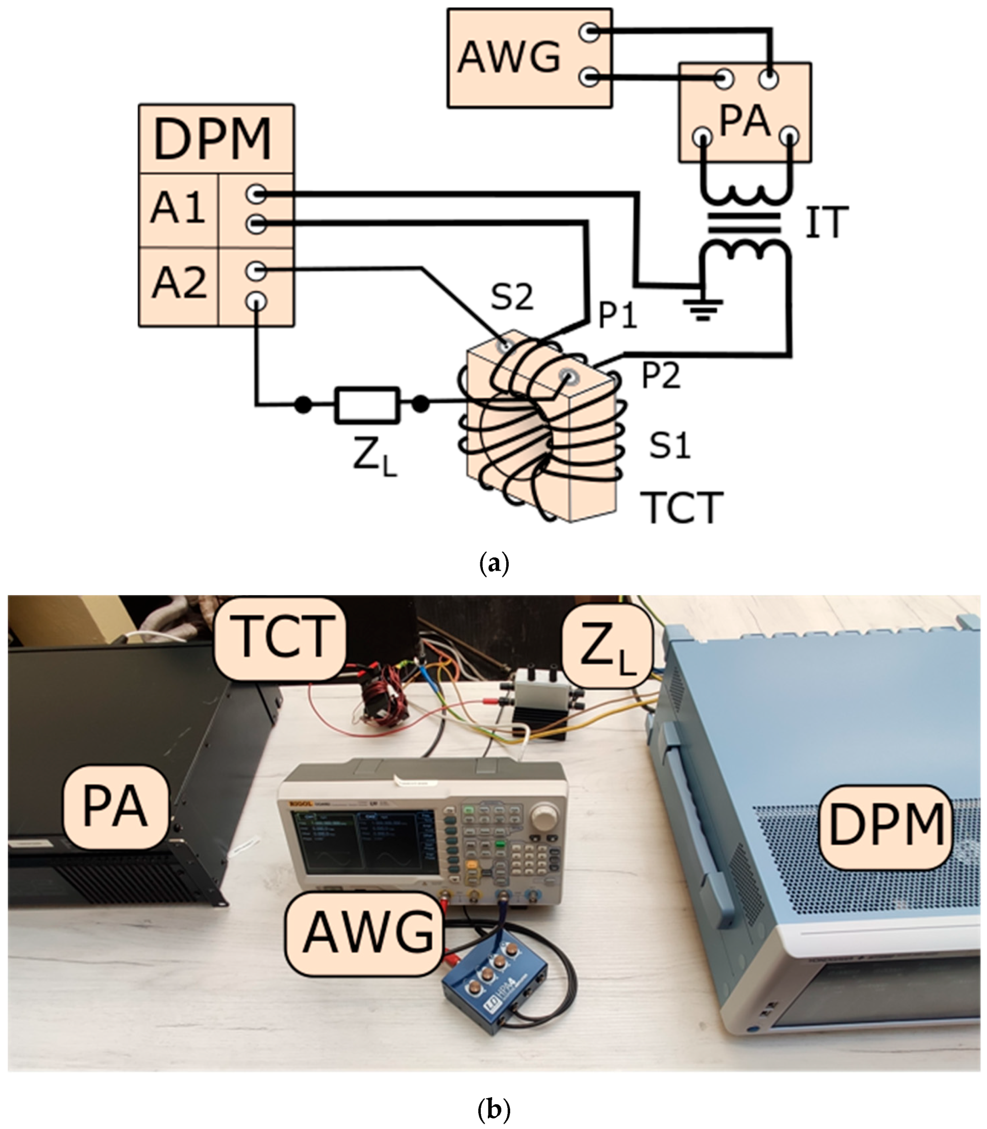
Figure 1. The measuring circuit used for the evaluation of the wideband transformation accuracy of the TCTs for distorted current harmonics: (a) block diagram, (b) photo. DPM—digital power meter, TCT—tested inductive current transformer, IT—insulation transformer, AWG—arbitrary waveform generator, PA—power amplifier, ZL—impedance of the load in the secondary winding of TCT, P1/P2—terminals of the additional primary winding, S1/S2—terminals of the secondary winding.
Energies 16 07206 g001
Figure 2. The transformation accuracy of harmonics according to the TCT 300 A/5 A class 0.5 with a rated load of the secondary winding being equal to 5 VA: (a) current error, (b) phase displacement.
Energies 16 07206 g002aEnergies 16 07206 g002b
Figure 3. The transformation accuracy of harmonics as determined using the TCT 300 A/5 A class 0.5 with 25% of the rated load of the secondary winding equal to 1.25 VA: (a) current error, (b) phase displacement.
Energies 16 07206 g003
Figure 4. The transformation accuracy of harmonics according to a TCT 300 A/5 A class 0.2 with a rated load of the secondary winding equal to 2.5 VA: (a) current error, (b) phase displacement.
Energies 16 07206 g004
Figure 5. The transformation accuracy of harmonics according to a TCT 300 A/5 A class 0.2 with a secondary winding load equal to 1 VA: (a) current error, (b) phase displacement.
Energies 16 07206 g005aEnergies 16 07206 g005b
Table 1. The values of the current error and phase displacement determined for transformation of 50 Hz sinusoidal current using the TCT 300 A/5 A class 0.5.
Percentage of the Rated CurrentLimitRated Load25% of Load
ΔI [%]δφ [°]ΔI [%]δφ [°]ΔI [%]δφ [°]
5±1.5±1.5−1.13−0.09−0.170.27
20±0.75±0.75−0.74−0.070.010.23
100±0.5±0.5−0.490.000.160.15
120±0.5±0.5−0.400.020.180.13
Table 2. The values of the current error and phase displacement for transformation of sinusoidal current with a 50 Hz frequency using the TCT 300 A/5 A class 0.2.
Percentage of the Rated CurrentLimitRated Load25% of Load
ΔI [%]δφ [°]ΔI [%]δφ [°]ΔI [%]δφ [°]
5±0.75±0.50.050.150.120.11
20±0.35±0.250.060.080.120.06
100±0.2±0.170.100.050.150.04
120±0.2±0.170.100.050.150.04
Disclaimer/Publisher’s Note: The statements, opinions and data contained in all publications are solely those of the individual author(s) and contributor(s) and not of MDPI and/or the editor(s). MDPI and/or the editor(s) disclaim responsibility for any injury to people or property resulting from any ideas, methods, instructions or products referred to in the content.