Abstract
To increase natural gas storage capacity and further utilize salt mine resources, salt cavern gas storage in the Yunying salt mine, Hubei Province, China, was simultaneously constructed in two different mining layers (K3 and K4). The purpose of this study was to investigate the long-term feasibility of operating salt caverns for gas storage in two mining layers. Based on the geological conditions and sonar test results, the geometric parameters for the salt caverns in the two mining layers were designed, and a 3D geomechanical model was built to predict the cavern stability. The corresponding evaluation index included the displacement, volume shrinkage rate, equivalent strain, and dilatancy factor. The results show that simultaneously operating salt cavern gas storage in two mining layers is feasible, and the operational pressures for the salt caverns in mining layers K3 and K4 should be no less than 4–9 and 7–12 MPa, respectively, to satisfy the stability requirements. The surrounding rock of the salt caverns presents a larger displacement and volume reduction compared with cases in which the salt caverns are operated in a single mining layer. Increasing the injection–withdrawal frequency increases the deformation of the surrounding rock.
1. Introduction
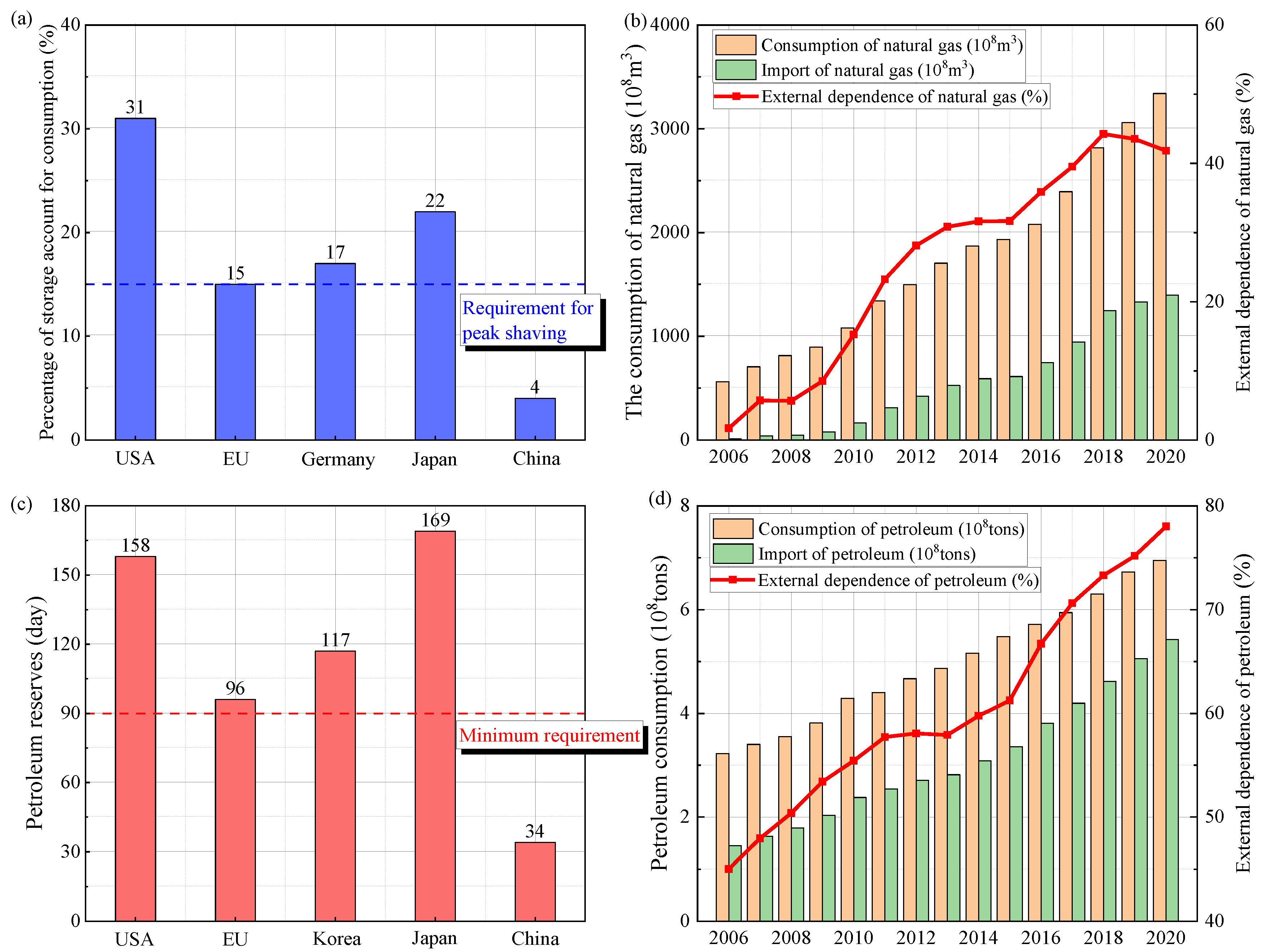
Energy is an important material foundation for human survival, civilization, and progress and is also the lifeblood of the economic development of a country. During the past 40 years of reform and opening up in China, marked changes have occurred in the lives of its citizens, and its economy has rapidly developed. In the meantime, the consumption of natural gas and oil per year in China has been increasing in recent years, from 56 billion cubic meters and 322 million tons in 2006 to 3340 billion cubic meters and 695 million tons in 2020, respectively (Figure 1b,d). However, the storage capacity for natural gas and oil in China is quite low, only accounting for 4% of the natural gas consumption and containing 34 days of oil consumption (Figure 1a,c). Because large-scale natural gas and oil storage is critical for peak shaving and energy safety, building large-scale underground oil and natural gas reserves is essential [1].
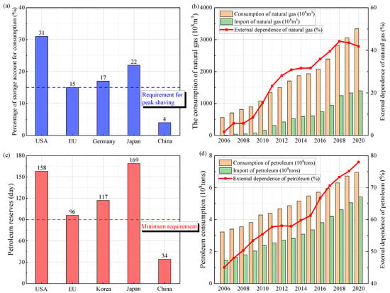
Figure 1.
China’s annual oil and gas consumption and reserves from 2006 to 2020.
Because rock salt is characterized by favorable rheology [2,3], low permeability [4,5], and self-recovery after damage [6], underground salt caverns are the optimal medium for the storage of hydrocarbons, including natural gas [7], oil, compressed air [8], hydrogen [9,10,11], and radioactive waste [12]. Compared with other reserve types for natural gas, including aquifers and depleted reservoirs, salt cavern gas storage is safer and has a higher percentage of cushion gas and a more flexible injection mode. Unlike the salt domes in Germany and the USA, the rock salt formation in China is characterized by a bedded structure. The first underground gas storage system using salt caverns, the Jintan salt district in Jiangsu Province, was operated in China in 2007. In recent years, an increasing number of salt mines in China have undergone feasibility analyses for constructing salt cavern gas storage systems, including Yunying in Hubei Province, Huai’an in Jiangsu Province [13], Qianjiang in Hubei Province [14], and Ningjin in Hebei Province [7]. Because the gas pressure is lower than the in situ stress at the corresponding depth, the surrounding rock of the salt cavern undergoes continuous creep deformation within its service life. Thus, investigating the cavern safety and stability deserves more attention.
Extensive studies have been conducted on the stability of salt caverns used for gas storage. Deng, et al. [15] employed the strength reduction finite-element method and deformation reinforcement theory, and analyzed the local fracture position and failure mode of gas storage cavities. The simulation results were also compared with the geomechanical model test results, and the results were consistent with each other. Shahmorad, et al. [16] used the Burger analytical, power law, and Waste Isolation Pilot Plant empirical models to calculate the behaviors of caverns in a salt structure. The volume shrinkage, dilation safety factor, and operational pressures were studied, and the authors concluded that using the Cpower model induces a more conservative result for cavern stability. Because the gas pressure inside the salt cavern varies owing to periodic injection–withdrawal, researchers have analyzed the mechanical properties of salt caverns under cyclic loading. Habibi, et al. [17] conducted a stability study of the Nasrabad salt cavern under coupled time-dependent thermomechanical loading. Khaledi, et al. [18] used an elastic-viscoplastic-creep model to predict the long-term response of solution-mined caverns in all life phases, including leaching, debrining, and cyclic loading. Volume variation, damage evolution, and permeability changes were investigated.
Table 1 lists the stability studies conducted on underground salt caverns in China. The cavern shapes included pear-shaped, horizontal, hemisphere–cylinder–cone, small-spacing two-well, two-well-horizontal saddle-shaped, ellipsoid, and large-spacing two-well (Figure 2). In terms of actual engineering, sonar test results were directly used for modeling to evaluate the cavern stability. The cavern depths ranged from 600 to 2900 m, and the corresponding operational pressure varied from 3 to 36 MPa. Research on the stability of caverns used for natural gas storage usually involves the determination of the cavern geometry parameters, pillar width, operational pressures, roof stability, leakage for the interlayer, height of casing shoes, creep constitutive model, and economic analysis. The stability analysis includes laboratory tests aimed at obtaining the mechanical parameters of rocks, cavern design of geometric parameters, and numerical simulations for predicting the long-term behavior of salt caverns.
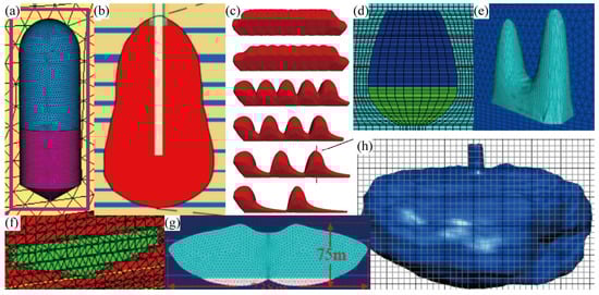
Figure 2.
Caverns in the literature review listed in Table 1. (a) Hemisphere–cylinder–cone. (b,d) Pear. (c,f) Horizontal. (e) Two-well-horizontal saddle-shaped. (g) Small-spacing two-well. (h) Sonar results.
Rock salt strata in China can be characterized as thin, interlayered, bedded, and highly impure. The height of a cavern depends largely on the thickness of the salt formation, and is much smaller than that in thick domes and thick layers of rock salt deposits in Europe and the USA. Hence, the diameter of the bedded salt cavity must be greater than its height to obtain a larger volume for gas storage. Xing, et al. [19] analyzed the stability of horizontal cavities with various diameters and minimal gas pressures over the long term, and concluded that a horizontal cavern is more efficient, profitable, and suitable, especially in Chinese geological behavior. Regarding the construction of a horizontal cavern, Liu et al. conducted physical simulation tests on large molded salt samples and investigated the variables affecting the cavity outline. They also performed construction modeling and shape prediction based on a flow and concentration field model that considered the accumulated insoluble substances. The simulation results were verified using field data from a cavern in Huai’an, China. Because the roof is a key position for the stability of a horizontal salt cavern, Zhang, et al. [20] analyzed the failure mechanism and stability of a bedded roof based on theoretical calculation and numerical simulation. They concluded that the most important influencing factors included the length of the long side, the thickness of the protective salt layer, and internal pressure. Wang, et al. [21] theoretically analyzed the surface settlement of a horizontal salt cavern used for storing natural gas using the conformal mapping method in a complex variable function, which considers the superposition and viscoelastic correspondence principle. This surface settlement model was further verified using numerical simulation results. Because new wells usually must be drilled for the reconstruction of old horizontal caverns, Zhang, et al. [22] investigated the effects of newly drilled wells on cavern stability.

Table 1.
Literature review of the stability analysis of underground salt caverns used for gas storage in China.
Table 1.
Literature review of the stability analysis of underground salt caverns used for gas storage in China.
| Year | Location | Cavern Shape | Cavern Depth (m) | Operation Pressures (MPa) | Research Focus | Academic (A)/ Engineering (E) | References |
|---|---|---|---|---|---|---|---|
| 2014 | / | Pear | 1200–1500 | 6–15 | Dynamic response under seismic loads | A | [23] |
| 2016 | Jintan, Jiangsu Province | Pear | 858–1030 | 6–17 | Salt cavern gas storage close to an old cavern | E | [24] |
| 2016 | Yunying salt district, Hubei Province | Horizontal | 640–680 | 3–9 | Horizontal caverns in bedded salt structure | E | [25] |
| 2018 | Jianghan salt district, Hubei Province | Hemisphere–cylinder–cone | 2000 | 17–34 | Optimization of the shape, dimensions, operating parameters, and pillar width | E | [14] |
| 2018 | Jintan, Jiangsu Province | Sonar results | 1000 | 7–15.8 | Roof collapse investigation | E | [26] |
| 2020 | / | Horizontal | 1000 | 16 | Stability of the bedded key roof | A | [20] |
| 2020 | / | Small-spacing two-well | 1000 | 12 | Effect of ratio of long axis to short axis | A | [27] |
| 2021 | / | Two-well-horizontal saddle-shaped | 1250–1500 | 16–23 | Determination of the height of casing shoes | A | [28] |
| 2022 | / | Two-well-vertical | 1030–1150 | 7–21 | Different roof shapes and injection–production frequency | A | [29] |
| 2022 | / | Ellipsoid | 600 | 4.5–11.5 | Nonlinear creep model including damage and hardening | A | [30] |
| 2022 | / | Large-spacing two-well | 1130 | 7–21 | Indoor physical simulation experiments Internal pressure optimization | A | [31] |
| 2022 | Sanshui Basin, Guangdong Province | Pear | 1400 | 10–23 | Volume convergence, plastic zone distribution, pillar width, displacement | E | [32] |
| 2022 | Ningjin, Hebei Province | Hemisphere–cylinder–cone | 2700–2900 | 28–36 | Extremely deep salt formation | E | [7] |
| 2022 | Pingdingshan, Henan Province | Pear | 1600 | 13–27 | Creep-damage constitutive model Effect of gas extraction rates | E | [33] |
| 2023 | / | Horizontal | 1050 | 7.21–19.2 | Multistep horizontal salt caverns Economic analysis | A | [34] |
To increase the storage capacity of natural gas and further utilize salt mine resources, a salt cavern gas storage in the Yunying salt mine, Hubei Province, China, was simultaneously constructed in two different mining layers. In this study, the feasibility of this utilization pattern was analyzed. The cavern shape and geometric parameters in the different mining layers were designed based on a sonar survey. A 3D geotechnical model was built according to the strata distribution. The stabilities of the underground salt caverns in the two mining layers were assessed under different operating pressures based on a comprehensive evaluation index, including displacement, volume shrinkage rate, equivalent strain, and dilatancy factor. The effects of the cyclic period and caverns in the adjacent mining layers on the cavern stability were also investigated. This study provides a foundation for the construction of salt cavern gas storage systems in the Yunying salt district, Hubei Province, China, and enriches the design of underground salt caverns for hydrocarbon storage, particularly in bedded salt formations.
2. Methodology
This study aims to assess the feasibility of simultaneously constructing salt cavern gas storage in two different mining layers. The research approach for evaluating cavern stability involves numerical simulation. Therefore, in this section, we analyze the geological conditions in the Yunying salt district, and design the cavern shape based on sonar test results. Subsequently, we establish a numerical model considering strata distribution and cavern geometry parameters. We describe the operational mode, mechanical parameters, and constitutive relationship of the surrounding rock to provide the foundation for the numerical simulation. Finally, we calculate the long-term mechanical responses of the salt cavern under varying operational pressures, and assess cavern stability based on predetermined criteria.
2.1. Geological Conditions in Yunying Salt Mine
The Yunying salt mine is located in the northeast of the Jianghan Basin, Hubei Province, China (Figure 3). The salt layer and interlayer exhibit an interbedded structure of varying thickness, with some salt groups forming densely interbedded structures. A contact layer surface is present between these layers, indicating a layered sedimentary environment. The geological properties of the Yunying salt mine can be summarized as follows:
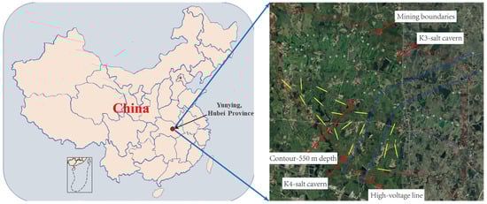
Figure 3.
Well location deployment diagram of the salt caverns in Yunying salt district.
The salt layer is shallow, with the top boundary of the 06 salt group at a burial depth of 200–700 m in a specific engineering area. The area with a burial depth greater than 500 m covers 13.3 km2, while the area with a burial depth greater than 600 m spans 5.7 km2.
The salt group is uniformly distributed and primarily layered. The thicknesses of the central two zones are significant, exceeding 240 m, and the structure of the salt rock ore layer is straightforward. The average NaCl grade generally falls within the range of 60–80%, with associated Na2SO4 content (soluble) ranging from 5 to 30%.
The sandwich lithology typically consists of argillaceous hard paste rock, hard paste mudstone, and argillaceous calcium glauconite, with thicknesses mostly less than 1 m. The primary chemical components include Na2SO4 (ranging from 0.06–30.41%), CaSO4, and NaCl (ranging from 3.89 to 30.93%).
2.2. Design of Salt Caverns
Figure 3 shows the locations of the Yunying salt district and the mining boundaries. According to the strata distribution (Figure 4), the depths of the K3 and K4 mining layers are approximately 470–590 and 688–714 m, respectively. Based on sonar test results of an abandoned cavern, the diameter of the cavern in the K3 mining layer is approximately 70 m. The cavern bottom is 590 m deep, and the depth of the cavern roof is approximately 520 m. The distance between two wells for a horizontal cavern is approximately 400 m. The horizontal section is assumed to be a cylinder, and the height is estimated to be 50 m according to the mass of the mined salt and the percentage of an insoluble salt in the Yunying salt mine (Figure 5c). The salt cavern in the K4 mining layer is designed in the shape of a tunnel, the length and height of which are 300 and 25.81 m, respectively (Figure 5d). According to Figure 4, there is an insoluble interlayer with a thickness of 30.76 m that prevents the connection of mining layers K3 and K4. This assumption is based on actual salt-mining experience and was verified using sonar test results. Thus, to utilize the salt mine resources further and increase the storage capacity for natural gas, the caverns used for gas storage in mining layers K3 and K4 were simultaneously constructed.
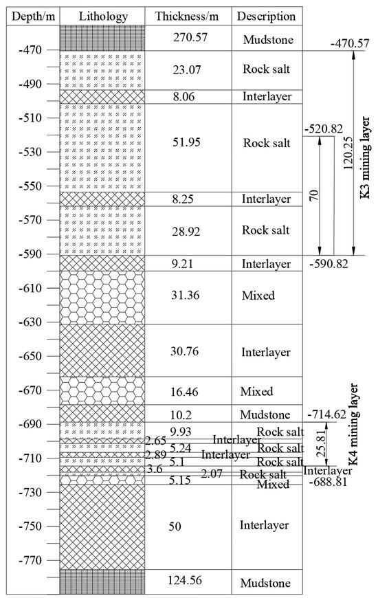
Figure 4.
Formation distribution and location of Well 1071: the “mixed” layer includes glauberite, anhydrite, mudstone, and rock salt.
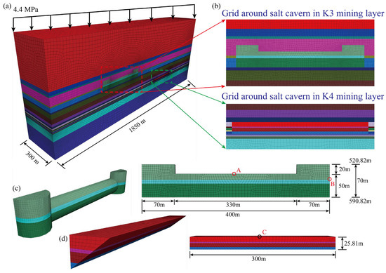
Figure 5.
(a) Three-dimensional geotechnical model of the horizontal salt cavern in Yunying salt district, (b) grid around salt cavern in K3 and K4 mining layers, and (c,d) cavern shape and dimensions of the salt cavern in K3 and K4 mining layers.
2.3. Simplifications of Numerical Simulation
The gas pressure cycling within a salt cavern storage facility gives rise to several thermodynamic issues. Within the storage facility, changes in gas pressure result in periodic fluctuations in temperature. The temperature fluctuations inside the storage facility create temperature gradients, where different locations experience varying temperatures. Temperature variations lead to heat conduction, altering the temperature distribution within the surrounding rock. Variations in gas temperature can impact its physical properties, affecting gas flow and storage behavior. Temperature gradients and thermal stresses may affect the stability of the cavern walls. Temperature fluctuations and thermal conduction effects can alter geological conditions in the vicinity of the salt cavern, including hydrogeological and groundwater flow patterns.
Based on previous studies about cavern stability evaluation [8,33,35], two simplifications were conducted. As the gas velocity is quite low (about 4.2 × 10⁻¹⁰ L/s), we disregarded the impact of gas compression and expansion on the cavern’s temperature, and employed ideal gas models, omitting the non-ideal properties of the gas. These simplification measures reduce the computational complexity of numerical simulations, focusing primarily on the impact of gas pressure variations on cavern stability. The practicality and reliability of the simplifications have been widely used and validated by many scholars [16,34,36,37].
2.4. Numerical Simulation Model
The geological structure and sonar test results provide a reference for establishing a numerical simulation model [8]. Rhino software 7.4 [38] was used to build a 3D geomechanical model, and the Griddle plug-in was used to subdivide the grids to a more refined degree [39]. Considering the symmetry of the model, a half model was built to improve the calculation efficiency (Figure 5a). The upper surface of the numerical model is free, and the four vertical surfaces and the bottom are constrained for normal displacement. The dimensions of the cuboid simulation model in the three directions are 1850, 300, and 500 m. The self-weight of the overlying strata is calculated as a distribution load by multiplying the depth and average density of the strata. It is 4.4 MPa at the top of the simulation model [40]. The in situ stress gradient is considered to be 2.2 MPa/100 m. The grids extracted from the geomechanical model are imported into the FLAC3D 6.0 software [41], which is widely used to solve the large-strain issue of geotechnical materials. Because the zone around the salt cavern is the most important area for stability analysis, the elements close to the salt cavity are small, and the element size increases with increasing distance from the cavern (Figure 5b). This distribution also increases the calculation efficiency. The numbers of nodes and elements are 182,147 and 816,505, respectively. The shapes of the elements are hexahedra, prisms, pyramids, and tetrahedra, the percentages of which are 85.71%, 1.95%, 9.34%, and 3.00%, respectively.
2.5. Input of Stability Analysis
The Norton Power law is used to describe the creep response of the surrounding rock of salt caverns during operation [42]. Because the transient creep of the surrounding rock is relatively short and the accelerated creep stage is avoided, this constitutive relationship is widely used in the stability analysis of underground caverns [7]. The creep formula is
where is the axial strain rate in the steady deformation state, and and are the maximum and minimum principal stresses, respectively. The mechanical parameters of the rock cores in the Yunying salt district are based on tests conducted by Yang, Wang, Qu, Ma, Li, Shi and Daemen [25] (Table 2).
Table 2.
Mechanical parameters for the rock cores in Yunying salt district.
The operation modes of natural gas storage include injection, high-pressure, withdrawal, and low-pressure stages. The cyclic period of the gas pressure inside a salt cavern is usually one year, and each stage lasts for three months [43]. The maximum operational gas pressure is associated with the depth of the salt cavern and is approximately 75–80% of the minimum principal stress at the depth of the casing shoe. Thus, the maximum operational pressures in the K3 and K4 mining layers were set to 9 and 12 MPa, respectively. The minimum operational pressures in mining layers K3 and K4 were set to 4 and 6 MPa, respectively, based on engineering experience [7,25].
3. Results
3.1. Stability Evaluation under Various Operating Pressures
At the given depth, the gas pressure is lower than the in situ stress, resulting in creep deformation of the surrounding rock in the salt cavern due to deviated stress. Variations in pressure lead to changes in the deviated stress of the surrounding rock, thereby enabling the acquisition of mechanical responses of the salt cavern based on the constitutive relationship. Based on a previous study on the stability analysis of gas storage salt caverns in China [7], the displacement, volume shrinkage rate, equivalent strain, and dilatancy factor were selected as the evaluation criteria. These evaluation factors are based on the safety, stability, and utility of salt caverns, and comprehensively reflect the deformation behavior of rock salt, including large strain, plasticity, and dilatancy [44]. The operating pressures in the two mining layers correspond to four modes: (1) 4–9 MPa in the K3 salt cavern and 6–12 MPa in the K4 salt cavern, (2) 4–9 MPa in the K3 salt cavern and 7–12 MPa in the K4 salt cavern, (3) 5–9 MPa in the K3 salt cavern and 6–12 MPa in the K4 salt cavern, and (4) 5–9 MPa in the K3 salt cavern and 7–12 MPa in the K4 salt cavern. The gas velocity during the injection–withdrawal stages is approximately 4.2 × 10⁻¹⁰ L/s. In this section, the cavern behavior in the above four operational modes is described first. Then, the effects of the adjacent mining layer and cyclic period on the stability of the salt cavern are analyzed.
3.1.1. Displacement
Figure 6 shows the displacement contours of the surrounding rock under various operational gas pressures after 30 years of service. The displacement denotes the vector sum in three mutually perpendicular directions. The displacement of the rock around the cavity is the largest, and the displacement is smaller in the area farther from the cavity. For the salt cavern in the K3 mining layer, the maximum displacement points are in the middle and lower parts of the side of the cavity. Owing to the shape of the flat top of the salt cavern in the K4 mining layer, the middle area at the top of the cavity has the maximum displacement. The maximum displacements of the surrounding rock under the four different operational pressures are 3.729, 3.488, 3.619, and 2.825 m. This implies that, with increasing operational pressure in the salt cavern of the K3 mining layer, the maximum displacement gradually decreases under the same gas pressure in the salt cavern of the K4 mining layer. The same conclusion is obtained when only the operational pressure in the salt cavern of the K4 mining layer is increased under the same gas pressure in the salt cavern of the K3 mining layer.
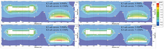
Figure 6.
Displacement contours of the surrounding rock of the cavern under different operation pressures after 30 years of operation. (a) K3 4–9 MPa, K4 6–12 MPa. (b) K3 4–9 MPa, K4 7–12 MPa. (c) K3 5–9 MPa, K4 6–12 MPa. (d) K3 5–9 MPa, K4 7–12 MPa.
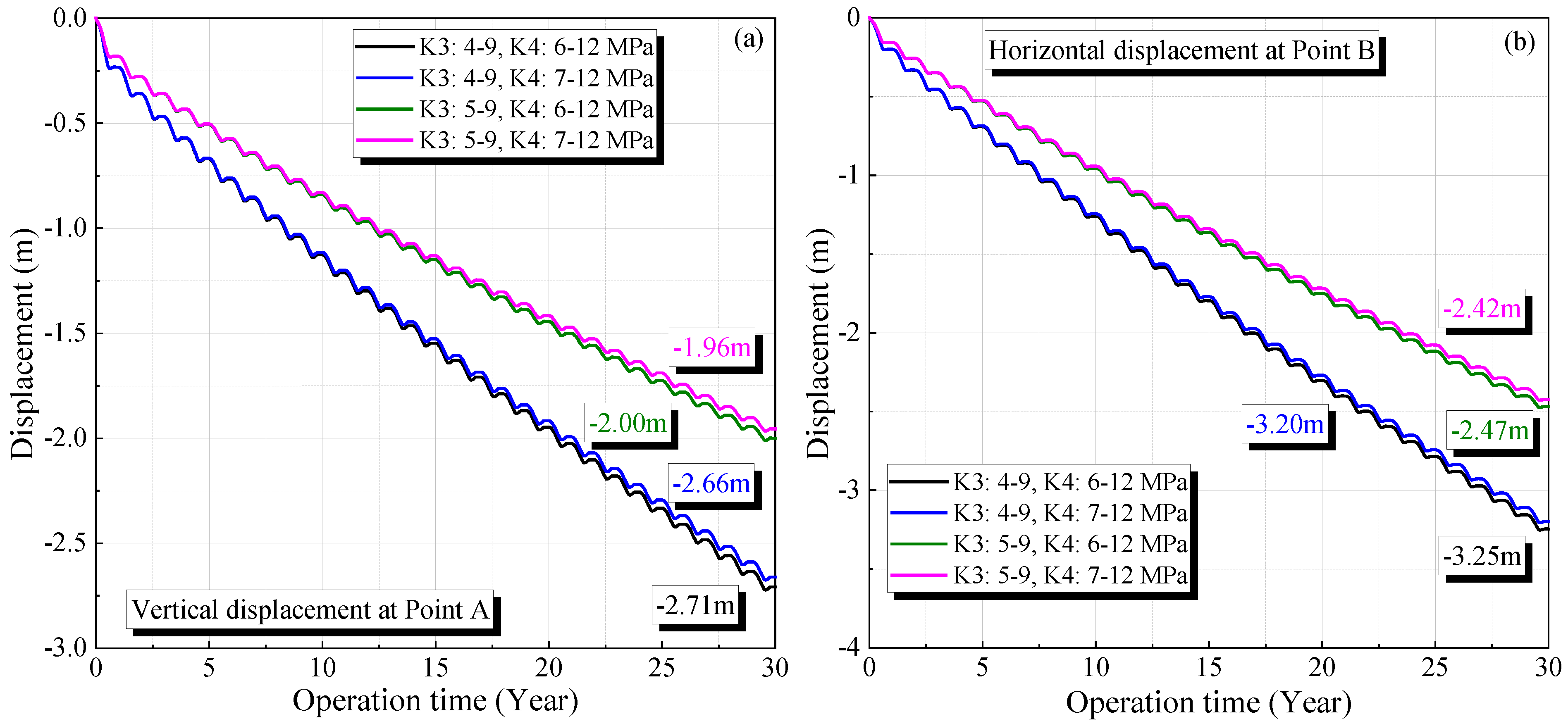
Figure 7 shows the displacement variation at the maximum deformation points during the 30-year operation period (Points A and B are shown in Figure 5). The displacement increases with operation time, which grows rapidly in the initial stage. Corresponding to the periodic change in the operational gas pressure, the displacement exhibits a regular fluctuation. After 30 years of operation, the displacements under four different operational pressures are 2.71, 2.66, 2.00, and 1.96 m at Point A, and 3.25, 3.20, 2.47, and 2.42 m at Point B, respectively.
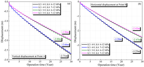
Figure 7.
Variation of the vertical displacement of the surrounding rock of the cavern in K3 (a) and K4 (b) under different operation pressures during 30 years of operation.
3.1.2. Volume Shrinkage Rate
The surrounding rock experiences continuous deformation during operation because the gas pressure inside the salt cavern is lower than the in situ stress at the corresponding depth. This induces a volume reduction in the salt cavern, which influences the cavern stability and decreases its storage capacity [14]. The ratio between the reduced and the original volume is defined as the volume shrinkage rate.
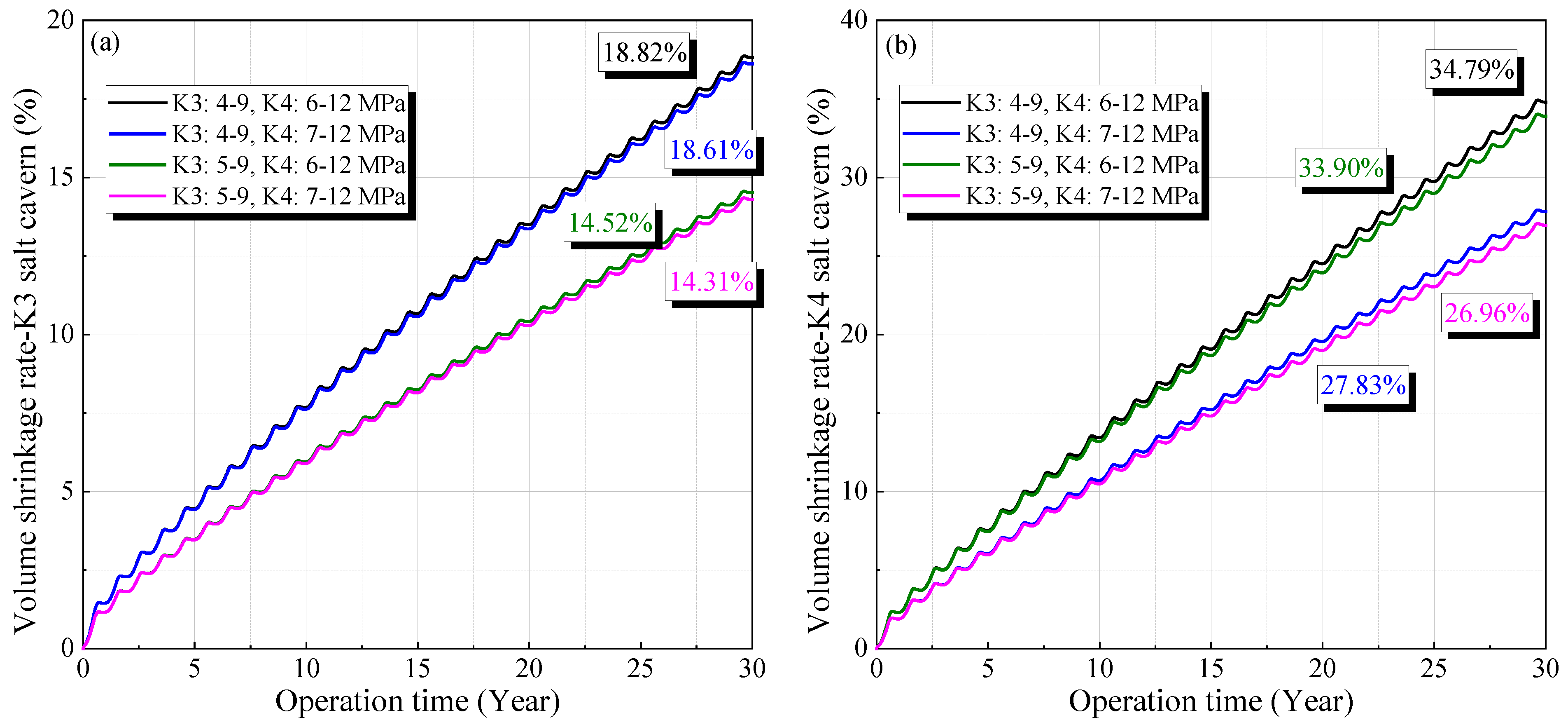
Figure 8 shows the variation in the volume shrinkage rate under different gas pressures, which decreases with increasing operational pressure and gradually increases with operation time. The cavern volume decreases rapidly in the initial stage, and the reduction rate gradually stabilizes. After 30 years of operation, the volume reduction rates under different gas pressures are 18.82%, 18.61%, 14.52%, and 14.31% for the salt cavern in the K3 mining layer, and 34.79%, 33.91%, 27.83%, and 26.96% for the salt cavern in the K4 mining layer, respectively. This indicates that the salt cavity in the K4 mining layer undergoes a larger volume reduction. To ensure the availability and safety of the salt cavern, its volume reduction rate after 30 years of operation should be lower than 30% [7,45]. Hence, considering the oversized volume reduction shown in Figure 8b, the minimum operating pressure inside the salt cavern in the K4 mining layer should be no less than 7 MPa.
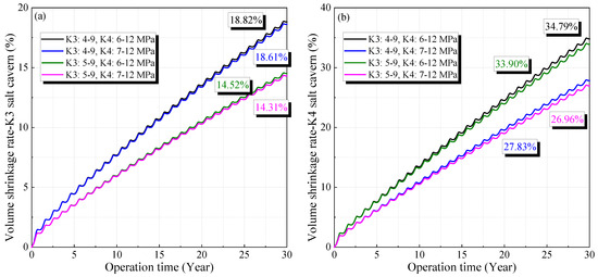
Figure 8.
Variation of the volume shrinkage rate of the cavern in K3 (a) and K4 (b) under different operation pressures during 30 years of operation.
3.1.3. Equivalent Strain
Considering the ductility of rock salt and the conditions of the three-dimensional stress field for the surrounding rock, the equivalent strain is used to describe the rock deformation. The mathematical formula [46] is
where is the equivalent strain, and , , and are the maximum, intermediate, and minimum principal strains, respectively. The variation in equivalent strain during one injection–withdrawal of gas should be less than 3% to avoid creep failure [44]. The variation period of the gas pressure is one year during the 30-year service time. Thus, the cumulative equivalent strain should be no more than 0.9 after operation. As shown in Figure 9, the maximum values of the equivalent strain after a 30-year operation under different gas pressures are 0.191, 0.155, 0.186, and 0.151. This means that the four operating pressures meet the cavern stability requirements from the perspective of equivalent strain. The surrounding rock close to the cavern wall is characterized by a larger equivalent strain. The farther from the cavity, the lower the strain of the surrounding rock.
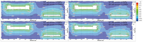
Figure 9.
Equivalent strain contours of the surrounding rock of the cavern under different operation pressures after 30 years of operation. (a) K3 4–9 MPa, K4 6–12 MPa. (b) K3 4–9 MPa, K4 7–12 MPa. (c) K3 5–9 MPa, K4 6–12 MPa. (d) K3 5–9 MPa, K4 7–12 MPa.
3.1.4. Dilatancy Factor
With increasing deformation, the rock salt experiences microcrack propagation, and the volume increases. This process induces an increase in permeability and strength degradation, which is defined as dilatancy [46]. For the dilatancy criterion of rocks, there is a linear relationship between the first invariant of stress and the second invariant of deviatoric stress [47]. The dilatancy factor for rocks in the Yunying salt district, China, is determined according to a previous study [8]:
Here, DF is the dilatancy factor, and a and b are material parameters. The compression criterion and dilatancy criterion are calculated as
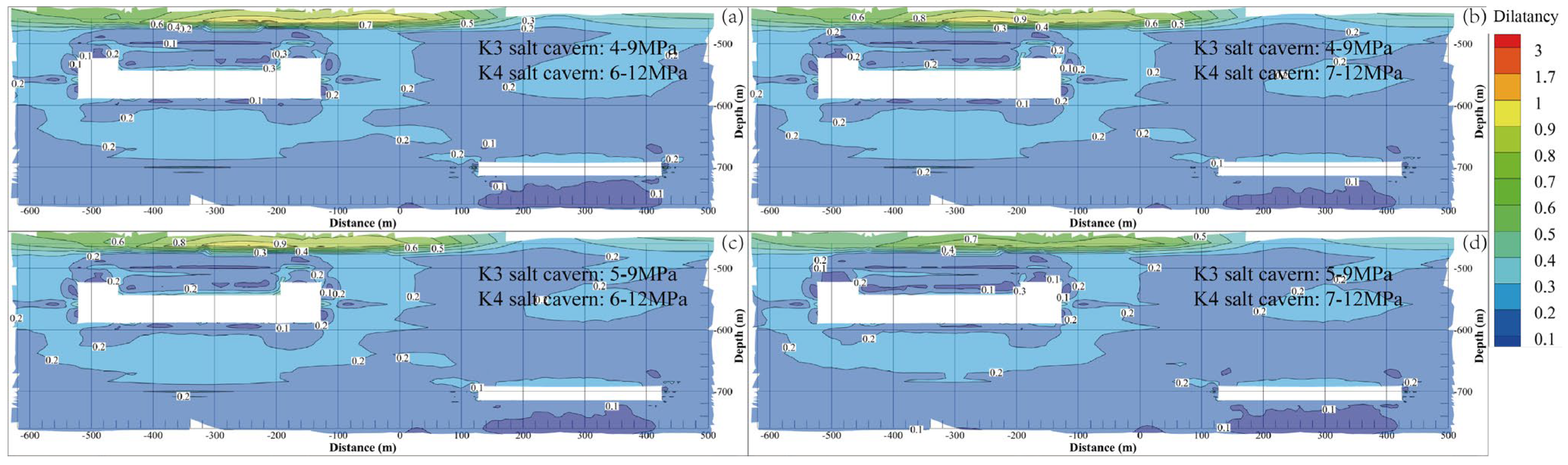
Thus, to avoid the dilatancy of the surrounding rock during operation, the dilatancy factor should not exceed one. Figure 10 shows the dilatancy factor contours of the surrounding rock after 30 years of operation under different gas pressures. The rock surrounding the cavern wall has a larger dilatancy factor, and its value generally decreases with increasing distance from the cavern. Because the salt and interlayer have different mechanical parameters, the interlayer zone on top of the salt cavern in the K3 mining layer is characterized by the largest dilatancy factor. The maximum values of the dilatancy factor under the four gas pressures are 4.864, 4.263, 4.054, and 3.575. This indicates that the aforementioned operational pressures satisfy the stability requirements from the perspective of the dilatancy factor.
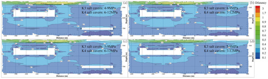
Figure 10.
Dilatancy factor contours of the surrounding rock of the cavern under different operation pressures after 30 years of operation. (a) K3 4–9 MPa, K4 6–12 MPa. (b) K3 4–9 MPa, K4 7–12 MPa. (c) K3 5–9 MPa, K4 6–12 MPa. (d) K3 5–9 MPa, K4 7–12 MPa.
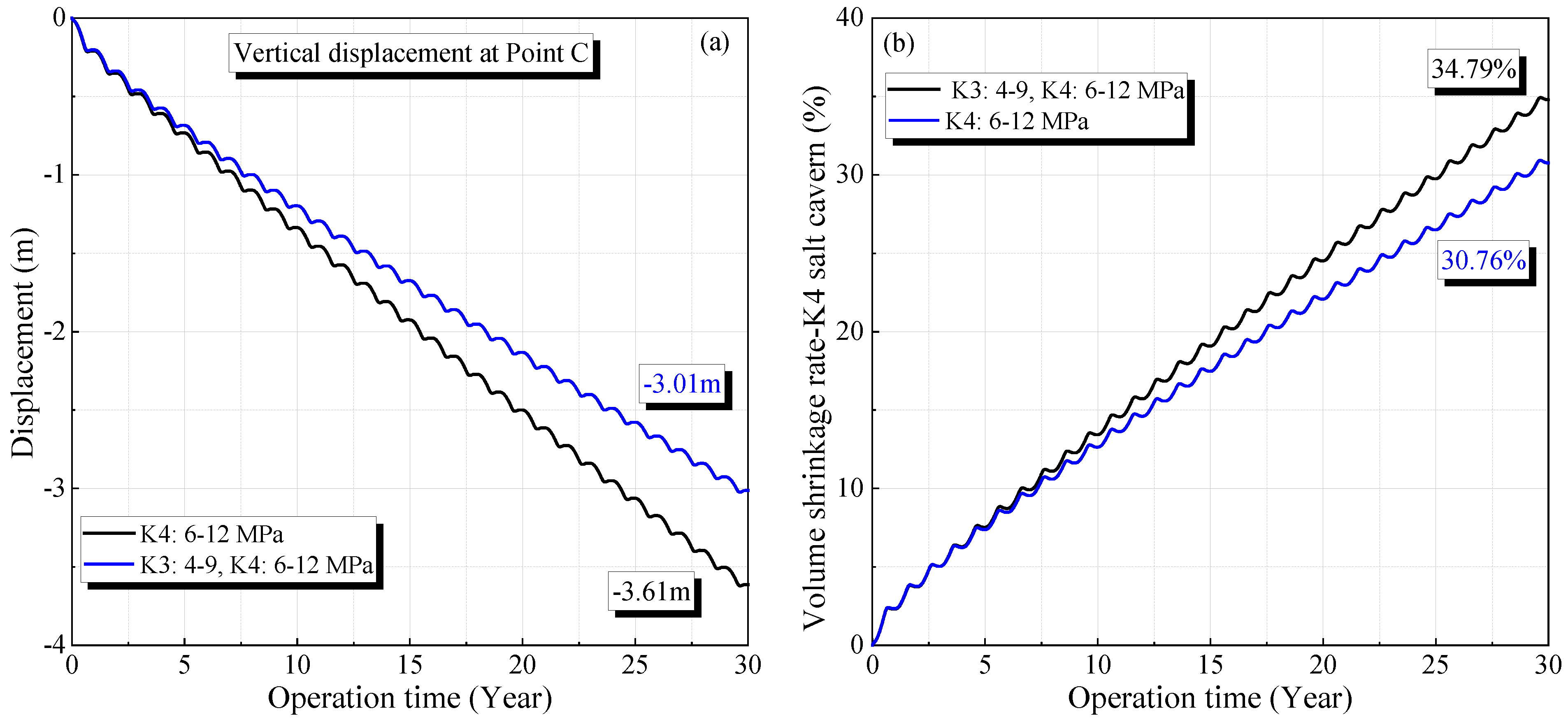
3.2. Effects of Caverns in Adjacent Mining Layers
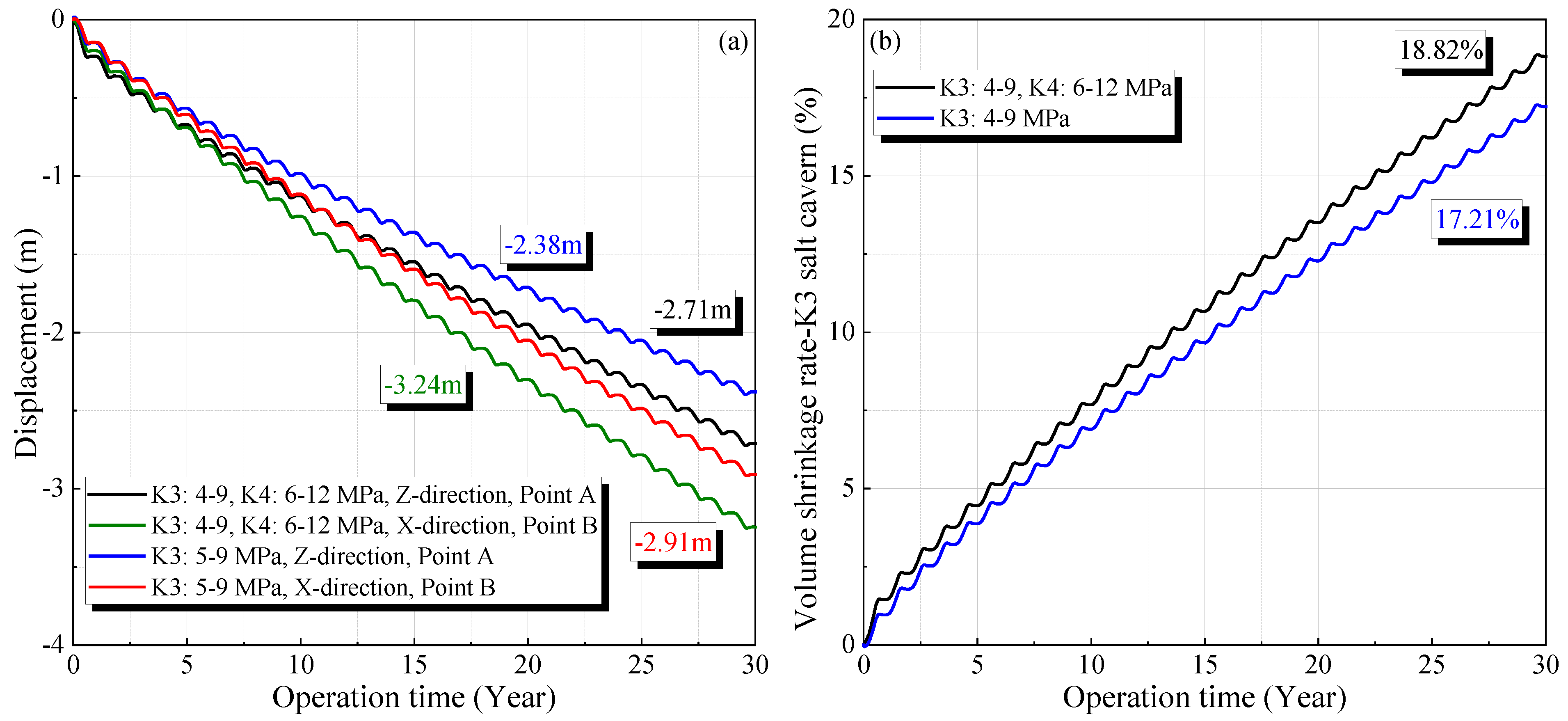
To investigate the effects of the salt caverns in other mining layers on stability, the displacement and volume shrinkage when the salt caverns are operated in a single mining layer were compared with the results presented in Section 3.1. Figure 11 and Figure 12 show the changes in the displacement and volume reduction rate for the salt caverns in the K3 and K4 mining layers, respectively (the locations of Points A, B, and C are shown in Figure 5). When only the salt cavern in the K3 mining layer is used, the maximum displacements in the horizontal and vertical directions after 30 years are 2.91 and 2.38 m, respectively. The volume shrinkage rate of the salt cavern in the K3 mining layer after 30 years is 17.21% under operational pressures of 4–9 MPa. These values are lower than the corresponding results when two mining layers are simultaneously used, which are 3.24 m, 2.71 m, and 18.82%, respectively.
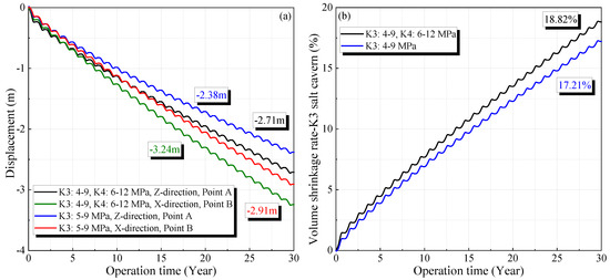
Figure 11.
Variation of the displacement (a) and volume shrinkage rate (b) in K3 salt cavern compared with a single mining layer.
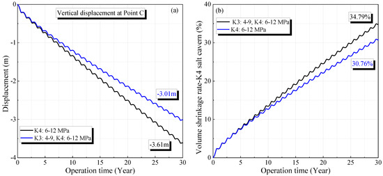
Figure 12.
Variation of the displacement (a) and volume shrinkage rate (b) in K4 salt cavern compared with a single mining layer.
A similar phenomenon is observed when only the salt cavern in the K4 mining layer is used. Under operational pressures of 6–12 MPa in the salt cavern of the K4 mining layer, the maximum displacement in the vertical direction and volume shrinkage rate after 30 years of operation are 3.01 m and 30.76%, respectively. These values are lower than those obtained when the salt cavern in the K3 mining layer also operated under gas pressures of 4–9 MPa. The corresponding displacement and volume shrinkage rate are 3.61 m and 34.79%, respectively.
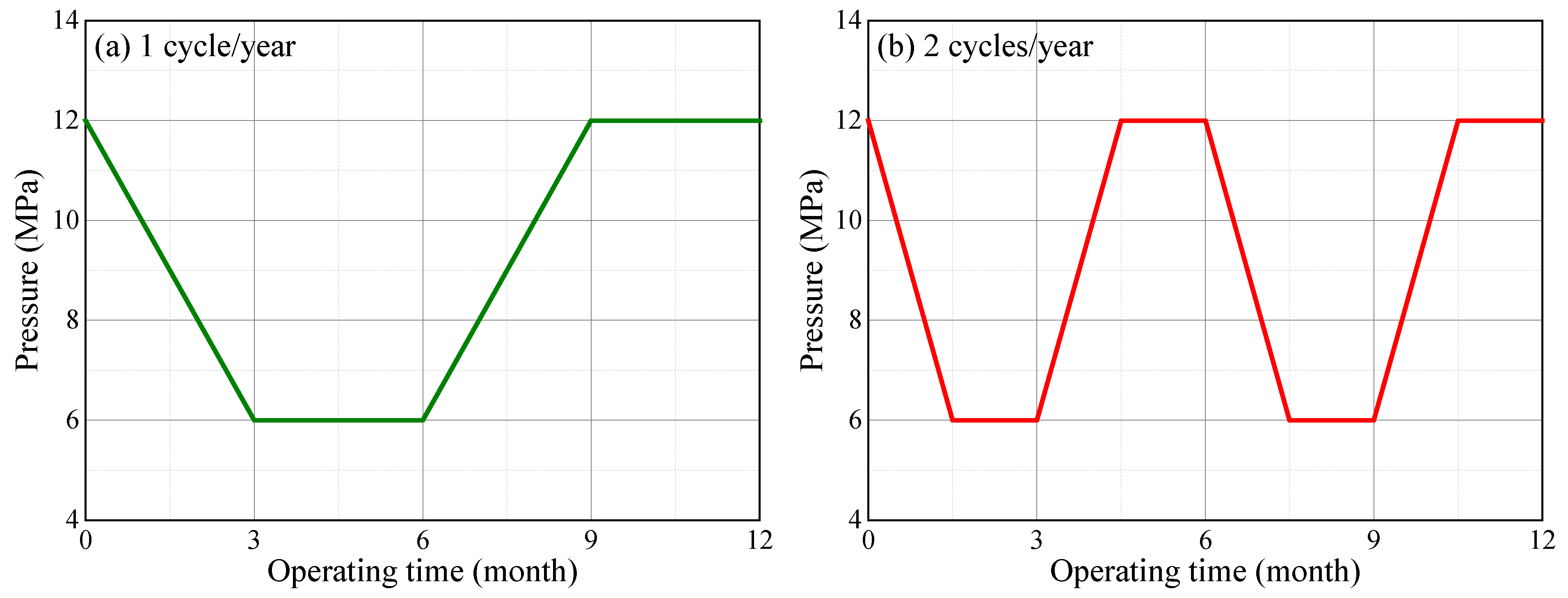
3.3. Effects of Cyclic Period
Because the salt cavern gas storage may experience injection–withdrawal several times owing to the peak shaving requirement, the effect of the cyclic period of gas pressure on cavern stability was analyzed. As shown in Figure 13, the cyclic period was set as one year or half a year based on the actual operational mode in Hubei Province, China. The duration of each stage for the two cyclic periods were 90 and 45 days. The operational pressures for the salt caverns in mining layers K3 and K4 were set to 5–9 and 7–12 MPa, respectively.
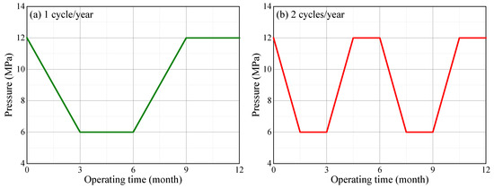
Figure 13.
Variation of the internal pressure in the K4 salt cavern under different cyclic periods: (a) one cycle for one year and (b) two cycles for one year.
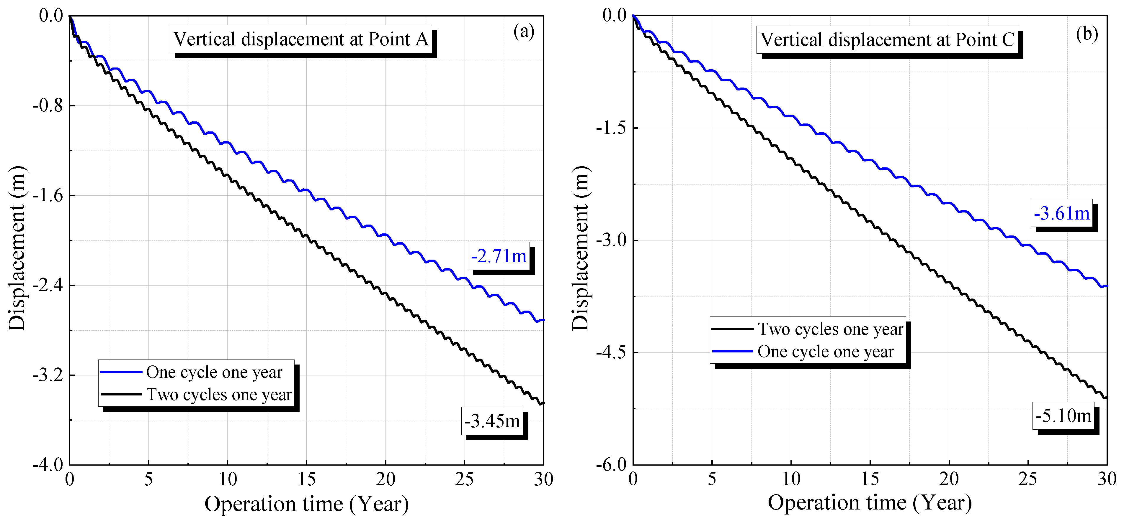
According to Figure 14, the volume shrinkage rates for the salt caverns in the K3 and K4 mining layers after operating for 30 years are 18.82% and 34.79%, respectively. These values are lower than the corresponding results when the cyclic period of the gas pressure is half a year, which are 25.11% and 48.28%, respectively. The curves of the volume shrinkage rate under different cyclic periods have a similar trend, increasing rapidly in the initial stage and tending to become steady with time. The volume reduction under the cyclic period of half a year is characterized by a larger increase rate in the stable stage compared with the cyclic period of one year. Similar characteristics can be observed for the displacement under different cyclic periods, as shown in Figure 15. The maximum displacements for the salt caverns in the K3 and K4 mining layers under a cyclic period of one year are 2.71 and 3.61 m, respectively. The corresponding values under the same gas pressures with a cyclic period of half a year are 3.45 and 5.10 m, respectively.
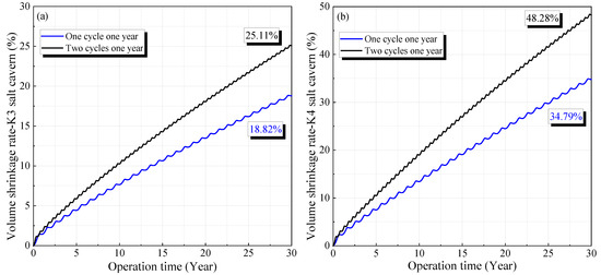
Figure 14.
Variation of volume shrinkage rate of the salt caverns under different cyclic periods during 30 years of operation: (a) one cycle for one year and (b) two cycles for one year.
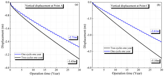
Figure 15.
Variation of displacement of the surrounding rock of the salt caverns under different cyclic periods during 30 years of operation: (a) one cycle for one year and (b) two cycles for one year.
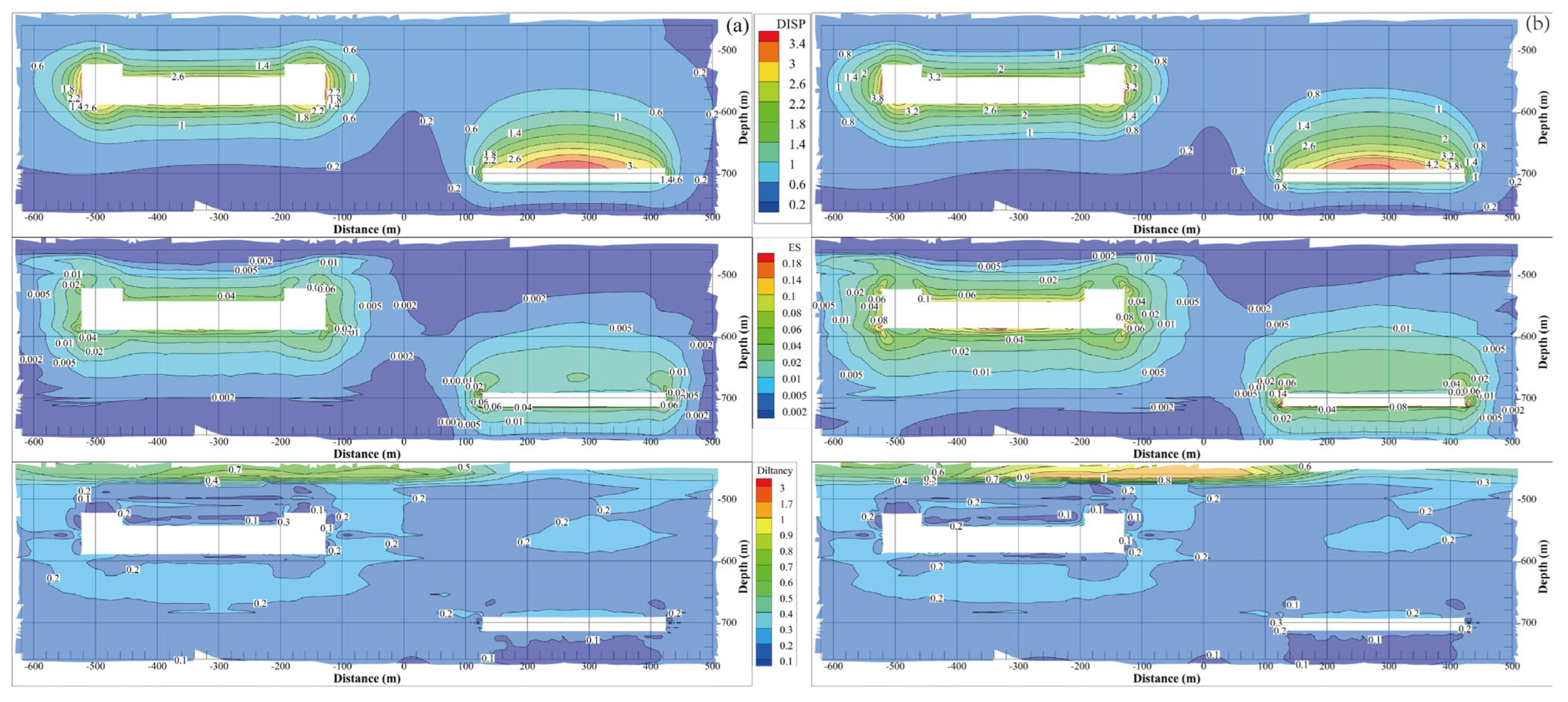
To comprehensively investigate the effect of the cyclic period on the cavern stability, Figure 16 presents a contour comparison of the displacement, equivalent strain, and dilatancy factor after 30 years of operation. Each evaluation factor contour shows a similar distribution behavior, which generally has a larger value around the cavern wall. After 30 years of operation, the maximum displacement, equivalent strain, and dilatancy factor under cyclic periods of one year and half a year are 2.825 and 5.230 m, 0.151 and 0.258, and 3.575 and 6.537, respectively. This means that increasing the frequency of injection–withdrawal has a negative effect on cavern stability.

Figure 16.
Contour comparison of different evaluation indices of the surrounding rock of the salt caverns under different cyclic periods: (a) one cycle for one year and (b) two cycles for one year.
4. Discussion
In this study, the horizontal cavern stabilities in two mining layers were analyzed under different operating pressures in the Yunying salt district, China. This utilization pattern in the two mining layers increases the natural gas storage capacity. The values of each evaluation index of the surrounding rock after 30 years of operation were analyzed, including the displacement, equivalent strain, dilatancy factor, and volume shrinkage. The results were compared with cases in which only the salt cavity in a single mining layer is excavated and operated. The influence of the cyclic period on cavern stability was examined further. Based on the investigation, one can conclude that simultaneously constructing salt cavern gas storage in two mining layers is feasible, and the operational pressure for the salt cavern in the K4 mining layer should be no less than 7 MPa to avoid excessive volume shrinkage. In this section, the main conclusions of the analysis of the horizontal caverns are discussed. Then, issues regarding the use of horizontal salt caverns in different mining layers in engineering practice are analyzed, and recommendations are made.
In terms of constructing a horizontal cavern in a bedded salt structure in China, several factors are essential for leaching a symmetric and sufficiently large cavern, including the alternation of injection and withdrawal, a large flow rate, and an oil blanket. Caverns with an upper arch and a lower slope have the best safety [48]. Irregular shapes may lead to dilatancy and an unstable cavern wall [49]. To further describe the cavern outline, it is necessary to explore new technologies for the middle sections of horizontal caverns. The stability evaluation of the salt caverns in different mining layers is similar to that of the cavern group. Compared with a single salt cavern, a cavern group has a detrimental effect on stability. To quantitatively describe the degree of stability of the surrounding rock, Wang, et al. [50] proposed an element safety factor method based on the generalized Hoek–Brown fracture criterion and the stress distribution of the numerical calculation. Accordingly, the state of the surrounding rock can be classified as having high stability, poor stability, or instability. Zhang, et al. [51] established a physical model with four ellipsoid caverns and investigated the effects of various factors on cavern stability. The model test results were further compared with numerical simulation results, and it was concluded that the pillar width and pressure discrepancy between adjacent caverns operating together deserve more attention to ensure cavern group safety.
Constructing horizontal salt caverns is suitable for the bedded geological structure of the salt district, and has the advantages of a shorter leaching duration and greater gas storage capacity in comparison with a traditional cavern of a cylindrical shape [19]. To increase the utilization efficiency of salt mine resources, salt caverns in different mining layers are designed to be leached and operated simultaneously. According to the design experience in the Yunying salt district, the geometric parameters of the old mining caverns and the permeability of the rocks between mining layers should be highlighted. In addition to stability, the tightness of gas storage caverns in various mining layers should be analyzed in the future. When the interlayer between different mining layers has low permeability and ensures that the gas does not intrude, the caverns in one mining layer can be used to store natural gas, whereas those in other mining layers can be used as CAES caverns. Thus, investigating the cavern ability in different mining layers under high-frequency cyclic loading is recommended. Because increasing the frequency of injection–withdrawal increases the displacement of the surrounding rock of the salt cavern, the cavern stability is believed to be overestimated if there is more than one cycle of gas pressure in a year. This is consistent with the results obtained when a salt cavern is used for a CAES system. The maximum displacement of the surrounding rock of salt caverns with a cyclic period of one day is approximately twice as large as that of cases with a cyclic period of one year under the same operational pressures [8].
In line with a prior investigation [52], the temperature inside a salt cavern exhibits variation corresponding to changes in gas pressure. During the gas injection phase, the temperature within the cavern may rise due to gas compression. However, the magnitude of this temperature increase depends on various factors, including the gas injection rate, gas composition, and cavern dimensions. Conversely, during gas withdrawal, the cavern’s temperature tends to decrease. This phenomenon occurs because as gas is withdrawn, it undergoes expansion and cooling, resulting in a reduction of the cavern’s temperature. The rate of temperature decrease is influenced by both the rate of gas withdrawal and the initial conditions within the cavern. Heat transfer between the air and the cavern wall arises from temperature disparities [53]. The precise evolution of temperature and the interactions between the cavern and the rock salt can vary, contingent upon factors such as cavern depth, the geological characteristics of the salt formation, the type of gas being stored, and operational parameters.
It is widely acknowledged that the characteristics of salt layers can be profoundly affected by the presence of impurities, and the specific composition of the salt itself plays a pivotal role in shaping their mechanical behavior [54]. Impurities within salt layers can encompass a wide range of substances, including clay minerals, anhydrite, and various trace elements. These impurities can have significant consequences on the mechanical properties of salt. For instance, the presence of clay minerals can lead to a reduction in salt cohesion and an increase in permeability. Anhydrite, when present, may cause the salt to become more brittle and prone to fracturing. Understanding the types, concentrations, and distribution of impurities is paramount in assessing the suitability of salt formations for engineering applications. The chemical composition of salt layers, which can vary widely depending on geological conditions, is another critical determinant of their mechanical response [55]. Different salts and minerals, such as halite, sylvite, and carnallite, may coexist within salt formations. These variations in composition can result in distinct mechanical behaviors. For example, halite-dominated salt layers tend to exhibit greater ductility and deformation capacity, making them preferred candidates for cavern construction. In contrast, salt layers with a higher proportion of sylvite may exhibit increased brittleness and reduced ductility, impacting their suitability for certain engineering purposes.
5. Conclusions
To increase the storage capacity of natural gas and further use the salt-mining resources in the Yunying salt district, Hubei Province, China, salt caverns were designed as horizontal cavities and simultaneously constructed in two adjacent mining layers. The horizontal cavern stabilities in two mining layers were analyzed under different operational pressures. The geometric parameters of the salt caverns were determined according to the sonar test results, and a 3D geomechanical model was built based on the strata distribution information. The displacement, volume shrinkage rate, equivalent strain, and dilatancy factor were used to comprehensively evaluate the cavern stability. The influences of the cyclic period and caverns in adjacent mining layers on the cavern stability were further investigated. The main conclusions are summarized as follows:
- (1)
- Based on the strata information and sonar test results, the salt caverns in mining layers K3 and K4 in the Yunying salt district were designed and simplified as U-shaped and long tunnels, respectively. The length and height of the salt caverns in mining layers K3 and K4 were 400 and 300 m, and 70 and 25 m, respectively.
- (2)
- Based on the cavern responses after operation for 30 years under the evaluation criteria of displacement, volume shrinkage, equivalent strain, and dilatancy factor, the operational pressures for the salt caverns in the K3 and K4 mining layers should be no less than 4–9 and 7–12 MPa, respectively, to satisfy the stability requirements. The most important positions for cavern stability in the K3 and K4 mining layers are the middle part of the side and the middle area at the top, respectively.
- (3)
- In comparison with operating salt caverns in a single mining layer, using cavities in two mining layers simultaneously induces a larger volume reduction and displacement of the surrounding rock, which has a detrimental effect on cavern stability. Increasing the injection–withdrawal frequency of the gas pressure increases the deformation and volume reduction of the salt caverns.
- (4)
- A comprehensive analysis indicates that simultaneously constructing a salt cavern gas storage system in two mining layers is feasible and safe in the Yunying salt district of China.
Author Contributions
K.Z.: investigation, software, validation, methodology, formal analysis, writing—original draft. H.M.: conceptualization, methodology, formal analysis. Y.L. (Yinping Li): conceptualization, supervision, funding acquisition. Y.L. (Yuanxi Liu): investigation, methodology, formal analysis. R.C.: investigation, methodology. X.L.: methodology, formal analysis. S.H.: investigation, methodology. Z.Z.: investigation, methodology, formal analysis. X.W.: investigation, methodology. H.L.: funding acquisition, formal analysis. All authors have read and agreed to the published version of the manuscript.
Funding
This research was funded by the National Science Foundation for Excellent Young Scholars (No. 52122403), the Youth Innovation Promotion Association CAS (Grant No. 2019324), the Major Research Development Program of Hebei province (Grant No. 21374101D), the Major Research Development Program of Hubei province (Grant No. 2022BAA093, 2022BAD163), the Scientific and Technological Research Foundation for the Selected Returned Overseas Chinese Scholars (No. C20210304), the National Natural Science Foundation of China (No. U2034207) and the Major science and technology research and development project in Jiangxi Province (Grant No. 2023ACG01004).
Data Availability Statement
Not applicable.
Conflicts of Interest
The authors declare no conflict of interest.
References
- Blanco-Martín, L.; Rutqvist, J.; Battistelli, A.; Birkholzer, J.T. Coupled Processes Modeling in Rock Salt and Crushed Salt Including Halite Solubility Constraints: Application to Disposal of Heat-Generating Nuclear Waste. Transp. Porous Media 2018, 124, 159–182. [Google Scholar] [CrossRef]
- Cai, M.; Peng, H. Advance of in-situ stress measurement in China. J. Rock Mech. Geotech. Eng. 2011, 3, 373–384. [Google Scholar] [CrossRef]
- Chan, K.S.; Bodner, S.R.; Munson, D.E. Recovery and Healing of Damage in WIPP Salt. Int. J. Damage Mech 1998, 7, 143–166. [Google Scholar] [CrossRef]
- Chen, J.; Chen, H.; Wu, F.; Jiang, D.; Zhang, H.; Gao, R.; Ding, B. Creep Properties of Mudstone Interlayer in Bedded Salt Rock Energy Storage Based on Multistage Creep Test: A Case Study of Huai’an Salt Mine, Jiangsu Province. Geofluids 2022, 2022, 2012776. [Google Scholar] [CrossRef]
- Chen, J.; Lu, D.; Liu, W.; Fan, J.; Jiang, D.; Yi, L.; Kang, Y. Stability study and optimization design of small-spacing two-well (SSTW) salt caverns for natural gas storages. J. Energy Storage 2020, 27, 101131. [Google Scholar] [CrossRef]
- Chen, X.; Li, Y.; Shi, Y.; Yu, Y.; Jiang, Y.; Liu, Y.; Dong, J. Tightness and stability evaluation of salt cavern underground storage with a new fluid–solid coupling seepage model. J. Pet. Sci. Eng. 2021, 202, 108475. [Google Scholar] [CrossRef]
- Cosenza, P.; Ghoreychi, M.; Bazargan-Sabet, B.; De Marsily, G. In situ rock salt permeability measurement for long term safety assessment of storage. Int. J. Rock Mech. Min. Sci. 1999, 36, 509–526. [Google Scholar] [CrossRef]
- Deng, J.Q.; Yang, Q.; Liu, Y.R.; Pan, Y.W. Stability evaluation and failure analysis of rock salt gas storage caverns based on deformation reinforcement theory. Comput. Geotech. 2015, 68, 147–160. [Google Scholar] [CrossRef]
- Durup, J.G.; Vidal, F.; Rolin, C. Pilot Abandonment Test of a Very Deep Gas Storage Salt Cavern. Oil Gas Sci. Technol. 2007, 62, 287–296. [Google Scholar] [CrossRef]
- Habibi, R.; Moomivand, H.; Ahmadi, M.; Asgari, A. Stability analysis of complex behavior of salt cavern subjected to cyclic loading by laboratory measurement and numerical modeling using LOCAS (case study: Nasrabad gas storage salt cavern). Environ. Earth Sci. 2021, 80, 317. [Google Scholar] [CrossRef]
- Han, Y.; Cui, H.; Ma, H.; Chen, J.; Liu, N. Temperature and pressure variations in salt compressed air energy storage (CAES) caverns considering the air flow in the underground wellbore. J. Energy Storage 2022, 52, 104846. [Google Scholar] [CrossRef]
- ICG, Inc. Advanced Grid Generation for Engineers and Scientists Griddle and BlockRanger User’s Guide; ICG, Inc.: Minneapolis, MN, USA, 2017. [Google Scholar]
- Itasca-Consulting Group. FLAC3D 6.0 Theory and Background; Itasca-Consulting Group: Minneapolis, MN, USA, 2017. [Google Scholar]
- Jaeger, J.C.; Cook, N.G.; Zimmerman, R. Fundamentals of Rock Mechanics; John Wiley & Sons: Hoboken, NJ, USA, 2009. [Google Scholar]
- Jiang, D.; Wang, Y.; Liu, W.; Li, L.; Qiao, W.; Chen, J.; Li, D.; Li, Z.; Fan, J. Construction simulation of large-spacing-two-well salt cavern with gas blanket and stability evaluation of cavern for gas storage. J. Energy Storage 2022, 48, 103932. [Google Scholar] [CrossRef]
- Khaledi, K.; Mahmoudi, E.; Datcheva, M.; Schanz, T. Stability and serviceability of underground energy storage caverns in rock salt subjected to mechanical cyclic loading. Int. J. Rock Mech. Min. Sci. 2016, 86, 115–131. [Google Scholar] [CrossRef]
- Kushnir, R.; Dayan, A.; Ullmann, A. Temperature and pressure variations within compressed air energy storage caverns. Int. J. Heat Mass Transf. 2012, 55, 5616–5630. [Google Scholar] [CrossRef]
- Lankof, L.; Urbańczyk, K.; Tarkowski, R. Assessment of the potential for underground hydrogen storage in salt domes. Renew. Sustain. Energy Rev. 2022, 160, 112309. [Google Scholar] [CrossRef]
- Li, H.; Wanyan, Q.; Ding, G.; Li, K.; Kou, Y.; Bai, S.; Ran, L.; Wu, J.; Deng, J. Geomechanical Feasibility Analysis of Salt Cavern Gas Storage Construction in Sanshui Basin, Guangdong Province. Eng 2022, 3, 709–731. [Google Scholar] [CrossRef]
- Li, J.; Wan, J.; Liu, H.; Jurado, M.J.; He, Y.; Yuan, G.; Xia, Y. Stability Analysis of a Typical Salt Cavern Gas Storage in the Jintan Area of China. Energies 2022, 15, 4167. [Google Scholar] [CrossRef]
- Li, J.; Zhang, N.; Xu, W.; Naumov, D.; Fischer, T.; Chen, Y.; Zhuang, D.; Nagel, T. The influence of cavern length on deformation and barrier integrity around horizontal energy storage salt caverns. Energy 2022, 244, 123148. [Google Scholar] [CrossRef]
- Li, Q.; Ning, Z.; Liu, J.; Xu, W.; Zhan, L.; Liu, J.; Chen, Y.; Shi, X.; Chen, X.; Li, J. Stability and economic evaluation of multi-step horizontal salt caverns with different step distances in bedded salt formations. J. Energy Storage 2023, 57, 106192. [Google Scholar] [CrossRef]
- Liu, W.; Jiang, D.; Chen, J.; Daemen, J.J.K.; Tang, K.; Wu, F. Comprehensive feasibility study of two-well-horizontal caverns for natural gas storage in thinly-bedded salt rocks in China. Energy 2018, 143, 1006–1019. [Google Scholar] [CrossRef]
- Norton, F.H. The Creep of Steel at High Temperatures, 1st ed.; McGraw-Hill Book Company, Incorporated: New York, NY, USA, 1929. [Google Scholar]
- Peng, T.; Wan, J.; Liu, W.; Li, J.; Xia, Y.; Yuan, G.; Jurado, M.J.; Fu, P.; He, Y.; Liu, H. Choice of hydrogen energy storage in salt caverns and horizontal cavern construction technology. J. Energy Storage 2023, 60, 106489. [Google Scholar] [CrossRef]
- Rhinoceros, I. Rhinoceros 6 User’s Manual; Rhinoceros, I., Ed.; Robert McNeel & Associates: Seattle, WA, USA, 2018. [Google Scholar]
- Shahmorad, Z.; Salarirad, H.; Molladavoudi, H. A study on the effect of utilizing different constitutive models in the stability analysis of an underground gas storage within a salt structure. J. Nat. Gas Sci. Eng. 2016, 33, 808–820. [Google Scholar] [CrossRef]
- Song, Y.; Song, R.; Liu, J. Hydrogen tightness evaluation in bedded salt rock cavern: A case study of Jintan, China. Int. J. Hydrogen Energy 2023, 48, 30489–30506. [Google Scholar] [CrossRef]
- Tackie-Otoo, B.N.; Haq, M.B. A comprehensive review on geo-storage of H2 in salt caverns: Prospect and research advances. Fuel 2024, 356, 129609. [Google Scholar] [CrossRef]
- Van Sambeek, L.L.; Ratigan, J.L.; Hansen, F.D. Dilatancy of rock salt in laboratory tests. Int. J. Rock Mech. Min. Sci. Geomech. Abstr. 1993, 30, 735–738. [Google Scholar] [CrossRef]
- Wang, G.; Xing, W.; Liu, J.; Hou, Z.; Were, P. Influence of water-insoluble content on the short-term strength of bedded rock salt from three locations in China. Environ. Earth Sci. 2015, 73, 6951–6963. [Google Scholar] [CrossRef]
- Wang, H.-x.; Zhang, B.; Fu, D.; Ndeunjema, A. Stability and airtightness of a deep anhydrite cavern group used as an underground storage space: A case study. Comput. Geotech. 2018, 96, 12–24. [Google Scholar] [CrossRef]
- Wang, J.; Wang, X.; Zhang, Q.; Song, Z.; Zhang, Y. Dynamic prediction model for surface settlement of horizontal salt rock energy storage. Energy 2021, 235, 121421. [Google Scholar] [CrossRef]
- Wang, J.; Zhang, Q.; Song, Z.; Feng, S.; Zhang, Y. Nonlinear creep model of salt rock used for displacement prediction of salt cavern gas storage. J. Energy Storage 2022, 48, 103951. [Google Scholar] [CrossRef]
- Wang, T.; Yang, C.; Chen, J.; Daemen, J.J.K. Geomechanical investigation of roof failure of China’s first gas storage salt cavern. Eng. Geol. 2018, 243, 59–69. [Google Scholar] [CrossRef]
- Wang, T.; Yang, C.; Ma, H.; Li, Y.; Shi, X.; Li, J.; Daemen, J.J.K. Safety evaluation of salt cavern gas storage close to an old cavern. Int. J. Rock Mech. Min. Sci. 2016, 83, 95–106. [Google Scholar] [CrossRef]
- Wang, T.; Yang, C.; Yan, X.; Li, Y.; Liu, W.; Liang, C.; Li, J. Dynamic response of underground gas storage salt cavern under seismic loads. Tunn. Undergr. Space Technol. 2014, 43, 241–252. [Google Scholar] [CrossRef]
- Wang, T.T.; Ma, H.L.; Shi, X.L.; Yang, C.H.; Zhang, N.; Li, J.L.; Ding, S.L.; Daemen, J.J.K. Salt cavern gas storage in an ultra-deep formation in Hubei, China. Int. J. Rock Mech. Min. Sci. 2018, 102, 57–70. [Google Scholar] [CrossRef]
- Wang, X.; Wang, J.; Zhang, Q.; Song, Z.; Liu, X.; Feng, S. Long-term stability analysis and evaluation of salt cavern compressed air energy storage power plant under creep-fatigue interaction. J. Energy Storage 2022, 55, 105843. [Google Scholar] [CrossRef]
- Wang, Y.; Zhang, X.; Jiang, D.; Liu, W.; Wan, J.; Li, Z.; Fan, J.; Wang, W. Study on stability and economic evaluation of two-well-vertical salt cavern energy storage. J. Energy Storage 2022, 56, 106164. [Google Scholar] [CrossRef]
- Wu, W.; Hou, Z.; Yang, C. Investigations on Evaluating Criteria of Stabilities For Energy (Petroleum and Natural Gas) Storage Caverns in Rock Salt. Chin. J. Rock Mech. Eng. 2005, 24, 2497–2505. [Google Scholar]
- Xing, W.; Zhao, J.; Hou, Z.; Were, P.; Li, M.; Wang, G. Horizontal natural gas caverns in thin-bedded rock salt formations. Environ. Earth Sci. 2015, 73, 6973–6985. [Google Scholar] [CrossRef]
- Yan, Z.; Wang, Z.; Wu, F.; Lyu, C. Stability analysis of Pingdingshan pear-shaped multi-mudstone interbedded salt cavern gas storage. J. Energy Storage 2022, 56, 105963. [Google Scholar] [CrossRef]
- Yang, C.; Daemen, J.J.K.; Yin, J.-H. Experimental investigation of creep behavior of salt rock. Int. J. Rock Mech. Min. Sci. 1999, 36, 233–242. [Google Scholar] [CrossRef]
- Yang, C.; Wang, T.; Qu, D.; Ma, H.; Li, Y.; Shi, X.; Daemen, J.J.K. Feasibility analysis of using horizontal caverns for underground gas storage: A case study of Yunying salt district. J. Nat. Gas Sci. Eng. 2016, 36, 252–266. [Google Scholar] [CrossRef]
- Yuan, G.; Wan, J.; Li, J.; Li, G.; Xia, Y.; Ban, F.; Zhang, H.; Jurado, M.J.; Peng, T.; Liu, W. Stability analysis of a typical two-well-horizontal saddle-shaped salt cavern. J. Energy Storage 2021, 40, 102763. [Google Scholar] [CrossRef]
- Zhang, G.; Liu, Y.; Wang, T.; Zhang, H.; Wang, Z.; Zhao, C.; Chen, X. Pillar stability of salt caverns used for gas storage considering sedimentary rhythm of the interlayers. J. Energy Storage 2021, 43, 103229. [Google Scholar] [CrossRef]
- Zhang, G.; Wang, Z.; Liu, J.; Li, Y.; Cui, Z.; Zhang, H.; Wang, L.; Sui, L. Stability of the bedded key roof above abandoned horizontal salt cavern used for underground gas storage. Bull. Eng. Geol. Environ. 2020, 79, 4205–4219. [Google Scholar] [CrossRef]
- Zhang, G.; Zhang, H.; Liu, Y.; Wang, T.; Wang, Z. Surrounding rock stability of horizontal cavern reconstructed for gas storage. J. Energy Storage 2023, 59, 106534. [Google Scholar] [CrossRef]
- Zhang, Q.; Liu, J.; Wang, L.; Luo, M.; Liu, H.; Xu, H.; Zou, H. Impurity Effects on the Mechanical Properties and Permeability Characteristics of Salt Rock. Energies 2020, 13, 1366. [Google Scholar] [CrossRef]
- Zhang, Q.Y.; Duan, K.; Jiao, Y.Y.; Xiang, W. Physical model test and numerical simulation for the stability analysis of deep gas storage cavern group located in bedded rock salt formation. Int. J. Rock Mech. Min. Sci. 2017, 94, 43–54. [Google Scholar] [CrossRef]
- Zhao, C.; Chen, B. China’s oil security from the supply chain perspective: A review. Appl. Energy 2014, 136, 269–279. [Google Scholar] [CrossRef]
- Zhao, K.; Liu, Y.; Li, Y.; Ma, H.; Hou, W.; Yu, C.; Liu, H.; Feng, C.; Yang, C. Feasibility analysis of salt cavern gas storage in extremely deep formation: A case study in China. J. Energy Storage 2022, 47, 103649. [Google Scholar] [CrossRef]
- Zhao, K.; Ma, H.; Li, H.; Yang, C.; Li, P.; Liu, Y.; Li, H.; Zeng, Z.; Wang, X. Stability analysis of CAES salt caverns using a creep-fatigue model in Yunying salt district, China. J. Energy Storage 2023, 62, 106856. [Google Scholar] [CrossRef]
- Zhao, K.; Ma, H.; Zhou, J.; Yin, H.; Li, P.; Zhao, A.; Shi, X.; Yang, C. Rock Salt Under Cyclic Loading with High-Stress Intervals. Rock Mech. Rock Eng. 2022, 55, 4031–4049. [Google Scholar] [CrossRef]


Disclaimer/Publisher’s Note: The statements, opinions and data contained in all publications are solely those of the individual author(s) and contributor(s) and not of MDPI and/or the editor(s). MDPI and/or the editor(s) disclaim responsibility for any injury to people or property resulting from any ideas, methods, instructions or products referred to in the content. |
© 2023 by the authors. Licensee MDPI, Basel, Switzerland. This article is an open access article distributed under the terms and conditions of the Creative Commons Attribution (CC BY) license (https://creativecommons.org/licenses/by/4.0/).