Article

Research on Heat Generation Law and Cooling System Performance of Hydraulic System of Combined Machine Tool

1
Ningbo Innovation Center, Zhejiang University, Ningbo 315100, China
2
State Key Laboratory of Fluid Power and Mechatronic Systems, Zhejiang University, Hangzhou 310027, China
3
School of Mechanical Engineering, Zhejiang University, Hangzhou 310013, China
*
Authors to whom correspondence should be addressed.
Energies 2023, 16(21), 7322; https://doi.org/10.3390/en16217322
Submission received: 15 September 2023 / Revised: 19 October 2023 / Accepted: 26 October 2023 / Published: 28 October 2023
(This article belongs to the Section J: Thermal Management)

Abstract

:
After the machine tool works continuously, the temperature of the hydraulic system continues to rise, which affects the work efficiency of the machine tool. Therefore, it is very important to control the temperature within a reasonable range. This paper proposes an improved scheme to replace a single fan with dual fans to improve the heat dissipation capacity of the radiator. Starting from the principle of heat exchange between oil and air, the relationship between the oil temperature and the wind speed on the face of the heat exchanger is derived, and the theoretical basis of the cooling system is given. Combined with logic control, the fan has the advantages of fast action, high efficiency and low energy consumption, which ensures the efficient and reliable operation of the machine tool. A one-dimensional simulation model of the thermal hydraulic system is established, and the heat generation and heat dissipation power of each element are calculated. Among them, the heat dissipation of the radiator is the largest, accounting for about 55% of the total heat dissipation. The experimental results show that the optimal fan speed is 3200 r/min and the flow rate is 0.2 m3/s at 26 °C. The thermal balance temperature of the hydraulic system is reduced from the original 65 °C to 58 °C, and its cooling capacity meets the requirements of a high-altitude and high-temperature environment.

1. Introduction

A good cooling and heat dissipation system can ensure the safe and reliable operation of equipment, with low energy consumption, a low maintenance rate and high work efficiency. Once the cooling and cooling system fails, it will cause the equipment components to heat up severely due to the heat generated during the working process, which will eventually cause the equipment to malfunction or even be damaged. Countless machine tools have been disabled due to poor heat dissipation performance, which has brought great losses. Therefore, it is particularly important to study the cooling and heat dissipation system of machine-tool equipment [1]. In recent years, equipment using hydraulic transmission systems and servo control systems has been widely used in various fields with the continuous development of society [2]. The hydraulic system occupies a crucial position in the machining field such as machine tools by virtue of its advantages of small size, light weight, smooth movement, and stepless speed regulation in a large range [3]. In actual production, the diagnosis of hydraulic-system faults is not very fast, accurate or effective. Most of the related technical personnel do not have enough understanding of the principles and methods of hydraulic-system fault diagnosis, which has caused certain economic losses to the production of enterprises [4]. Various pipelines, hydraulic cylinders and hydraulic pumps of machine tools are in a sealed state, and the internal state of the system is not easy to directly check. The damage to the hydraulic transmission system is far greater than that of the mechanical transmission system, and it is inconvenient to carry out instrumentation [5]. As the main power system of machine tools, the hydraulic system has a compact mechanical structure and can ensure the normal operation of machine tools. One of the main factors affecting the operation of the machine tool is the oil temperature of the lubricating oil such as the gear oil in the machine tool. As the working medium of the hydraulic system, the temperature of hydraulic oil directly affects the efficiency of the hydraulic system, which in turn affects the normal operation of the machine tool. In general, it is ideal to keep the oil temperature around 40–50 °C, which can maximize the efficiency of the hydraulic system. However, due to unreasonable system design factors such as the unreasonable matching of hydraulic components, or the type and viscosity of the oil not meeting the standard, a large amount of heat will be generated inside the hydraulic system, which will make the hydraulic oil temperature too high. On the other hand, the cooling effect of the hydraulic system is not good, and the heat cannot be dissipated in time, which will also cause the oil temperature to rise. Excessive oil temperature in the hydraulic system will have many adverse effects on CNC machine tools. In order to effectively prevent and control the occurrence of high oil temperature, improving the heat dissipation performance of the hydraulic system is an important factor [6,7,8,9].
As we all know, the fan speed needs to be reasonably matched with the cooling requirements of the cooling system to avoid overcooling or overheating. In order not to cause deformation of the workpiece affecting the machining accuracy and avoid burning the tool, reliable cooling is required [10]. The hydraulic oil of the machine tool adopts the air cooling mode, and the cooling system of the machine tool will have insufficient heat dissipation capacity in the extreme high temperature and plateau environment [11]. If the hydraulic oil temperature is too high, the hydraulic actuators will be weak and the working action will be sluggish, which will seriously affect the working efficiency of the product [12]. A problem that cannot be ignored is that the air density decreases by about 8% to 9% for every 1000 m rise in altitude. The heat dissipation capacity of air-cooled equipment using air as the cooling medium is greatly reduced in high-altitude environments [13]. At the same time, the increase of the ambient temperature reduces the liquid-air temperature difference and reduces the heat dissipation efficiency [14]. Due to the high temperature of the oil, problems such as many machine tool failures and reduced efficiency will eventually occur [15]. Therefore, eliminating the heat load in the oil and lowering the temperature plays a vital role in the stable and reliable operation of the machine tool [16].
The temperature rise problem of the hydraulic system is not only an important factor affecting the normal performance of the system, but also the temperature change will cause greater interference to the control accuracy [17]. Zhang [18] clarified the main heat-generating and heat-dissipating components through experimental data, optimized the design of various parameters of the system and analyzed the influence on the thermal equilibrium temperature. Lu [19] established a heat exchange model of the hydraulic system to study the effect of changing the flow rate through the radiator and using a load-sensitive system on the thermal equilibrium temperature. Xie [20] derived mathematical models of hydraulic pumps, multi-way valves, radiators, etc., based on the principles of energy and mass conservation, and analyzed the temperature changes of the system under different working conditions. Xu [21] divided the hydraulic system components into resistive components and capacitive components, and established a hydraulic system heat exchange model based on the bonded power diagram. Zheng [22] analyzed the influence of the pressure of the hydraulic system of the lifting loader on the power consumption. The research showed that the power loss of the new system was significantly reduced, and the thermal equilibrium temperature of the system was also greatly reduced. Chen [23] analyzed the heat generation principle and heat dissipation path of the hydraulic system of the skid steer, combined with the results of the heat balance test to improve the confluence valve and radiator. After the improvement, the system temperature decreased under different working conditions. Zhou [24] studied the influence of the arrangement of the radiator in the engine compartment of the loader on the heat dissipation performance of the vehicle, and used the wind tunnel test to analyze the heat dissipation of the hydraulic system and transmission system. Kwon [25] designed a new type of plate-fin liquid cooling radiator with guide vanes to control the heat balance temperature of the system in a reasonable range, aiming at the problem of insufficient heat dissipation capacity of the loader hydraulic system in summer. Hui [26] established a heat exchange model of a dual-pressure plunger pump, and compared it with a constant-pressure variable pump to analyze its temperature rise and efficiency characteristics. There are many factors for the high oil temperature, mainly including unreasonable system design, relatively large mechanical loss, relatively large flow rate and relatively high viscosity of oil, or relatively high ambient temperature and poor heat dissipation. At the same time, if a large amount of oil flows back into the oil tank through the overflow valve during the working process, it will also cause the oil temperature to rise continuously [27].
The existing literature mainly studies the internal structure of the radiator, but the research on the overall cooling efficiency of the machine tool cooling system is less. In order to meet the needs of higher spindle speeds, new lubrication and cooling methods have emerged. These new lubrication and cooling methods not only reduce the temperature rise of the bearing, but also reduce the temperature difference between the inner and outer rings of the bearing to ensure that the thermal deformation of the spindle is small. Excessive oil temperature in the hydraulic system of the machine tool will cause many hazards, which will cause thermal deformation of mechanical components, resulting in system leakage or jamming. It will also greatly affect the machining accuracy of the machine tool and the working pressure of the hydraulic system. By improving the heat dissipation conditions, rationally designing the hydraulic-circuit structure, selecting reasonable hydraulic components, and improving the installation accuracy of the hydraulic circuit, the condition of excessive oil temperature can be effectively solved. Aiming at the problem that the oil temperature of a certain type of machine tool is too high, this paper proposes an improvement plan to replace a single fan with double fans to improve the heat dissipation capacity of the radiator. The one-dimensional simulation method is used to calculate the hydraulic oil cooling system of a multi-function drilling rig, and the results show that its cooling capacity meets the requirements of plateau and high-temperature environments. After verification of the heat balance of the whole vehicle, the cooling effect of the improved scheme was significantly improved, and the adaptability of this model to plateau and high temperature environments was improved.

2. Heat Generation Mechanism of Hydraulic System

2.1. Working Mode

As the main power system of the compound machine tool, the hydraulic system has a compact mechanical structure and can ensure the normal operation of the machine tool. Therefore, strengthening the research on the fault diagnosis of the hydraulic system of the machine tool has strong practical significance for improving the operating efficiency of the machine tool. The hydraulic system of the machine tool mainly provides the drive for the key components of the machine tool such as the rotary tool rest, the tool rest, the hydrostatic guide rail, and the hydraulic chuck. The system is mainly composed of four parts: the computer control part, servo speed regulation part, pump control cylinder power system and pressure sensor, as shown in Figure 1. When the system is working, the pressure and flow from the gear pump to the rotary hydraulic cylinder are controlled by adjusting the speed of the motor. The control part compares the pressure signal detected by the pressure sensor with the set pressure to obtain the pressure deviation. According to the deviation signal, the motor controller adjusts the pressure and flow delivered by the pump to the rotary hydraulic cylinder, thereby stabilizing the preset clamping force of the hydraulic chuck. The reciprocating motion of each hydraulic cylinder is controlled by the three-position four-way reversing valve to adjust the working state of the sliding table. The liquid is decompressed after passing through the electro-hydraulic proportional pressure-reducing valve. By changing the working position of the electromagnetic reversing valve, the movement direction of the piston of the rotary hydraulic cylinder is changed to realize the clamping or loosening of the chuck. Among them, the hydraulic lock composed of two hydraulic control check valves can ensure that the position of the piston of the rotary hydraulic cylinder and the pressure of the high-pressure chamber remain unchanged after the system is shut down due to failure, so as to avoid the accident of the work piece flying out. During the broaching process of the machine tool, hydraulic oil is injected into the lower chamber of the hydraulic cylinder, and the oil is returned to the upper part and the solenoid valve spool is disconnected. Another solenoid valve is pulled in to realize the conversion of the oil circuit, so that the piston rod moves upwards. After moving to the limit position, the limit switches will feedback the position arrival signal to realize the broaching action. The on-off of the solenoid valve or the requirements of different speed gears can realize speed regulation. After the knife is installed or the speed regulation is completed, the solenoid valve will automatically disconnect. In the process of loosening the knife, the lower part of the hydraulic cylinder is connected to the oil. The upper part is injected with hydraulic oil, and the lower chamber of the cylinder is connected to the oil. Then, both solenoid valves are powered on at the same time to switch the oil circuit so that the piston rod moves down. After moving to the limit position, the limit switches will feedback the position arrival signal, and then realize the loosening action. The oil supply of the hydraulic system is realized by the motor-driven hydraulic pump, which also provides power for the lubrication of the headstock.

2.2. Mathematical Model of Hydraulic System

The function of the hydraulic system in the combined machine tool is to provide stable pressure for the hydraulic chuck, hydraulic tailstock and hydraulic turret. The flow equation of the orifice is as follows [28]
Q = d A 2 ( P 1 P 2 ) / ρ
where Q is the flow through the orifice; A is the flow area of the valve port; P1 and P2 are the pressure before and after throttling, respectively; and ρ is the density of the oil.
Priority valve spool balance equation [28]:
P 1 A 1 = P 2 A 1 + k x
where A 1 is the end face area of the priority valve spool; k is the priority valve control spring stiffness; and x is the priority valve control spring compression.
The displacement of the hydraulic pump is calculated as follows [29]:
V p = q p n p
where n p is the rotational speed; q p is the flow rate.
According to the operating principle of the pilot-operated relief valve, the force balance equation of the main valve spool is deduced as [29]
m 1 x ¨ = p 1 A 1 p 2 A 2 k ( x 0 + x ) F V F s
where A 1 and p 1 are the cross-sectional area and pressure; A 2 and p 2 are the cross-sectional area and pressure; F V is the viscous friction force on the valve spool; and F s is the steady-state hydrodynamic force.
The force balance equation for the pilot valve spool is [30]
p 4 A x = k D 1 i k D 2 x + C d π d x sin ( 2 φ ) p 4
where k D 1 is the current-force gain factor; i is the current in the coil; and φ is the spool half-cone angle.
The efficiency–heat transfer unit-number method is a special thermal calculation method for calculating internal heat exchangers. Its main principles are as follows [30]:
C = m i n [ ( m ˙ C p ) h , ( m ˙ C p ) c ] m a x [ ( m ˙ C p ) h , ( m ˙ C p ) c ]
where m ˙ is mass flow rate; C p is specific heat at constant pressure.
The number of heat transfer units (NTU) together with the heat capacity ratio and efficiency determine the dimensionless parameters of the performance of the radiator, expressed as [30]
N T U = U A m i n [ ( m ˙ C p ) h , ( m ˙ C p ) c ]
where U is the total heat transfer coefficient; A is the heat transfer area.
There are many pipelines in the hydraulic system, and the pressure drop of the pipeline is mainly caused by the resistance loss along the way and the local pressure loss, namely [30]
Δ p = λ l d ρ v 2 2 + ξ ρ v 2 2
The pressure loss of the pipeline is all converted into heat, and the heat generation power is [30]
Φ = Δ p Q = ( λ l d ρ v 2 2 + ξ ρ v 2 2 ) Q
The heat of the oil conducts convective heat exchange with the inner wall of the pipeline, and the heat is then conducted from the inner wall of the pipeline to the outer wall, and then conducts convective heat exchange and radiation heat exchange with the air.
Convective heat exchange between fuel tank and air [31]:
Q = k A Δ t
where k is the overall heat transfer coefficient; A is the heat dissipation area; and Δt is the temperature difference inside and outside the tank.
The convective heat transfer process of the pipeline is similar to that of the oil tank. The radioactive heat transfer calculation adopts a relatively simple model. The formula of radiant heat transfer rate is [31]
q = ε σ ( T i 4 T j 4 )
where ε is the emissivity; σ is the Steffen–Bailsman constant; Ti is the surface temperature of the shell; and Tj is the ambient temperature.

2.3. Heat Generation Mechanism of Hydraulic System

According to the schematic diagram of the hydraulic system of the machine tool, a simulation model of the hydraulic system of the working device is established in AMESim. When modeling hydraulic components, the flow area of the valve port, the position limitation of the valve core and the valve body and the relative motion relationship are mainly considered. In AMESim, control signals −1, 0, 1 are used to control the open and closed states of the valve. When the multi-way valve is in the neutral position, the hydraulic oil of the hydraulic system of the working device is unloaded through the mid-position low pressure of the multi-way valve. The principle of the hydraulic system is shown in Figure 2, and the physical property parameters of the hydraulic oil are shown in Table 1.
When the working device is working, the pressure of the hydraulic system rises rapidly. At this time, the maximum pressure of the cylinder, piston and cylinder is 5.7 MPa, as shown in Figure 3a. Due to the action of the drag torque, the outlet pressure of the hydraulic pump oscillates violently. During the return trip, the large cavity of the cylinder enters oil and the small cavity returns oil. The pressure change trend and value of the large cavity are consistent with the pump outlet pressure. The pressure of the small cavity oscillates slightly, and its value is about 2 MPa. Therefore, the pressure should be adjusted within the specified range; otherwise the oil temperature of the system will rise if it exceeds the allowable pressure range. It can be seen from Figure 3b that the oil input into the large cavity of the cylinder is 17 L/min at the beginning, and the oil flow is 23 L/min after running for a few seconds; the flow oscillates at 6 s and 7.5 s. From the characteristic change curve of each parameter, it can be seen that due to the inertia at the end of the action of the working device, each parameter oscillates around its stable value and returns to the stable value within the interval after each operation mode is completed in the working condition.
After statistics of the whole working conditions, the useful work of the hydraulic system is 24.5 kJ, the total output power of the hydraulic system is 43 kJ, the efficiency of the hydraulic system under the composite working conditions is 59%, and the high-pressure overflow loss of the working pump accounts for 18% of the total work. The main energy losses are (1) the hydraulic oil flowing into the hydraulic system generates a large pressure difference after passing through the variable orifice distributed on the steering gear, and loses a part of the energy. (2) The pressure required by the hydraulic system during reversing is higher than the pressure required by the hydraulic pressure of the working device, and the hydraulic oil that enters the hydraulic system of the working device after passing through the distribution valve generates a certain pressure difference, resulting in a certain energy loss. (3) The loss along the way of the hydraulic oil passing through the multi-way valve and pipeline. To sum up, the energy loss of the hydraulic system is mainly the high-pressure overflow loss. In a working cycle, the multi-way valve and the working pump high pressure overflow loss work accounts for 32.5% of the total work of a working cycle. Therefore, improving the efficiency of the hydraulic system of the working device is mainly to reduce the power loss of the multi-way valve and the high pressure relief of the working pump.

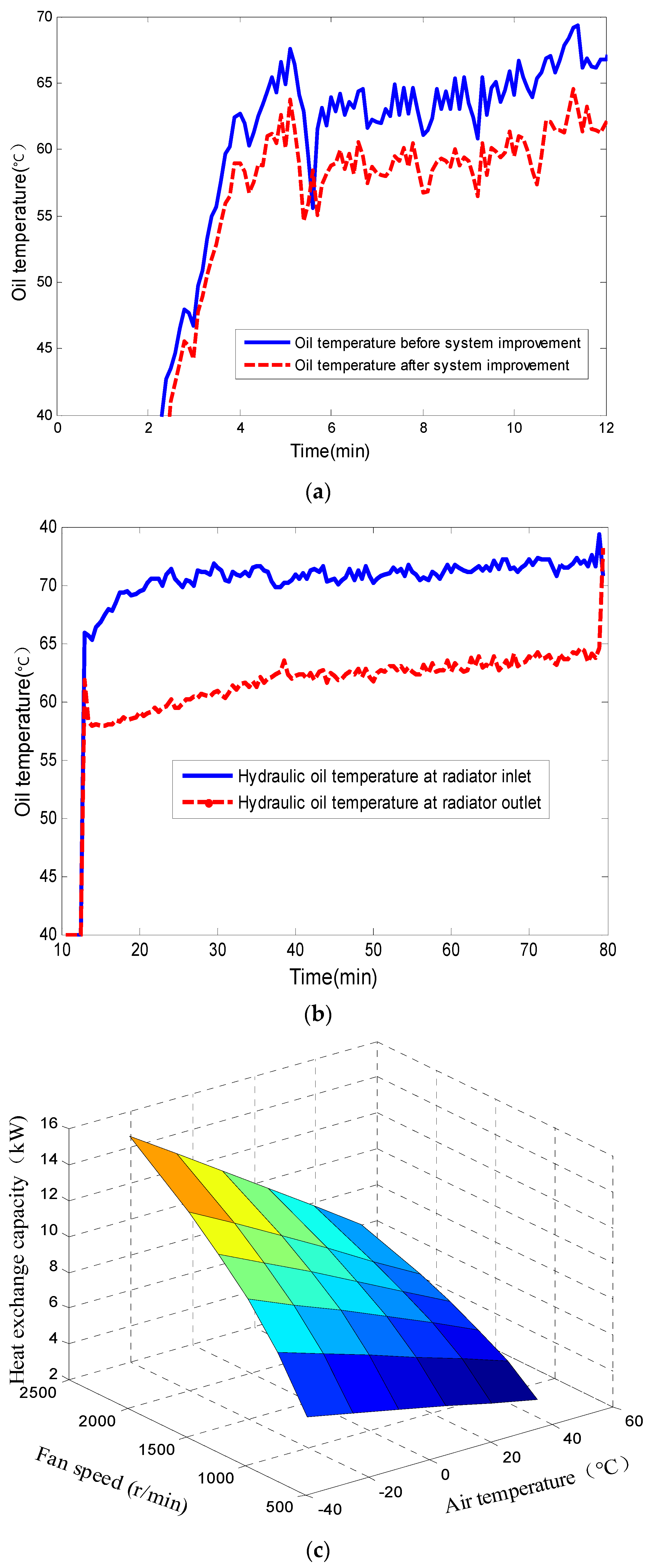
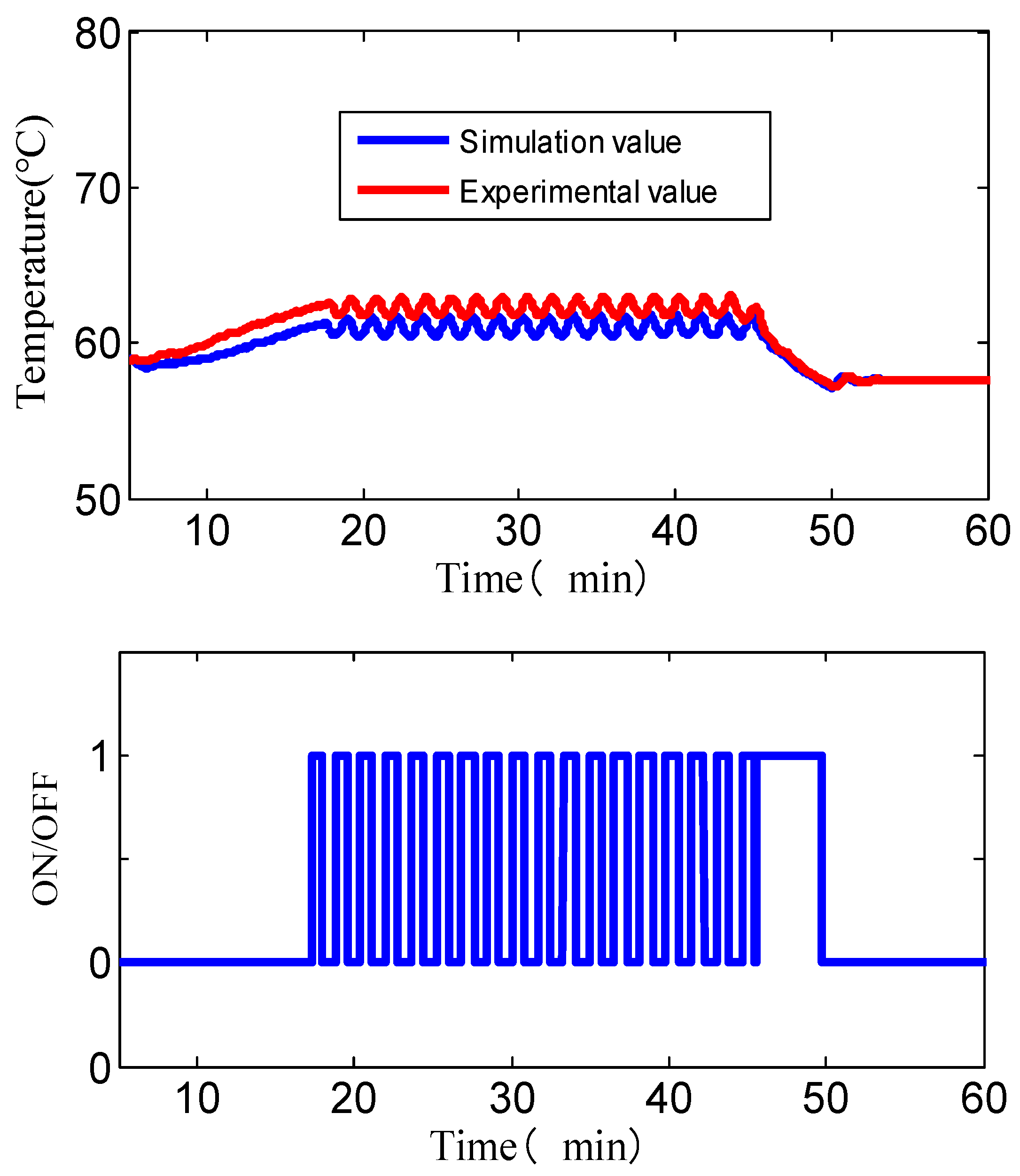
2.4. Cooling System Optimization

According to the thermodynamic models of the above components, the overall thermodynamic simulation model of the hydraulic system is built. The model is mainly composed of drive module, thermal hydraulic module and cooling module. The heat exchange model of the hydraulic system is shown in Figure 4, which consists of a hydraulic pump, a multi-way valve, a hydraulic cylinder, a radiator, and a fan. The air cooling system has the advantages of having simple structure and a light weight, a quick start-up and heating up, being insensitive to heat dissipation capacity and temperature change, and convenient use and maintenance. Therefore, the cooling of the machine tool generally adopts an air cooling system. The heat generated in the system due to pressure loss, mechanical friction, etc., is dissipated to the environment through forced convection heat exchange between the radiator and the air. In addition, some of the heat is dissipated from the pipes and tanks through radiation, convection and conduction. The components of the cooling module include an oil circulation sensor, oil temperature-sensing resistor, oil circulation pump, oil tank, heat exchanger and cooling fan, oil pressure switch and tube state detection circuit board. The circulating pump provides the power to circulate the oil in the oil tank and the heat exchanger pipes, and is responsible for supplying oil to the headstock and drive components. The temperature detection resistor is responsible for detecting the temperature of the oil. As the temperature of the oil in the tank increases, its resistance decreases. The oil temperature error signal is given when the oil reaches the maximum temperature. The system will lock immediately if one of the three signals of oil circulation, oil pressure and oil temperature is wrong.
Considering the influence of the oil temperature rise of the machine tool hydraulic system on the machine tool work, the heat transfer process inside and outside the radiator was analyzed based on the heat exchange principle between oil and air. Then, we found the best outlet oil temperature, and calculated the relationship between the inlet oil temperature of the radiator and the oncoming wind speed. Combined with the logic control of the fan, the cooling system has the advantages of fast action, high efficiency and low energy consumption. Finally, the oil temperature is controlled in the high-efficiency region of its viscosity–temperature performance, so as to ensure the efficient and reliable operation of the machine tool.
First, we calculated the required cooling air flow according to the heat dissipation, and selected the fan model according to the flow and torque, as well as the matching point. When the ambient temperature is 40 °C, the cooling system is designed to have a maximum heat dissipation of 19 kW, and the required cooling air flow is
Q = W Δ t C ρ = 19 30 1.047 1.2 = 0 . 5   ( m 3 / s )
The shaft power calculation formula when a single fan is working is
P = p f Q f η = 600 × 0.25 0.4 = 0 . 375   ( kW )
The torque for a single fan is
T f = 9550 P n = 9550 × 0.375 1800 = 2   ( N m )
The performance curve of the matched fan after calculation is shown in Figure 5. Table 2 lists the physical parameters of the cooling air when the ambient temperature is 23 °C ± 2 °C and the humidity is 45–55%RH.
As a calibration, not only is the fan control logic is required to be normal, but also the relevant control input information is executed accurately and without error. First, you need to set the temperature of the thermostat to 60 °C, as shown in Figure 6. When the temperature of the hydraulic oil entering the cooler is T ≤ 60 °C, the system is in a non-starting state. However, when the inlet oil temperature T > 60 °C entering the cooler, the oil temperature sensor acts on the governor to adjust the air volume of the fan, so as to release the internal heat of the hydraulic oil to the atmosphere in time and quickly.
The hydraulic pump is the power source of the hydraulic system, and its working condition affects the degree of heating of the system. If the matching position between the valve plate in the pump and the cylinder block is greatly worn, it often causes the hydraulic pump to heat up quickly. The working pressure of the hydraulic system depends on the external load, and the relief valve is a device that overflows when the system pressure is higher than the set pressure. When the pressure is high, the leakage in the system increases and the oil temperature rises. If the pressure adjustment of the relief valve is too high or too low, it will also cause the hydraulic system to heat up. If the system pressure is adjusted too high, the hydraulic pump will run under the rated pressure, which will overload the pump and cause the oil temperature to rise; on the contrary, if the system pressure is adjusted and is too low, the working mechanism will frequently open and unload the overflow valve under normal load, causing the hydraulic system to overflow and heat up.
In order to better understand the heat source distribution of each component of the hydraulic system, the comparison of the heat production of the main components under different actions in a cycle when the hydraulic system reaches thermal equilibrium was calculated, as shown in Figure 7. It can be seen from the figure that the heat sources were mainly hydraulic pumps, hydraulic cylinders, hydraulic pipelines, relief valves and reversing valves. Hydraulic pumps and multi-way valves and unloading valves were the main heat-generating elements. Various operating valves generated the most heat, mainly because the frequent opening and reversing of various valves leads to higher overflow losses and generates more heat. The main reason why the working pump generates more heat is that the leakage in the hydraulic pump increases the power loss. The internal wear of the pump is serious, and then heat is generated, so a hydraulic pump with high volumetric efficiency should be selected. In addition, the flow rate of the hydraulic system in the fast running condition was relatively large, and the resistance of the hydraulic pipeline was relatively large. The mechanical loss of the hydraulic cylinder and the pressure loss of the pipeline also generated a certain amount of heat. The heat generated by the mechanical friction inside the hydraulic cylinder in the hydraulic system was mostly absorbed by the hydraulic oil and brought back to the tank, which is another main reason for the increase in oil temperature. The heat production of the hydraulic pump mainly depends on the volumetric efficiency of the pump. Therefore, improving the volumetric efficiency of the hydraulic pump can effectively reduce the heat generation of the hydraulic system, and at the same time has a great impact on the efficiency of the entire hydraulic system.
From the heat dissipation distribution of each part of the system in Figure 8, it can be seen that the heat generated by the hydraulic system is mainly dissipated through the radiator and the oil tank. Among them, the heat dissipation of the radiator is the largest, accounting for about 55% of the total heat dissipation of the system. The heat dissipation of the fuel tank and pipeline accounts for about 14% and 10%, respectively. It can be seen from the simulation results that the heat exchange efficiency of the radiator plays the most important role in the heat balance of the entire hydraulic system. Since there is a dedicated fan to enhance the heat exchange of the cooler, the heat dissipation efficiency is significantly improved. And because the speed of the fan changes with the oil temperature, the oil temperature can be controlled within a small fluctuation range, and the leakage caused by the temperature rise and fall can be reduced, thereby improving the efficiency of the system.
Excessive oil temperature will affect the life of hydraulic system components and the reliability of the system, so necessary measures should be taken to control the temperature of the hydraulic system within a reasonable range. The temperature change of the hydraulic oil in the oil tank before and after the optimization of the cooling system is shown in Figure 9a. When the ambient temperature is 40 °C, the thermal equilibrium temperature of the hydraulic system drops from the original 65 °C to 58 °C, which is lower than the upper limit of 60 °C to meet the heat dissipation requirements. It can be seen from Figure 9b that the heat dissipation efficiency of the radiator after switching to two electronic fans was higher than that of the original air cooling system. Plateau and high temperature environments had little impact on the cooling system, so the improved cooling system could meet the heat dissipation requirements of the machine tool hydraulic system in plateau and high temperature environments. Figure 9c shows the heat transfer performance and influence relationship of the radiator under different parameters, which can provide a reference for the optimization of the control strategy. In actual work, the check valve of the oil return filter element of the hydraulic system is installed at the bottom of the oil return filter element and connected to the radiator in parallel. If the oil is not changed for a long time and it is in disrepair for a long time, the oil will be seriously polluted, causing the valve to be stuck in the normally open position. If this one-way valve fails, the oil will not pass through the radiator, but will flow back to the fuel tank directly. Therefore, the oil return radiator will not have a heat dissipation effect, which will inevitably cause the oil temperature to be too high.
It can be seen from the experimental results in Figure 10 that after the improvement, the heat balance temperature of the hydraulic oil can be well controlled at 60 °C, within the allowable error range (in the case of ensuring a good heat exchange effect, and leaving a margin for the cooler). The experimental results show that the optimal fan speed was 3200 r/min and the flow rate was 0.2 m3/s at 26 °C. The heat dissipation efficiency meets the heat dissipation requirements of the machine tool and is higher than the original air cooling system. Obviously, the fluctuation of temperature is relatively small, within ±1 °C. In addition, after adopting the new control strategy, the distribution of the fan’s working state over time has become significantly more uniform. The system has the advantages of intelligence, sensitive action response, high efficiency and low energy consumption, and adopts air-cooled type, which does not pollute water compared with water-cooled type, and plays a role in energy saving and environmental protection. Moreover, the stability of the machine tool work is improved, thereby greatly improving the work efficiency of the machine tool.

3. Conclusions

The error caused by the thermal expansion of the machine tool is the biggest source of error that affects the stability of the machining accuracy of a machine tool. The temperature of the key point of the machine tool has a nonlinear relationship with the thermal error of the spindle, and has a certain dynamic and periodicity. Therefore, how to establish an effective and accurate model has become a research hotspot. Because the machine tool is subject to many internal heat sources and external heat sources, the heat exchange method cannot be ideally calculated. In addition, there are many parts in contact and the relationship is complex, so it is extremely difficult to qualitatively analyze the position of the main heat source of the machine tool according to the heating principle. Therefore, it is difficult to establish an accurate temperature field and thermal deformation model by the general finite element method. In this paper, a one-dimensional dynamics and thermodynamic simulation model of a certain machine tool hydraulic system was established, and the existing hydraulic system was optimized. The coupled simulation method was used to analyze the heat generation characteristics of the heat generation distribution of different components of the hydraulic system. The heat dissipation path of the hydraulic system and the heat balance characteristics of the cooling system in the extreme high temperature environment were, further, obtained. The experimental results showed that the optimal fan speed was 3200 r/min and the flow rate was 0.2 m3/s at 26 °C. The thermal balance temperature of the hydraulic system was reduced from the original 65 °C to 58 °C, and its cooling capacity met the requirements of high altitude and high temperature environment.

Author Contributions

Conceptualization, Q.Z. and X.L.; methodology, X.L.; software, Z.C.; validation, Z.T., Q.Z. and X.L.; formal analysis, Z.C.; investigation, X.L.; resources, X.L.; data curation, Q.Z.; writing—original draft preparation, Q.Z.; writing—review and editing, X.L.; visualization, Z.T.; supervision, X.L.; project administration, Q.Z.; funding acquisition, X.L. All authors have read and agreed to the published version of the manuscript.

Funding

This research was funded by [National Natural Science Foundation of China], grant number [52105280]; Zhejiang Provincial Natural Science Foundation of China, grant number [LQ21E060009]; Natural Science Foundation of Zhejiang Province, grant number [LZ22E050008]; Natural Science Foundation of Ningbo, grant number [2021J150]; Science and Technology Major Project of Ningbo, grant number [2021Z110]; and the APC was funded by [Science and Technology Major Project of Ningbo].

Acknowledgments

The authors would like to thank the reviewers for their helpful suggestions.

Conflicts of Interest

The authors declare that they have no known competing financial interests or personal relationships that could have appeared to influence the work reported in this paper.

Nomenclature

   Symbols   ld  Length of damping hole [m]
   A  Heat transfer area [m2]   Pin  Inlet pressure [Pa]
   Cp  Specific heat capacity [J/kg.K]   Pout  Outlet pressure [Pa]
   W  Thermal power[kW]   Fd  Output force [N]
   Qf  Volume flow [m3·s−1]   A1  Cross-sectional area [m2]
   Δ t   Temperature difference [°C]   A2  Cross-sectional area [m2]
   P  Fan drive power [kW]   Abbreviation
   Tf  Fan torque [N·m]  min  Minimum value
   U  Heat transfer coefficient [J kg−1K−1]  max  Maximum value
   m ˙   Mass flow rate [kg s−1]  NTU  Number of heat transfer units
   n  Percentage of heat in the fuel heat  exp  Exponential
   g  fuel consumption rate [g/kW·h]   Superscripts and subscripts
   N  Calibrated power of the engine   Out  Outlet
   h  Low calorific value of fuel   In  Inlet
   Vm  Flow rate of motor [mL·r−1]   m  Motor
   Pp  Pump power [kW]   p  Pump
   qp  Pump flow rate [mL·r−1]   f  Fan
   np  Pump speed [r·min−1]   p  Pressure
   P1  pressure of the main valve cavity   h  Hot
   P2  Pressure of the pilot valve cavity [N]   c  Cool
   Fs  Steady-state hydrodynamic force [N]   V  Valve
   kD1  current-force gain factor   s  Steady-state
   i   Current [A]   d  Damping hole
   k1  Current-force gain   Greek Symbols
   k2  Displacement-force gain   η   Transmission efficiency
   y   Displacement [m]   ε   Emissivity
   x  Displacement of valve spool [m]   φ   Spool half-cone angle [°]
   dd  Diameter of damping hole [m]   ρ   Density [kg·m−3]
   Ad  Flow area [m2]   ν   Viscosity (m2/s)

References

  1. Tong, Z.; Miao, J.; Li, Y.; Tong, S.-G.; Zhang, Q.; Tan, G.-R. Development of electric construction machinery in China: A review of key technologies and future directions. J. Zhejiang Univ.-Sci. A 2021, 22, 245–264. [Google Scholar] [CrossRef]
  2. Xie, Y.; Liu, Z.; Li, K.; Liu, J.; Zhang, Y.; Dan, D.; Wu, C.; Wang, P.; Wang, X. An improved intelligent model predictive controller for cooling system of electric vehicle. Appl. Therm. Eng. 2021, 182, 116084. [Google Scholar] [CrossRef]
  3. Fan, R.; Zheng, N.; Sun, Z. Evaluation of fin intensified phase change material systems for thermal management of Li-ion battery modules. Int. J. Heat Mass Transf. 2021, 166, 120753. [Google Scholar] [CrossRef]
  4. Wang, S.; Ji, S.; Zhu, Y. A comparative study of cooling schemes for laminated lithium-ion batteries. Appl. Therm. Eng. 2021, 182, 116040. [Google Scholar] [CrossRef]
  5. Yang, W.; Zhou, F.; Liu, Y.; Xu, S.; Chen, X. Thermal performance of honeycomb-like battery thermal management system with bionic liquid mini-channel and phase change materials for cylindrical lithium-ion battery. Appl. Therm. Eng. 2021, 188, 116649. [Google Scholar] [CrossRef]
  6. Akbarzadeh, M.; Jaguemont, J.; Kalogiannis, T.; Karimi, D.; He, J.; Jin, L.; Xie, P.; Van Mierlo, J.; Berecibar, M. A novel liquid cooling plate concept for thermal management of lithium-ion batteries in electric vehicles. Energy Convers. Manag. 2021, 231, 113862. [Google Scholar] [CrossRef]
  7. Xu, Y.; Li, X.; Liu, X.; Wang, Y.; Wu, X.; Zhou, D. Experiment investigation on a novel composite silica gel plate coupled with liquid-cooling system for square battery thermal management. Appl. Therm. Eng. 2021, 184, 116217. [Google Scholar] [CrossRef]
  8. Samudre, P.; Kailas, S.V. Thermal performance enhancement in open-pore metal foam and foam-fin heat sinks for electronics cooling. Appl. Therm. Eng. 2022, 205, 117885. [Google Scholar] [CrossRef]
  9. Jin, Q.; Wen, J.T.; Narayan, S. Oscillatory valve effect on temperature synchronization in microchannel cooling systems. Appl. Therm. Eng. 2022, 204, 117999. [Google Scholar] [CrossRef]
  10. Guo, Z.M.; Pfotenhauer, J.M.; Miller, F.K.; Zhu, S.W. A research of micro-pulse tube cryocooler with displacer phase shifter. Appl. Therm. Eng. 2022, 205, 117995. [Google Scholar] [CrossRef]
  11. Alzahrani, S.; Islam, M.S.; Sah, S.C. Heat transfer enhancement of modified flat plate heat exchanger. Appl. Therm. Eng. 2021, 186, 116533. [Google Scholar] [CrossRef]
  12. Al-Turki, Y.A.; Mori, H.; Shawabkeh, A. Thermal, frictional and exergetic analysis of non-parallel configurations for plate heat exchangers. Chem. Eng. Process. Process Intensif. 2021, 161, 108319. [Google Scholar] [CrossRef]
  13. Arsenyeva, O.; Tran, J.; Piper, M.; Kenig, E. An approach for pillow plate heat exchangers design for single-phase applications. Appl. Therm. Eng. 2019, 147, 579–591. [Google Scholar] [CrossRef]
  14. Khalil, I.; Hayes, R.; Pratt, Q.; Spitler, C.; Codd, D. Experimental and numerical modeling of heat transfer in directed thermoplates. Int. J. Heat Mass Transf. 2018, 123, 89–96. [Google Scholar] [CrossRef]
  15. Feng, S.Z.; Cheng, Y.H. An element decomposition method for heat transfer analysis. Int. J. Heat Mass Transf. 2018, 123, 437–444. [Google Scholar] [CrossRef]
  16. Mayo, I.; Arts, T.; Gicquel, L.Y.M. The three-dimensional flow field and heat transfer in a rib-roughened channel at large rotation numbers. Int. J. Heat Mass Transf. 2018, 123, 848–866. [Google Scholar] [CrossRef]
  17. Gong, C.; Du, Y.; Yu, Y.; Chang, H.; Luo, X.; Tu, Z. Numerical and experimental investigation of enhanced heat transfer radiator through air deflection used in fuel cell vehicles. Int. J. Heat Mass Transf. 2022, 183, 122205. [Google Scholar] [CrossRef]
  18. Zhang, B.; Qu, Z.; Guo, T.; Sheng, M.; Chen, M. Coupled thermal-hydraulic investigation on the heat extraction performance considering a fractal-like tree fracture network in a multilateral well enhanced geothermal system. Appl. Therm. Eng. 2022, 208, 118221. [Google Scholar] [CrossRef]
  19. Lu, Q.; Yuan, Y.; Li, F.; Yang, B.; Li, Z. Prediction method for thermal-hydraulic parameters of nuclear reactor system based on deep learning algorithm. Appl. Therm. Eng. 2021, 196, 117272. [Google Scholar] [CrossRef]
  20. Xie, Y.; Guo, H.; Li, W.; Zhang, Y.; Chen, B.; Zhang, K. Improving battery thermal behavior and consistency by optimizing structure and working parameter. Appl. Therm. Eng. 2021, 196, 117281. [Google Scholar] [CrossRef]
  21. Xu, X.; Zhang, X.; Xiao, Y. Research on influence of high and low temperature heat sources for heat transfer characteristics of pulsating heat pipe cold storage device. Heat Mass Transf. 2022, 58, 233–246. [Google Scholar] [CrossRef]
  22. Zheng, S.; Feng, Z.; Lin, Q.; Hu, Z.; Lan, Y.; Guo, F.; Huang, K. Numerical investigation on thermal–hydraulic characteristics in a mini-channel with trapezoidal cross-section longitudinal vortex generators. Appl. Therm. Eng. 2021, 199, 117542. [Google Scholar] [CrossRef]
  23. Chen, S.R.; Lin, W.C.; Ferng, Y.M.; Chieng, C.C.; Pei, B.S. CFD simulating the transient thermal–hydraulic characteristics in a 17 × 17 bundle for a spent fuel pool under the loss of external cooling system accident. Ann. Nucl. Energy 2014, 73, 241–249. [Google Scholar] [CrossRef]
  24. Zhou, Y.; Yin, D.; Guo, X.; Dong, C. Numerical analysis of the thermal and hydraulic characteristics of CO2/propane mixtures in printed circuit heat exchangers. Int. J. Heat Mass Transf. 2022, 185, 122434. [Google Scholar] [CrossRef]
  25. Kwon, H.; Ivantysynova, M. Experimental and theoretical studies on energy characteristics of hydraulic hybrids for thermal management. Energy 2021, 223, 120033. [Google Scholar] [CrossRef]
  26. Hui, K.; Chen, W.; Li, S.; Zhao, Q.; Yan, J. Experimental study on transient thermal–hydraulic characteristics of an open natural circulation for the passive containment cooling system. Int. J. Heat Mass Transf. 2021, 179, 121680. [Google Scholar] [CrossRef]
  27. Kaood, A.; Hassan, M.A. Thermo-hydraulic performance of nanofluids flow in various internally corrugated tubes. Chem. Eng. Process. Process Intensif. 2020, 154, 108043. [Google Scholar] [CrossRef]
  28. Khalil, E.E.; Kaood, A. Numerical Investigation of Thermal-Hydraulic Characteristics for Turbulent Nanofluid Flow in Various Conical Double Pipe Heat Exchangers. In Proceedings of the AIAA Scitech 2021 Forum, Virtual, 11–15 & 19–21 January 2021. [Google Scholar]
  29. Sun, P.; Li, Q.; He, H.; Chen, H.; Zhang, J.; Li, H.; Liu, D. Design and optimization investigation on hydraulic transmission and energy storage system for a floating-array-buoys wave energy converter. Energy Convers. Manag. 2021, 235, 113998. [Google Scholar] [CrossRef]
  30. Tan, K.; Hu, Y.; He, Y. Effect of wettability on flow boiling heat transfer in a microtube. Case Stud. Therm. Eng. 2021, 26, 101108. [Google Scholar] [CrossRef]
  31. Yao, P.; Zhai, Y.; Li, Z.; Shen, X.; Wang, H. Thermal performance analysis of multi-objective optimized microchannels with triangular cavity and rib based on field synergy principle. Case Stud. Therm. Eng. 2021, 5, 100963. [Google Scholar]
Figure 1. Research object: (a) drive-system hydraulic station; (b) radiator-performance test device.
Energies 16 07322 g001
Figure 2. Simulation model of hydraulic system of the machine tool.
Energies 16 07322 g002
Figure 3. Simulation results of dynamic characteristics of hydraulic system. (a) Pressure-change curve of hydraulic system. (b) Flow-change curve of hydraulic system.
Energies 16 07322 g003aEnergies 16 07322 g003b
Figure 4. Simulation model of machine tool thermo-hydraulic system.
Energies 16 07322 g004
Figure 5. Cooling fan characteristic curves. (a) Static pressure–air volume characteristic curve. (b) Shaft power–air volume characteristic curve.
Energies 16 07322 g005
Figure 6. Control logic of cooling system fan.
Energies 16 07322 g006
Figure 7. Distribution of heat production in hydraulic system.
Energies 16 07322 g007
Figure 8. Distribution of heat dissipation in the hydraulic system.
Energies 16 07322 g008
Figure 9. Simulation results of heat dissipation performance of cooling system. (a) Oil temperature comparison in fuel tank. (b) Hydraulic oil temperature at radiator inlet and outlet. (c) Heat transfer relationship of radiator under different parameters.
Energies 16 07322 g009
Figure 10. Experimental results of the improved system and the fan switch status.
Energies 16 07322 g010
Table 1. Thermophysical properties of hydraulic oil.
ParameterRelational Formula
Density (kg/m3) ρ = 959.7 1 + 60.4 × 10 5 T 20
Specific heat capacity (kJ/kg °C) C p = 0.0028 T 100 + 2.06 × 10 3
Dynamic viscosity (Pa·s) ν = 5 3 × 10 10 10.25467 / T 3.69731 0.6
Thermal conductivity (kW/m °C) λ = 0.1225 1 0.00054 T
Table 2. Thermophysical properties of cooling air.
ParameterRelational Formula
Density (kg/m3) ρ c = 1.2916 4.5037 × 10 3 T + 1.0583 × 10 5 T 2
Specific heat capacity (kJ/kg °C) C p c = 1.003 + 0.02 T + 0.0004 T 2
Dynamic viscosity (Pa·s) η c = 17.1315 + 5.072 × 10 2 T 2.4473 × 10 5 T 2
Thermal conductivity (kW/m °C) λ c = 55.1329 + 0.2563 T 1.2599 × 10 3 T 2
Disclaimer/Publisher’s Note: The statements, opinions and data contained in all publications are solely those of the individual author(s) and contributor(s) and not of MDPI and/or the editor(s). MDPI and/or the editor(s) disclaim responsibility for any injury to people or property resulting from any ideas, methods, instructions or products referred to in the content.

