Article

Battery Energy Storage System Damper Design for a Microgrid with Wind Generators Participating in Frequency Regulation

Department of Electrical Engineering, National Taiwan University, Taipei 10617, Taiwan
*
Author to whom correspondence should be addressed.
Energies 2023, 16(21), 7439; https://doi.org/10.3390/en16217439
Submission received: 4 October 2023 / Revised: 29 October 2023 / Accepted: 1 November 2023 / Published: 3 November 2023

Abstract

:
Ancillary frequency control schemes (e.g., droop control) are used in wind farms to improve frequency regulation in grids with substantial renewable energy penetration; however, droop controllers can have negative impacts on the damping of wind turbine torsional mode, thereby reducing the lifespan of the turbine gearbox. This paper presents a battery energy storage system (BESS) damper to improve the damping of torsional vibrations when using doubly fed induction generators (DFIGs) for frequency regulation in a microgrid. We formulated a linearized model comprising diesel generators, a wind turbine with five-mass drivetrain, and BESS. We also designed a feedforward compensator to deal with phase lag between the BESS damper signal and DFIG torque. The proposed BESS damper was shown to improve the torsional mode damping by moving the eigenvalues for torsional mode leftward to desirable locations on the complex plane. Dynamic simulations performed using MATLAB/SIMULINK demonstrated the efficacy of the proposed BESS torsional mode damping scheme in terms of torsional mode 1 damping performance and frequency response.

1. Introduction

1.1. Background and Literature Review

Ancillary frequency control systems (e.g., droop control) are commonly used in wind farms to enhance the stability of grids with high renewable energy penetration. Unfortunately, droop controllers can have an adverse effect on wind turbine torsional mode [1]. In an effort to improve torsional mode damping, researchers have designed resonance dampers for the rotor-side converters used in wind generators [1,2,3].
Ancillary frequency control in wind generation systems is generally performed using droop controllers or inertial controllers [4]. The former generates a supplementary frequency regulation signal proportional to deviations in system frequency, whereas the latter generates a frequency regulation signal proportional to the rate at which the system frequency changes. In this paper, we will focus on droop controllers, since it was pointed out in [5] that the optimal inertia gain with the highest frequency nadir was close to zero. Droop gain must be selected carefully to ensure that the frequency nadir can be improved without imposing wind generator stalls or secondary frequency dips, due to a drop in the kinetic energy of the generator. In [6], a dynamic droop controller based on the rate of frequency change was proposed. In [7], droop gain was adjusted according to generator speed. Lee et al. [8] proposed an approach in which droop gain was varied according to the kinetic energy of the wind generator. Researchers have recently developed dynamic droop control methods based on fuzzy logic [9,10]. In [11], a frequency control strategy based on coordinated robust dynamic droop power sharing was proposed for an islanded wind-powered microgrid. Researchers have recently developed piecewise linear time-variable droop functions [12,13]. Kumar [14] proposed a coordinated droop and inertia control strategy for de-loaded offshore renewable power generators with HVDC-link. The impact of primary and secondary frequency control on the frequency variations caused by wind variability was investigated in [15]. In [16], the authors presented a novel frequency control approach that associates the grid-side converter (GSC) with a synchronverter and a BESS. A critical review of synchronverter technology which could increase the inertial response of renewable energy sources (RESs) was presented in [17].
Subsynchronous oscillations have attracted considerable attention for wind generators connected to a weak grid using series capacitors for compensation [18]. In [19], the induction generator effect and sub-synchronous control interaction were discussed for two different types of wind turbines: a doubly fed induction generator and a permanent magnet synchronous generator. In [20], the authors presented a novel approach to analyzing damping torque to detect and assess the risk of open-loop modal resonance exciting torsional sub-synchronous oscillations. Li et al. [21] proposed a high-pass filter with a proportional controller to mitigate subsynchronous oscillations. In [22], the authors developed a method that uses a bandpass filter and lead-lag compensator to improve the damping of subsynchronous oscillations. In [23,24], a compensation filter with damping terms was added to the rotor-side converter to mitigate subsynchronous oscillations. Researchers in [25] proposed a nonlinear sliding mode damping controller for subsynchronous oscillations. Two control laws based on stator voltage and current were developed in [26] to regulate active and reactive power with the aim of improving transient response damping. A linear quadratic regulator was proposed in [27] for the damping of subsynchronous interactions in doubly-fed induction generator-based wind farms. Ghaffarzdeh et al. [28] proposed an adaptive supplementary controller based on the multiple-model adaptive control approach to mitigate subsynchronous resonance induced by a type III wind system. Ali et al. [29] investigated sub-synchronous control interactions in doubly-fed induction generators based on eigenvalue analysis. In [30], the authors investigated the impact of wind park operating conditions and DFIG control system parameters on subsynchronous control interactions.
It has recently been reported that ancillary droop controllers can excite torsional vibrations in wind turbines [1]. Most ancillary droop controllers take frequency deviation as the input and transmit an output signal to adjust torque commands for the rotor-side converter (RSC) of the DFIG. This implies that oscillations in system frequency imposed by load variations can excite DFIG torsional oscillations via the RSC torque command. In [1], researchers used Bode plots to design a torsional oscillation damper using a two-mass drivetrain model for wind turbines. Mandic et al. [2] designed three bandpass dampers for three torsional modes based on a five-mass drivetrain model. Note, however, that they did not account for the effect of droop control on torsional modes. In [3], researchers developed a sliding mode controller to enhance torsional mode damping. Licari et al. [31] proposed a model-based torsional damper using a Kalman filter.

1.2. Research Gap and Motivation

The damping signals used to control the torsional oscillations or subsynchronous oscillations of the DFIG are generally added to the rotor-side converter [1,2,3,23,24,25,26,27,32], grid-side converter [21], or both [27]. There has been relatively little research on the design of dampers on the battery energy storage systems (BESSs).
The ever-increasing penetration of renewable energy into power systems has prompted considerable interest in the use of BESSs for frequency regulation. Teleke et al. [32] developed a model predictive control (MPC) technique based on receding horizon control to manage BESS power in accordance with forecasted wind conditions. Researchers have also developed a fuzzy-logic based frequency controller for wind farms that use a BESS [33]. These methods have made it possible to minimize BESS capacity while largely eliminating the need for inflexible wind energy de-loading. Wu et al. [34] constructed a small-scale BESS to avoid the secondary frequency drops during rotor-speed recovery. Researchers have also proposed a proportional integral (PI)-lead and lead-lag controlled BESS to enable frequency, as well as voltage regulation for multimachine power systems [35]. Choi et al. [36] proposed a frequency regulation scheme that uses a hybrid strategy involving wind generator kinetic energy control and BESS output power control. In [37], researchers developed a fuzzy-based wind–hybrid energy storage system to reduce frequency variations caused by fluctuations in wind power. In [38], researchers developed an artificial neural network (ANN) controller to regulate the power flow between wind generators and the grid. Shim et al. [39] proposed a droop control and state of charge (SoC) feedback (DaSOF) scheme for BESSs which aimed to improve frequency regulation. Zhao et al. [40] recently constructed a frequency-domain model to enable the pole-based dynamic analysis of control interactions between grid-forming BESSs and offshore wind power plants.
Researchers have also created control systems to regulate the power flow in and out of the BESS with the aim of enhancing the stability of wind–diesel power systems integrated with a BESS [41]. Daraiseh [42] assessed the ability of energy storage systems to prevent frequency instabilities while providing a primary frequency response. In [43], Gu et al. developed a mathematical model for a vanadium redox flow battery (VRFB), as well as a scheme by which to smooth fluctuations in wind power. Researchers in [44] evaluated the benefits of demand response control and battery energy storage on frequency regulation in a power system integrated with a wind farm. In [45], researchers proposed a novel control strategy for a hybrid energy storage system comprising a BESS and a supercapacitor energy storage system (SCESS). Their system diverts the low-frequency components of power imbalance to the BESS, while the high-frequency components are diverted to SCESS. Parthasarathy et al. [46] recently proposed a detailed lithium ion battery model for the design of BESS controllers for active network management. In [47], researchers utilized a model predictive controller to enhance the dynamic performance of a system comprising a wind-driven synchronous generator, a fuel cell, and a BESS. In [48], a novel concept of a Smart Battery that brings together batteries with advanced power electronics and artificial intelligence (AI) was proposed for battery lifetime improvement. In [49], researchers reviewed the existing methods of increasing the energy efficiency of electric transport by analyzing and studying the methods of increasing energy storage capacities. In [50], researchers introduced the wear density function to provide a precise lifespan prediction of BESS. Furthermore, a quantitative tradeoff relationship between frequency regulation performance and battery lifecycle was derived using operational data of the actual BESS for frequency regulation. In [51], a frequency control method, in which battery energy storage systems (BESSs) participate in automatic frequency restoration reserve (aFRR) provision through their integration in the AGC of an island system, was presented. In [52], a BESS model with variable efficiency was used to compare the provision of Frequency Containment Reserve (FCR) with different SoC restoration strategies.
In view of widespread use of BESSs in a system with a high penetration of wind generators, we propose a design for a torsional damper on the BESS in this paper.

1.3. Contributions

The main contributions of this paper are as follows:
(1)
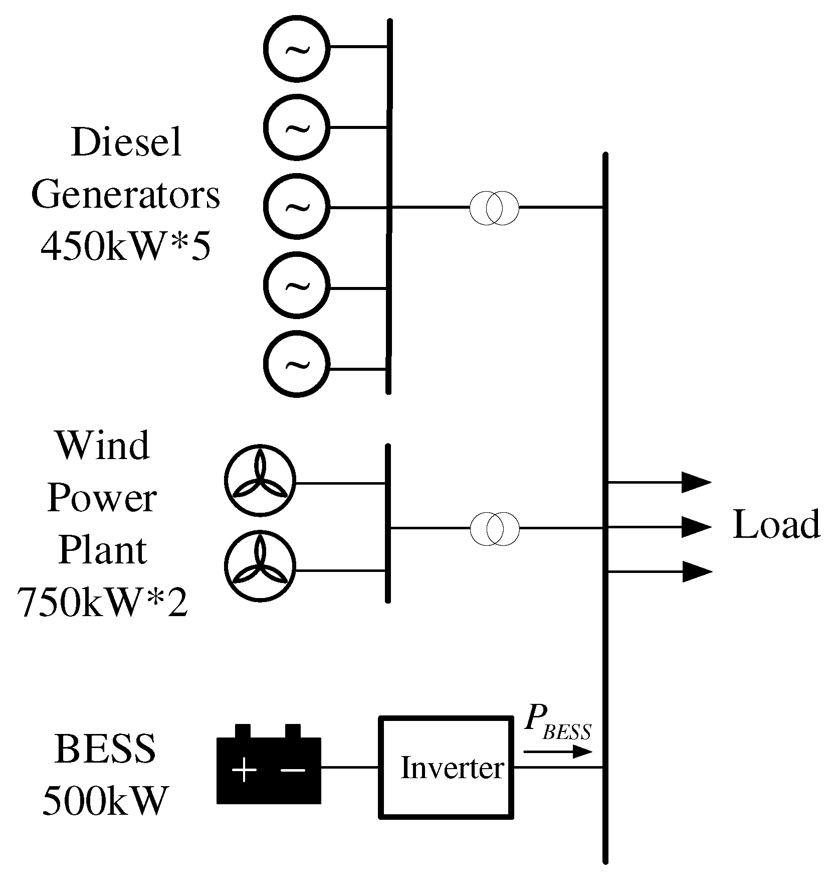
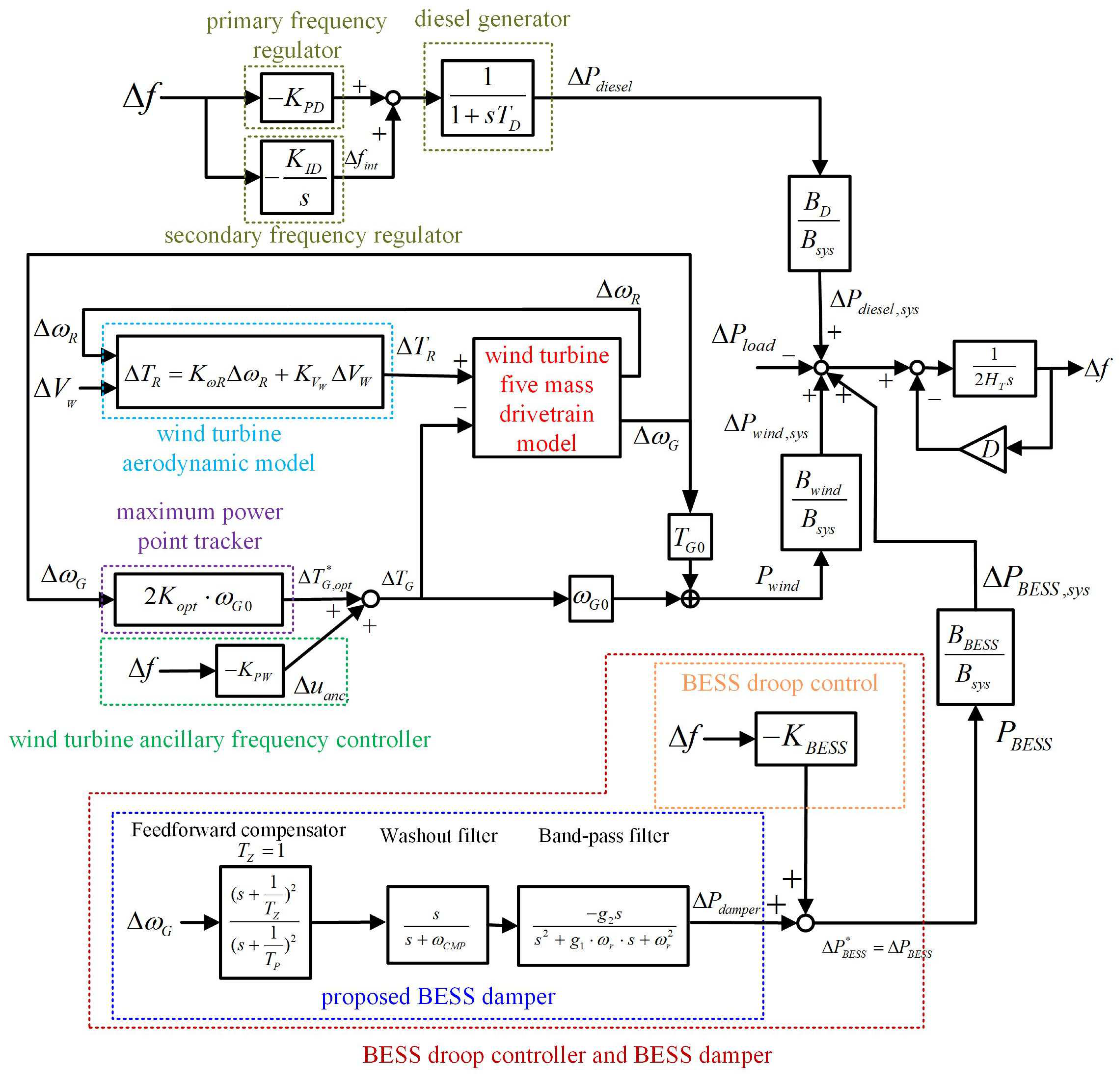
We present a complete model for a microgrid comprising diesel generators, wind generators with droop control, and a BESS.
(2)
We derived a transfer function that relates the BESS damping signal to the DFIG damping torque. We also designed a feedforward compensator for the BESS damper based on the phase lag computed using the transfer function.
(3)
To improve the damping ratio for the torsional mode, we use the pole assignment method to shift the eigenvalues of poorly damped modes leftward to desired locations. The eigenvalue location with minimal damper gain is chosen in order to minimize power output from the BESS.

1.4. Structure of Paper

The remainder of the paper is organized as follows. Section 2 outlines the proposed microgrid with diesel generators, wind generators, and a BESS. A block diagram of the linearized model is also presented. Section 3 presents the eigenvalues, oscillation frequencies, and damping ratios computed for the microgrid in torsional and frequency modes with and without a BESS. Section 4 presents the BESS damper we developed to compensate for the poor damping ratio in torsional mode 1, which is the primary concern in this work. We first derived the transfer function from BESS damper signals to DFIG torque commands for use in developing a feedforward compensator to deal with the phase lag between the BESS damper signal and DFIG torque command. The constants for the BESS damper are determined using the pole assignment method. Section 5 presents MATLAB/SIMULINK simulation results indicating the effectiveness of the proposed BESS damper.

2. System Model

Figure 1 presents a one-line diagram of microgrid with the BESS examined in this study.
As shown in Figure 1, the proposed microgrid comprises five diesel generators (each unit rated at 450 kW), two wind generators (each unit rated at 750 kW), and a BESS (rated at 500 kW). Figure 2 presents the linearized model for the frequency control of the microgrid using the parameters outlined in the Appendix A.
As shown in Figure 2, the diesel generator is equipped with a proportional controller - K PD Δ f = 1 R D Δ f (droop controller) for primary frequency regulation and an integral controller K ID s Δ f for secondary frequency regulation.
The wind turbine generator is the five-mass drivetrain model described in [2,3]. The mechanical torque from the wind turbine is obtained using the method outlined in [53], as follows:
T R = 1 2 ρ A C P ( λ i , β ) V W 3 ω R
where ρ is the air density, A indicates the area swept by the blades, V W is wind velocity, ω R is the turbine speed, and C P is the power coefficient of the turbine, which can be written as follows:
C P ( λ i , β ) = 0.22 ( 116 λ i 0.4 β 5 ) e 12.5 / λ i
1 λ i = 1 λ T S R + 0.08 β 0.035 β 3 + 1
The tip speed ratio λ TSR is defined as
λ T S R = ω R R R V W
where R R indicates the blade radius.
Incremental mechanical torque, Δ T R , in the linearized model (Figure 2) can be derived as follows:
Δ T R ( s ) = T R ω R Δ ω R ( s ) + T R V W Δ V W ( s ) = K m R Δ ω R ( s ) + K V W Δ V W ( s )
where
K m R = 1 2 ρ A ( ω R 0 C P λ T S R λ T S R ω R C P 0 ) V W 0 3 ω R 0 2
K V W = 1 2 ρ A ( C P λ T S R λ T S R V W V W 0 3 + 3 V W 0 2 C P 0 ) ω R 0
C P λ T S R = C P 1 λ i 1 λ i λ T S R = 0.22 ( 116 e 12.5 λ i 0 12.5 ( 116 λ i 0 0.4 β 0 5 ) e 12.5 λ i 0 ) 1 ( λ T S R 0 + 0.08 β 0 ) 2 = 0.22 116 ( λ T S R 0 + 0.08 β 0 ) 2 + 12.5 ( λ T S R 0 + 0.08 β 0 ) 2 ( 116 λ i 0 0.4 β 0 5 ) e 12.5 λ i 0
λ T S R 0 = ω R 0 R R V W 0
λ T S R ω R = R R V W 0
λ T S R V W = ω R 0 R R V W 0 2
In maximum power point tracking (MPPT) mode, the maximum power generated by the wind turbine generator P wind ,   opt is related to generator speed ω G in accordance with the following expression:
P w i n d , o p t = K o p t ω G 3
where K opt is a constant. This means that the electromagnetic torque of the wind generator under MPPT operation, T G ,   opt * , must be set as follows:
T G , o p t * = K o p t ω G 2
Incremental electromechanical torque ( Δ T G ,   opt * ) in the linearized model (Figure 2) can be derived as follows:
T G , o p t * = 2 K o p t ω G 0 Δ ω G
As shown in Figure 2, when the wind turbine generator participates in frequency regulation, an ancillary control signal, Δ u anc , is added to Δ T G ,   opt * to obtain the desired electromagnetic torque command for the wind generator, Δ T G * , as follows:
Δ T G * = 2 K o p t ω G 0 Δ ω G + Δ u a n c . = 2 K o p t ω G 0 Δ ω G K P W Δ f
where K PW is the droop gain of the wind generator. The time constants for the current regulator are far smaller than the wind generator inertia constant H G ; therefore, we assume that the actual electromagnetic torque Δ T G is assumed to be equal to the torque command Δ T G * in (15).
As indicated by the block diagram of the proposed BESS droop controller and BESS damper (Figure 2), the BESS real power command, Δ P BESS * , is obtained as follows:
Δ P B E S S * = Δ P d a m p e r + ( K B E S S Δ f )
where Δ P damper is the damper power and - K BESS Δ f is the power from the BESS droop controller. Details pertaining to the design of the proposed BESS damper are discussed in Section 4.
Figure 3 presents the equivalent circuit of the battery [32] and a block diagram of the real and reactive power controllers and d-axis and q-axis current regulators of the BESS [33].
The time constants of the BESS equivalent circuit and associated power controllers and current regulators are far smaller than system inertia constant H T ; therefore, the time delay between BESS real power command P BESS * and its actual real power output P BESS is negligible. Thus, we can assume that Δ P BESS * in Figure 2 is equal to Δ P BESS .
Figure 2 also shows that system frequency Δ f is governed by the swing equation of the diesel generators [54,55], as follows:
d Δ f d t = ( Δ P d i e s e l , s y s + Δ P w i n d , s y s + Δ P B E S S , s y s Δ P l o a d ) 2 H T D Δ f 2 H T

3. Modal Analysis of Microgrid with Wind Generator and BESS

The state equation for the linear system in Figure 2 can be written as follows:
Δ X · ( t ) = A Δ X ( t ) + Γ Δ d ( t )
where X = [ Δ f   Δ P diesel   Δ f int   Δ θ R   Δ θ 1   Δ θ 2   Δ θ 3   Δ θ G   Δ ω R     Δ ω 1     Δ ω 2     Δ ω 3     Δ ω G   Δ P damper   Δ P damper 1   Δ P damper 2   Δ P damper 3   Δ P damper 4 ]T is the state vector and Δ d = [ Δ P load   Δ V W ]T is the disturbance vector. Note that Δ P damper , Δ P damper 1 , Δ P damper 2 , Δ P damper 3 , and Δ P damper 4 are the state variables for the BESS damper. The system eigenvalues are computed as the solution to the following equation:
det ( s I A ) = 0

3.1. Modal Analysis of Microgrid without BESS

Table 1 lists the eigenvalues for a system without BESS under wind speed of 11 m/s based on the system parameters listed in the Appendix A. Note that only the eigenvalues for the frequency mode and torsional modes 0, 1, 2, 3, and 4 are of major concern in the design of BESS dampers.
Table 1 lists the values for one frequency mode and five torsional modes, identified as 0, 1, 2, 3, 4. Mode 0 refers to a mode without shaft twist characterized by a real eigenvalue. Mode 1 is of particular concern in this work due to the fact that the damping ratio for this mode is poor (0.0319) and the other three modes (modes 2, 3, and 4) can only be excited by wind fluctuations at the frequency specific to that mode [2]. By contrast, mode 1 can be excited by a step load disturbance causing a frequency mode oscillation at 0.668 Hz, which is very close to that of mode 1 (2.921 Hz), when DFIG participates in ancillary frequency control.

3.2. Modal Analysis of Microgrid with BESS but without BESS Damper

Table 2 and Table 3 list the eigenvalues, frequencies, and damping ratios, respectively, for torsional mode 1 and frequency mode in a microgrid with BESS but without a BESS damper.
As shown in Table 2, the BESS had an insignificant impact on the eigenvalue, frequency, and damping ratio of torsional mode 1. As shown in Table 3, increasing the droop gain for the BESS increased the frequency mode damping ratio and decreased the frequency. Based on the fact that the damping ratio in torsional mode 1 was poor (0.031 for K BESS = 20 ) while the damping ratio in frequency mode was satisfactory (0.751 for K BESS = 20 ), we developed a BESS damper to improve the damping ratio for torsional mode 1.

4. BESS Damper Design Based on Modal Control Theory

In the current study, we designed a BESS damper to improve the damping ratio for torsional mode 1. The block diagram in Figure 4 (derived from Figure 2) illustrates how the proposed BESS damper provides damping torque Δ T G that is in-phase with the speed of the generator Δ ω G . As shown in Figure 2 and Figure 4, the BESS damper generates a damping signal Δ P damper with Δ ω G as its input. The transfer function of the proposed BESS damper is as follows:
H d a m p e r ( s ) = ( s + 1 T Z ) 2 ( s + 1 T P ) 2 s s + ω C M P g 2 s s 2 + g 1 ω r s + ω r 2 = H 1 ( s ) H 2 ( s ) H 3 ( s )
Note that the transfer function in (20) comprises H 1 ( s ) for a feedforward compensator, H 2 ( s ) for a washout filter (high-pass filter), and H 3 ( s ) for a bandpass filter. Details pertaining to the design of the feedforward compensator and bandpass filter are presented in Section 4.1 and Section 4.2.
The output from the BESS, Δ P damper , is multiplied by a base conversion factor, B BESS B sys , to obtain the damping signal for system base, Δ P damper ,   sys , where B BESS and B sys , respectively, indicate the BESS base and system base. Transferring Δ P damper ,   sys from the BESS damper to the microgrid triggers a corresponding change in system frequency, Δ f , as follows:
Δ f ( s ) = H f ( s ) Δ P d a m p e r , s y s
Simple block manipulation in Figure 4 results in the following:
H f ( s ) = Δ f ( s ) Δ P d a m p e r , s y s = 1 + s T D s 2 ( 2 H T T D ) + s ( 2 H T + T D D + T D ( K P W ω G 0 B w i n d B s y s + K B E S S B B E S S B s y s ) + ( D + K P W ω G 0 B B E S S B s y s + K B E S S B B E S S B s y s + K P D B D B s y s )
The resultant torque Δ T Gdamper provided by the BESS damper is derived as follows:
Δ T G d a m p e r ( s ) = K P W Δ f ( s )

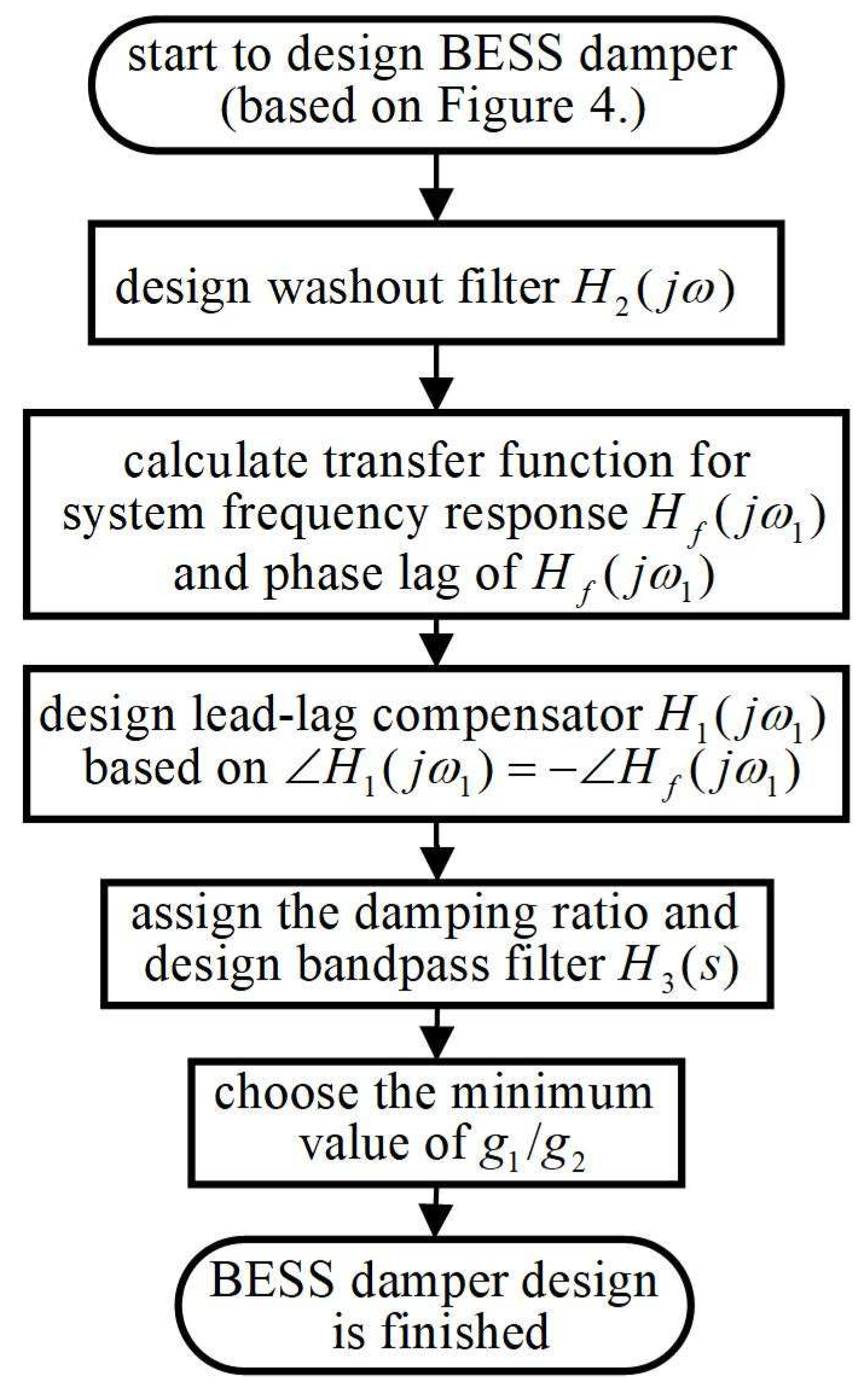
4.1. Design of Feedforward Compensator

If we let s = j ω , then the transfer function for the washout filter H 2 ( s ) in (20) can be expressed as
H 2 ( j ω ) = j ω j ω + ω C M P
Note that H 2 ( j ω )     1 when ω   = ω r =   ω 1   = 2 π   ×   2.92   = 18.35 since ω     ω CMP   = 2 [2]. Note also that H 2 ( j ω )     0 when ω     0 . Thus, speed signals Δ ω G of very low frequency are filtered out and mode 1 oscillation signals (with a frequency of ω 1   = 18.35) are allowed to pass. In a similar manner, bandpass filter H 3 ( s ) in (20) can be approximated as
H 3 ( j ω 1 ) g 2 g 1 ω 1
By substituting the system parameters in the Appendix A ( H T   = 0.675, T D   = 0.35, D = 0.5, K PD   = 20, K pw   = 20, ω G 0   = 0.94, B sys   = 5, B wind   = 1.5, B BESS   = 0.5, B D   = 2.25) into (22), we obtain the transfer function for system frequency response as follows:
H f ( s ) = 1 + 0.35 s s 2 ( 0.4725 ) + s ( 4.199 ) + 17.14
If we let s = j ω , then we obtain the following:
H f ( j ω ) = 1 + 0.35 j ω ( 0.4725 ω 2 + 17.14 ) + j ω ( 4.199 )
The transfer function at the mode 1 frequency of ω 1   = 18.35 can be written as
H f ( j ω 1 ) = 1 + j 6.4225 142 + j ( 77.05 )
and the phase lag of H f ( j ω 1 ) is
H f ( j ω 1 ) = 70.36 °
Note that the torque provided by the BESS damper, Δ T Gdamper , at the mode 1 frequency can be derived using Equations (20), (21), and (23) as follows:
Δ T G d m a p e r ( j ω 1 ) = H 1 ( j ω 1 ) H 2 ( j ω 1 ) H 3 ( j ω 1 ) H f ( j ω 1 ) B BESS ( K P W ) B s y s Δ ω G
In order for the BESS damper to provide best damping effect for torsional mode 1, it is essential that torque Δ T Gdamper ( j ω 1 ) be pure damping torque in phase with wind generator speed Δ ω G at mode 1 frequency ω 1 . Since H 2 ( j ω )     1 and H 3 ( j ω )     - g 2 / ( g 1 ω 1 ) when ω =   ω 1 , the feedforward compensator must compensate for the phase lag of H f ( j ω 1 ) . Thus, we obtain the following:
H 1 ( j ω 1 ) = H f ( j ω 1 ) = 70.36 °
As shown in Figure 4, we developed a second-order lead-lag compensator for phase compensation. Let T Z   = 1, such that the transfer function H 1 ( j ω 1 ) for the lead-lag network in Figure 4 can be expressed as follows:
H 1 ( j ω 1 ) = ( j ω 1 + 1 j ω 1 + 1 T P ) 2
The desired constant T P for the lead-lag compensator can be computed using Equations (31) and (32), as follows:
T P = 0.069

4.2. Design of Bandpass Filter

Table 2 lists the eigenvalues for torsional mode 1, λ 1   =   σ 1   +   j ω 1   = −0.57 ± j18.36 as computed using Equation (19) for a microgrid with BESS droop control ( K BESS   = 20) but without a BESS damper ( g 2   = 0). The damping ratio for mode 1 is as follows [56]:
ζ = sin θ = σ 1 σ 1 2 + ω 1 2 = 0.031
This eigenvalue λ 1 is very close to the imaginary axis and the damping ratio is not satisfactory. The proposed constant damping ratio method involves moving the unsatisfactory eigenvalue ( λ 1 ) to a pre-determined location with the aim of obtaining a constant damping ratio that is better than the original value of 0.031.
The real part of the desired mode 1 eigenvalue, σ 1 , is computed for a specific angular frequency ω 1 using Equation (34). Substituting the desired eigenvalue λ 1 = σ 1 + j ω 1 into Equation (19) renders the following:
a 18 ( σ 1 + j ω 1 ) 18 + a 17 ( σ 1 + j ω 1 ) 17 + + a 0 = 0
By separating the real part and imaginary part, Equation (35) can be rearranged as
c 1 g 1 + c 2 g 2 + c 3 + j c 4 g 1 + c 5 g 2 + c 6 = 0
The desired BESS damper constant can be obtained by solving the following two equations:
c 1 g 1 + c 2 g 2 + c 3 = 0
c 4 g 1 + c 5 g 2 + c 6 = 0
Note that different eigenvalues yield different damper constants ( g 1 and g 2 ) with a corresponding effect on system performance (e.g., frequency nadir after a step load change).
Figure 5 depicts the real part of eigenvalue σ 1 , BESS damper constants g 1 and g 2 , and frequency nadir as functions of mode 1 frequency ω 1 in the case where B BESS   = 0.5 MW, K BESS   = 20, and ζ 1   = 0.25. As shown in Figure 5c, a frequency range of 11.0 ω 1 17.1 appears to be appropriate, as evidenced by a small BESS damper gain. In the current study, we selected frequency ω 1 to yield the smallest damper gain g 2 in order to minimize BESS output power. Figure 5a also shows that varying mode 1 frequency ω 1 yielded a corresponding change in the real part of mode 1 eigenvalue σ 1 , while the system frequency nadir remained essentially unchanged.
The flowchart in Figure 6 highlights the steps of the BESS damper design process.

5. Simulation Results

Simulations in MATLAB/SIMULINK were conducted to assess the effectiveness of the proposed BESS torsional damper in terms of dynamic system responses to load disturbance and variations in wind speed, the results of which are listed in Figure 1. Note that the sampling time (time step) used in the simulation was 0.0001 s.

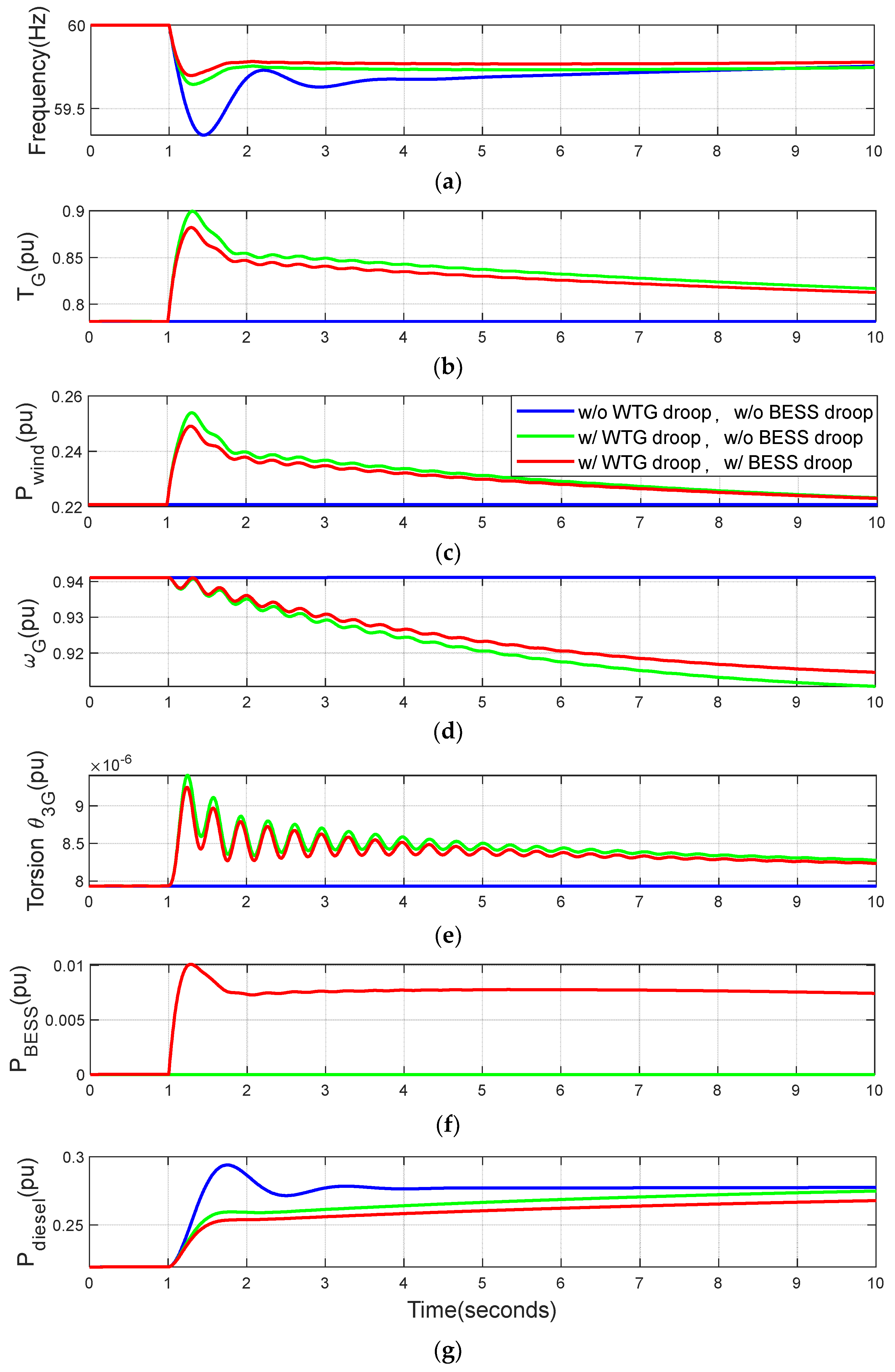
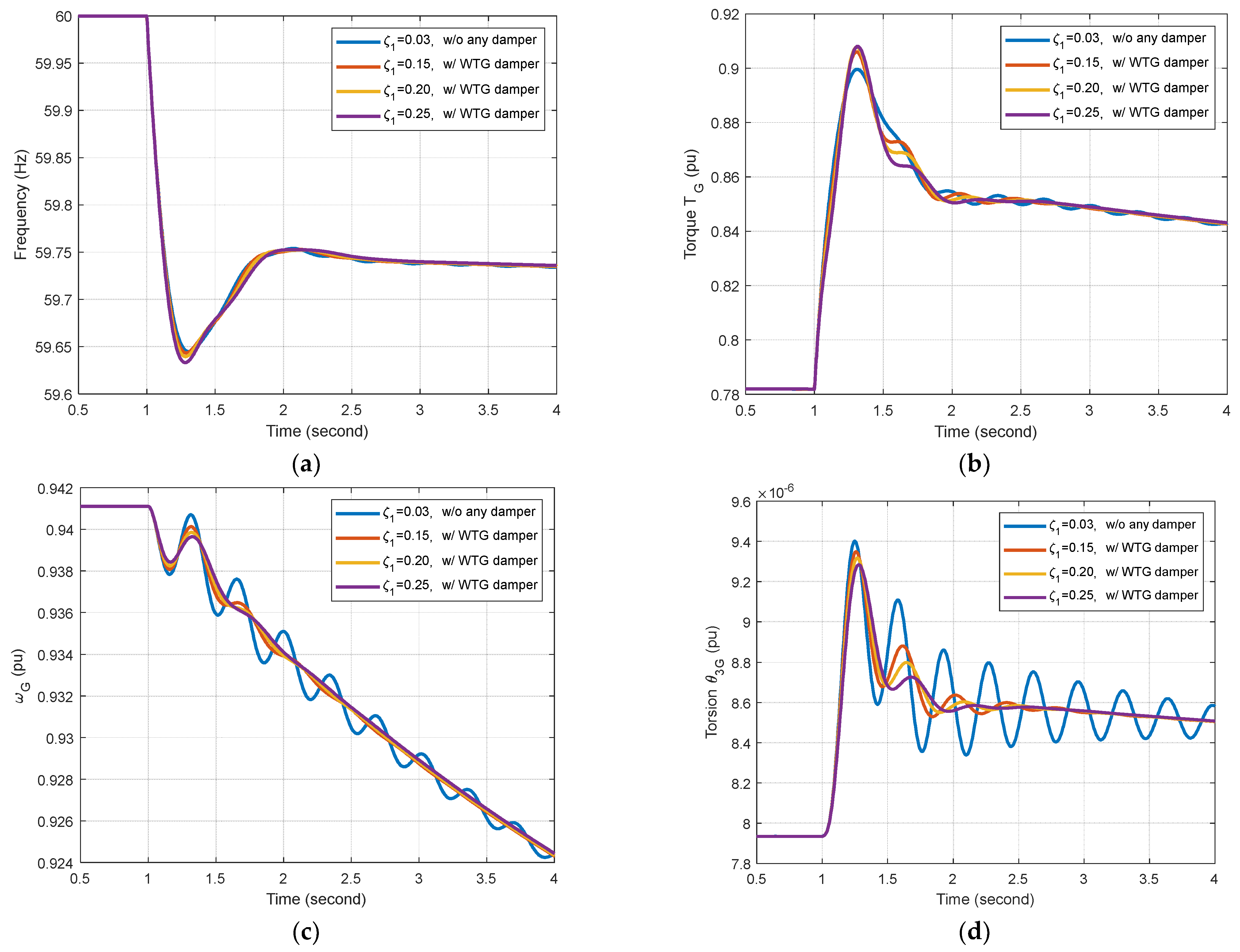
5.1. Effects of Wind Turbine Generator (WTG) Droop Control on Torsional Mode Oscillations: Microgrid without BESS Damper

As mentioned in Section 3.1 (Table 1), underdamped torsional mode 1 can be triggered by load disturbance in a DFIG with droop control. This is due to the fact that the oscillation frequency is close to the system frequency mode when using the system frequency as an input for the droop controller. The effect of droop control on mode 1 oscillation in a microgrid without a BESS damper is illustrated by the simulation results in Figure 7 showing dynamic response curves and FFT spectra as the grid is subjected to a 10% step load increase at t = 1 s.
As shown in Figure 7a, the frequency nadir was improved from 59.4 Hz to 59.7 Hz when droop control was employed for the wind turbine generator. This improvement can be attributed to increases in wind generator torque and power, respectively, shown in Figure 7b,c. Note however that the use of droop control triggered mode 1 oscillations, as indicated by generator speed ω G and torsion θ 3 G , respectively, shown in Figure 7d,e. The response curves in Figure 7a,f revealed that BESS droop control with a gain of K BESS   = 20 increased the BESS output power, P BESS , from zero to 0.01~0.007 p.u., as well as the frequency nadir from 59.7 Hz to 59.72 Hz. As shown in Figure 7d,e, mode 1 damping remained essentially unchanged when the BESS droop control gain was increased from K BESS   = 0 to K BESS   = 20. These results from time domain simulations are consistent with those from modal analysis in Table 2.
In Figure 8b, the two curves revealed an oscillation frequency of roughly 2.9 Hz in the Fast Fourier Transform (FFT) spectra of torsions θ 3 G under the effects of wind turbine droop control. The FFT spectra in Figure 8b also revealed that step load disturbances triggered only mode 1 oscillations at a frequency of 2.9 Hz. As shown in Table 1, no excitation was observed in the other torsional modes, including mode 2 (292 Hz), mode 3 (372 Hz), and mode 4 (1974 Hz). In addition, our analysis of system frequency in the FFT spectra revealed that step load disturbance triggered frequency mode oscillations at roughly 0.67 Hz.
The fact that step load changes triggered only frequency mode oscillations (0.67 Hz) and torsional mode 1 oscillations (2.9 Hz) (i.e., not torsional modes 2, 3, or 4) can be explained by the FFT spectrum in Figure 9b for the step input in Figure 9a. Here, the magnitudes in frequency mode (0.67 Hz) and torsional mode 1 (2.9 Hz) exceeded 300, whereas the magnitudes in mode 2 (292 Hz), mode 3 (372 Hz), and mode 4 (1974 Hz) were less than 10. This explains the triggering of frequency mode and torsional mode 1 oscillations by step load changes in Figure 7 and Figure 8.
Figure 10 presents dynamic response curves of the microgrid subjected to a 10% step load change, illustrating the effects of BESS droop gain ( K BESS   = 20, 25, and 30) without a BESS damper.
The response curves in Figure 10a revealed an increase in the frequency nadir with an increase in BESS droop gain. Increasing BESS droop gain decreased the torque and power of the wind generator (see Figure 10b,c), increased BESS power (see Figure 10f), and had only a small effect on damping for mode 1 (see Figure 10d,e). Taken together, we selected a droop gain of 20 as the optimal trade-off between frequency performance and battery SOH.

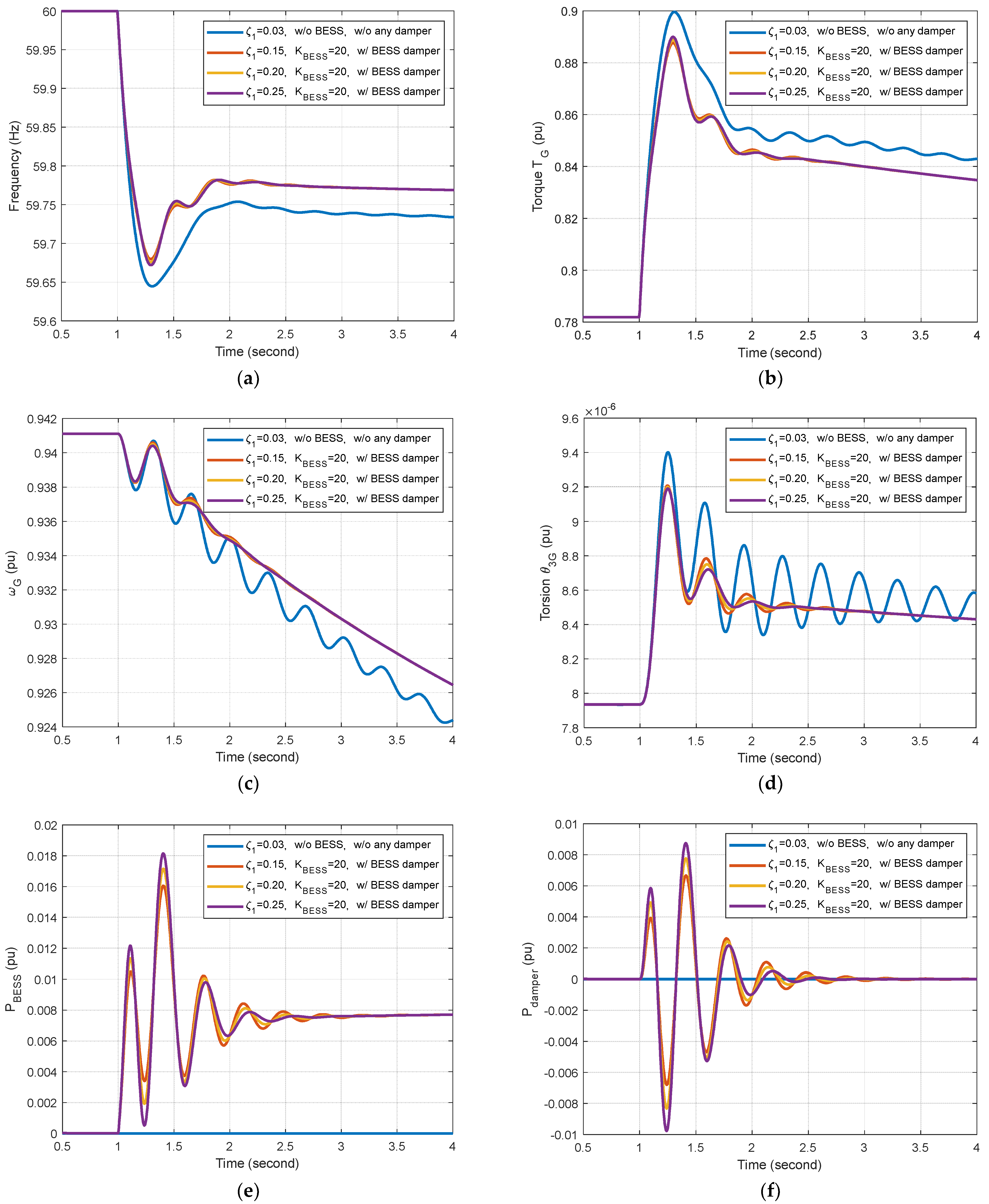
5.2. Effects of BESS Damper on Torsional Oscillation: Microgrid with a BESS Damper

To improve the damping for torsional mode 1 in Figure 7, the BESS damper designed in Section 4 was applied to the BESS. The constants used in the simulation were as follows: K pw =   20, K BESS = 20, ζ 1 =   0.25, 0.2, and 0.15. The simulated dynamic response curves are shown in Figure 11.
A comparison of response curves with and without the BESS damper in Figure 11b–d revealed a notable improvement in damping for mode 1. These results met our goal of increasing the damping ratio for mode 1 from 0.031 to 0.25 (see Section 4). Figure 11a revealed a slight increase in the frequency nadir (from 59.65 Hz to 59.67 Hz) when the BESS damper was applied. We also observed a change in BESS power ( P BESS   i n  Figure 11e) following the application of damper signal ( P damper in Figure 11f) to the BESS.
The design of BESS damper allows for the selection of damping ratios for torsional mode 1. Table 4 summarizes the variations in damper constants as a function of damping ratio ( ζ 1 = 0.25, ζ 1 = 0.2, or ζ 1 = 0.15).
As shown in Figure 11b–d, increasing the damping ratio ζ 1 from 0.15 to 0.25 produced a notable improvement in mode 1 damping.

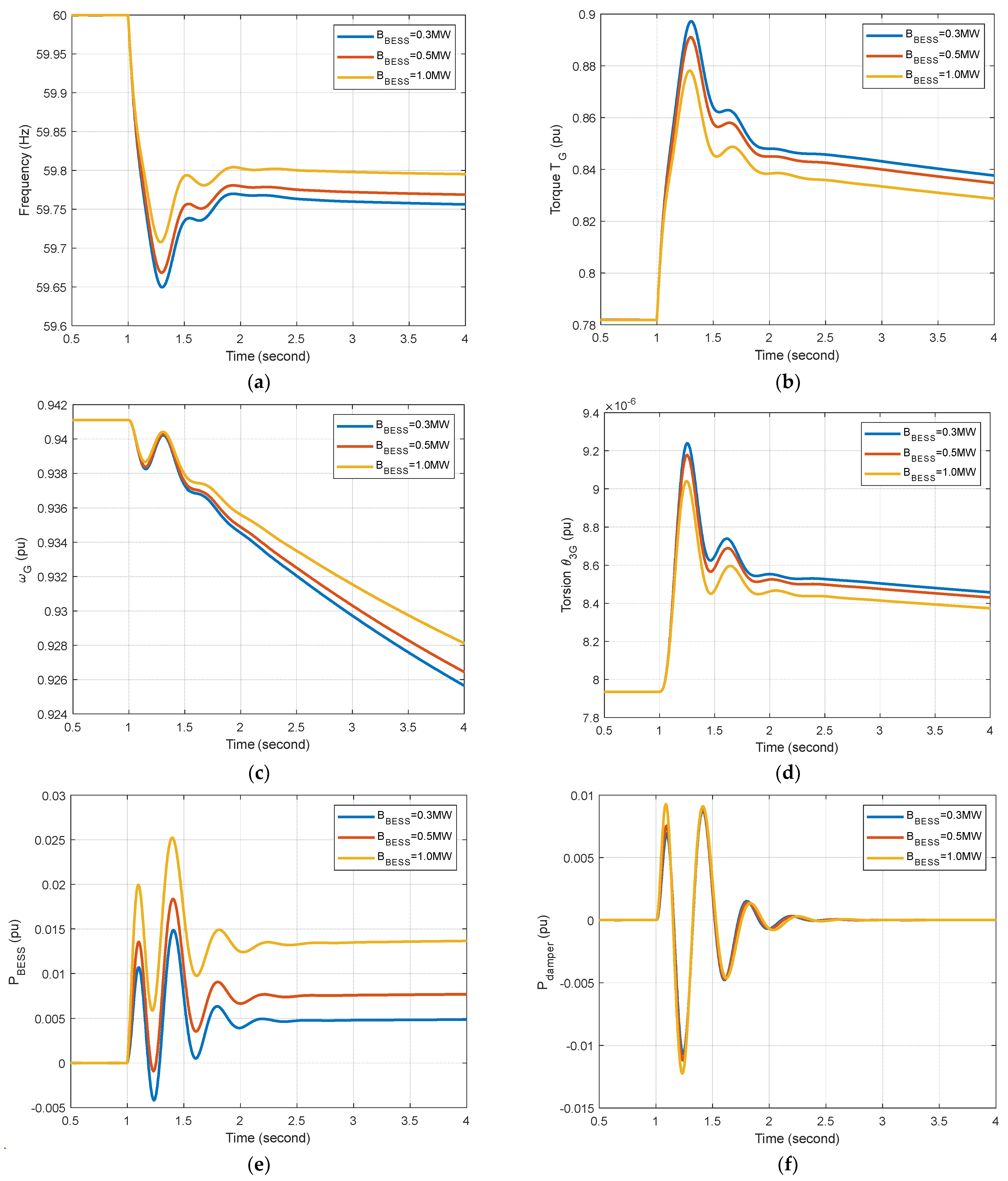
5.3. Effects of BESS Capacity on Dynamic Performance

To examine the effect of BESS capacity on the dynamic performance of the microgrid, we designed BESS dampers for three BESS capacities ( B BESS = 0.3 MW, B BESS = 0.5 MW, and B BESS = 1.0 MW) using the method outlined in Section 4, the results of which are listed in Table 5.
Figure 12 presents the dynamic response curves of the microgrid subjected to a 10% step load change under the three BESS capacities in Table 5. As shown in Figure 12a, using a BESS with large capacity was shown to improve the frequency nadir. Figure 12d shows that better torsional damping can be achieved with larger BESS capacities. Increasing BESS capacity was also shown to increase BESS damper output P damper (Figure 12f) and BESS output power P BESS (Figure 12e).

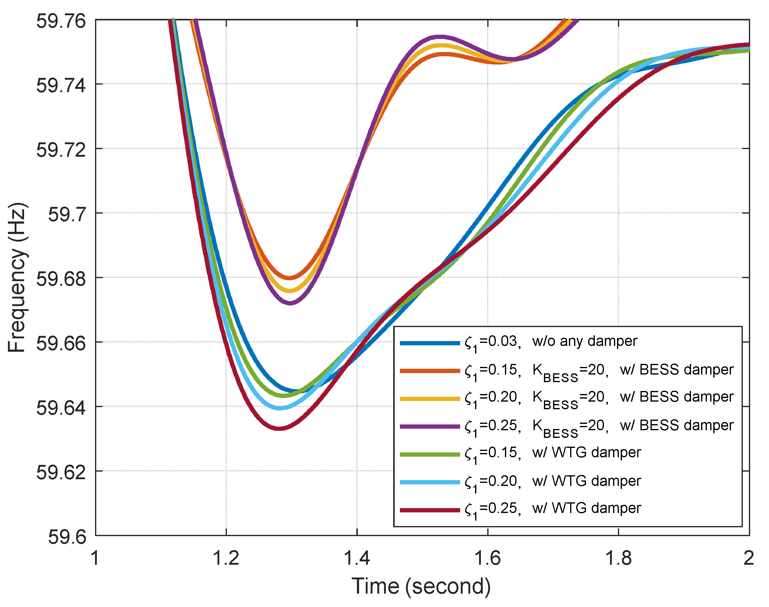
5.4. Comparison with Wind Turbine Generator (WTG) Damper

The dynamic performance of a grid equipped with a BESS damper was compared with that of a grid using a wind turbine generator damper [2] in terms of response curves under the effects of a 10% step load change, the results of which are presented in Figure 13 and Figure 14 and Table 6.
As shown in Figure 14 and Table 6, the frequency nadir for the microgrid with a BESS damper (59.6726 Hz for ζ 1   = 0.25) was higher than that of the microgrid with a WTG damper (59.6331 Hz for ζ 1   = 0.25). In addition, the response curves obtained from the microgrid with a BESS damper (Figure 13b–d) were similar to those from the microgrid with a WTG damper (Figure 11b–d).

5.5. Wind Speed Step Change

Figure 15 presents the dynamic responses of a microgrid subjected to a stepped decrease in wind speed.
As shown in Figure 15b–d, the BESS damper improved the damping ratio for torsional mode 1 under the effects of a step change in wind speed. As shown in Figure 15e, the power delivered to the system by the BESS increased with the damping ratio.

6. Conclusions

This paper presents a BESS damper with the aim of improving the damping ratio for the torsional mode oscillations in a microgrid comprising diesel generators and wind generators. We formulated a complete linearized model that includes diesel generators, a wind turbine with five-mass drivetrain, and a BESS in order to derive the transfer function between the BESS damper signal and DFIG torque. We developed a feedforward mechanism to compensate for the phase lag between the BESS damper signal and DFIG torque. We also designed a bandpass filter to shift the torsional mode eigenvalues leftward to points along a line with the aim of improving the damping ratio on the complex plane. The effectiveness of the proposed BESS damper was assessed in terms of dynamic responses in a microgrid subject to load changes and wind fluctuations using simulations implemented MATLAB/SIMULINK. This analysis led to the following conclusions:
(1)
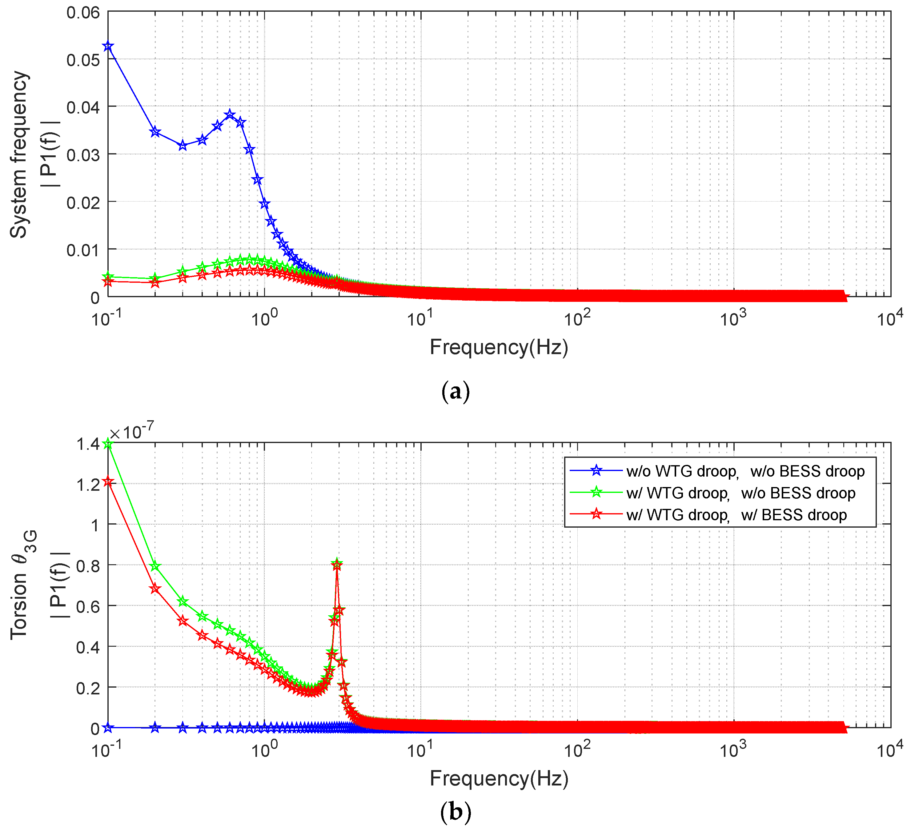
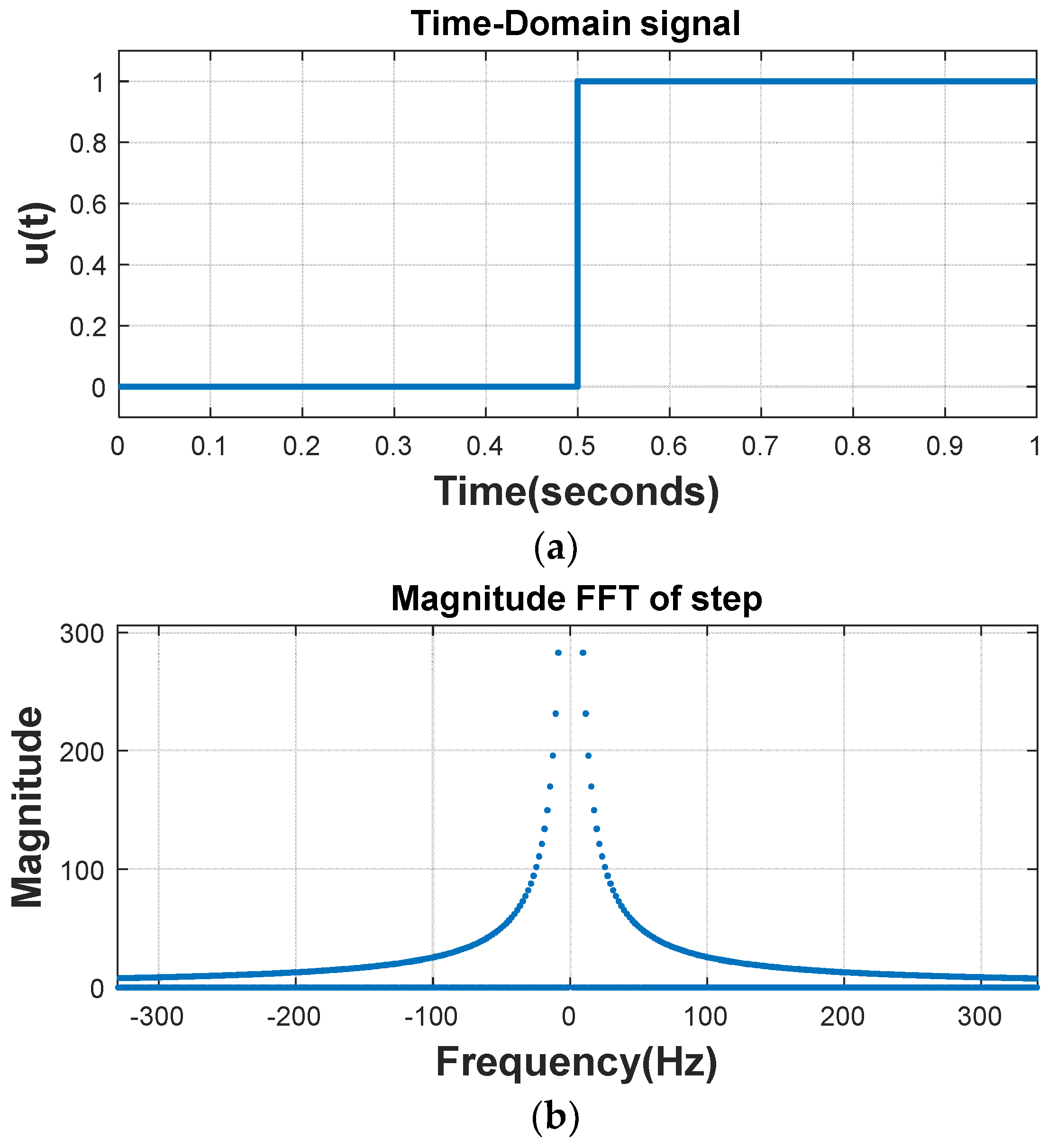
Based on FFT spectra of step responses, we determined that only torsional mode 1 (2.92 Hz) was excited by step load changes in the microgrid. Thus, this study focused exclusively on mode 1 in the design of the BESS damper.
(2)
Providing suitable compensation for the phase lag between the BESS damping signal and DFIG torque made it possible for the BESS damper to provide a damping signal capable of generating damping torque in phase with DFIG speed.
(3)
The proposed BESS damper improved the damping ratio for torsional mode 1 from 0.0319 to 0.25.
(4)
When using the feedforward compensator to deal with phase lag, the damping characteristics of the BESS damper were similar to those obtained using a DFIG damper. Note, however, that the frequency nadir obtained using the BESS damper (59.6726 Hz) exceeded that obtained using the DFIG damper (59.6331 Hz), due to the fact that the damping power was from a BESS instead of a DFIG.
(5)
The proposed BESS damper improved torsional mode damping in situations involving changes in wind speed, as well as stepped changes in load.
(6)
In microgrids with low system inertia, frequency deviations are relatively large and the torsional mode damping ratio is relatively small.
(7)
The proposed feedforward compensator proved effective in dealing with the phase lag between BESS power output and DFIG torque. As a result, the proposed BESS damper provided essentially the same damping effects as those reported in previous works, in which the damper was installed on rotor-side converters (RSCs) while avoiding the degradation of frequency response associated with dampers on the RSC.
(8)
BESS damper constants have been designed based on a specific operating condition. Future work will focus on the adaptation of BESS damper constants in accordance with system operating conditions, such as the number of diesel units and wind generators.

Author Contributions

Conceptualization, B.-K.C.; Methodology, B.-K.C.; Software, B.-K.C.; Validation, B.-K.C.; Investigation, B.-K.C. and K.-Y.L.; Data curation, B.-K.C. and K.-Y.L.; Writing—original draft, Y.-Y.H.; Writing—review & editing, K.-Y.L.; Visualization, B.-K.C.; Supervision, Y.-Y.H.; Project administration, Y.-Y.H. All authors have read and agreed to the published version of the manuscript.

Funding

This research was funded by the National Science and Technology Council of Taiwan, grant number MOST 111-2221-E-002-101; the APC was also funded by the National Science and Technology Council of Taiwan.

Data Availability Statement

The data are not publicly available due to privacy.

Acknowledgments

This work was supported by the National Science and Technology Council of Taiwan under contract MOST 111-2221-E-002-101.

Conflicts of Interest

The authors declare that they have no known competing financial interests or personal relationships that could have appeared to influence the work reported in this paper.

Nomenclature

BESS battery energy voltage system
B BESS , B D , B sys , B wind bases for BESS, diesel generators, system, and wind generators, respectively
D load damping
f system frequency
f int integral of system frequency
g 1 , g 2 bandpass filter parameters
H 1 , H 2 , H 3 , H G , H R inertia constants for 5-mass drivetrain of the wind turbine generator
H T inertia constants for diesel generator
K 1 , K 2 , K 3 , K 4 stiffness coefficients for 5-mass drivetrain of the wind generator
K PD , K pw , K BESS droop gains of diesel generators, wind generators, and BESS
K opt MPPT gain parameter
P BESS , P diesel , P wind , P load output powers of BESS, diesel generators, and wind generators, respectively, and load power
T D diesel generator time constants
T G , T R electromagnetic and mechanical torque of the wind generator
T Z , T P lead-lag compensator parameters
V W wind velocity
ω G wind generator speed
β pitch angle
θ 1 R , θ 12 , θ 23 , θ 3 G 5-mass drivetrain torsion
λ TSR tip speed ratio
ζdamping ratio
Δ linearized incremental quantity

Appendix A

System parameters:
  • B sys = 5 MVA
  • H T =   0.675 s
  • D =   0.5 p.u.
Diesel (synchronous) generator parameters:
  • K PD =   20 p.u.
  • K ID = 0.1 p.u.
  • T D =   0.35 s
  • B D = 2.25 MVA
Wind generator (doubly-fed induction generator) parameters:
  • B wind =   1.5 MVA
  • K PW =   20 p.u.
  • K 1 =   387 p.u.
  • K 2 =   5708 p.u.
  • K 3 =   799,438 p.u.
  • K 4 =   98,537 p.u.
  • H T =   5.2322 s
  • H 1 = 0.0007 s
  • H 2 =   0.0042 s
  • H 3 =   0.0069 s
  • H G =   0.5684 s
BESS parameters:
  • B BESS   = 0.5 MVA
  • K BESS =   20 p.u.

References

  1. Manaz, M.A.M.; Lu, C.-N. Design of resonance damper for wind energy conversion system providing frequency support service to low inertia power systems. IEEE Trans. Power Syst. 2020, 35, 4297–4306. [Google Scholar] [CrossRef]
  2. Mandic, G.; Nasiri, A.; Muljadi, E.; Oyague, F. Active torque control for gearbox load reduction in a variable-speed wind turbine. IEEE Trans. Ind. Appl. 2012, 48, 2424–2432. [Google Scholar] [CrossRef]
  3. Fateh, F.; White, W.N.; Gruenbacher, D. Torsional vibrations mitigation in the drivetrain of DFIG-based grid-connected wind turbine. IEEE Trans. Ind. Appl. 2017, 53, 5760–5767. [Google Scholar] [CrossRef]
  4. Bian, X.; Zhang, J.; Ding, Y.; Zhao, J.; Zhou, Q.; Lin, S. Microgrid Frequency Regulation Involving Low-wind-speed Wind Turbine Generators Based on Deep Belief Network. IET Gener. Transm. Distrib. 2020, 14, 2046–2054. [Google Scholar] [CrossRef]
  5. Van de Vyver, J.; De Kooning, J.D.M.; Meersman, B.; Vandevelde, L.; Vandoorn, T.L. Droop control as an alternative inertial response strategy for the synthetic inertia on wind turbines. IEEE Trans. Power Syst. 2016, 31, 1129–1138. [Google Scholar] [CrossRef]
  6. Hwang, M.; Muljadi, E.; Park, J.W.; Sørensen, P.; Kang, Y.C. Dynamic droop–based inertial control of a doubly-fed induction generator. IEEE Trans. Sustain. Energy 2016, 7, 924–933. [Google Scholar] [CrossRef]
  7. Lee, J.; Jang, G.; Muljadi, E.; Blaabjerg, F.; Chen, Z.; Kang, Y.C. Stable short-term frequency support using adaptive gains for a DFIG-based wind power plant. IEEE Trans. Energy Convers. 2016, 31, 1068–1079. [Google Scholar] [CrossRef]
  8. Lee, J.; Muljadi, E.; Srensen, P.; Kang, Y.C. Releasable Kinetic Energy-Based Inertial Control of a DFIG Wind Power Plant. IEEE Trans. Sustain. Energy 2016, 7, 279–288. [Google Scholar] [CrossRef]
  9. Abouzeid, S.I.; Guo, Y.; Zhang, H.C.; Ma, X. Improvements in primary frequency regulation of the grid-connected variable speed wind turbine. IET Renew. Power Gener. 2019, 13, 491–499. [Google Scholar] [CrossRef]
  10. Yang, P.; He, B.; Wang, B.; Dong, X.; Liu, W.; Zhang, J.; Wu, Z.; Liu, J.; Qin, Z. Coordinated control of rotor kinetic energy and pitch angle for large-scale doubly fed induction generators participating in system primary frequency regulation. IET Renew. Power Gener. 2021, 15, 1836–1847. [Google Scholar] [CrossRef]
  11. Roozbehani, S.; Hagh, M.T.; Zadeh, S.G. Frequency control of islanded wind-powered microgrid based on coordinated robust dynamic droop power sharing. IET Gener. Transm. Distrib. 2019, 13, 4968–4977. [Google Scholar] [CrossRef]
  12. Garmroodi, M.; Verbič, G.; Hill, D.J. Frequency support from wind turbine generators with a time-variable droop characteristic. IEEE Trans. Sustain. Energy 2018, 9, 676–684. [Google Scholar] [CrossRef]
  13. Wu, Y.K.; Yang, W.H.; Hu, Y.L.; Dzung, P.Q. Frequency regulation at a wind farm using time-varying inertia and droop controls. IEEE Trans. Ind. Appl. 2019, 55, 213–224. [Google Scholar] [CrossRef]
  14. Kumar, A. Primary frequency regulation support through deloaded offshore renewable power generators with HVDC-link. IET Renew. Power Gener. 2021, 15, 1693–1705. [Google Scholar] [CrossRef]
  15. Persson, M.; Chen, P. Frequency control by variable speed wind turbines in islanded power systems with various generation mix. IET Renew. Power Gener. 2017, 11, 1101–1109. [Google Scholar] [CrossRef]
  16. De Oliveira, J.D.A.; de Araújo Lima, F.K.; Tofoli, F.L.; Branco, C.G.C. Synchronverter-based frequency control technique applied in wind energy conversion systems based on the doubly-fed induction generator. Electr. Power Syst. Res. 2023, 214, 108820. [Google Scholar] [CrossRef]
  17. Vasudevan, K.R.; Ramachandaramurthy, V.K.; Babu, T.S.; Pouryekta, A. Synchronverter: A comprehensive review of modifications, stability assessment, applications, and future perspectives. IEEE Access 2020, 8, 131565–131589. [Google Scholar] [CrossRef]
  18. Din, Z.; Zhang, J.; Xu, Z.; Zhang, Y.; Milyani, A.H.; Cheema, K.M.; Nawaz, A.; Song, Y. Recent development and future trends of resonance in doubly fed induction generator system under weak grid. IET Renew. Power Gener. 2022, 16, 807–834. [Google Scholar] [CrossRef]
  19. Gu, K.; Wu, F.; Zhang, X.P. Sub-synchronous interactions in power systems with wind turbines: A review. IET Renew. Power Gener. 2019, 13, 4–15. [Google Scholar] [CrossRef]
  20. Bu, S.; Zhang, J.; Chung, C.Y. Damping torque analysis for open-loop modal resonance as a cause of torsional sub-synchronous oscillations excited by grid-connected wind farms. IET Renew. Power Gener. 2023, 17, 604–616. [Google Scholar] [CrossRef]
  21. Li, Y.; Fan, L.; Miao, Z. Replicating real-world wind farm SSR events. IEEE Trans. Power Del. 2020, 35, 339–348. [Google Scholar] [CrossRef]
  22. Leon, A.E. Integration of DFIG-based wind farms into series-compensated transmission systems. IEEE Trans. Sustain. Energy 2016, 7, 451–460. [Google Scholar] [CrossRef]
  23. Gu, Y.; Liu, J.; Green, T.C.; Li, W.; He, X. Motion-induction compensation to mitigate sub-synchronous oscillation in wind farms. IEEE Trans. Sustain. Energy 2020, 11, 1247–1256. [Google Scholar] [CrossRef]
  24. Leon, A.E.; Amodeo, S.J.; Mauricio, J.M. Enhanced compensation filter to mitigate subsynchronous oscillations in series-compensated DFIG-based wind farms. IEEE Trans. Power Deliv. 2021, 36, 3805–3814. [Google Scholar] [CrossRef]
  25. Karunanayake, C.; Ravishankar, J.; Dong, Z.Y. Nonlinear SSR damping controller for DFIG based wind generators interfaced to series compensated transmission systems. IEEE Trans. Power Syst. 2020, 35, 1156–1165. [Google Scholar] [CrossRef]
  26. Baesmat, H.J.; Bodson, M. Suppression of sub-synchronous resonances through excitation control of doubly fed induction generators. IEEE Trans. Power Syst. 2019, 34, 4329–4340. [Google Scholar] [CrossRef]
  27. Ghafouri, M.; Karaagac, U.; Karimi, H.; Jensen, S.; Mahseredjian, J.; Faried, S.O. An LQR controller for damping of subsynchronous interaction in DFIG-based wind farms. IEEE Trans. Power Syst. 2017, 32, 4934–4942. [Google Scholar] [CrossRef]
  28. Ghaffarzdeh, H.; Mehrizi-Sani, A. Mitigation of subsynchronous resonance induced by a type III wind system. IEEE Trans. Sustain. Energy 2020, 11, 1717–1727. [Google Scholar] [CrossRef]
  29. Ali, M.T.; Zhou, D.; Song, Y.; Ghandhari, M.; Harnefors, L.; Blaabjerg, F. Analysis and mitigation of SSCI in DFIG systems with experimental validation. IEEE Trans. Energy Convers. 2020, 35, 714–723. [Google Scholar] [CrossRef]
  30. Karaagac, U.; Mahseredjian, J.; Jensen, S.; Gagnon, R.; Fecteau, M.; Kocar, I. Safe operation of DFIG-based wind parks in series-compensated systems. IEEE Trans. Power Deliv. 2018, 33, 709–718. [Google Scholar] [CrossRef]
  31. Licari, J.; Ugalde-Loo, C.E.; Ekanayake, J.B.; Jenkins, N. Damping of torsional vibrations in a variable-speed wind turbine. IEEE Trans. Energy Convers. 2013, 28, 172–180. [Google Scholar] [CrossRef]
  32. Teleke, S.; Baran, M.E.; Bhattacharya, S.; Huang, A.Q. Optimal control of battery energy storage for wind farm dispatching. IEEE Trans. Energy Convers. 2010, 25, 787–794. [Google Scholar] [CrossRef]
  33. Zhang, S.; Mishra, Y.; Shahidehpour, M. Fuzzy-logic based frequency controller for wind farms augmented with energy storage systems. IEEE Trans. Power Syst. 2016, 31, 1595–1603. [Google Scholar] [CrossRef]
  34. Wu, Z.; Gao, D.W.; Zhang, H.; Yan, S.; Wang, X. Coordinated control strategy of battery energy storage system and PMSG-WTG to enhance system frequency regulation capability. IEEE Trans. Sustain. Energy 2017, 8, 1330–1343. [Google Scholar] [CrossRef]
  35. Datta, U.; Kalam, A.; Shi, J. Battery energy storage system to stabilize transient voltage and frequency and enhance power export capability. IEEE Trans. Power Syst. 2019, 34, 1845–1857. [Google Scholar] [CrossRef]
  36. Choi, J.W.; Heo, S.Y.; Kim, K.K. Hybrid operation strategy of wind energy storage system for power grid frequency regulation. IET Gener. Transm. Distrib. 2016, 10, 736–749. [Google Scholar] [CrossRef]
  37. Cao, J.; Du, W.; Wang, H.; McCulloch, M. Optimal Sizing and Control Strategies for Hybrid Storage System as Limited by Grid Frequency Deviations. IEEE Trans. Power Syst. 2018, 33, 5486–5495. [Google Scholar] [CrossRef]
  38. Kurian, S.; Krishnan, S.T.; Cheriyan, E.P. Real-time implementation of artificial neural networks-based controller for battery storage supported wind electric generation. IET Gener. Transm. Distrib. 2015, 9, 937–946. [Google Scholar] [CrossRef]
  39. Shim, J.W.; Verbič, G.; Zhang, N.; Hur, K. Harmonious integration of faster-acting energy storage systems into frequency control reserves in the power grid with high renewable generation. IEEE Trans. Power Syst. 2018, 33, 6193–6205. [Google Scholar] [CrossRef]
  40. Zhao, F.; Wang, X.; Zhou, Z.; Harnefors, L.; Svensson, J.R.; Kocewiak, L.H.; Gryning, M.P.S. Control interaction modeling and analysis of grid-forming battery energy storage system for offshore wind power plant. IEEE Trans. Power Syst. 2022, 37, 497–507. [Google Scholar] [CrossRef]
  41. Sebastián, R. Battery energy storage for increasing stability and reliability of an isolated wind-diesel power system. IET Renew. Power Gener. 2017, 11, 296–303. [Google Scholar] [CrossRef]
  42. Daraiseh, F. Frequency response of energy storage systems in grids with a high level of wind power penetration—Gotland case study. IET Renew. Power Gener. 2020, 14, 1282–1287. [Google Scholar] [CrossRef]
  43. Gu, F.C.; Chen, H.C. Modeling and control of vanadium redox flow battery for smoothing wind power fluctuation. IET Renew. Power Gener. 2021, 15, 3552–3563. [Google Scholar] [CrossRef]
  44. Pradhan, C.; Bhende, C.N.; Srivastava, A.K. Frequency sensitivity analysis of dynamic demand response in a wind farm integrated power system. IET Renew. Power Gener. 2019, 13, 905–919. [Google Scholar] [CrossRef]
  45. Krishan, O.; Suhag, S. Power management control strategy for a hybrid energy storage system in a grid-independent hybrid renewable energy system: A hardware-in-loop real-time verification. IET Renew. Power Gener. 2020, 14, 454–465. [Google Scholar] [CrossRef]
  46. Parthasarathy, C.; Sirviö, K.; Hafezi, H.; Laaksonen, H. Modeling battery energy storage systems for active network management—Coordinated control design and validation. IET Renew. Power Gener. 2021, 15, 2426–2437. [Google Scholar] [CrossRef]
  47. Mossa, M.A.; Echeikh, H.; Quynh, N.V.; Bianchi, N. Performance dynamics improvement of a hybrid wind/fuel cell/battery system for standalone operation. IET Renew. Power Gener. 2023, 17, 349–375. [Google Scholar] [CrossRef]
  48. Teodorescu, R.; Sui, X.; Vilsen, S.B.; Bharadwaj, P.; Kulkarni, A.; Stroe, D.-I. Smart battery technology for lifetime improvement. Batteries 2022, 8, 169. [Google Scholar] [CrossRef]
  49. Martyushev, N.V.; Malozyomov, B.V.; Khalikov, I.H.; Kukartsev, V.A.; Kukartsev, V.V.; Tynchenko, V.S.; Tynchenko, Y.A.; Qi, M. Review of Methods for Improving the Energy Efficiency of Electrified Ground Transport by Optimizing Battery Consumption. Energies 2023, 16, 729. [Google Scholar] [CrossRef]
  50. Park, J.; Choi, J.; Jo, H.; Kodaira, D.; Han, S.; Acquah, M.A. Life Evaluation of Battery Energy System for Frequency Regulation Using Wear Density Function. Energies 2022, 15, 8071. [Google Scholar] [CrossRef]
  51. Papakonstantinou, A.G.; Papathanassiou, S.A. Battery Energy Storage Participation in Automatic Generation Control of Island Systems, Coordinated with State of Charge Regulation. Appl. Sci. 2022, 12, 596. [Google Scholar] [CrossRef]
  52. Rancilio, G.; Rossi, A.; Di Profio, C.; Alborghetti, M.; Galliani, A.; Merlo, M. Grid-Scale BESS for Ancillary Services Provision: SoC Restoration Strategies. Appl. Sci. 2020, 10, 4121. [Google Scholar] [CrossRef]
  53. Shahabi, M.; Haghifam, M.R.; Mohamadian, M.; Nabavi-Niaki, S.A. Microgrid dynamic performance improvement using a doubly fed induction wind generator. IEEE Trans. Energy Convers. 2009, 24, 137–145. [Google Scholar] [CrossRef]
  54. Vidyanandan, K.V.; Senroy, N. Primary frequency regulation by deloaded wind turbines using variable droop. IEEE Trans. Power Syst. 2013, 28, 837–846. [Google Scholar] [CrossRef]
  55. Kundur, P. Power System Stability and Control; McGraw-Hill: New York, NY, USA, 1994. [Google Scholar]
  56. Franklin, G.F.; Powell, J.D.; Emami-Naeini, A. Feedback Control of Dynamic Systems; Pearson Education, Inc.: Upper Saddle River, NJ, USA, 2006. [Google Scholar]
Figure 1. One-line diagram of microgrid with the BESS examined in this study.
Energies 16 07439 g001
Figure 2. Linearized model of frequency control system for microgrid with BESS.
Energies 16 07439 g002
Figure 3. BESS equivalent circuit of the battery and block diagram of power controllers and current regulators.
Energies 16 07439 g003
Figure 4. Block diagram of BESS damper and system frequency response transfer function.
Energies 16 07439 g004
Figure 5. Real part of eigenvalue σ 1 , BESS damper constants g 1 and g 2 , and frequency nadir as functions of mode 1 frequency ω 1 ( B BESS   = 0.5 MW, K BESS   = 20, ζ 1   = 0.25): (a) real part of eigenvalue; (b) frequency nadir; (c) BESS damper constants g 1 and g 2 .
Energies 16 07439 g005
Figure 6. Flowchart showing BESS damper design process.
Energies 16 07439 g006
Figure 7. Dynamic response curves of microgrid without a BESS damper subjected to a 10% step load change at t = 1 s: (a) frequency, (b) torque T G , (c) P wind , (d) ω G , (e) torsion θ 3 G , (f) P BESS , (g) P diesel .
Energies 16 07439 g007
Figure 8. FFT spectra of microgrid without a BESS damper: (a) system frequency; (b) torsion θ 3 G .
Energies 16 07439 g008
Figure 9. FFT spectra of step response: (a) u(t); (b) magnitude.
Energies 16 07439 g009
Figure 10. Dynamic response curves of microgrid with BESS droop gain but without a BESS damper subjected to a 10% step load change: (a) frequency; (b) torque T G ; (c) P wind ; (d) ω G ; (e) torsion θ 3 G ; (f) P BESS .
Energies 16 07439 g010
Figure 11. Dynamic response curves of microgrid with a BESS damper subjected to a 10% step load change at t = 1 s ( K pw =   20): (a) frequency; (b) torque T G ; (c) ω G ; (d) torsion θ 3 G ; (e) P BESS ; (f) P damper .
Energies 16 07439 g011
Figure 12. Dynamic response curves of microgrid with BESS damper as a function of BESS capacity (10% step load change at t = 1 s, K pw   = 20, K BESS   = 20): (a) Frequency; (b) Torque T G ; (c) ω G ; (d) Torsion θ 3 G ; (e) P BESS ; (f) P damper .
Energies 16 07439 g012
Figure 13. Dynamic response curves of microgrid with WTG damper (10% step load change at t = 1 s, K pw =20, without BESS): (a) frequency; (b) torque T G ; (c) ω G ; (d) torsion θ 3 G .
Energies 16 07439 g013
Figure 14. Enlargement of frequency response curves in Figure 10a and Figure 12a.
Energies 16 07439 g014
Figure 15. Dynamic response curves obtained from a microgrid subjected to a 1 m/s stepped decrease in wind speed at t = 1 s. ( B BESS   = 0.5 MW, K pw   = 20, K BESS   = 20): (a) frequency; (b) torque T G ; (c) ω G ; (d) torsion θ 3 G ; (e) P BESS ; (f) P damper .
Energies 16 07439 g015
Table 1. Modal analysis of microgrid without BESS ( K pw = 20 , V w = 11 m/s).
ModeTorsional ModesFrequency Mode
01234
Eigenvalues−0.104−0.586 ± j18.58−9.1 × 10⁻³ ± j1834−5.74 × 10⁻³ ± j2334−7.61 × 10⁻⁶ ± j12405−3.79 ± j4.23
Oscillation frequency (Hz)02.921291.97371.521974.270.673
Damping ratio (ζ)10.03194.9 × 10−62.4 × 10−66.1 × 10−100.667
Table 2. Torsional mode 1 eigenvalues for the microgrid with BESS but without a BESS damper ( K pw = 20 , V w = 11   m /s).
Case 1Case 2Case 3Case 4
K BESS = 0 K BESS = 20
( R BESS = 0.05 )
K BESS = 25
( R BESS = 0.04 )
K BESS   = 30
( R BESS = 0.033 )
Eigenvalue−0.586 ± j18.58−0.57 ± j18.36−0.568 ± j18.365−0.564 ± j18.368
Frequency2.9212.9222.9232.923
Damping ratio0.03190.03100.03090.0307
Table 3. Frequency mode eigenvalues for the microgrid with BESS but without a BESS damper ( K pw = 20 , V w = 11 m/s).
Case 1Case 2Case 3Case 4
K BESS = 0 K BESS = 20
( R BESS = 0.50 )
K BESS = 25
( R BESS = 0.04 )
K BESS = 30
( R BESS = 0.033 )
Eigenvalue−3.79 ± j4.230−4.544 ± j3.992−4.733 ± j3.908−4.921 ± j3.812
Frequency0.6730.6350.6220.607
Damping ratio0.6670.7510.7710.791
Table 4. BESS damper constants as a function of damping ratio ( B BESS =   0.5 MW, K BESS = 20, K pw =   20).
ζ 1 g 2 g 1 g 2 / g 1 σ 1 ω 1
0.254518.082.01292244.58−4.0915.85
0.203877.372.09071854.59−3.5217.25
0.153019.892.03961480.62−2.6917.75
Table 5. BESS damper constants and frequency nadirs as a function of BESS capacity ( K pw = 20, K BESS = 20).
B BESS g 2 g 1 g 2 / g 1 f nadir
0.3 MW10485.572.59394042.3659.650
0.5 MW7971.393.05742607.2359.669
1.0 MW8285.955.31481559.0559.708
Table 6. Damping ratios and frequency nadirs of microgrid with a BESS damper vs. a WTG damper.
ζ 1 Frequency Nadir (Hz)
Without any damper0.0359.6447
With BESS damper0.1559.6803
0.2059.6764
0.2559.6726
With WTG damper0.1559.6434
0.2059.6395
0.2559.6331
Disclaimer/Publisher’s Note: The statements, opinions and data contained in all publications are solely those of the individual author(s) and contributor(s) and not of MDPI and/or the editor(s). MDPI and/or the editor(s) disclaim responsibility for any injury to people or property resulting from any ideas, methods, instructions or products referred to in the content.

