Article

Numerical Evaluation of Heat Transfer and Conversion Efficiency by Tube Design and Flow Configuration for a Compact Steam-Methane Reformer

1
School of Mechanical Engineering, Sungkyunkwan University, Suwon 16419, Republic of Korea
2
Korea Institute of Energy Research (KIER), Daejeon 34129, Republic of Korea
*
Author to whom correspondence should be addressed.
Energies 2023, 16(22), 7475; https://doi.org/10.3390/en16227475
Submission received: 5 October 2023 / Revised: 1 November 2023 / Accepted: 3 November 2023 / Published: 7 November 2023
(This article belongs to the Section A5: Hydrogen Energy)

Abstract

:
In the chemical industry, hydrogen (H2) production through steam-methane reforming is a well-established process. With the growing demand for H-fueled vehicles and charging stations, there is a need for compact reformers with efficient heat transfer capabilities. In this study, computational fluid dynamics simulations were performed to evaluate the methane (CH4) conversion and heat transfer efficiency of various reformer designs. These designs include single, double, and triple tubes, each with parallel- and counter-flow configurations between the reformate feed and heat source. The findings revealed substantial disparities in methane conversion between the tube designs and flow configurations. Notably, the triple-tube design outperforms single and double tubes, exhibiting higher methane conversion and improved heat transfer efficiency. This superior performance is attributed to the larger wall area facing the heat source and additional heat recovery from the reformate flowing in the inner annulus. This led to the highest temperature at the catalyst exit among the cases, increasing methane conversion, and the lowest reformate temperature at the reformer tube exit, which is also beneficial for the subsequent water–gas shift reaction process. Installing external fins on the reformer tube provided a more effective enhancement of heat transfer than using internal fins in the catalyst section. Regardless of the tube design employed, the counter-flow configuration consistently enhanced the heat transfer efficiency, resulting in 4.6–11.9% higher methane conversion than the parallel-flow configuration. Consequently, the triple-tube design with the counter-flow configuration achieved the highest methane conversion, offering flexibility in the reformer design, including the potential for lower heat input and a reduced catalyst volume.

1. Introduction

With the global focus on mitigating climate change, the demand for hydrogen as a low-carbon fuel has increased rapidly. While hydrogen has been extensively used in the petroleum and chemical industries, its applications in renewable energy storage, power generation, and the transport sector have only recently gained prominence as key technologies in the ongoing energy transition [1]. Hydrogen can be produced using various methods, including reforming, electrolysis, photocatalysis, thermochemical cycles, biohydrogen, and plasmolysis [2]. Among these methods, steam-methane reforming (SMR) utilizing natural gas constitutes 76% of the total global hydrogen production, followed by coal gasification (23%) and electrolysis (<1%) [3].
The hydrogen production process through SMR involves two main reactions: the SMR reaction (CH4+H2O↔CO+3H2) and the water–gas shift (WGS) reaction (CO+H2O↔CO2+H2), with both employing catalysts. The process comprises three main steps: Firstly, natural gas mixed with steam is reformed in an SMR reactor, typically at temperatures ranging from 700 to 1000 °C and pressures between 3 and 25 atm, to produce reformate gas [4]. Secondly, the reformate is processed via the WGS reaction to increase hydrogen content. Finally, hydrogen is purified while separating CO2, typically by pressure swing adsorption. For the first step, nickel-based non-precious metal catalysts are commonly used, although noble metals (such as rubidium and platinum) are also employed.
For hydrogen supply in refueling stations, two options are available: a centralized plant with distribution to the refueling stations and onsite distributed production [5]. The latter option necessitates a small and compact SMR reactor design, which uses natural gas as the feedstock. Additionally, there is a growing demand for compact reformers in hydrogen production from alternative feedstocks, such as biogas [6] and the pyrolytic vapor of waste plastics [7].
The development of a compact and efficient reformer has been a subject of extensive research in the literature, with a primary focus on optimizing both the design and operating parameters. The operating conditions of the input feed, such as temperature, flow rate, steam-to-carbon ratio, and pressure, must be optimized to increase hydrogen production while preventing carbon formation and catalyst deactivation [8,9,10,11,12]. Moreover, energy and exergy analyses have proven to be helpful in evaluating different operating parameters and improving the overall process efficiency [13,14,15].
Given that the SMR reactions are strongly endothermic and heat-transfer-limited, enhancing heat transfer is crucial in reformer design. Typically, the heat source involves hot flue gas generated from fuel gas combustion, which supplies heat to the reformer tube via convection and radiation. Alternatively, solar heat energy can also be employed as a heat source [16,17]. To enhance heat transfer, the arrangement of the catalyst tubes is a critical design parameter [18]. In particular, the counter-flow arrangement of the catalyst layer relative to the hot gas (heat source) and the uniform flow of the hot gas can increase heat transfer, resulting in higher methane conversion [19]. The burner configuration and the number of reformer tubes also significantly influence thermal efficiency and methane conversion [20,21].
The design of individual reforming tubes is an additional factor that can enhance heat transfer. Notably, double tubes (also known as bayonet tubes), in which the catalyst fills the outer annulus and the reformate flows out through the inner core, exhibit superior heat exchange performance than single tubes. This design has been applied to commercial SMRs [22] and other applications [23,24]. Lee et al. [25] compared the performances of single-tube and double-tube SMR reactors with a 100 Nm3/h hydrogen production rate using gPROMS ProcessBuilder. The double-tube configuration achieved higher methane conversion and lower reactor outlet temperature, mainly because of the additional recovery of reformate heat. Furthermore, in a study by Minette et al. [26], the installation of an insert in the inner core of a double tube enhanced the heat transfer, facilitating additional heat recovery from the reformate while incurring only a minor increase in the pressure drop.
The aforementioned studies demonstrate the importance of reforming tube design in enhancing heat transfer efficiency and optimizing reformers to save heat supply or catalyst volume. However, a more detailed analysis of different reformer tube designs is required to understand the changes in the contribution of heat transfer paths between the heat source, reformer tube, and reformate and their influences on methane conversion. This study investigated the fundamental aspects of reformer tube designs using computational fluid dynamics (CFD) by comprehensive analysis of heat transfer and methane conversion. For a reformer tube filled with a common Ni/MgAl2O4-based catalyst, single-, double-, and triple-tube designs with identical catalyst volumes were evaluated under two flow configurations (parallel- and counter-flow) against hot gas as a heat source in a simplified cylindrical reactor geometry. The operating conditions were taken from a commercial reformer. The results were analyzed in detail regarding the temperature distribution, reactions, and contributions of different heat transfer paths to understand the reasons for the varying methane conversions and heat transfer efficiencies. In addition, the pressure drop was evaluated as another crucial variable in process design. Finally, the reformate pressure was varied between 2.5 and 8.5 bar to identify the pressure effect on the methane conversion and pressure loss for the reformer tube designs. This information can be used to design compact SMRs.

2. Numerical Methods

2.1. Reformer Geometry and Operating Conditions

Figure 1 illustrates the different reformer tube designs of the simplified SMR reactor considered in this study. The reactor comprises a reformer tube at the center with hot gas flowing outside the tube. Single-, double-, and triple-tube designs were evaluated for the reformer tubes containing the same catalyst volume. In the single tube (Case 1), the entire tube volume was filled with the catalyst. In the double or bayonet tube (Case 2), the methane–steam mixture entered the outer annulus filled with the catalyst and escaped through the inner tube. In the triple-tube design, a hollow, closed core was added, while the reformate escaped through the inner annulus. Two different tube diameters were tested for a plain triple tube (Cases 3a and 3b), and two variants of internal fins were installed in Cases 3c and 3d for possible improvements in heat transfer and temperature uniformity. In Case 3c, six internal fins extended into the catalyst section from the outer wall, while in Case 3d, external fins extended to the heat source. In addition, the flow direction of the hot flue gas outside the reformer tube was evaluated for both parallel- and counter-flow configurations, wherein the hot gas entered from the bottom and top, respectively. Each simulation case was named after the flow configuration and tube design. For example, Cases P-1 and C-1 represent the single-tube designs in the parallel- and counter-flow configurations, respectively.
Table 1 lists the dimensions of the reformer tubes. To maintain consistency in the reactor and catalyst volumes across the cases, three design parameters were fixed: the internal diameter of the reformer (D1 = 331 mm), height (1500 mm), and cross-sectional area of the catalyst (7300 mm2), while D2–D4 vary depending on the catalyst tube design.
Table 2 lists the operating conditions of the reformer, which are based on the design conditions of a commercial reformer. The mixture of CH4 (25%) and H2O (75%) enters the catalyst section of the reformer tube at 500 °C with a flow rate of 0.0084 kg/s. The gas hourly space velocity was 6984 h-1, which is in the typical operation window [27]. The tube exit pressure was 6.5 bar in the reference condition, which corresponds to approximately 7 bar at the inlet. The influence of pressure was evaluated separately in the range of 2.5–8.5 bar. The heat source outside the tube was simplified to be flue gas at 1200 °C and 1 bar, with a flow rate of 0.0328 kg/s. The flue gas comprised 9.6% O2, 10.9% CO2, 12.4% H2O, and 67.1% N2. The amount of heat delivered by the flue gas corresponds to 1.9 times the amount of heat required to completely reform CH4. The catalyst section in the tube was filled with Ni/MgAl2O4 catalyst, having a bulk density of 3900 kg/m3, particle size ( D p ) of 5 mm, heat capacity of 880 J/kg·K, thermal conductivity of 33 W/m·K, and porosity ( γ ) of 0.5 [28].
Table 3 lists the boundary conditions for the walls of the reformer. The outer wall of the heat source was assumed to be adiabatic with an emissivity of 0.7, as it is typically well insulated and the focus of this study is to compare the performance of different reformer tube designs in a simplified condition. The reformer tube wall had an emissivity of 0.65 and a thermal conductivity of 23 W/mK.

2.2. Numerical Models

Numerical simulations of the reformer were performed using ANSYS Fluent (version 2020R1) [29]. The following three reactions were considered for methane conversion [30]:
[R1] CH4(g) + H2O(g) ⇆ CO(g) + 3H2(g)
[R2] CO(g) + H2O(g) ⇆ CO2(g) + H2(g)
[R3] CH4(g) + 2H2O(g) ⇆ CO2(g) + 4H2(g)
Several studies have been conducted to determine the rates associated with WGS reactions. The reaction rate model proposed by Xu and Froment [30] was used in this study.
r 1 = k 1 p H 2 2.5 p C H 4 p H 2 O p H 2 3 p C O K 1 / D E N 2
r 2 = k 2 p H 2 p C O p H 2 O p H 2 p C O 2 K 2 / D E N 2
r 3 = k 3 p H 2 3.5 p C H 4 p H 2 O 2 p H 2 4 p C O 2 K 3 / D E N 2
D E N = 1 + K H 2 O p H 2 O p H 2 + K C O p C O + K H 2 p H 2 + K C H 4 p C H 4
where pi and Ki denote the partial pressure and adsorption/dissociative adsorption constants of the chemical species i, respectively. To consider the overall diffusion effects, the effectiveness factor of 0.1 was multiplied by the above reaction rates [30,31]. The reaction model was implemented in ANSYS Fluent by using a user-defined function (UDF).
The pressure drop in the catalyst section was solved using the Ergun equation, which comprises viscous and inertial loss terms involving the gas superficial velocity ( v ) for the catalyst properties mentioned previously:
Δ P L = 150 μ D p 2 1 γ 2 γ 3 v + 1.75 ρ D p 1 γ γ 3 v 2
The hot gas in the heat source is in a turbulent flow regime with an average velocity and Reynolds number of 1.82 m/s and 9694 at the inlet, respectively. Because it flows in a straight channel with a small pressure gradient, the standard k-ε model [32] was employed with the enhanced wall treatment method for the near-wall region.
t ρ k + x i ρ k u i = x j μ + μ t σ k k x j + G k + G b ρ ε
t ρ ε + x i ρ ε u i = x j μ + μ t σ ε ε x j + C 1 ε ε k G k + C 3 ε G b C 2 ε ρ ε 2 k
C μ = 0.09 ,   C 1 ε = 1.44 ,   C 2 ε = 1.92 ,   σ k = 1.0 ,   σ ε = 1.3
The turbulent intensity at the inlet of the hot gas and reforming tube was set to 3%.
The radiation was considered using the discrete ordinate method, with an angular discretization of five divisions in the polar and phi directions, each with three subpixels. The participation of CO2 and H2O in hot gas in radiation was considered using the weighted sum of gray gases model with the model constants of Smith et al. [33].

2.3. Validation of Mesh Sensitivity

The mesh was constructed for the 1/6 of the geometry using a symmetry condition with 81,485 hexahedron cells. This mesh was selected after assessing its sensitivity by comparing the degree of numerical diffusion between coarser (39,880 cells) and finer (151,950 cells) meshes. Compared with the results for the finer mesh, the selected mesh exhibited minimal deviations in the key performance parameters: 0.01% in methane conversion, 0.04% in the rate of heat transfer to the catalyst, 0.09% in the flue gas exit temperature, and 0.01% in the reformate temperature at the tube exit. In contrast, the coarser meshes had deviations of 0.29, 0.35, 0.21, and 0.11%, respectively.

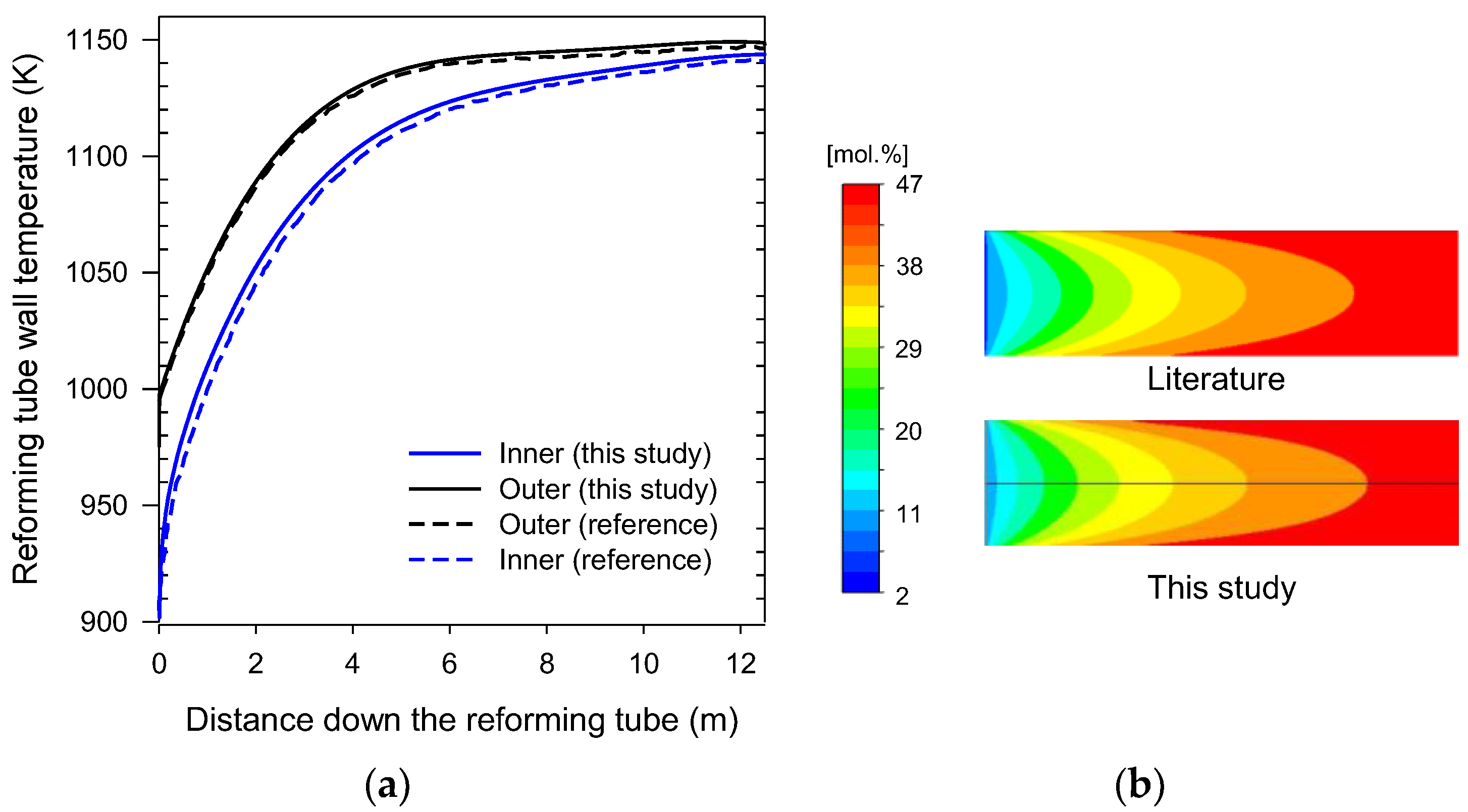
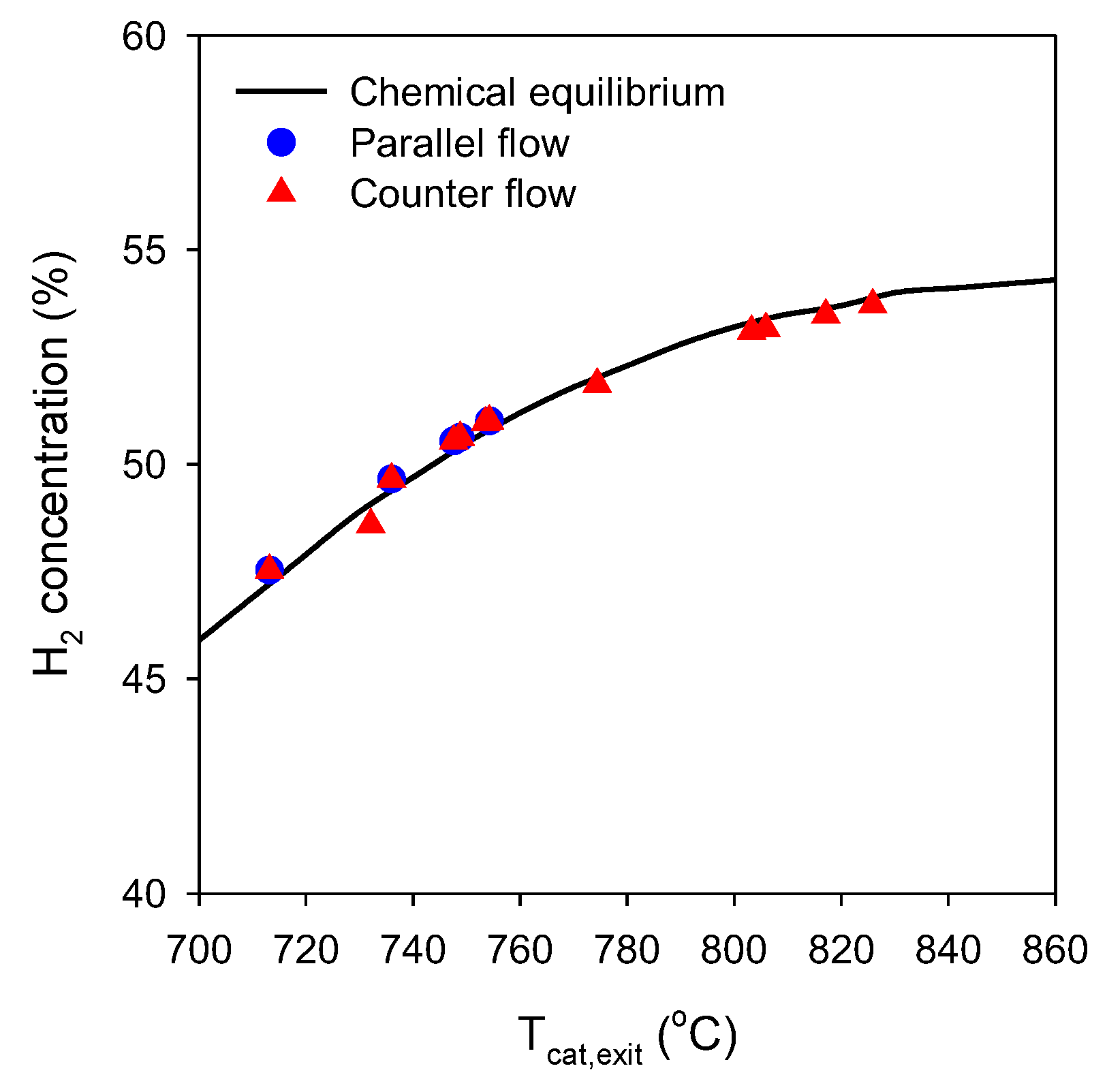
2.4. Validation of Numerical Models

The numerical model, including the UDF for the reaction model, was validated by reproducing the simulation data obtained by Lao et al. [28]. In this case, 0.1161 kg/s of a gas mixture (25% CH4 and 75% steam) entered the single catalyst tube at conditions of 887 K and 20 kPagauge. A mesh containing 60,000 cells was used in the simulation. As shown in Figure 2, the temperature profiles of the inner and outer walls, as well as the contour of the H2 mole fraction, closely matched those reported in the literature. The deviations in the inner and outer wall temperatures from the literature data were 0.44% and 0.22%, respectively.

3. Results and Discussion

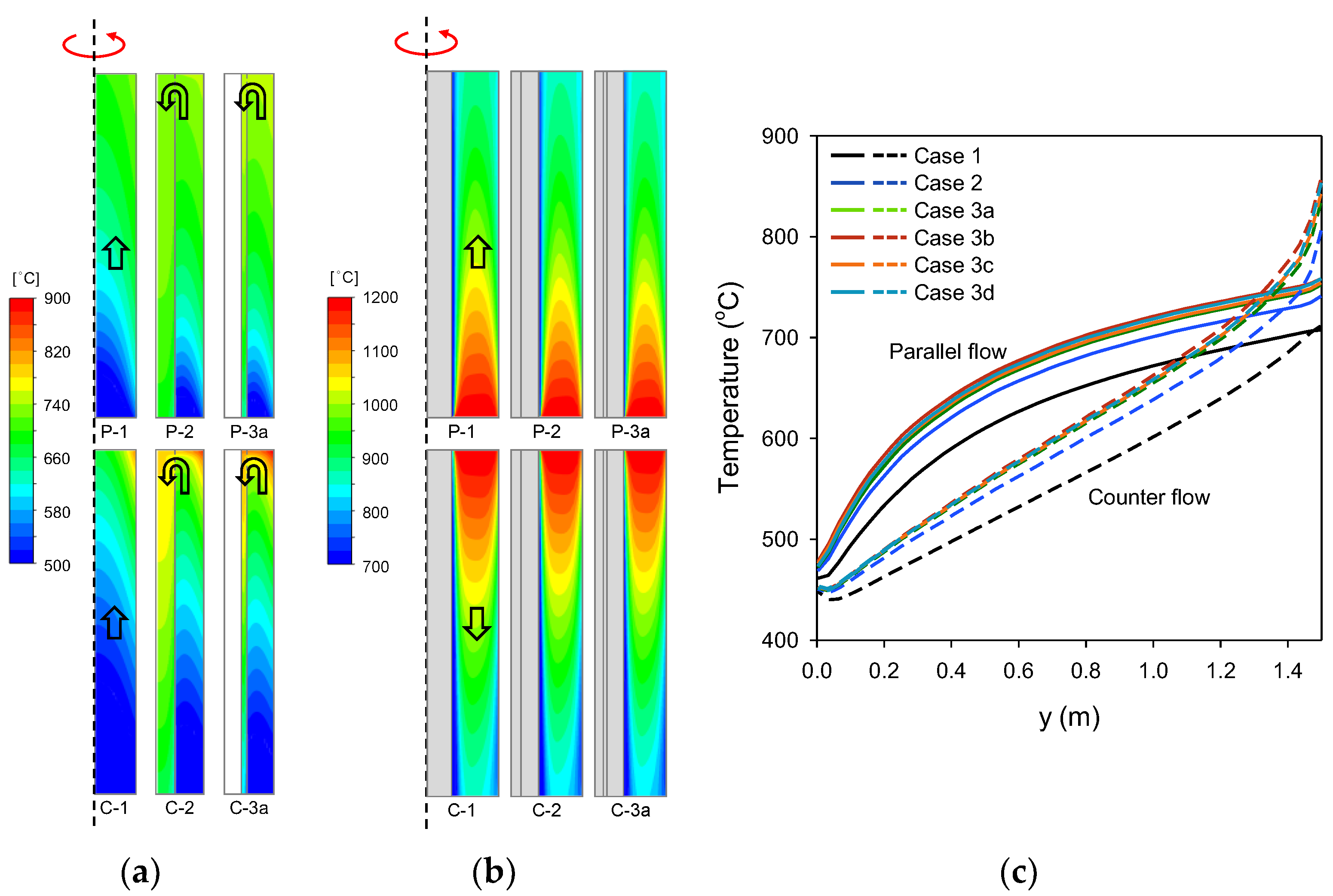
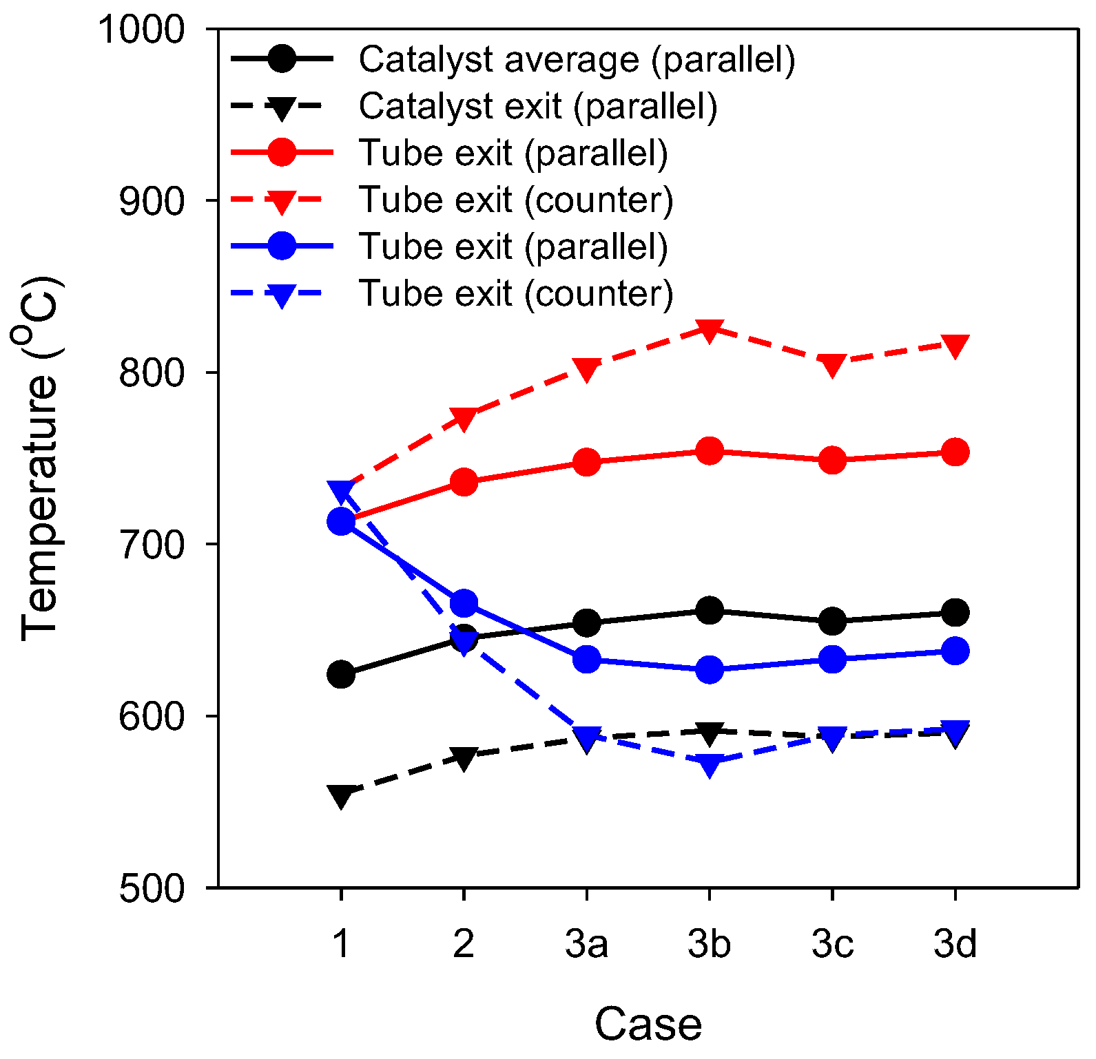
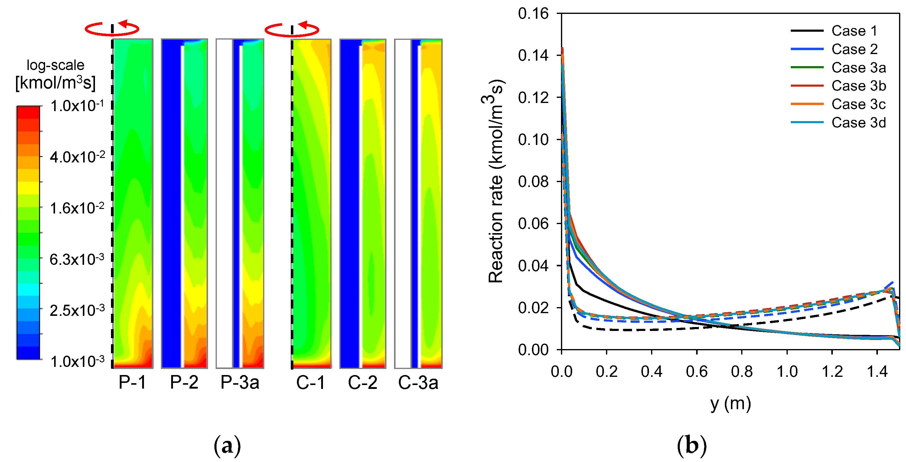
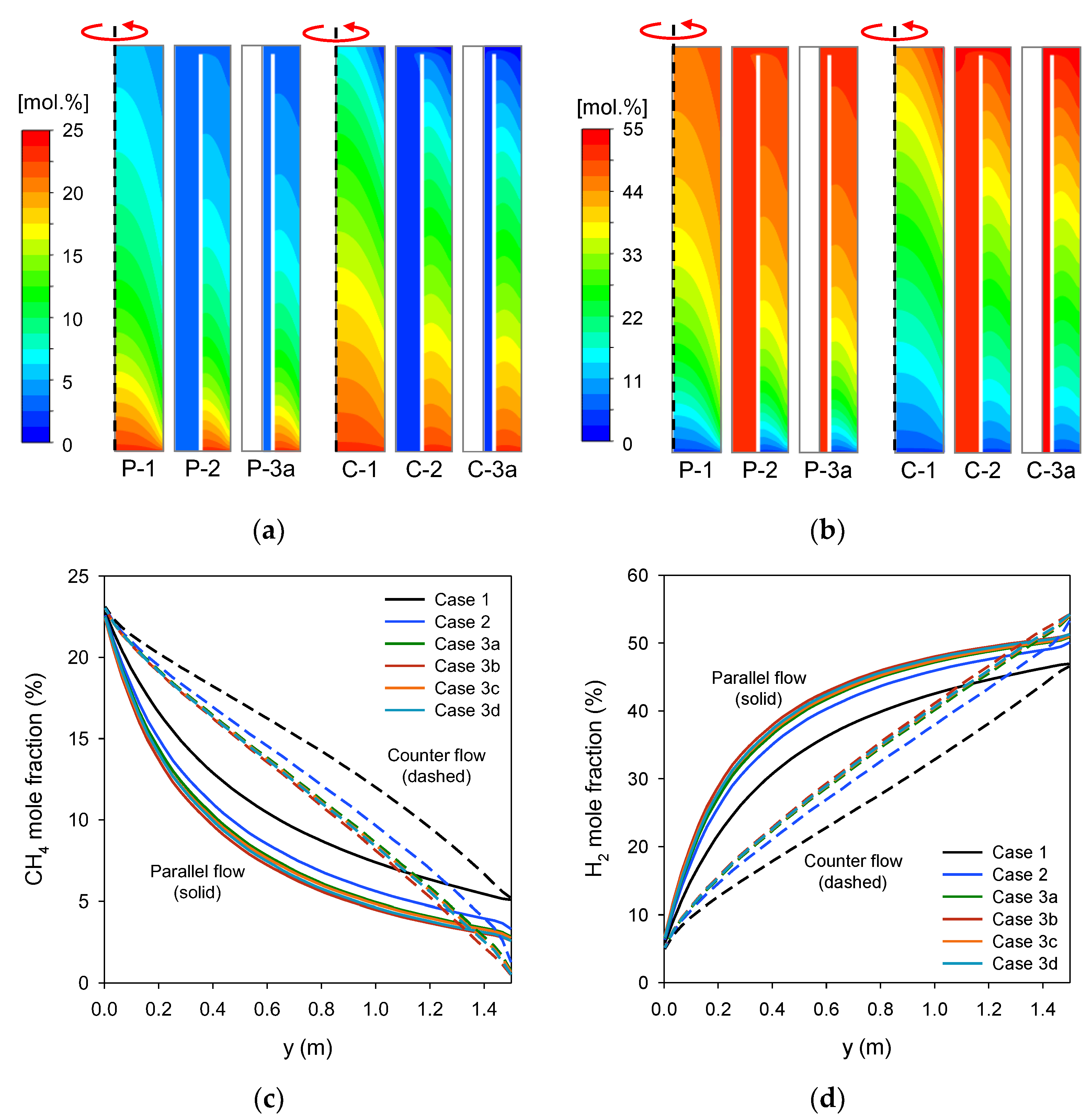
3.1. Analysis of Temperature and Methane Conversion

Figure 3a,b display the contours of the gas temperature within the reformer tube and the flue gas for the selected cases. As shown in Figure 3a, the gas temperature dropped rapidly by approximately 20–50 °C immediately upon entering the catalyst section due to rapid reforming reactions. With heat transfer occurring from the outer wall of the catalyst section, which comes in contact with the heat source, the gas temperature exhibited a parabolic profile in the radial direction and gradually increased toward the catalyst exit at the top. In the double and triple tubes, the reformate passing through the hollow inner core or annulus had higher temperatures than the outer catalyst section at the same height and acted as an additional heat source. Consequently, the reformate temperature gradually decreased towards the tube exit located at the bottom. The temperature contours were similar between the two flow configurations. However, the counter-flow configuration exhibited higher temperatures in the reformate. As shown in the contours of the flue gas temperature in Figure 3b, the temperature decreased at a slower rate in the parallel-flow cases.
Figure 3c displays the temperature profiles along the centerline of the catalyst section. The parallel-flow cases exhibited a rapid temperature increase in the early section, and this increase slowed down towards the catalyst exit. Conversely, the temperature increase in the counter-flow cases was steady throughout most of the catalyst section, accelerating towards the catalyst exit due to heat transfer from the hot flue gas. Consequently, the temperatures at the catalyst exit for the double and triple tubes in the counter-flow cases surpassed those of their respective parallel-flow cases. Among the tube designs, Cases 3a–3d exhibited similar temperature profiles, with Case 3b having the highest.
Figure 4 shows a comparison of three representative gas temperatures: (i) the volume-averaged temperature in the catalyst section (Tcat,avg), (ii) that of the reformate escaping the catalyst section (Tcat,exit), and (iii) that of the reformate leaving the tube (Ttube,exit). Tcat,avg was the lowest in single tubes, while the triple tubes with wider heating surfaces had higher values. Furthermore, the parallel-flow cases consistently had approximately 70 °C higher Tcat,avg than the counterflow cases. In contrast, the trend was reversed for Tcat,exit, with the counter-flow cases having 19–72 °C higher values. The highest value of Tcat,exit was 825.9 °C for Case C-3b. This was because the counter-flow cases exhibited a rapid temperature increase toward the exit of the catalyst section, as mentioned previously. Conversely, Ttube,exit exhibited the opposite trend to Tcat,exit, in which the counter-flow and triple-tube cases had lower values. The difference between the two temperatures (Ttube,exit–Tcat,exit) can be understood as the degree of heat transfer from the reformate in the inner core or annulus to the catalyst section. These results suggest that Case C-3b exhibited the highest heat transfer efficiency and methane conversion.
Figure 5 displays the methane conversion rate (sum of reaction rates [R1] and [R3]). In all cases, the methane conversion was rapid at the catalyst inlet due to the high CH4 concentration and slowed down as the gas progressed through the catalyst section. In the parallel-flow cases, the near-wall region close to the inlet maintained fast reaction rates owing to the heat supplied through the wall from the hot flue gas outside, whereas the reaction rate quickly decreased in the counter-flow cases. While the reaction rate in the parallel-flow cases decreased monotonously, the counter-flow cases had a gradual increase toward the exit because the temperature of the heat source became higher, as shown in Figure 5b. Regardless of the flow configuration, the single-tube designs exhibited the lowest reaction rates, whereas the triple-tube designs, particularly Case 3b, exhibited the highest values.
Figure 6 presents the contours and profiles of the CH4 and H2 mole fractions. The changes in the gas composition correspond to the reaction rates integrated from the inlet and, therefore, are not as steep as the reaction rates shown in Figure 5. The decrease in the CH4 mole fraction for the parallel-flow cases was rapid from the inlet but slowed down toward the exit. In contrast, the counterflow cases exhibited an almost linear decrease because the reactions continued at a significant rate throughout the catalyst section, as mentioned previously. For the H2 mole fraction, the trends were opposite to those observed for the CH4 mole fraction.
Figure 7 compares the methane conversion between the cases. The significant differences in methane conversion between the cases clearly demonstrate the importance of the reformer tube design for a compact SMR reactor. The counter-flow cases consistently exhibited higher methane conversion than the respective parallel-flow cases, whereas the double- and triple-tube cases performed better than the single-tube cases. In particular, Case C-3b, in a triple tube with a wider heating surface, had the highest conversion (94.5%), which was approximately 20% higher than the single-tube case. Compared to the plain triple tube of Case 3a, methane conversion was enhanced by 0.3% with internal fins (Case 3c) and by 1.3–1.6% with external fins (Case 3d). However, the impact was smaller than that in Case 3b, which had a larger tube diameter.
Compared to the representative temperatures (Figure 4), the methane conversion in Figure 7 exhibits a trend consistent with Tcat,exit rather than Tcat,avg. This implies that Tcat,exit has a more dominant effect on methane conversion than the temperature distribution inside the catalyst section. To analyze the influence of Tcat,exit on methane conversion, the H2 concentrations at chemical equilibrium at Tcat,exit and the actual values were compared, as shown in Figure 8. The results showed that the predicted H2 concentrations were very close to the equilibrium values. This is because after the active reactions in the early catalyst section, the methane conversion gradually approached chemical equilibrium toward the catalyst exit, and further conversion was restricted by the local temperatures represented by Tcat,exit. In the parallel-flow cases, the H2 concentrations were slightly above the equilibrium values because the near-wall temperatures at the catalyst exit were higher than the average value (Tcat,exit), resulting in additional methane conversion. These results suggest that installing a thermocouple near the catalyst exit can effectively monitor the performance of the reformer tube.

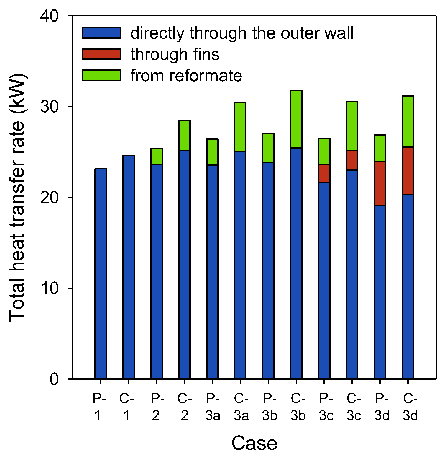
3.2. Analysis of Heat Transfer

The aforementioned differences in temperature and methane conversion between the tube designs are directly associated with heat transfer. Figure 9 depicts the profiles of total heat flux to the catalyst section through the outer wall facing the heat source and the inner wall facing the reformate flowing into the inner core or annulus. The heat flux from the heat source was dominated by convection while radiation accounted for 3.1–4.0% and 2.9–3.8% in the parallel- and counter-flow cases. In both flow configurations, Case 3d with external fins had the largest heat flux through the outer wall, followed by the single-tube design (Figure 9a). In the double- and triple-tube designs, the reformate in the internal core or annulus contributed additional heat to the catalyst section (Figure 9b). The double-tube design had a smaller heat flux, whereas the triple-tube design with external fins (Case 3d) had the largest heat flux. Notably, the outer and inner heating areas of the catalyst section were smaller in the single- and double-tube designs than in the triple-tube design.
Figure 10 presents the rate of heat transfer to the catalyst section via different paths, calculated by multiplying the surface area by the heat flux. The total heat transfer was more significant in the double- or triple-tube designs and in the counter-flow configuration. In the double- and triple-tube designs, the reformate acted as an additional heat source, providing 1.8–6.3 kW, which corresponded to 7.0–19.9% of the total heat transfer. Notably, the heat transfer from the reformate in the counter-flow configuration was greater than that in the parallel-flow configuration, which led to differences in the total heat transfer rate. This also resulted in the lowest temperature at which the reformate left the tube, as shown in Figure 4. Consequently, case C-3b, which had the largest inner and outer heating areas in the counter-flow configuration, had the highest heat transfer rate (31.8 kW), whereas case P-1 had the lowest (23.1 kW).
In Case 3c, with internal fins, the heat transfer from the heat source (through the wall and fins) was only 0.1 kW larger than that in Case 3a. This can be attributed to the minor differences in the thermal conductivity of the fin (23 W/m·K) and the effective thermal conductivity of the catalyst section. The increase in the heat transfer is due to the 1% larger surface area (A2o = 0.638 m2 for Case 3c compared to 0.631 m2 for Case 3a in Table 1) rather than heat transfer through fins. In contrast, the external fins in Case 3d exhibited better enhancement in heat transfer by 0.4–0.5 kW compared to Case 3a. This enhancement occurred because the heat transfer coefficient between the heat source and the outer tube wall, through convection and radiation, was smaller than the conduction through fins. Compared with the plain triple tube of Case 3a, A2o for Case 3b (0.688 m2 in Table 1) was 9% larger, while the heat transfer from the heat source increased by 3.3%. Conversely, Case 3d had the same A2o (ignoring the fins) but the heat transfer from the heat source increased by 3.8%. This suggests that external fins can be as effective as increasing the tube diameter depending on the design.
Heat transfer efficiency (η) was evaluated as a ratio between the heat absorbed by the reformate and the available enthalpy of the flue gas (heat source). The former is the sum of the enthalpy gain of the reformate and the total heat of the reaction, which is equivalent to the enthalpy loss of the flue gas.
η = H e x i t H i n r e f o r m a t e + Δ H r e a c t i o n H T s o u r c e , i n H T t u b e , i n s o u r c e = H e x i t H i n s o u r c e H T s o u r c e , i n H T t u b e , i n s o u r c e
As shown in Figure 11, η for the counter-flow cases was in the range of 53.9−59.5%, which was approximately 7% higher than the respective cases with parallel-flow configuration. The differences between the cases were not as large as those for methane conversion (Figure 7), suggesting the importance of enhancing the heat transfer.

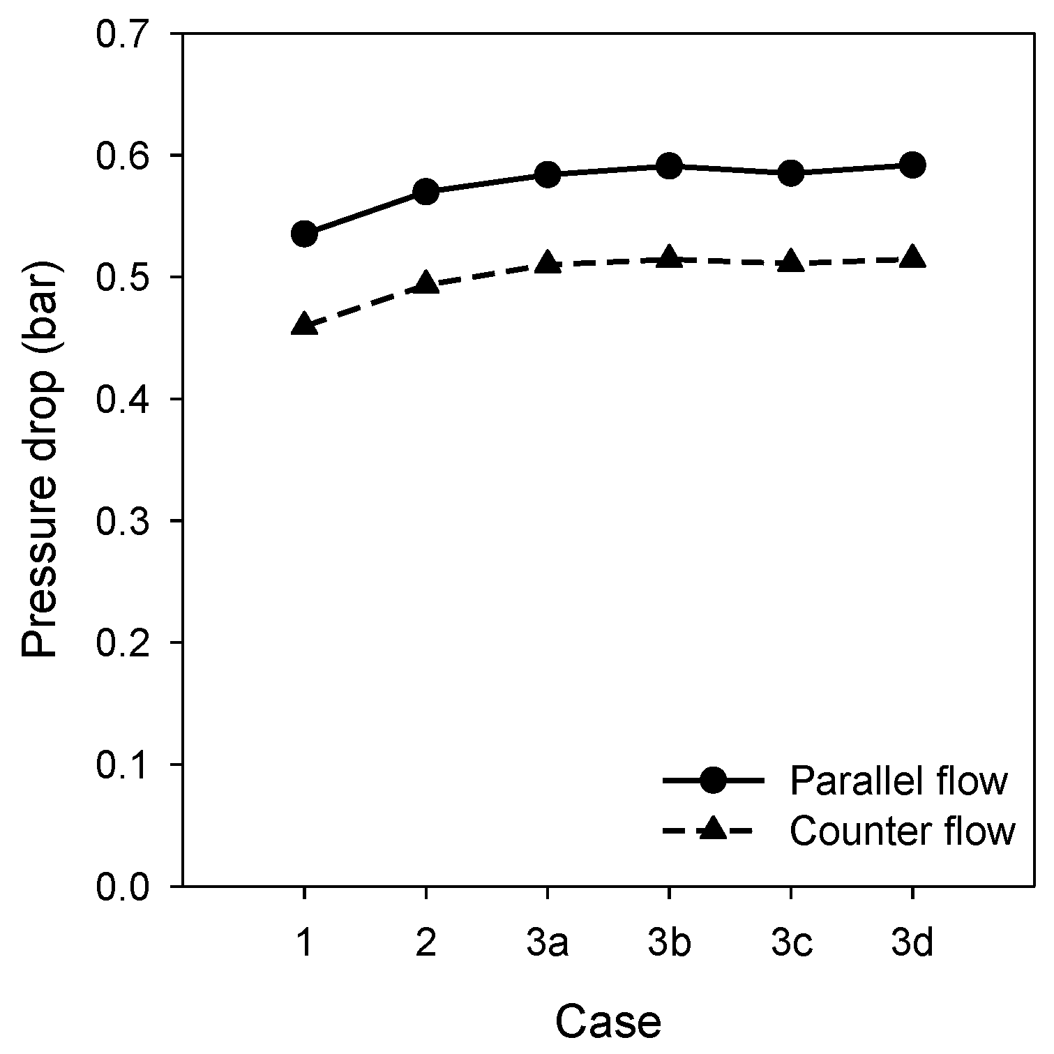
3.3. Pressure Drop in the Reformer Tube

Figure 12 illustrates the pressure drop in the reformer tube for different reformer tube designs and flow configurations. The pressure drop was approximately 0.5 bar, and the differences between cases were not significant. It is lower in the counter-flow and single-tube cases, which is consistent with the average temperature in the catalyst section (Tcat,avg) presented in Figure 4. This is because the pressure loss increases with the gas velocity, which is dominated by the temperature, as given in the Ergun equation in Section 2.2. For the double- or triple-tube designs, the pressure loss inside the inner core or annulus was less than 0.006 bar; therefore, its contribution was insignificant. The results suggest that the counter-flow configuration is favorable for reducing pressure loss and increasing methane conversion.

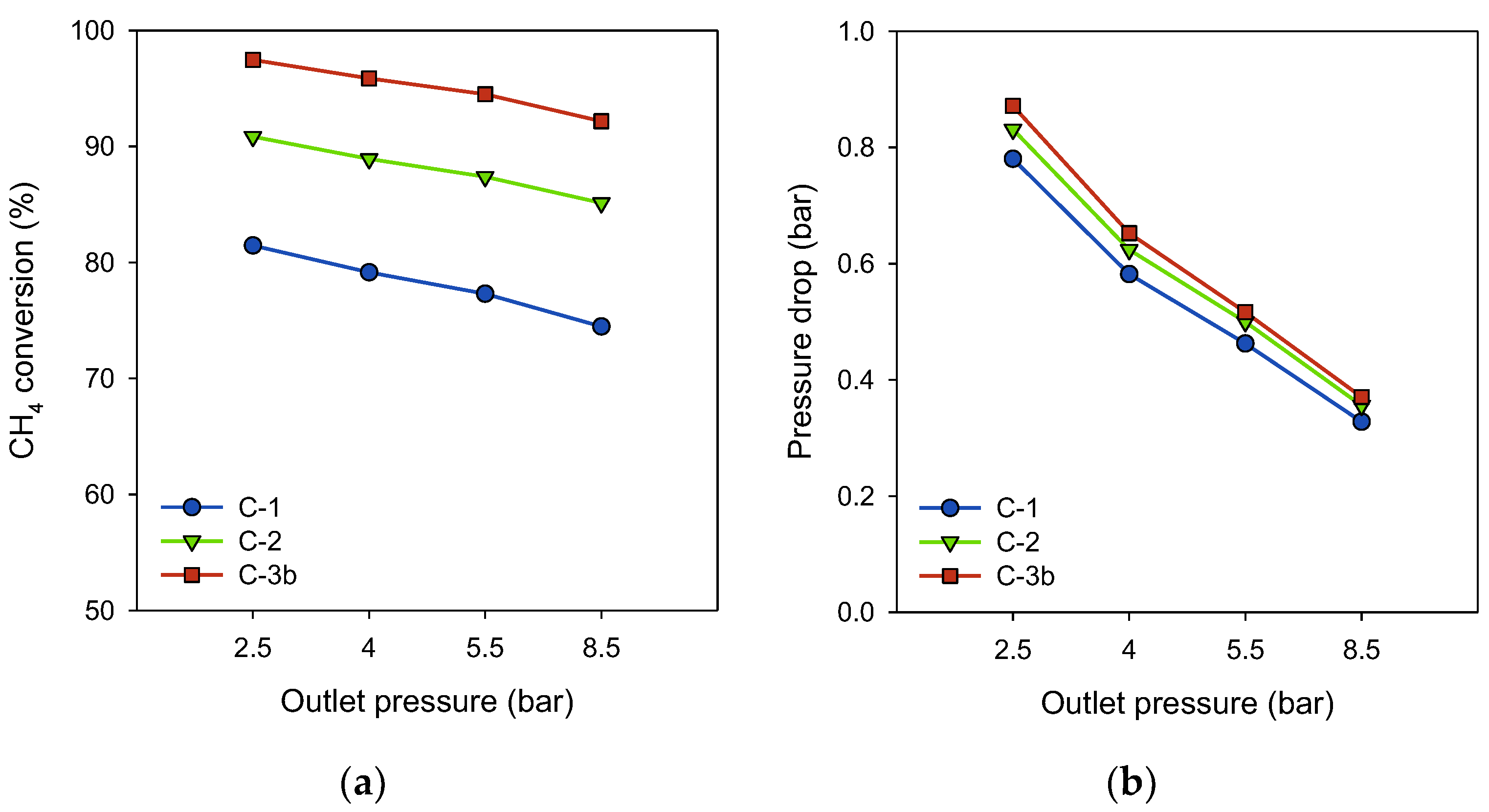
3.4. Influence of Reformate Pressure on Methane Conversion and Pressure Loss

Figure 13 shows the methane conversion and pressure loss when the pressure of the reformate was varied for the selected counter-flow cases. Methane conversion increased at lower pressures, mainly because the chemical equilibrium shifted towards the reactant side with an increase in the number of moles in the products. Although Case C-1, which had a lower methane conversion, was more sensitive to pressure, the large differences between the cases were maintained. This suggests that a reformer design employing a triple tube can maximize the methane conversion regardless of the reaction conditions. However, the pressure loss increased rapidly at lower pressures and was inversely proportional to the gas velocity. The higher methane conversion also increased the gas velocity by a larger number of moles in the products, but its contribution to the pressure loss was not significant because the differences between the cases were small at the same pressure, as shown in Figure 13b.

4. Conclusions

This study evaluated the performance of various reformer tube designs and flow configurations in terms of the methane conversion and heat transfer efficiency of a compact SMR. Using CFD, the reactions, heat transfer, and pressure loss in the reformer tubes were analyzed in detail under identical reaction conditions and catalyst volumes. The double- and triple-tube designs outperformed the single-tube design, exhibiting significantly higher methane conversion and heat transfer efficiencies. This improvement was due to the larger wall area facing the heat source and additional heat recovery from the reformate flowing in the inner core or annulus. These factors led to the highest temperature at the catalyst exit and the lowest temperature of the reformate at the reformer tube exit, which can also benefit subsequent water–gas shift reaction processes. In addition to increasing the tube diameter of the triple tube, installing external fins facing the heat source was more effective for further enhancement of the heat transfer than internal fins in the catalyst section. The pressure loss exhibited trends similar to those of the average temperature in the catalyst section, with the difference between the tube designs being less significant than those between the two flow configurations. Increasing the reformate pressure lowers methane conversion, but the pressure loss decreases rapidly with reduced gas velocity. The trends in methane conversion for the various tube designs remained consistent across different pressures. In all cases, the methane conversion closely approached the chemical equilibrium at the catalyst exit, suggesting that installing a thermocouple near the catalyst exit could serve as an effective method for monitoring reformer performance.
In practical applications, SMRs often employ multiple reformer tubes, with complex flow configurations of the hot flue gas. The arrangement of individual reformer tubes can be optimized by evaluating the methane conversion, peak temperature, and heat transfer rate using CFD.

Author Contributions

Methodology, Y.K.; Validation, Y.K.; Formal Analysis, Y.K. and S.K.; Writing—Original Draft, Y.K.; Writing—Review and Editing, C.R.; Project Administration, H.R. and S.Y.; Funding Acquisition, C.R. All authors have read and agreed to the published version of the manuscript.

Funding

This work was supported by the Technology Innovation Program (Development and demonstration of 2 ton/hr industrial hydrogen boiler, 20023380) funded By the Ministry of Trade, Industry & Energy (MOTIE, Korea). This research was supported by the Sungkyunkwan University and the BK21 FOUR (Graduate School Innovation) funded by the Ministry of Education (MOE, Korea) and National Research Foundation of Korea (NRF).

Data Availability Statement

The data presented in this study are available on request from the corresponding author.

Conflicts of Interest

The authors declare no conflict of interest.

Nomenclature

SymbolsGreek
AArea (m2) γ Porosity of catalyst
CModel constant ε Rate of dissipation
DDiameter (mm) η Heat transfer efficiency
DpParticle size of catalyst (mm) μ Viscosity (kPa·s)
GGeneration of turbulence kinetic energy v Gas superficial velocity (m/s)
kTurbulence kinetic energy ρ Density of porous media (kg/m3)
kiRate coefficient of reaction i(kmol, bar, kgcat, h) σ Turbulent Prandtl number
KiEquilibrium constant for reaction i
KCH4, KCO, KH2Adsorption constant (bar−1)Subscripts
KH2ODissociative adsorption constantavgAverage
LDepth of porous media (m)bBuoyancy
MMolecular weightcatCatalyst
Δ P Pressure drop (kPa)exitExit
pPartial pressure (bar)iIndex of reforming reaction
riRate of reaction i (kmol/kgcat·h)tTurbulence
TTemperature (°C)tubeReforming tube
uVelocity (m/s)
xMass fraction

References

  1. Staffell, I.; Scamman, D.; Abad, A.V.; Balcombe, P.; Dodds, P.E.; Ekins, P.; Shah, N.; Ward, K.R. The role of hydrogen and fuel cells in the global energy system. Energy Environ. Sci. 2019, 12, 463–491. [Google Scholar] [CrossRef]
  2. Younas, M.; Shafique, S.; Hafeez, A.; Javed, F.; Rehman, F. An overview of hydrogen production: Current status, potential, and challenges. Fuel 2022, 316, 123317. [Google Scholar] [CrossRef]
  3. Birol, F. The Future of Hydrogen: Seizing Today’s Opportunities; International Energy Agency: Paris, France, 2019; Available online: https://doi.org/10.1787/1e0514c4-en (accessed on 18 June 2019).
  4. Chen, L.; Qi, Z.; Zhang, S.; Su, J.; Somorjai, G.A. Catalytic hydrogen production from methane: A review on recent progress and prospect. Catalysts 2020, 10, 858. [Google Scholar] [CrossRef]
  5. Ogden, J.M. Review of Small Stationary Reformers for Hydrogen Production; IEA/H2/TR-02/002; International Energy Agency: Paris, France, 2001. [Google Scholar]
  6. Zhao, X.; Joseph, B.; Kuhn, J.; Ozcan, S. Biogas reforming to syngas: A review. IScience 2020, 23, 101082. [Google Scholar] [CrossRef]
  7. Barbarias, I.; Lopez, G.; Artetxe, M.; Arregi, A.; Bilbao, J.; Olazar, M. Valorisation of different waste plastics by pyrolysis and in-line catalytic steam reforming for hydrogen production. Energy Convers. Manag. 2018, 156, 575–584. [Google Scholar] [CrossRef]
  8. Nobandegani, M.S.; Birjandi, M.R.S.; Darbandi, T.; Khalilipour, M.M.; Shahraki, F.; Mohebbi-Kalhori, D. An industrial Steam Methane Reformer optimization using response surface methodology. J. Nat. Gas Sci. Eng. 2016, 36, 540–549. [Google Scholar] [CrossRef]
  9. Yuan, Q.; Gu, R.; Ding, J.; Lu, J. Heat transfer and energy storage performance of steam methane reforming in a tubular reactor. Appl. Therm. Eng. 2017, 125, 633–643. [Google Scholar] [CrossRef]
  10. Li, P.; Chen, L.; Xia, S.; Zhang, L. Maximum hydrogen production rate optimization for tubular steam methane reforming reactor. Int. J. Chem. React. Eng. 2019, 17, 20180191. [Google Scholar] [CrossRef]
  11. Jo, T.; Koo, B.; Lee, Y.; So, H.; Lee, D. Numerical and experimental study on the thermal characteristics of a steam reformer. J. Mech. Sci. Technol. 2018, 32, 679–687. [Google Scholar] [CrossRef]
  12. Yeh, C.L. Numerical investigation of the effects of steam mole fraction and the inlet velocity of reforming reactants on an industrial-scale steam methane reformer. Energies 2018, 11, 2082. [Google Scholar] [CrossRef]
  13. Rosen, M.A. Thermodynamic investigation of hydrogen production by steam-methane reforming. Int. J. Hydrogen Energy 1991, 16, 207–217. [Google Scholar] [CrossRef]
  14. Peng, X.D. Analysis of the thermal efficiency limit of the steam methane reforming process. Ind. Eng. Chem. Res. 2012, 51, 16385–16392. [Google Scholar] [CrossRef]
  15. Hajjaji, N.; Pons, M.N.; Houas, A.; Renaudin, V. Exergy analysis: An efficient tool for understanding and improving hydrogen production via the steam methane reforming process. Energy Policy 2012, 42, 392–399. [Google Scholar] [CrossRef]
  16. De Falco, M.; Santoro, G.; Capocelli, M.; Caputo, G.; Giaconia, A. Hydrogen production by solar steam methane reforming with molten salts as energy carriers: Experimental and modelling analysis. Int. J. Hydrogen Energy 2021, 46, 10682–10696. [Google Scholar] [CrossRef]
  17. Shagdar, E.; Lougou, B.G.; Shuai, Y.; Ganbold, E.; Chinonso, O.P.; Tan, H. Process analysis of solar steam reforming of methane for producing low-carbon hydrogen. RSC Adv. 2020, 10, 12582–12597. [Google Scholar] [CrossRef] [PubMed]
  18. Engel, S.; Liesche, G.; Sundmacher, K.; Janiga, G.; Thévenin, D. Optimal tube bundle arrangements in side-fired methane steam reforming furnaces. Front. Energy Res. 2020, 8, 583346. [Google Scholar] [CrossRef]
  19. Shin, G.; Yun, J.; Yu, S. Thermal design of methane steam reformer with low-temperature non-reactive heat source for high efficiency engine-hybrid stationary fuel cell system. Int. J. Hydrogen Energy 2017, 42, 14697–14707. [Google Scholar] [CrossRef]
  20. Yun, J.; Kim, Y.; Yu, S. Interactive heat transfer characteristics of 5 kW class shell-and-tube methane steam reformer with intermediate temperature heat source. Int. J. Hydrogen Energy 2020, 45, 21767–21778. [Google Scholar] [CrossRef]
  21. Rohini, A.K.; Choi, S.H.; Lee, H.J. Numerical parametric study on the burner arrangement design for hydrogen production in a steam methane reformer. Int. J. Energy Res. 2021, 45, 16006–16026. [Google Scholar] [CrossRef]
  22. Halder Topsoe. Bayonet Reformer (SMR-b). Available online: https://www.topsoe.com/our-resources/knowledge/our-products/equipment/bayonet-reformer-smr-b (accessed on 4 October 2023).
  23. Ma, T.; Zeng, M.; Ji, Y.; Zhu, H.; Wang, Q. Investigation of a novel bayonet tube high temperature heat exchanger with inner and outer fins. Int. J. Hydrogen Energy 2011, 36, 3757–3768. [Google Scholar] [CrossRef]
  24. Gao, Q.; Zhang, P.; Peng, W.; Chen, S.; Zhao, G. Structural design simulation of bayonet heat exchanger for sulfuric acid decomposition. Energies 2021, 14, 422. [Google Scholar] [CrossRef]
  25. Lee, J.; Cho, H.; Kim, M.; Hall, S.; Moon, I. Double-tube reactor design and process optimization for on-site steam methane reforming processes. Ind. Eng. Chem. Res. 2020, 59, 18028–18038. [Google Scholar] [CrossRef]
  26. Minette, F.; De Almeida, L.C.; Feinstein, J.; De Wilde, J. Structured ZoneFlow™-Bayonet steam reforming reactor for reduced firing and steam export: Pressure drop and heat transfer modelling and evaluation of the reactor performance. Chem. Eng. J. Adv. 2022, 10, 100258. [Google Scholar] [CrossRef]
  27. Upadhyay, M.; Lee, H.; Kim, A.; Lee, S.H.; Lim, H. CFD simulation of methane steam reforming in a membrane reactor: Performance characteristics over range of operating window. Int. J. Hydrogen Energy 2021, 46, 30402–30411. [Google Scholar] [CrossRef]
  28. Lao, L.; Aguirre, A.; Tran, A.; Wu, Z.; Durand, H.; Christofides, P.D. CFD modeling and control of a steam methane reforming reactor. Chem. Eng. Sci. 2016, 148, 78–92. [Google Scholar] [CrossRef]
  29. ANSYS Inc. ANSYS Fluent User Guide; ANSYS Inc.: Cannonsburg, PA, USA, 2016. [Google Scholar]
  30. Xu, J.; Froment, G.F. Methane steam reforming, methanation and water-gas shift: I. Intrinsic kinetics. AIChE J. 1989, 35, 88–96. [Google Scholar] [CrossRef]
  31. Wesenberg, M.H.; Svendsen, H.F. Mass and heat transfer limitations in a heterogeneous model of a gas-heated steam reformer. Ind. Eng. Chem. Res. 2007, 46, 667–676. [Google Scholar] [CrossRef]
  32. Launder, B.E.; Spalding, D.B. Lectures in Mathematical Models of Turbulence; Academic Press: London, UK, 1972. [Google Scholar]
  33. Smith, T.F.; Shen, Z.F.; Friedman, J.N. Evaluation of coefficients for the weighted sum of gray gases model. J. Heat Transf. 1982, 104, 602–608. [Google Scholar] [CrossRef]
Figure 1. Schematic of various reformer tube designs.
Energies 16 07475 g001
Figure 2. Validation of numerical model for SMR using the literature data [28]: (a) profiles of wall temperatures and (b) H2 mole fraction.
Energies 16 07475 g002
Figure 3. Gas temperature distribution for different tube designs: (a) contours in the reformer tube, (b) contours in flue gas (heat source), and (c) profiles along the centerline of the catalyst section.
Energies 16 07475 g003
Figure 4. Average temperatures for the catalyst section and reformed gas escaping the catalyst.
Energies 16 07475 g004
Figure 5. Methane conversion rate: (a) contours for selected cases and (b) profiles along the centerline of the catalyst section.
Energies 16 07475 g005
Figure 6. Gas mole fractions: contours of (a) CH4 and (b) H2 for selected cases and profiles along the centerline of the catalyst section for (c) CH4 and (d) H2.
Energies 16 07475 g006
Figure 7. Methane conversion for different reformer tube designs.
Energies 16 07475 g007
Figure 8. Comparison of H2 concentration between the chemical equilibrium at Tcat,exit and simulation results at the catalyst exit.
Energies 16 07475 g008
Figure 9. Profiles of total heat flux to the catalyst section through the (a) outer wall facing the heat source and (b) inner wall facing the reformate.
Energies 16 07475 g009
Figure 10. Rate of total heat transfer to the catalyst and contribution of different heat transfer paths.
Energies 16 07475 g010
Figure 11. Heat transfer efficiency for different reformer tube designs in parallel- and counter-flow configurations.
Energies 16 07475 g011
Figure 12. Pressure loss in catalyst for different reformer tube designs in parallel- and counter-flow configurations at tube exit pressure of 6.5 bar.
Energies 16 07475 g012
Figure 13. Influence of pressure on (a) methane conversion and (b) pressure loss for selected cases.
Energies 16 07475 g013
Table 1. Specification of different reformer tube designs.
Case123a3b3c3d
Diameter (mm)D1331331331331331331
D2o115.1129.7133.9145.9135.3133.9
D2i96.4111.0115.2127.2116.6115.2
D3o-5563836363
D3i 55755555
D4--40604040
Fin thickness (mm)----55
Outer surface area, A2o (m2)0.5420.6110.6310.6880.6380.631
Height (mm)1500
Catalyst cross-sectional area (mm2)7300
Table 2. Operating conditions of the reformer.
Operating ConditionValue
Reforming gasInlet temperature (°C)500
Tube exit pressure (bar, abs)6.5 (2.5–8.5)
Mass flow rate (kg/s)0.0084
Steam-to-carbon ratio3
Heat sourceInlet temperature (°C)1200
Pressure (bar, abs)1
Mass flow rate (kg/s)0.0328
Composition (mol.%)9.6% O2, 10.9% CO2, 12.4% H2O, and 67.1% N2
Table 3. Boundary conditions for the walls of the reformer.
WallParameterValue
Outer wall of heat sourceHeat transferAdiabatic
Emissivity0.7
Reformer tubeEmissivity0.65
Thermal conductivity (W/m·K)23
Disclaimer/Publisher’s Note: The statements, opinions and data contained in all publications are solely those of the individual author(s) and contributor(s) and not of MDPI and/or the editor(s). MDPI and/or the editor(s) disclaim responsibility for any injury to people or property resulting from any ideas, methods, instructions or products referred to in the content.

