Article

Performance Evaluation of a Steam Ejector Considering Non-Equilibrium Condensation in Supersonic Flows

1
School of Mechanical and Electrical Engineering, Chuzhou University, Chuzhou 239000, China
2
State Key Laboratory of Fire Science, University of Science and Technology of China, Hefei 230026, China
3
School of Mechanical Engineering & Automation, Northeastern University, Shenyang 110819, China
4
Faculty of Environment, Science and Economy, University of Exeter, Exeter EX4 4QF, UK
*
Authors to whom correspondence should be addressed.
Energies 2023, 16(23), 7755; https://doi.org/10.3390/en16237755
Submission received: 13 July 2023 / Revised: 4 November 2023 / Accepted: 13 November 2023 / Published: 24 November 2023
(This article belongs to the Topic Advanced Heat and Mass Transfer Technologies)

Abstract

:
The present study established an experimental system of steam ejector refrigeration to evaluate the effect of the operating parameters, such as pressure on the diffuser wall and primary and secondary fluid, on the performance and efficiency of the ejector. The model validation of numerical methods was carried out against the experimental data, while the numerical simulation was conducted by utilizing computational fluid dynamics modeling to analyze the internal flow of the ejector. The results indicated that the escalation of the primary steam pressure in the choking position increased the Mach number and entrainment ratio as the flow area of the secondary fluid remained constant. The optimization studies show that the entrainment ratio was maximum when the primary steam pressure was 0.36 MPa. While the pressure was inordinate, the expansion core increased in size and further compressed the flow area of the secondary fluid, hence reducing the entrainment ratio. Subject to the influence of the normal shockwave, the change in back pressure did not alter the entrainment ratio before the critical back pressure. In contrast, the ejector no longer produces the normal shockwave after the critical back pressure; the entrainment ratio, therefore, was reduced with the increase in back pressure.

1. Introduction

The global energy crisis has surged, with the world encountering energy shortages since 2021. This leads to the exploitation of equipment that utilizes industrial waste heat or solar energy, such as steam ejector refrigeration systems [1,2], to minimize energy waste. The steam ejector can minimize energy waste as it only requires a small amount of energy for its activation [3,4,5]. Recently, the steam ejector refrigeration system gained much research attention because of its capability to recycle working fluid to generate a second flow stream. The heat exchanges occurred between the second stream and the evaporator, thereby consistently cooling down the evaporator with the continuous flow of the second stream [6,7,8].
Numerical simulation has proven to be the most reliable method for simulating fluid flow inside an ejector. It can accurately predict and evaluate various flow phenomena that occur during fluid flow, such as shock waves, mixing, boundary layers, phase changes, compressibility, supersonic flow, and complex flows. Many researchers use this powerful simulation method to gain a deeper understanding of the hydrodynamic behavior of ejectors, allowing them to better design and optimize ejectors. Furthermore, careful choice of a turbulence model is required in choosing an appropriate physical model to define the problem. Numerical settings and discretization schemes should also be handled appropriately to obtain stable and convergent solutions. Debonis [9] and Kim [10] et al. obtained better visualization effects through CFD analysis of the local flow inside the ejector, which proved that this method has good application prospects in the numerical simulation of the ejector and is considered to be an effective way to optimize ejectors.
Sriveerakul et al. [11] studied the effects of different working fluid pressures on the internal flow structure and fluid mixing process of steam ejectors. The research results show that there are two different types of oblique shock wave structures in the internal flow of the ejector. The increase in condenser pressure will cause the position of the normal shock wave to move upstream into the equal-area mixing section of the ejector and affect the congestion of the ejector mixing process. Pianthong et al. [12] studied the influence of operating conditions on the internal flow phenomena and overall performance of steam ejectors using the CFD method. Wang and Dong [13] used the realizable k-ε turbulence model to study the mixing behavior of the working fluid and ejection fluid in a steam ejector. Sharifi and Boroomand [14] used the realizable k-ε turbulence model to study the fluid flow pattern inside the ejector. They applied two numerical schemes based on axial symmetry and three-dimensional assumptions to analyze the performance-influencing parameters of the ejector and compared the results with experimental measurements. Lei et al. [15] studied the wet steam model to optimize ejector geometry. The research results indicated that when compared to the conventional dry gas model, the use of the wet steam model dramatically decreases the entrainment ratio error from 16.24% for single-phase steam to 3.92% when compared to experimental data. Existing research results show that the axisymmetric model is able to predict similar results to the 3D model, and both agree with the experimental data within 10%.
At the current stage of research, most research papers that use CFD methods to simulate ejectors lack verification of the CFD model. Although a few articles have verified the model, there is a problem of insufficient verification. At the same time, due to the low computing power of early computers, numerical simulation using fine meshes became time-consuming and laborious. In recent years, the improvement in computing power and the continuous development of numerical tools have led to more innovations and a deeper understanding of CFD theory, making CFD more widely used and attracting the attention of more and more researchers. This allows people to have a better understanding of the overall operation and local flow characteristics of the ejector under different operating conditions, geometries, and working fluids, making the design and optimization of the ejector easier and making it easier to conduct research.
The working of the ejector involved the choking flow, which was defined as the fluid dynamics associated with certain pressure passing through the constriction into a low-pressure environment, and its speed or velocity was greatly boosted [16,17]. A convergent–divergent nozzle, which is also known as the Laval nozzle, is the main component. The structure and the internal flow behavior of the steam ejector are presented in Figure 1 [18]. The internal flow is complex and involves a transonic flow behavior: the primary fluid (steam) that passes through the Laval nozzle will increase in speed from a stagnation state to a supersonic state, creating a low-pressure (vacuum) environment in the mixing chamber. The secondary fluid enters the mixing chamber due to the pressure difference, further demonstrating extreme energy and momentum exchange with the high-speed primary fluid. Lastly, the speed of both fluids is reduced to subsonic and increases in pressure within the diffuser, further exhausting to the atmosphere or extracted by the primary pump.
A recent analysis of the steam ejector’s internal flow and heat transfer provided crucial data as references to improvise the design structure of the steam ejector [7,19,20]. It was agreed in many studies that the optimization of design structures accounted for the parameters of the choking flow [21,22,23]. In particular, Rand et al. [24] confirmed that the choking criteria and Mach number were the parameters used in determining the nozzle head exit position. Kang et al. [25] claimed that the choking flow [26,27,28] was critically accommodated by the pressure of the fluid caused by the geometries and inflow conditions on ejector operations. Nonetheless, the limited experimental data in past research resulted in a lack of supportive results on the theoretically designed ejector model, thereby restricting the publicization of the simulation results and their applicability.
The cooling coefficient COP (coefficient of performance) of a steam ejector is [16]:
C O P = m s ( h e , 0 h e , i ) m p ( h g , 0 h g , i )
For the ejector itself, the criterion for describing its efficiency is the entrainment ratio, ER [29]:
E R = m s m p
C O P = E R ( h e , 0 h e , i ) ( h g , 0 h g , i )
where mp represents the primary flow rate, and ms represents the secondary flow rate.
In the above analysis and derivation of the formula, ER is the main influencing factor of COP, and thus, it is also the main factor affecting the whole cooling cycle.
In recent years, the development of numerical simulation-based techniques has allowed for a more detailed study of the flow field and the fluid mixing within the ejector, leading to a rational design of the ejector configuration and structure [17,30]. Previous work only focused on the nozzle localization, while the overall ejector process is not well interpreted [31]. CFD numerical calculations can provide more detailed information and comprehensively portray the heat–liquid coupling process in high-temperature chemical reaction processes, which is difficult to obtain through experimental analysis.
Both experimental research and numerical simulation research are time-consuming, laborious, and require large cost support. Therefore, it is necessary to find a suitable and reasonable method to optimize the ejector structure. The current research on ejectors is still based on experiments and numerical simulations, and numerical simulations need to be based on the verification of existing experimental data, which reduces the research efficiency of ejectors. If a method that can comprehensively consider the impact of various factors on ejector performance can be found based on ejector experimental data or numerical simulation results, it will greatly reduce and shorten the ejector design improvement cycle and improve the ejector optimization process.
In this work, a comprehensive analysis was conducted on the choked flow under spontaneous condensation of steam and its effect on the ejector entrainment ratio. The main contributions of this study include:
(1)
We established an experimental system for the steam ejector refrigeration cycle to provide an experimental reference for numerical calculation and analysis;
(2)
We developed a numerical model of the ejector under wet steam conditions and verified the veracity and validity of the numerical model by comparing it with experimental data;
(3)
We studied the flow of the effective area, expansion nuclei, and excitation waves inside the ejector under the flow of choking flow and the effect on the induced coefficient of the ejector and then discussed the law of the influence of the choked flow on the priming coefficient at different operating and pumped gas pressures;
(4)
We investigated the importance of choked flow in preventing backflow at the outlet, improved and optimized the operating conditions of the ejector, and analyzed the performance improvement of the ejector under different choking flows.

2. Experimental Systems

2.1. Experimental Setup

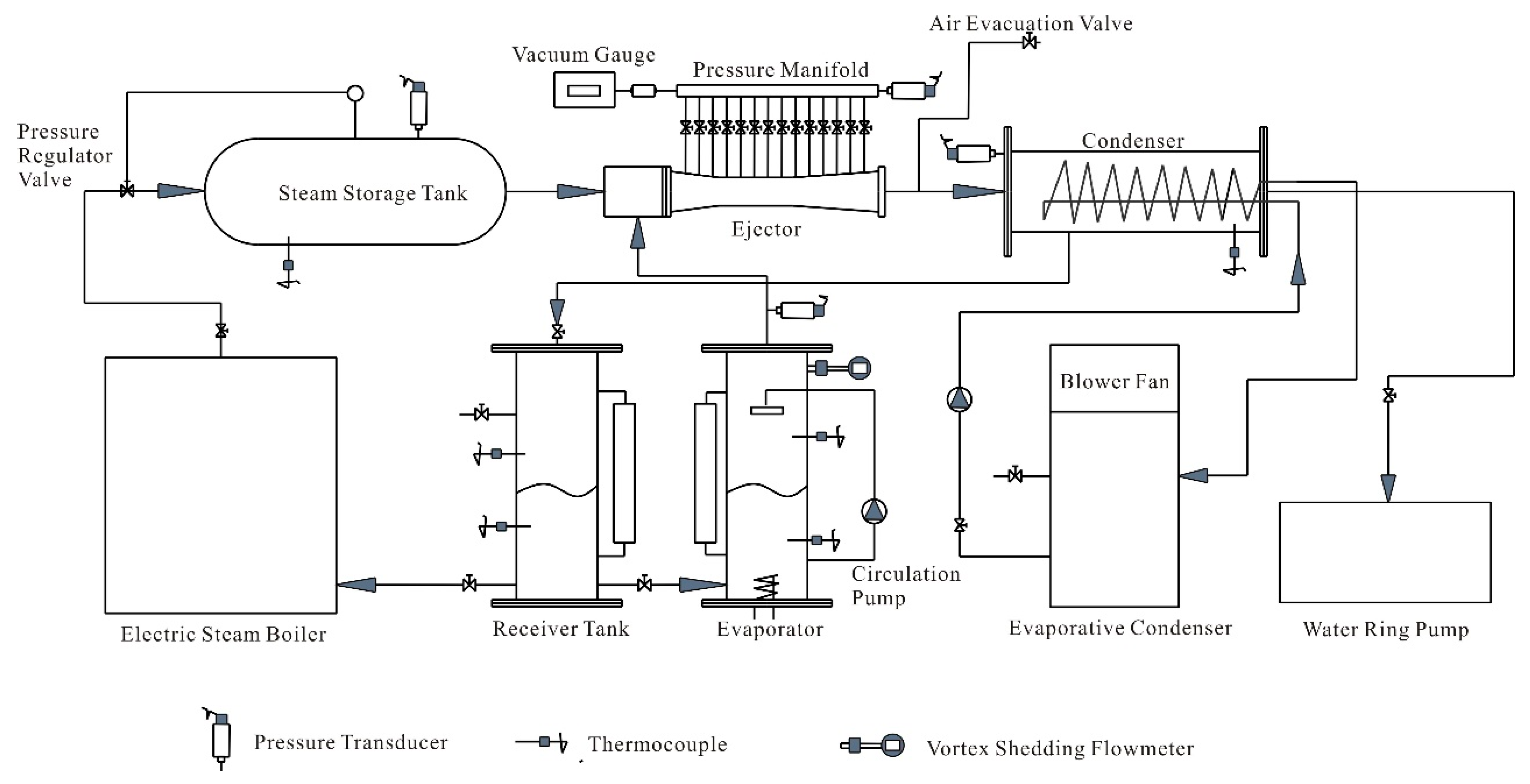
Figure 2 presents the experimental setup of the steam ejector refrigeration system, which is composed of a steam ejector, a snake-like tube condenser, storage tanks, a boiler, an evaporator, a water pump, a pressure regulator valve, a vacuum gauge, and other components.
The saturated steam with a certain pressure served as the primary fluid produced by the boiler. The primary fluid was stored in the steam storage tank, and the degree of the primary fluid pressure was controlled with the pressure regulator valve to suit the experiment operation conditions. The water ring pump serves as a primary pump, providing consistent outlet pressure to ensure steady conditions by coupling the condenser with the outlet ejector. The storage tank is equipped with temperature and pressure sensors, providing a buffering effect that secures the sustainability and stability of the primary fluid. While the secondary fluid is the steam produced by the evaporator, its flow is measured and governed by the vortex flowmeter. The temperature control of the secondary fluid in the evaporator was performed with the aid of a thermostat.
The primary fluid entered the Laval nozzle through the storage tank and generated a low-pressure area at the outlet section of the nozzle. The heating of the water in the evaporator produced water vapor. As the pressure in the evaporator was lower than the pressure at the outlet section, the water vapor, which is also known as secondary fluid, was channeled away from the evaporator, thereby providing a cooling effect to reduce the temperature in the evaporator. The formation of the expansion core subject to the primary fluid entering the mixing chamber had drawn the secondary fluid into the mixing chamber and concurrently accelerated the flow of the fluids. The mixing was finished when both primary and secondary fluids reached the end of the mixing chamber. The cycle came to an end when the mixed fluids were discharged from the diffuse and entered the condenser.
The water condensate was heated to a certain temperature controlled with a temperature control relay in the condenser. The water was pumped to the sprinkler located at the top of the evaporator by using a small circulating pump and sprayed out at low pressure. Subject to the temperature in the evaporative condenser being higher than the boiling point of the water, the water droplets, therefore, evaporated rapidly and took away the heat from the evaporator, keeping the remaining water at a low temperature. The ejector outlet was connected to the condenser equipped with a circulating water pump to ensure the cooling water in the circulating tube was continuously flowing. The direction of the water flow in the snake-like tube was opposing the flow of the mixed fluids to ensure a condensing effect was applied.
T-type thermocouple temperature monitors are utilized to measure and regulate the temperature of the water inside the evaporator. Through continuous adjustments, it ensures that the water temperature remains close to the desired preset temperature. Additionally, there are 15 evenly distributed small openings on the ejector, which are used to monitor the wall pressure. Each small opening is connected to a valve via a vacuum silicon tube. The wall pressure, transferred through the valve, is then measured by the film vacuum gauge, which is connected to the vacuum gauge in a sequential manner.
To channel the mixed fluids out of the ejector, the condenser is connected to a water pump to form a low-pressure area at the ejector outlet pump. The use of the water pump as the primary pump in the experimental system is to minimize the complexity of the circulating system and to associate with the water as the working medium, which can easily be extracted from the evaporative condenser. An evaporative condenser was established due to the large consumption of the low-temperature cooling water that was required for the operation of the condenser. This eliminated the large demand for tap water and minimized the cost.
Based on the mentioned working principle of the ejector, the process of fluid flow in the ejector steam can be divided into the following three processes:
(1)
The expansion process of working steam ejected from the nozzle;
(2)
The mixing process between the working steam and the induced steam in the ejector;
(3)
The process of mixed steam being compressed at the throat of the diffuser.
The cooling capacity of the experiment was designed as 3 kW. Considering the convection-induced heat loss to the surroundings, the cooling capacity was adjusted to 3.15 kW (11,340 kJ/h) in actual operation. The temperature of the produced cooling water was 10 °C, and the temperature difference of the cooling water after reflux was 3–8 °C with a flow rate of 0.34–0.9 m3/h. The condensing temperature of the steam was 25 °C. The inlet temperature of cooling water was 15 °C, and the outlet temperature was 30 °C. The highest primary fluid pressure produced by the steam boiler was 0.40 MPa, with a saturated temperature of 143.6 °C. The temperature of the circulating cold water was 5–20 °C, with a flow of 0.34–0.9 m3/h.

2.2. Physical Model and Operating Conditions of Ejectors

The dimensions of the components are listed in Table 1. This design of the ejector refrigeration system considered the ejection efficiency and maximum exhaust capability. As this study involved a practical experiment system, the primary pump provided sufficient primary pressure of 3000–3500 Pa to enhance the ejection efficiency of the ejector. Two sets of experiments were established: (1) The secondary fluid pressure was 3170 Pa, the temperature in the evaporator was 25 °C, the back pressure was 4000 Pa, and the primary fluid was varied from 0.31 to 0.39 MPa to identify the influence of the primary fluid pressure on the entrainment ratio. (2) The primary fluid pressure was 0.36 MPa, the secondary fluid pressure was 3170 Pa, the temperature in the evaporator was 25 °C, and the outlet pressure ranged from 3600 to 7000 Pa to determine the effects of back pressure on the entrainment ratio.

3. Mathematical Models

3.1. Governing Equations

The flow field in a steam ejector can be described as constant, compressible, steady, axial, and invariant. The Favre-averaged Navier–Stokes equation is more applicable when the fluid concentration varies. The total energy equation for viscous dissipation combined with the gas laws was included in this analysis. The governing equations include the following:
ρ t + x i ρ u i = 0
t ρ u i + x j ρ u i u j = P x i + τ i j x j
t ρ E + x i u i ρ E + P = · α e f f T x i + · u j τ i j
τ i j = μ e f f ( u i x j + u j x i ) 2 3 μ e f f u k x k δ i j

3.2. Wet Steam Flow Transport Equations

The Euler–Euler two-flow model was used to study the law of motion of the primary flow in the nozzle. On this basis, two-phase continuity, momentum, and energy control were achieved by establishing the heat and mass transfer equations between the gas and liquid phases, besides two additional liquid-phase mass ratio transfer equations and droplet number distributions.
The first gain transport equation that controls the mass ratio in the condensate phase can be formulated as follows [33,34]:
β ρ t + · ρ β u = Γ ,
Here, Γ is the rate of matter production due to condensation and volatilization [35]:
Γ = 4 3 π ρ l Ir * 3 + 4 π ρ l η r ¯ 2 r ¯ t .
I = q c ( 1 + θ ) ρ v 2 ρ l 2 σ M 3 π exp ( 4 π · r * 2 σ 3 KT ) .
θ = 2 ( γ 1 ) ( γ + 1 ) h v RT ( h v RT 0.5 )
The critical droplet radius r* [35] is
r * = 2 σ ρ l RTlnS .
The droplet growth model is
r ¯ t = P h v ρ l 2 π RT · γ + 1 2 γ C p T 0 T .

3.3. Wet Steam State Equations

Under the condition that the thermodynamic and transport properties of the ideal gas remain constant, the equation of state of the ideal gas is
ρ = P / ( R T )
The equation of state for wet steam is derived as follows [34]:
P = ρ v RT ( 1 + B ρ v + C ρ v 2 ) .
where Cp, h, and s are specific heat capacity, enthalpy, and entropy [35]:
C p = C p 0 ( T ) + R ( ( ( 1 α v T ) ( B T d B d T ) T 2 d 2 B d T 2 ) ρ v + ( ( 1 2 α v T ) C + α v T 2 d C d T T 2 d 2 C d T 2 / 2 ) ρ v 2 )
h = h 0 ( T ) + RT ( ( B T d B d T ) ρ v + ( C T d C d t / 2 ) ρ v 2 )
s = s 0 ( T ) + R ( ln ρ v + ( B + T d B d T ) ρ v + ( C + T d C d T ) / 2 ) ρ v 2 )

3.4. Numerical Methods and Validation

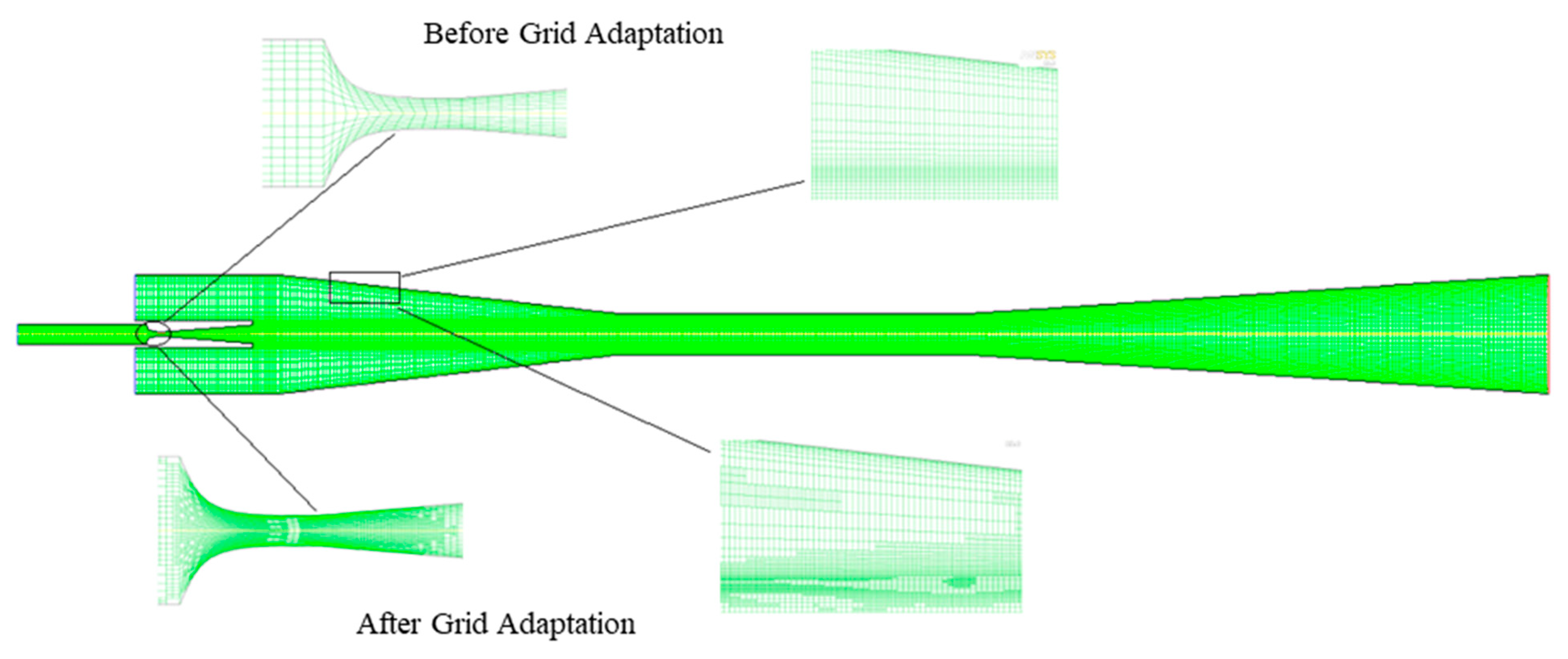
This study utilizes commercialized Computational Fluid Dynamics (CFD) modeling to numerically simulate the ejector flow. The numerical simulation involved the construction of the steam ejector refrigeration experimental system and the analysis of the ejection characteristics. Some studies have shown that the error between the simulation results of the 2D and 3D dimension models of the ejector is small [11]. In order to save calculation costs and reduce calculation time, this article uses the 2D dimension model for numerical calculations. Figure 3 illustrates the structural grid of the steam ejector, and Table 2 summarizes the numerical simulation method of this work. The structured quadrilateral mesh was adopted with a locally refined grid structure, as shown in Figure 3. In order to reduce computational costs and improve efficiency, 39,312 was chosen.
The first mesh would be carefully attended to, with the value of y+ being locally adapted to 0.61–0.93 (<1). As a result, the quality of the near-wall grid refinement was ensured, and the error of the simulations was reduced.
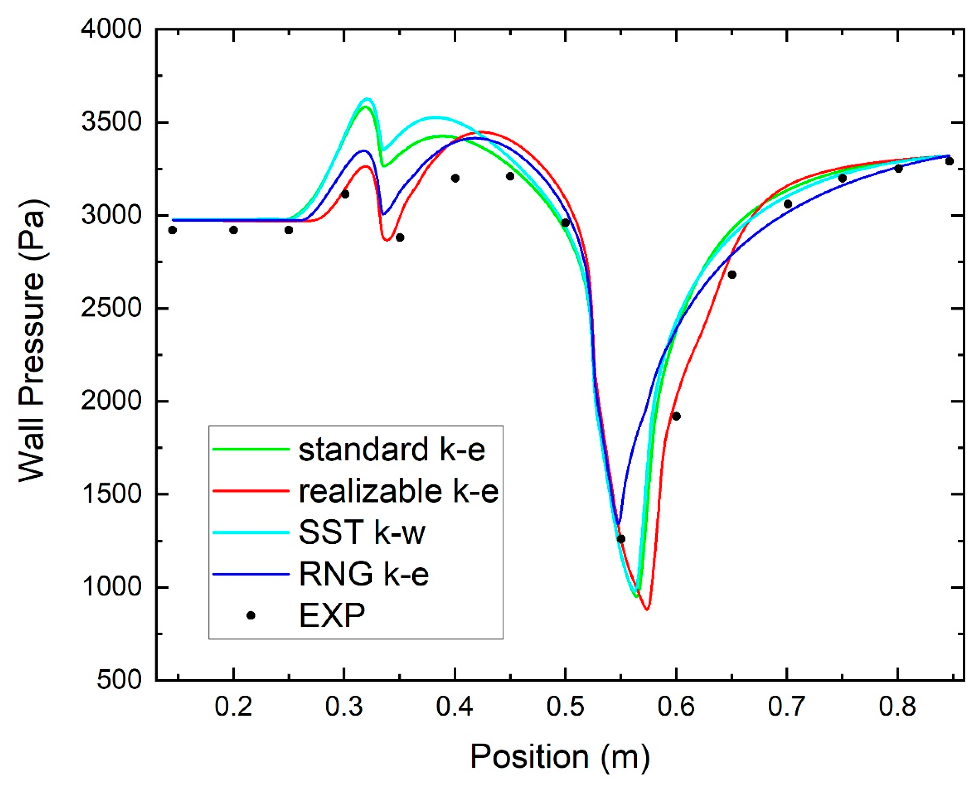
There is no turbulent flow model specifically designed to calculate the separation of the attached layer in the nozzle. Therefore, we will identify a turbulence model that provides an accurate prediction of the flow in the attached surface layer. On this basis, we experimentally compared four different turbulence models that are currently most used: the k-ε standard model, the k-ε realizable model, the k-ε RNG model, and the k-ω SST model. As the k-ε turbulent mode is a high Reynolds number method, the effect of the near-wall region must be considered. However, it was found that the Running Functional algorithm was not applicable on k-ω SST due to the small Reno number [36]. Three commonly used wall functional methods are used in jet flow field calculations, namely, the nonequilibrium wall functional method, the standard wall functional method, and the enhanced wall functional method. However, for the near-wall problem of supersonic jets, it is generally more appropriate to use the normal wall method or the strengthened wall method [3].
Figure 4 shows the distribution of the wall pressure in the steam ejector under four turbulent modes using the two near-wall surface function methods. As can be seen in Figure 4, the standard k-ε and k-ω SST turbulence models predict higher wall pressures than experimental data at x = 0.3–0.45 m, while the RNG k-ε turbulence model calculates higher wall pressure than experimental tests at x = 0.55 m. Generally, the realizable k-ε turbulence model accurately predicts the wall pressure in the whole ejector, although it calculates higher wall pressure at x = 0.45 m. This demonstrates that the developed numerical model is accurate in predicting the flow structure inside the steam ejector while considering the phase change behavior of the steam in supersonic flows.

4. Results and Discussion

4.1. Effect of Primary Fluid Pressure on Entrainment Ratios

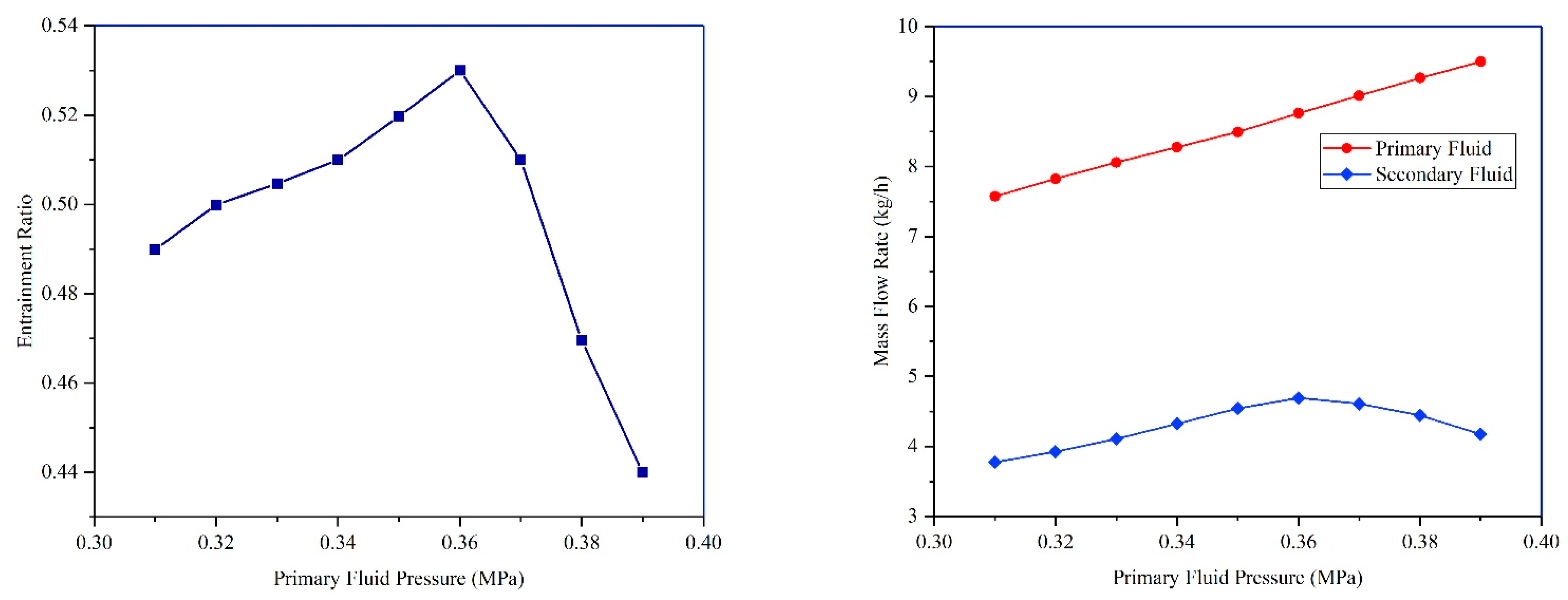
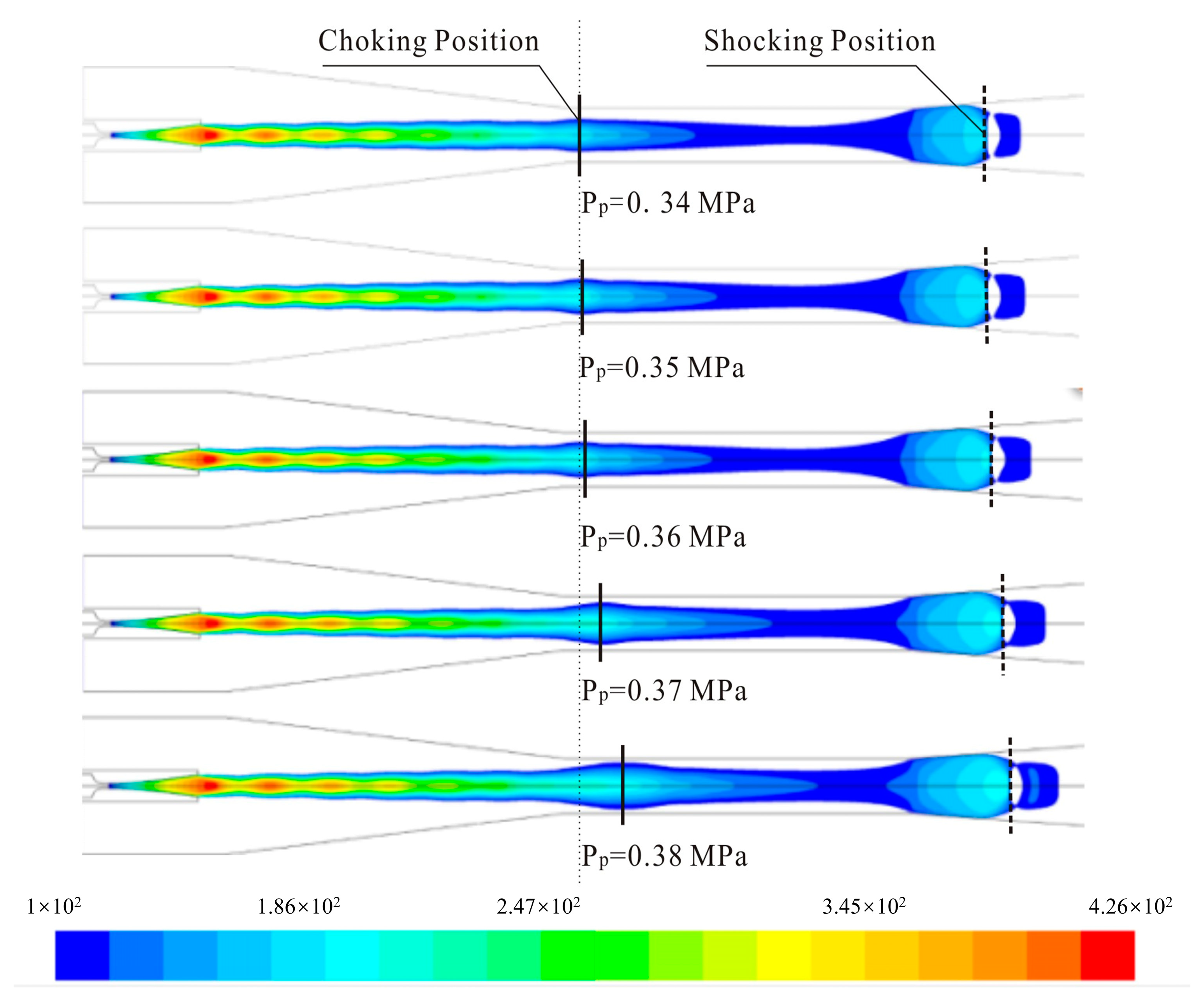
The influence of the primary fluid with varied back pressure on the entrainment ratio is shown in Figure 4 for when the pressure and back pressure of the secondary fluid were set to 3170 Pa and 4000 Pa, respectively. It was observed that the primary fluid pressure and entrainment ratio was increased proportionally. The highest entrainment ratio was obtained when the primary fluid pressure was 0.36 MPa. However, the entrainment ratio was found to decrease after 0.36 MPa. Figure 5 shows the Mach number contour graphs under varied primary fluid pressures (in order to differentiate the primary and secondary fluids, as well as the effects of the expansion core on the flow of the secondary fluid, the blank area in the contour graphs represents the flow of the secondary fluids below 1 Mach [37]), and Figure 6 presents the Mach number of the secondary fluid at 1 mm away from the wall. In Figure 5 and Figure 6, when the primary fluid pressure is below 0.36 MPa, the effective area of both primary and secondary fluids is identical at the choking position, but it the speed of the secondary fluid increases gradually. As the primary fluid pressure increases, the effective area of the second fluid first increases and then decreases, with the largest area at 0.36 MPa. Meanwhile, the flow rate of the second fluid injection is maximum. A similar circumstance was observed when the primary fluid pressure was over 0.36 MPa, and the secondary fluid remained to accelerate. The increase in the primary fluid expansion core greatly compressed the flow channel of the secondary fluid. As a result, the greatly reduced flow area led to a reduction in the mass flow rate of the secondary fluid. Conversely, the mass flow rate of the primary fluid increased with the pressure, thereby resulting in a significant reduction in the entrainment ratio. Hence, this confirmed the ejection efficiency of the ejector was the best when the primary fluid pressure was 0.36 MPa.

4.2. Effect of Secondary Fluid Pressure on Entrainment Ratios

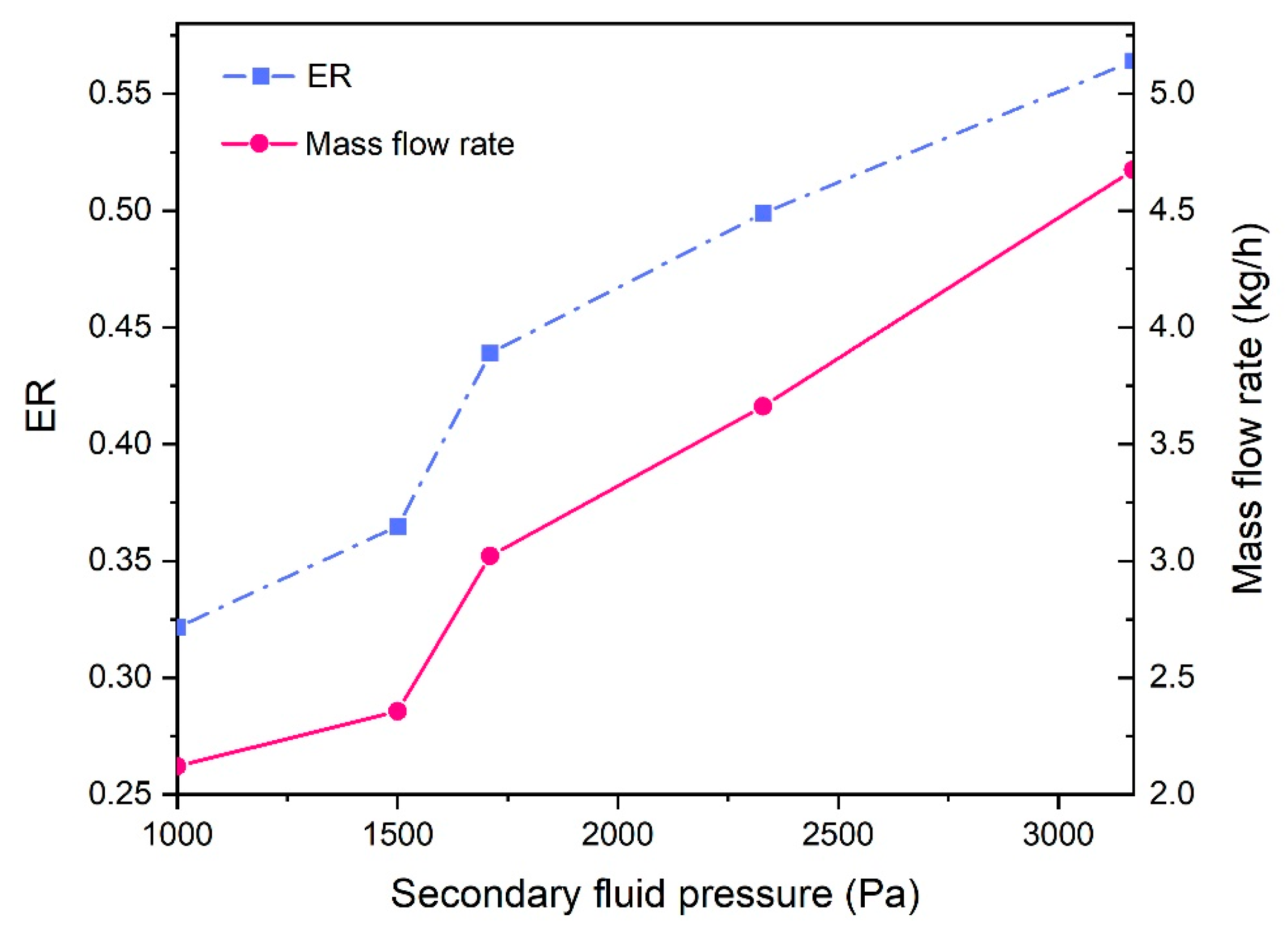
By adjusting the thermometer and relay, the temperature in the evaporator was maintained at 20 °C, and the relative saturated steam pressure was 2330 Pa. When the temperature increased to 25 °C, the saturated steam pressure was raised to 3170 Pa. The relationship between the secondary fluid pressure and the entrainment ratio and mass flow rate is presented in Figure 7 Figure 8 illustrates the Mach number contour diagram under a secondary fluid pressure of 2330 and 3170 Pa. Combined, it was found that the secondary fluid pressure increased with the mass flow rate. As the pressure and mass flow rate of the primary fluid remained constant, the increased mass flow rate of the ejector steam thereby elevated the entrainment ratio of the ejector, indicating the ejector’s efficiency was improved. Moreover, the mass flow rate of the secondary fluid increased with its pressure. This was due to the high pressure of the secondary fluid reducing the expansion angle after passing through the Laval nozzle. As a result, the ejecting flow channel of the secondary fluid was enlarged, leading to an increase in the mass flow rate of the secondary fluid at the choking position.

4.3. Effect of Back Pressure on Entrainment Ratios

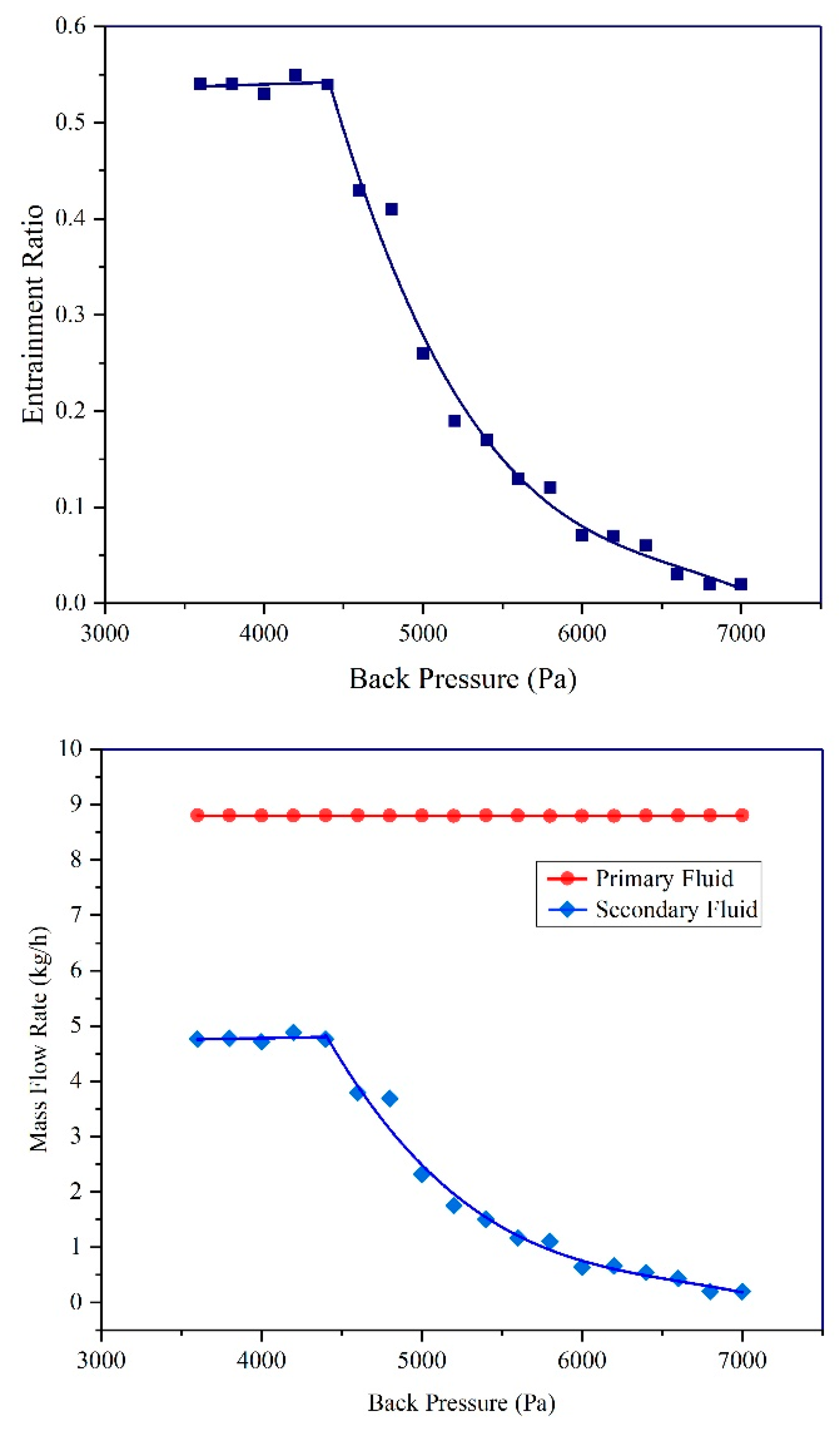
Figure 9 depicts the effects of the change in back pressure on the entrainment ratio [38] when the pressure of the primary and secondary fluid was 0.36 MPa and 3170 Pa, respectively. It can be seen that the critical back pressure was 4500 Pa. When the back pressure was lower than the critical temperature, the entrainment ratio of 0.53 was consistent. The declination in the curve was observed when the back pressure exceeded 4500 Pa. The entrainment ratio approached 0 when the back pressure was continuously rising.
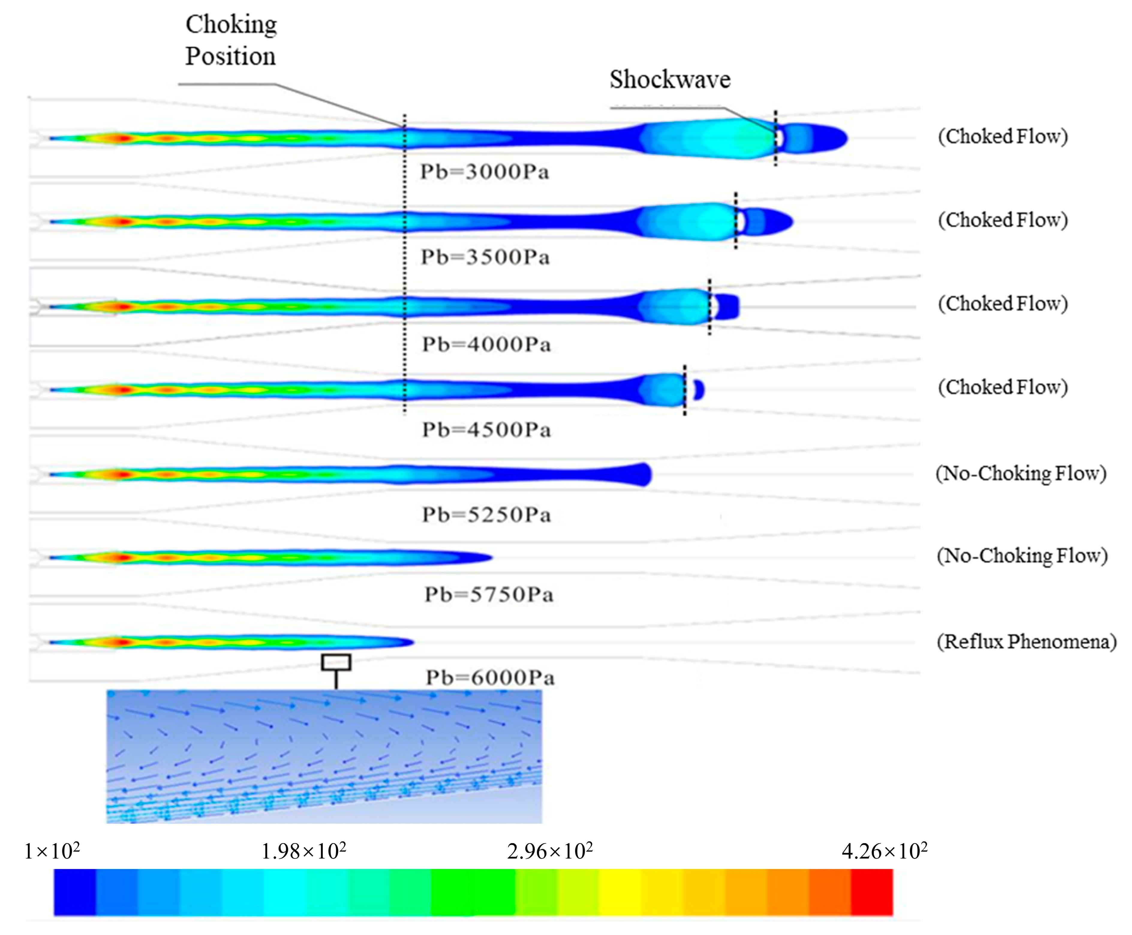
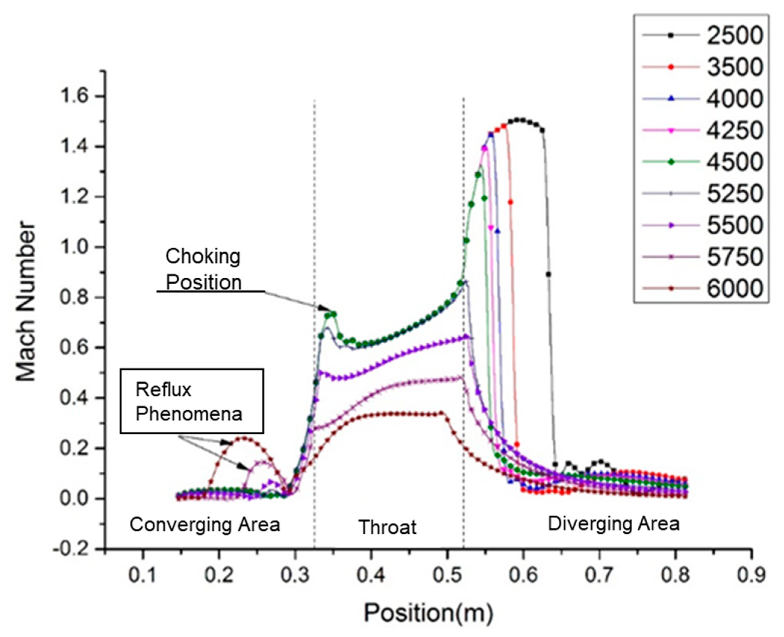
Figure 10 shows the Mach number contour graphs of the primary fluid under different back pressures. Via the simulation of the internal flow structure of the ejector, it was observed that the position of the shockwave was gradually moved upstream before the critical back pressure (Pb = 4500 Pa). Owing to the formation of the shockwave, the inviscid main flow of the supersonic fluid prevented the propagation of disturbances from downstream to upstream due to the change in back pressure [11,39]. Hence, the parameters of the effective flow area, the Mach number of secondary fluid at 1 mm away from the wall (Figure 10), and the choking position of the secondary fluid remained constant, indicating that the entrainment ratio was not interrupted. However, the formation of the shockwave no longer took place after the back pressure exceeded the critical value. The disturbance of the back pressure downstream, therefore, propagated upstream. This caused the disappearance of the secondary fluid choking, which led to the reduction in the Mach number. Concurrently, the reflux phenomenon occurred, which significantly reduced the entrainment ratio.
It can be seen in Figure 11 that when the back pressure is less than 5000 Pa, the location of the choking position is within the throat section, and the velocities are high and similar. When the back pressure is greater than 5000 Pa and less than 5500 Pa, the location of choking is at the junction of the converging area and the throat section, and the velocity is reduced and has a large velocity gradient. When the back pressure is greater than 5500 Pa, the choking position moves upward to the converging area, and the velocity is lower. At this time, there is a large fluctuation in velocity; the formation of a vortex at the wall of the ejector leads to the phenomenon of fluid reflux. If the velocity gradient increases, it will intensify the flow area of the return flow, which in turn may lead to the separation of the boundary layer of flow at the ejector wall, thus reducing the flow of fluid into the throat so that there is not sufficient kinetic energy to drive the mixing of the primary fluid with the secondary fluid. As the back pressure increases, the adequacy of fluid mixing decreases, rendering the ejector useless for operation and thus leading to ejector failure. Therefore, the main cause of ejector failure is determined by analyzing the magnitude of the back pressure and the location of the choking to reduce the likelihood of ejector failure.

5. Conclusions

This study was designed by considering the parameters of ejection efficiency and the maximum exhaust capability. The primary pump was added to maximize the ejection efficiency by providing sufficient pressure. The experiment and simulation of this study revealed the influence of the primary fluid pressure, secondary fluid pressure, and back pressure on the entrainment ratio of the ejector:
(1)
The experimental system of ejector cooling was established, and the relevant experimental data were obtained. The comparison between the experimental and simulated values showed that the relevant data of the ejector were closer to the experimental values under the non-equilibrium spontaneous condensation conditions and were more effective and realistic.
(2)
The results indicated that the excessive primary fluid pressure enlarged its expansion core, thereby reducing the effective flow area of the secondary fluid and the entrainment ratio.
(3)
As the mass flow rate and pressure of the primary fluid remained unchanged, the increased secondary fluid pressure elevated the entrainment ratio due to the reduction in the expansion angle after passing the Laval nozzle.
(4)
When the back pressure was lower than the critical back pressure of 4500 Pa, the entrainment ratio remained unchanged; however, when the back pressure exceeded its critical value, the entrainment ratio gradually reduced. The entrainment ratio approached 0 when back pressure consistently increased.
(5)
The location of the choking is a major flow characteristic that affects ejector performance and ejector failure. Mastering the flow of the choke helps us improve ejector efficiency, reduce and minimize the risk of ejector failure, and provides an important reference for optimizing the geometry and improving the efficiency of the ejector.

Author Contributions

Conceptualization, Y.X. and Y.H.; methodology, C.W. and Y.Y.; validation, C.W., Y.Y. and Y.H.; formal analysis, Y.X., Y.Y., X.W., Y.H. and C.W.; writing—original draft preparation, Y.X. and Y.H.; writing—review and editing, X.W., Y.Y. and C.W.; supervision, Y.H. and Y.Y. All authors have read and agreed to the published version of the manuscript.

Funding

This research was funded by the Chuzhou University Scientific Research Start-up Fund Projects (Funding numbers: 2016qd09 and 2023qd12).

Data Availability Statement

Data are contained within the article.

Conflicts of Interest

The authors declare no conflict of interest.

Nomenclature

ρ, ρl, ρvDensity, liquid density, and vapor density (kg/m3).
uVelocity (m/s).
u’Fluctuation velocity (m/s).
PPressure (Pa).
τijStress tensor.
ETotal energy.
αeffEffective thermal conductivity.
βMass fraction.
ΓMass generation rate (kg/s).
r ¯ Droplet average radius (m).
r*Critical droplet radius (m).
INucleation rate (1/s).
ηDroplet number density (1/m3).
qcEvaporation coefficient.
θNon-isothermal correction factor.
σDroplet surface tension (kg/m).
TThermal temperature (K).
KBoltzmann constant.
MMolecular mass (kg).
γSpecific heat capacities ratio.
hvVapor-specific enthalpy (J/kg).
RGas law constant.
SSuper saturation ratio.
CpIsobaric heat capacity (J/(kgK)).
T0Droplet temperature (K).
VdAverage droplet volume (m3).
B, CVirial coefficients (m3/kg, m6/kg2).
αvVolume fraction.
hSpecific enthalpy (J/kg).
sSpecific entropy (J/(kg.mol.K)).
kTurbulent kinetic energy.
μtEddy viscosity.
εTurbulence kinetic energy dissipation.
SijStrain rate.
C2, C1ε, C3ε, σk, σεModel coefficients.
VKinematic viscosity.
Sk, SεSource terms.

References

  1. Hamzaoui, M.; Nesreddine, H.; Aidoun, Z.; Balistrou, M. Experimental study of a low grade heat driven ejector cooling system using the working fluid R245fa. Int. J. Refrig. 2018, 86, 388–400. [Google Scholar] [CrossRef]
  2. Sharifi, N. Numerical study of non-equilibrium condensing supersonic steam flow in a jet-pump based on supersaturation theory. Int. J. Mech. Sci. 2020, 165, 105221. [Google Scholar] [CrossRef]
  3. Besagni, G.; Inzoli, F. Computational fluid-dynamics modeling of supersonic ejectors: Screening of turbulence modeling approaches. Appl. Therm. Eng. 2017, 117, 122–144. [Google Scholar] [CrossRef]
  4. Croquer, S.; Fang, Y.; Metsue, A.; Bartosiewicz, Y.; Poncet, S. Compound-choking theory for supersonic ejectors working with real gas. Energy 2021, 227, 120396. [Google Scholar] [CrossRef]
  5. Li, A.; Yuen, A.C.Y.; Chen, T.B.Y.; Wang, C.; Liu, H.; Cao, R.; Yang, W.; Yeoh, G.H.; Timchenko, V. Computational Study of Wet Steam Flow to Optimize Steam Ejector Efficiency for Potential Fire Suppression Application. Appl. Sci. 2019, 9, 1486. [Google Scholar] [CrossRef]
  6. Desevaux, P.; Mellal, A.; Alves de Sousa, Y. Visualization of Secondary Flow Choking Phenomena in a Supersonic Air Ejector. J. Vis. 2004, 7, 249–256. [Google Scholar] [CrossRef]
  7. Han, Y.; Wang, X.; Li, A.; AF, A.E.; Wen, C. Optimum Efficiency of a Steam Ejector for Fire Suppression Based on the Variable Mixing Section Diameter. Entropy 2022, 24, 1625. [Google Scholar] [CrossRef] [PubMed]
  8. Kracik, J.; Dvorak, V. Secondary flow choking in axisymmetric supersonic air ejector with adjustable motive nozzle. Appl. Therm. Eng. 2022, 204, 117936. [Google Scholar] [CrossRef]
  9. DeBonis, J.R. Full Navier-Stokes analysis of a two-dimensional mixer/ejector nozzle for noise suppression. In Proceedings of the 28th Joint Propulsion Conference and Exhibit, Nashville, TN, USA, 6–8 July 1992. [Google Scholar]
  10. Kim, H.-D.; Setoguchi, T.; Yu, S.; Raghunathan, S. Navier-Stokes computations of the supersonic ejector-diffuser system with a second throat. J. Therm. Sci. 1999, 8, 79–83. [Google Scholar] [CrossRef]
  11. Sriveerakul, T.; Aphornratana, S.; Chunnanond, K. Performance prediction of steam ejector using computational fluid dynamics: Part 2. Flow structure of a steam ejector influenced by operating pressures and geometries. Int. J. Therm. Sci. 2007, 46, 823–833. [Google Scholar] [CrossRef]
  12. Pianthong, K.; Seehanam, W.; Behnia, M.; Sriveerakul, T.; Aphornratana, S. Investigation and improvement of ejector refrigeration system using computational fluid dynamics technique. Energy Convers. Manag. 2007, 48, 2556–2564. [Google Scholar] [CrossRef]
  13. Wang, X.D.; Dong, J.L. Numerical study on the performances of steam-jet vacuum pump at different operating conditions. Vacuum 2010, 84, 1341–1346. [Google Scholar] [CrossRef]
  14. Sharifi, N.; Boroomand, M. An investigation of thermo-compressor design by analysis and experiment: Part 1. Validation of the numerical method. Energy Convers. Manag. 2013, 69, 217–227. [Google Scholar] [CrossRef]
  15. Lei, Y.; Li, S.; Lu, J.; Xu, Y.; Yong, Y.; Xing, D. Numerical Analysis of Steam Ejector Performance with Non-Equilibrium Condensation for Refrigeration Applications. Buildings 2023, 13, 1672. [Google Scholar] [CrossRef]
  16. Chen, J.; Jarall, S.; Havtun, H.; Palm, B. A review on versatile ejector applications in refrigeration systems. Renew. Sustain. Energy Rev. 2015, 49, 67–90. [Google Scholar] [CrossRef]
  17. Wang, X.; Dong, J.; Li, A.; Lei, H.; Tu, J. Numerical study of primary steam superheating effects on steam ejector flow and its pumping performance. Energy 2014, 78, 205–211. [Google Scholar] [CrossRef]
  18. Chunnanond, K.; Aphornratana, S. An experimental investigation of a steam ejector refrigerator: The analysis of the pressure profile along the ejector. Appl. Therm. Eng. 2004, 24, 311–322. [Google Scholar] [CrossRef]
  19. Rusly, E.; Aye, L.; Charters, W.W.S.; Ooi, A. CFD analysis of ejector in a combined ejector cooling system. Int. J. Refrig. 2005, 28, 1092–1101. [Google Scholar] [CrossRef]
  20. Lamberts, O.; Chatelain, P.; Bourgeois, N.; Bartosiewicz, Y. The compound-choking theory as an explanation of the entrainment limitation in supersonic ejectors. Energy 2018, 158, 524–536. [Google Scholar] [CrossRef]
  21. Besagni, G. Ejectors on the cutting edge: The past, the present and the perspective. Energy 2019, 170, 998–1003. [Google Scholar] [CrossRef]
  22. Tang, Y.; Liu, Z.; Li, Y.; Wu, H.; Zhang, X.; Yang, N. Visualization experimental study of the condensing flow regime in the transonic mixing process of desalination-oriented steam ejector. Energy Convers. Manag. 2019, 197, 111849. [Google Scholar] [CrossRef]
  23. Zhu, Y.; Cai, W.; Wen, C.; Li, Y. Numerical investigation of geometry parameters for design of high performance ejectors. Appl. Therm. Eng. 2009, 29, 898–905. [Google Scholar] [CrossRef]
  24. Rand, C.P.; Croquer, S.; Poirier, M.; Poncet, S. Optimal nozzle exit position for a single-phase ejector (Experimental, numerical and thermodynamic modelling). Int. J. Refrig. 2022, 144, 108–117. [Google Scholar] [CrossRef]
  25. Kang, S.H.; Kim, J.G.; Namkoung, H.-J. Effects of component geometries and inflow conditions on ejector operational mode. J. Mech. Sci. Technol. 2019, 33, 5003–5008. [Google Scholar] [CrossRef]
  26. Huang, B.J.; Jiang, C.B.; Hu, F.L. Ejector Performance Characteristics and Design Analysis of Jet Refrigeration System. J. Eng. Gas Turbines Power 1985, 107, 792–802. [Google Scholar] [CrossRef]
  27. Munday, J.T.; Bagster, D.F. New ejector theory applied to steam jet refrigeration. Ind. Eng. Chem. Process Des. Dev. 1977, 16, 442–449. [Google Scholar] [CrossRef]
  28. Tang, Y.; Liu, Z.; Li, Y.; Yang, N.; Wan, Y.; Chua, K.J. A double-choking theory as an explanation of the evolution laws of ejector performance with various operational and geometrical parameters. Energy Convers. Manag. 2020, 206, 112499. [Google Scholar] [CrossRef]
  29. Besagni, G.; Mereu, R.; Inzoli, F. Ejector refrigeration: A comprehensive review. Renew. Sustain. Energy Rev. 2016, 53, 373–407. [Google Scholar] [CrossRef]
  30. Han, Y.; Wang, X.; Yuen, A.C.Y.; Li, A.; Guo, L.; Yeoh, G.H.; Tu, J. Characterization of choking flow behaviors inside steam ejectors based on the ejector refrigeration system. Int. J. Refrig. 2020, 113, 296–307. [Google Scholar] [CrossRef]
  31. Fu, W.; Liu, Z.; Li, Y.; Wu, H.; Tang, Y. Numerical study for the influences of primary steam nozzle distance and mixing chamber throat diameter on steam ejector performance. Int. J. Therm. Sci. 2018, 132, 509–516. [Google Scholar] [CrossRef]
  32. Han, Y.; Wang, X.; Sun, H.; Zhang, G.; Guo, L.; Tu, J. CFD simulation on the boundary layer separation in the steam ejector and its influence on the pumping performance. Energy 2019, 167, 469–483. [Google Scholar] [CrossRef]
  33. Ishazaki, K.; Ikohagi, T.; Daiguii, H. A High-Resolution Numerical Method for Transonic Non-Equilibrium Condensation Flows through a Steam Turbine Cascade. In Proceedings of the 6th International Symposium on Computational Fluid Dynamics, Lake Tahoe, NV, USA, 4–8 September 1995; pp. 479–484. [Google Scholar]
  34. Young, J.B. An Equation of State for Steam for Turbomachinery and Other Flow Calculations. J. Eng. Gas Turbines Power 1988, 110, 1–7. [Google Scholar] [CrossRef]
  35. Young, J.B. Two-Dimensional, Nonequilibrium, Wet-Steam Calculations for Nozzles and Turbine Cascades. J. Turbomach. 1992, 114, 569–579. [Google Scholar] [CrossRef]
  36. Varga, S.; Soares, J.; Lima, R.; Oliveira, A.C. On the selection of a turbulence model for the simulation of steam ejectors using CFD. Int. J. Low-Carbon Technol. 2017, 12, 233–243. [Google Scholar] [CrossRef]
  37. Jeong, H.; Utomo, T.; Ji, M.; Lee, Y.; Lee, G.; Chung, H. CFD analysis of flow phenomena inside thermo vapor compressor influenced by operating conditions and converging duct angles. J. Mech. Sci. Technol. 2009, 23, 2366–2375. [Google Scholar] [CrossRef]
  38. Da-Wen, S. Variable geometry ejectors and their applications in ejector refrigeration systems. Energy 1995, 21, 919–929. [Google Scholar]
  39. Sriveerakul, T.; Aphornratana, S.; Chunnanond, K. Performance prediction of steam ejector using computational fluid dynamics: Part 1. Validation of the CFD results. Int. J. Therm. Sci. 2007, 46, 812–822. [Google Scholar] [CrossRef]
Figure 1. The structure and internal flow behavior of the steam ejector. (i) is sonic flow, and (iiiv) is supersonic flow.
Energies 16 07755 g001
Figure 2. Experimental system schematic diagram [32].
Energies 16 07755 g002
Figure 3. The structural grid of the steam ejector.
Energies 16 07755 g003
Figure 4. Static pressure comparison under different turbulence models.
Energies 16 07755 g004
Figure 5. The relationship between primary fluid pressure and entrainment ratio.
Energies 16 07755 g005
Figure 6. Mach number contours in ejectors.
Energies 16 07755 g006
Figure 7. The relationship between secondary fluid pressure and entrainment ratio.
Energies 16 07755 g007
Figure 8. Mach number contours of the secondary fluid pressure under 2330 and 3170 Pa.
Energies 16 07755 g008
Figure 9. The relationship between back pressure and entrainment ratio.
Energies 16 07755 g009
Figure 10. Mach number contour graphs under different back pressures.
Energies 16 07755 g010
Figure 11. Mach number of back pressure at 1 mm away from the wall.
Energies 16 07755 g011
Table 1. The dimensions of the components.
ComponentAspectSize (mm)
Nozzle ThroatDiameter2.5
Nozzle OutletDiameter11
Nozzle Throat to OutletLength48
Diffuser ThroatDiameter24
Diffuser ThroatLength192
Diffuser InletDiameter70
Diffuser OutletDiameter70
Diffuser Inlet ReducerLength188
Diffuser OutletLength322
Ejector Suction PortDiameter54
Table 2. Numerical simulation method.
Discrete FormatThe control equations are discretized into algebraic equation systems that can be numerically solved using the finite volume method. The coupled implicit solver is employed to solve these equations. The diffusion was discretized using the central difference scheme in the Coupled Implicit Model. The second-order upwind scheme was used to discretely solve the convective terms.
MeshingThe mesh element in certain areas of the nozzle wall was refined to cope with the Enhanced Wall Treatment near-wall modeling method. The initial generated mesh number was 53,463. After the mesh fining with the aid of an adaptive technique, the final mesh number was 62,796.
Disclaimer/Publisher’s Note: The statements, opinions and data contained in all publications are solely those of the individual author(s) and contributor(s) and not of MDPI and/or the editor(s). MDPI and/or the editor(s) disclaim responsibility for any injury to people or property resulting from any ideas, methods, instructions or products referred to in the content.