Article

Analytical Approach for Estimating the Average Torque of Synchronous Motors by Using the Flux Density in the Air Gap †

1
Department of Electrical Engineering, National Taipei University of Technology, Taipei 10608, Taiwan
2
Department of Electrical Engineering, National Central University, Tauyuan 32001, Taiwan
*
Author to whom correspondence should be addressed.
This paper is an extended version of our paper published in 2022 International Power Electronics Conference, Himeji, Japan, 15–19 May 2022; pp. 2721–2727.
Energies 2023, 16(23), 7832; https://doi.org/10.3390/en16237832
Submission received: 29 October 2023 / Revised: 14 November 2023 / Accepted: 27 November 2023 / Published: 28 November 2023

Abstract

:
In this study, a generalized torque estimation method is proposed for synchronous motors, including surface permanent magnet synchronous motors (SPMSMs), synchronous reluctance motors (SynRMs), and interior permanent magnet synchronous motors (IPMSMs) for building the analytical motor model. The average motor torque is estimated using the Lorentz force by the generated flux density in the air gap to determine the relationships among torque, flux density, and injected current. In the proposed method, the generated flux density is derived step by step by considering the effects of magnetic flux saturation, the stator slot, the rotor barrier, and permanent magnets (PMs) to ensure that the generated average torque complies with the operating condition of the motor. To verify the proposed method, the output torque of finite element analysis (FEA), Maxwell 2D, is compared to the proposed method in a SPMSM. Moreover, a phasor diagram is plotted to determine the mechanism through which torque is generated in SynRMs and IPMSMs. A SynRM and an IPMSM with ferrites PMs are analyzed using the proposed method, FEA, and the experimental results of this study indicate the effectiveness.

1. Introduction

Because of their high power density and high efficiency, synchronous motors are widely used in industrial applications of electric powertrain systems. SynRMs without conductors or magnets are more efficient than induction motors and are cheaper than permanent magnet synchronous motors (PMSMs). Moreover, the structure of SynRMs is simple, and their output torque is insensitive to the operation temperature. However, SynRMs do have a nonlinearity of output torque and a slow dynamic response; a low power factor leading to an increase in the cost of the semiconductor inverter; and a lower power density and constant power speed range (CPSR) compared to PMSMs, which means that the SynRM is not suitable for application of high power density. Based on this, the addition of magnets mitigates the disadvantages of SynRMs. Because of the high expense of rare-earth permanent magnets (PMs) such as neodymium–iron–boron PMs with dysprosium, PM-assisted SynRMs (PMASynRMs), which have a similar structure to SynRMs, have been developed using low-cost magnets made from non-rare-earth materials to maximize the motor performance including output torque and power factor [1,2,3]. Because the high magnetic saturation of motors under heavy loads results in the generation of nonlinear torque, FEA software is usually used to design such motors [4,5,6]. Researchers have employed these software programs to increase output torque, power density [4], and rotor eccentricity [5], to conduct rotor structure analysis, and to evaluate the relationship between rotor structure and stator winding for accelerating the development of synchronous motors [6]. Several studies [7,8,9,10] have discussed the effect of magnetic saturation on the output torque and rotor barrier to determine the optimal control strategy for synchronous motors.
The generating torque of synchronous motors is strongly affected by magnetic saturation. Therefore, torque estimation methods based on ideal dq axis currents in the synchronous frame make it difficult to obtain accurate results. In [11,12], flux density was used to calculate output torque. The magnetomotive force (MMF) between the stator and the rotor has been used to explain the mechanism through which torque is generated in synchronous motors [13,14,15]. The torque and maximum torque per ampere (MTPA) can be estimated using a fitting model [16]. In general, motor torque is generated by a magnetic field in the air gap, wherein the fundamental and harmonics components contribute to the average torque and torque ripple, respectively [17,18,19]. The researchers of [20,21] indicated the relation between Lorentz’s force and generating torque without explaining the saturation effect. The studies [22,23] focus on the cogging torque calculation by modeling the slot geometry in a reluctance circuit under low saturation conditions. The authors of [24,25] investigated motor torque by considering the MMF and Maxwell stress tensor [26,27,28,29,30,31], wherein [31] mentioned the B-H curve of silicon steel under different operating loads. A saturation coefficient has been proposed for modifying the torque model of synchronous motors by considering the core reluctance.
In this study, a method is proposed for estimating the average torque in accordance with the flux density in the air gap, and the torque is derived at a certain point in time, which can be regarded as time-independent. The coordinate system of flux density in the air gap was proposed for different types of synchronous motors with magnitude and angle information. Moreover, generating flux density was mentioned by considering stator, rotor, and PMs step by step. Thus, the torque generation mechanism identified using this method is more intuitive than the aforementioned methods. The flux density in the air gap depends on the stator–rotor interaction. The rotor effect is modeled through FEA because of the complex geometry of the flux barrier. The SPMSM is modeled to verify the analytical method in simple geometry, and the maximum error of the output torque between the proposed method and FEA simulation under different leading current angles is less than 4.9%. Furthermore, the performance of the designed PMASynRM, a SynRM with the same geometry, is used as a benchmark in FEA, wherein some coefficients of the IPMSM-type motor are calculated using the assistance of FEA due to the complicated motor geometry. The relation of the phasor diagram between average torque and flux density in an air gap could be observed from the proposed method, FEA, and experimental results, and the analytical concept could be applied to motor design in the initial stage.
The rest of this study is organized as follows. Section 2 provides a description of the torque generated using a synchronous motor and the definition of flux density in the air gap under different combinations between stator and rotor. Moreover, a phasor diagram based on fundamental flux density is used to explain the torque generation mechanism of a synchronous motor. Section 3 describes an analytical approach for determining the flux density in the air gap caused by the stator–rotor interaction, such as the effects of magnetic flux saturation, the stator slot, and non-rare earth (ferrite) PMs. Section 4 describes the verification of the proposed approach through FEA, and the electromagnetic phenomenon exhibited by the proposed motor is discussed. Section 5 details the testing of the designed PMASynRM. Under a rated current and speed, the torque of the PMASynRM obtained using the proposed method and experimentation differ by 7.1%, indicating the proposed method’s effectiveness.

2. Torque Generated Using a Synchronous Motor

The simplified schematic of an elementary three-phase, two-pole synchronous motor is shown in Figure 1. The stator’s MMF (denoted as fs) is generated by a three-phase composite current I3p. In Figure 1, θi and θm denote the lead current and mechanical angles, respectively.
The Lorentz force law is used to calculate the output torque [32] in the air gap (Figure 2). The force generated by a synchronous motor (dF) can be expressed as follows:
d F = i d l s t k × B
where i, B, and lstk represent the stator current, flux density in the air gap, and stack length of the motor, respectively.
The generated torque Te and average torque T1 of a synchronous motor (Figure 2) can be derived as follows [33]:
T e = r g l s t k 2 π × P 2 B g d f s
T 1 = P 2 μ 0 g r g l s t k π f s , 1 f r , 1 sin θ i
where P, μ0, rg, and g are the pole number, the vacuum permeability, the radius of the air gap, and the length of the air gap, respectively. Bg denotes the product of the flux density in the air gap with the magnetic reluctance produced by the stator, the rotor barrier, and the PM. The stator’s MMF (fs) is only generated by a three-phase current without considering the rotor effect. The rotor’s MMF (fr) is defined as the instantaneous spatial distribution induced by the given three-phase stator current with flux barriers inside the rotor. The terms fs,1 and fr,1 represent the fundamental MMFs produced by the stator.
In this study, a method is proposed for estimating the average torque generated by synchronous motors from the flux density in the air gap [34]. The flux density produced in the air gap in different cases (Figure 3) is described as follows:
  • In Figure 3a, the flux density generated in the air gap by the current (denoted Bs) is only affected by fs and not the rotor effect of the flux barrier or the PM;
  • The flux density generated in the air gap by the PM (BPM) is unaffected by the stator slot and stator winding, as displayed in Figure 3b;
  • The flux density generated in the air gap by the rotor (Br) is defined as the composite flux density of a SynRM, as illustrated in Figure 3c;
  • The term Bg denotes the sum of BPM and Br and represents the composite flux density of an IPMSM (Figure 3d);
  • The θm is defined as the angle referred to as the Xa axis in the stationary frame, and the θm from 0° to 360° represents one revolution of the air gap in the motor.
The general equation of the average torque T1 generated by a synchronous motor under fundamental fluxes is as follows:
T 1 = 1 k s P 2 g μ 0 r g l s t k π B g , 1 B s , 1 sin θ g s , 1
where Bg,1 and Bs,1 are the peak fundamental components of Bg and Bs, respectively. The term θgs,1 denotes the angle between Bg,1 and Bs,1. The flux Bs is generated by the three-phase stator currents at t = 0, and these currents are defined as follows:
I u = I p × sin θ i
I v = I p × sin 2 π 3 + θ i
I w = I p × sin 2 π 3 + θ i
I 3 p = 3 2 I p
where Ip and I3p are the peak values of the single-phase and three-phase current, respectively. A schematic of the lead current angle, the magnetic flux, and the flux density generated by the stator current is displayed in Figure 4. When the lead current angle increases, the Bs waveform moves farther away from the Xa-axis, defined as the motor’s mechanical starting point, equivalent to a lag effect at the air gap coordinates. Moreover, the sum of the current lead angle θi and the flux density angle of the stator θs is 90°.
The form factor ks generated by the stator current is defined to quantify the magnetic flux saturation ksat and stator slot kslot effects as follows:
k s = B s , 1 B s l , 1 = k s a t × k s l o t
where Bsl,1 is the linear flux density caused by the ideal stator when not considering the effect of magnetic saturation or the stator slot on the motor.
The phasor diagram of the fundamental flux density for one period (Figure 5) is adopted to explain the basic torque-generation mechanism of synchronous motors, including SynRMs and IPMSMs. The flux density Bg,1 can be expressed as follows:
B g , 1 = B r , 1 + B P M , 1
Under the given Bs,1 and θs,1 values, the following phenomena can be noted in Figure 5:
  • The Bs of the SPMSM is the smallest due to the increasing equivalent air gap by removing the PMs. Moreover, Br,1 = Bs,1 and Bg,1 = Bs,1 + BPM,1 for the solid rotor structure without a flux barrier. Furthermore, the torque and sin (θgs,1) is zero when θi increases to 90°;
  • The parameter θgs,1 increases in the presence of a PM. Therefore, the average torque generated by an IPMSM is higher than that generated by a SynRM. Wherein, Bg,1 = Br,1 for a SynRM without the PM effect.

3. Analytical Approach for Torque Estimation

In this section, the generating torque is described from flux density in the air gap. The SPMSM could be assumed as the simple case in the synchronous motors; the analytical approach of a SPMSM is modeled and compared to FEA results to show the effectiveness of the proposed method. Then, the SynRM and the PMASynRM are formulated with FEA-assisted to indicate the saturation and the PM effects. The key specifications and geometries of the designed motors are presented in Table 1. The three motors have 4 poles and 36 slots (4P36S) with the same stator and rotor sizes. Moreover, their stator winding configurations are the same. In the spatial coordinates, the waveform of the flux density is two periods because of the four poles and integer slots per pole.

3.1. Flux Density in the Air Gap for an Ideal SPMSM

The relation between the geometry and flux density in the air gap mentioned in Figure 3 could be simplified to Figure 6. Moreover, the Bs is equal to the Br due to the ideal rotor structure without a flux barrier, and the PM is uniformly distributed along the rotor surface.
In [33], the effect of the stator on the flux distribution was determined using a winding function, and the three-phase stator current was determined to be the input source for the flux density in the air gap. In this study, Bsl is calculated using the linear permeability of silicon steel, and the rotor is set as a solid without flux barriers or magnets. The waveform of the winding function at t = 0 is displayed in Figure 7.
The flux density generated in the air gap by the three-phase current is expressed as follows when considering the linear permeability of silicon steel:
B s l = N μ 0 2 g n u θ m I u + n v θ m I v + n w θ m I w
where N is the number of the winding turns. Moreover, nu(θm), nv(θm), and nw(θm) are the winding functions of the phases defined in Figure 7.
In the case of an ideal SPMSM, the minimal winding area and non-slot structure are built to minimize the saturation effect. Moreover, the PM will be removed when the flux density is generated in the air gap by the three-phase current. The equivalent air gap could be regarded as a summation of the length of the air gap and the PM’s thickness. It ensures the linear permeability of silicon steel for the ideal SPMSM; hence, the ks in Equation (9) is assumed to be a unity for the ideal SPMSM. The Bs waveforms of the proposed method and the FEA-simulated result are illustrated in Figure 8.
For the definition of a flux path generated by PMs for an ideal SPMSM, the calculated and simulated results are shown in Figure 9; the absolute peak value of BPM is expressed as follows:
B P M = A m A g × B P M R 1 + μ r g l m A m A g
where BPMR is 1.16 T, which is defined as the flux density of a PM’s remanence from the datasheet. The cross-section of PMs (Am) and the related air gap (Ag) are the same. Moreover, the permeability of PMs is similar to air; hence, Equation (12) could be rearranged as below.
B P M = B P M R 1 + g l m = B P M R 1 + 0.3 2 0.87 B P M R
In the ideal SPMSM, the Bg could be regarded as a summation of Bs and BPM. The calculated and FEA results of Bg under different lead current angles are shown in Figure 10. The aforementioned results indicate the closed waveforms of flux density in the air gap between FEA and the proposed method. The SPMSM torque results under different conditions are listed in Table 2, calculated using Equation (4) with the fundamental components of flux densities from a FFT analysis and motor geometry. The maximum error between the FEA simulation and the proposed method is less than 4.9%, which indicates the effectiveness of the proposed method without considering saturation.

3.2. Flux Density in the Air Gap for PMSMs with a Rotor Barrier

Because the complicated rotor structure and saturation problem occur in the IPMSMs with flux barriers in the rotor, some coefficients are calculated using FEA-assisted. Figure 11 displays the flowchart of the proposed method for estimating the average torque of a synchronous motor. First, the three-phase current (iu, iv, and iw) is used as the input source to analyze the stator winding distribution and calculate the linear flux density at the air gap (Bsl). Subsequently, the geometries of the stator and rotor, which are made of silicon steel, the effect of the stator slot, and the nonlinear behavior of silicon steel are used to determine Bs under different currents. Moreover, Br is generated when Bs flows through the rotor, and Br can be calculated using the proposed method from the rotor reluctance for a simple rotor structure (such as a SPMSM or an IPMSM with a single-layer rotor barrier). However, the motors designed in this study have a complex reluctance distribution because of their three-layer rotor barrier; thus, FEA is used to analyze the form factor of the rotor to obtain a more accurate Br value. Subsequently, BPM is derived, and Bg is calculated by summing Br and BPM. Finally, the flux density in the air gap is analyzed by determining the fundamental component to calculate the average output torque of the motor.

3.2.1. Flux Density Generated by the Current in the Air Aap (Bs)

Using Equation (11), Bsl is calculated under a rated phase current of 9.4 Arms and θi values of 0° and 30° (Figure 12). Moreover, the magnitude of the fundamental component Bsl,1 is 3.9 T, and this magnitude is unaffected by the lead current angle. In addition, the maximum flux density of general silicon steel is less than 2 T. Therefore, the calculations in this section are performed by considering the influences of magnetic saturation and the stator slot.
Because of the requirements of the winding space, the width of the flux path is reduced by the stator slot. A complete magnetic circuit in a 1/4 motor model is displayed in Figure 13a. In this circuit, the saturation phenomenon becomes more serious at a greater stator current. In order to consider the effect of magnetic flux saturation on the flux density in the air gap (Bs,sat), the magnetic circuit displayed in Figure 13b is constructed. When the saturation of the silicon steel increases, the reluctance of the silicon steel also increases, which results in a decrease in Bs,sat.
B s , s a t = k s a t × B s l
k s a t = 2 R g 2 R g + R s t e e l
R g = g π 4 μ 0 r g l s t k k t o o t h
R s t e e l = l s , s a t μ s t e e l l s t k w s , s a t
where ktooth is the ratio of the tooth width to the slot width in a symmetric magnetic circuit (approximately 0.6 for the proposed motors). Moreover, ls,sat and ws,sat are the equivalent saturation length and width on the flux path (160 and 25 mm, respectively), wherein the relative permeability of silicon steel (μsteel) is affected by the interactions between saturation and the air gap effect are considered using FEA-assisted. The relation between the excited current and μsteel is expressed as follows:
μ s t e e l = B s t e e l H s t e e l = B s t e e l l s , s a t N I 3 p H s l g
where N is 25. Moreover, Bsteel and Hs are defined as the flux density of silicon steel and the magnetic field strength in the air gap under current excitation.
The saturation coefficient ksat is affected by the current magnitude indicated in Equations (15)–(18). This coefficient can be regarded as a magnitude scaling factor. The relationship between ksat and the three-phase current I3p is shown in Figure 14. The term ksat is equal to approximately 0.39 under a rated current of 20 Apeak (Ip = 9.4 Arms).
In addition, because the flux density in the air gap is affected by the slot structure, which results in variation in the equivalent length of the air gap, the authors of [35,36,37] modified the air gap’s length using Carter’s coefficient. In the present study, the stator structure is modified using a simple model, which is displayed in Figure 15. The model displayed in this figure is a half-slot model with θ0 as the symmetrical axis. The flux paths in the air gap in this model are defined as follows:
  • Path 1 is from the stator yoke side to the rotor;
  • Path 2 is from the tooth-side edge to the rotor;
  • Path 3 is the shortest path from the tooth to the rotor and does not vary with g.
Path 1 has the highest reluctance among the three paths; thus, the size of the air gap is considerably reduced.
The permeability of a closed path can be obtained using Ampere’s law. The permeability of Paths 1 and 2 can be expressed as follows:
P 1 = μ 0 l s t k 0 w s l o t 2 r α [ g + d t o o t h ] 1 d x
P 2 = μ 0 l s t k 0 r α [ π r 1 2 + g   ] 1 d r 1
Because the flux flows through the path with the lowest reluctance, the boundary of Path 1 cannot exceed that of Path 2, and rα can be expressed as follows:
r α = min ( W s l o t 2 , d s i R )
The equivalent length of the air gap at the slot and Carter’s coefficient (cs) can be expressed as follows:
g e q u = μ 0 l s t k W s l o t 2 ( P 1 + P 2 )
c s ( θ m ) = g e q u g = μ 0 l s t k W s l o t 2 g ( P 1 + P 2 )
The calculated value of cs for the proposed motors is 5.33. The flux density in the air gap can be expressed as follows when considering the saturation and slot effects:
B s = k s a t k s l o t B s l
k s l o t = 1 c s ( θ m ) ,   θ 0 θ m < θ 1 1 ,   θ 1 θ m < θ 2
According to Equation (25), an increase in the equivalent length of the air gap at the stator slot causes a considerable reduction in the flux density Bs. Figure 12 shows the Bsl waveform calculated under the linear condition. Moreover, according to Figure 14, ksat is approximately 0.39 at the rated current (I3p = 20 Apeak). The waveform obtained for Bs when considering the slot effect is displayed in Figure 16. The maximum value of the fundamental component Bs,1 is approximately 1.16 T. Finally, the value of ks is determined to be 0.3 by substituting the values of Bsl,1 (3.9 T) and Bs,1 into Equation (9), where the equivalent attenuation of the slot (kslot) is approximately 0.77.

3.2.2. Flux Density Generated in the Air Gap by a Rotor Barrier (Br)

When the flux provided by the stator winding flows through the rotor, the rotor exhibits different flux densities Br in the air gap depending on the relative position of the flux path from the rotor barrier, as displayed in Figure 17. In this study, the relationship between Bs,1 and Br,1 is obtained by fixing the rotor position and adjusting the magnitude and phase of the three-phase current, which is the same as the operating condition at t = 0. The equivalent magnetic circuit can be directly calculated if the rotor structure is simple. However, the proposed motors have a complex three-layer rotor barrier; thus, the fitting relationships of θi with Br,1 and θr,1 are determined under the rated current through FEA. The relationship between Bs,1 and Br,1 can be expressed as follows:
k r , 1 ( θ i ) = B r , 1 B s , 1
θ k r , 1 ( θ i ) = tan 1 B r , 1 B s , 1
where kr,1(θi) and θkr,1(θi) are the magnitude and phase, respectively, of the ratio of Br,1 to Bs,1 in polar coordinates.
Figure 18 shows the fitting results for kr(θi) and θkr,1(θi) under the rated current. These results are used with Bs,1 to obtain Br,1 and θr,1 (0.95 and 79.6°, respectively). When the lead current angle increases, the direction of the composite flux changes to the Ya-axis with the characteristic of high rotor reluctance, which causes a reduction in the flux density in the air gap.

3.2.3. Air Gap Flux Density Generated by the PM (BPM)

The equivalent magnetic circuit of an i-layer rotor is illustrated in Figure 19. This circuit is based on the assumption that the stator structure is ideal and that the short circuit is made of silicon steel [38]. The output torque characteristics of a PMASynRM can be obtained after inserting a PM into a SynRM with the same rotor and stator geometries. Therefore, this section explains the effect of inserting a ferrite PM into a no-load SynRM. The equivalent magnetic circuit of the rotor structure of the proposed motors is displayed in Figure 19a. The flux in this circuit is mainly provided by the stator current in the proposed motors because of the low remanence of the ferrite PM; thus, the short-circuit flux caused by the ribs (Rribl,li and Rribr,li) can be neglected. Moreover, the barriers Rbl,li and Rbr,li can be regarded as a parallel connection in Rbarrier,li due to the symmetric geometry of the flux barriers. The simplified equivalent reluctance circuit and rotor geometry are displayed in Figure 19b, where ϕrem,li, RPM,li, Rbarrier,li, and Rgap,li are the remanence flux of the PM, the reluctance of the PM, the reluctance of the barrier, and the reluctance of the air gap in the i-layer, respectively.
The equivalent circuit of the PMASynRM proposed in this paper is illustrated in Figure 20, and its parameters for different layers are defined in Table 3. For this circuit, the general equations of the remanence flux and reluctance in the ith layer can be expressed as follows:
ϕ r e m , l i = B r e m , l i w P M , l i l s t k
R b a r r i e r , l i = l b , l i 2 μ 0 w b , l i l s t k
R P M , l i = l P M , l i μ 0 w P M , l i l s t k
R g a p , l i = g μ 0 r g ( θ b s , l i θ b e , l i 1 ) l s t k
According to Gauss’s law, the flux density in the air gap (BPM,li) can be obtained from the reluctance in the air gap (Rgap,li) and the ϕgap,li value in the ith layer as follows:
B P M , l i = ϕ g a p , l i r g ( θ b s , l i θ b e , l i 1 ) l s t k , θ b e , l i 1 θ m < θ b s , l i
where ϕgap,li can be calculated from Figure 20.
Figure 21 displays the waveform of BPM, which is calculated using Equation (32). The error between the fundamental component obtained using the proposed method and that obtained through FEA is only 2.3%, which indicates the effectiveness of the proposed method for calculating BPM.
According to Equation (10), when the proposed PMASynRM is dominated by electric load, the magnetic field Bg,1 can be regarded as the vector synthesis of Br,1 and BPM,1. The phasor diagram of the rotor of the proposed PMASynRM is shown in Figure 22. FEA simulation and the proposed method are used to analyze the composite flux Bg,1, and the relevant results obtained under lead current angles of 30° and 60° and the rated current are presented in Table 4. These results indicate the effectiveness of the proposed method for calculating the composite flux density. In addition, because the magnetic field created by the ferrite PM is weak in the proposed design, silicon steel does not exhibit magnetic flux saturation when only the PM is considered. Therefore, determining BPM,1 without considering the stator slot effect is reasonable.

3.2.4. Analysis of the Average Torque

To verify the effectiveness of the proposed torque formula, the flux densities in the air gap obtained through FEA and the proposed method are substituted into Equation (4) for comparison (Table 5); the torque error is discovered to be less than 1.8%.
Studies [39,40,41,42,43] have indicated that a PM can increase the output torque, the output power, and the power factor of a SynRM. According to Equation (4) and Figure 5, the PM increases the output torque of the proposed SynRM by increasing θgs,1. Figure 23 shows the output torque curves of the designed SynRM and PMASynRM under the rated current. The maximum output torque of the proposed SynRM (28.4 Nm) occurs at a θi value of 60° because of magnetic flux saturation. The maximum output torque of the PMASynRM can be increased to 31.8 Nm.

4. FEA of the Flux Density

The results of FEA are used to examine the influences of the stator and rotor—including the flux saturation phenomenon, the slot effect, and the rotor flux barrier—on the flux density in the air gap under different currents.

4.1. Flux Saturation Effect

When silicon steel is a nonlinear material, an increase in the current increases the flux saturation of the motor. To separate the influence of the current magnitude on the saturation of the silicon steel, the stator and the rotor with the material of silicon steel are set as solid structures without a slot or a flux barrier. The flux density distributions under different stator currents are displayed in Figure 24, and the motor flux saturation at the rated phase current is considerably higher than that under light load.
Equations (14)–(18) indicate that flux saturation causes a considerable increase in the reluctance of silicon steel, which results in a decrease in the flux density in the air gap. Figure 25 shows the flux densities in the air gap under different currents for linear and nonlinear silicon steel. The linear flux density produced by the stator current Bsl is calculated using Equation (11) and compared with the nonlinear flux density Bs obtained through FEA. Silicon steel can be considered to exhibit linear behavior under a light load. The difference between the results obtained using Equation (11) and FEA indicates that considering the flux saturation and modifying the magnitude of the flux density in the air gap under a heavy load are essential tasks.

4.2. Slot Effect

The flux density distribution obtained when considering the stator slot effect is displayed in Figure 26. The flux saturation at the yoke and tooth is higher when considering this effect than when not considering this effect (Figure 24b).
As the equivalent air gap length at the slot is increased, the flux density in the air gap decreases considerably. Figure 27 shows the waveform of Bs obtained through FEA simulation and the proposed method. The maximum error in the fundamental component magnitude is 0.9%.

4.3. Flux Barrier Effect

When the flux generated by the stator winding flows through the rotor, its magnitude is affected by the reluctance of the flux barriers. As displayed in Figure 28, the current angle varies with the position of the fixed rotor. The minimum rotor reluctance is achieved when θi is 0°; in this case, Br is similar to Bs. The reluctance increases with θi, which causes a decrease in the magnitude and phase of Br. The waveform of Br obtained through FEA under the rated current and different θi values is displayed in Figure 29. The magnitude and phase of the fundamental component Br,1 are presented in Table 6.

4.4. Effect of the PM

The inserted PMs cause a fixed phase and magnitude on the negative Xa-axis, which results in θgs,1 being greater than θr,1; thus, the output torque is greater. The waveforms of Bg and Br obtained through FEA under the rated current, and a θi value of 60° are displayed in Figure 30. To quantify the effect of the PM on the output torque, sin (θgs,1) and sin (θrs,1) are compared (Figure 31). The parameter sin (θgs,1) is increased by inserting the PM into the designed SynRM.

4.5. Output Torque

The output torque obtained through FEA under the rated current is displayed in Figure 32. The speed of the proposed PMASynRM is set as 1200 rpm, and its average torque (TAvg) is set as 23.2 and 31.3 Nm when θi = 30° and 60°, respectively. Figure 33 depicts the TAvg values obtained through FEA simulation and the proposed method for the proposed SynRM and PMASynRM under different operation conditions; the maximum error is less than 2.6%.

5. Experimental Results

The parts and testing setup of the designed PMASynRM are depicted in Figure 34 and Figure 35, respectively. The torque sensor manufactured by Kistler was used to measure the average torque, and the incremental encoder in the PMASynRM had a pulses per revolution value of 2500; the adopted control methodology with a sinusoidal pulse width modulation (SPWM). A digital signal processor (DSP-TMS320F28075, Texas Instruments, Dallas, TX, USA)-based test platform was constructed to verify the effectiveness of the FEA simulation and proposed calculation method.
Figure 36 displays the output torques of the proposed PMASynRM under different loads and angles at rotation speeds of 300 and 1200 rpm. This figure depicts curves for the MTPA under various current magnitudes. The magnetic saturation of the motor increased as the current increased. Moreover, the θi value corresponding to the maximum torque increased from 45° to 55° when the phase current was increased from 50% of the rated load (4.7Arms) to the rated load (9.4 Arms). This phenomenon suggests that the effect of magnetic saturation must be considered when torque control is used. Similar MTPA results were obtained through FEA and the proposed method. In addition, the MTPA current must be the same within the voltage limitation of the inverter. The differences in the experimental results under different motor speeds might have been caused by material characteristics, core loss, and mechanical effects. Nevertheless, under the aforementioned conditions, the maximum error between the results obtained through FEA simulation, the proposed calculation method, and experimentation was less than 10% under a rated current, wherein the quantitative comparison of the torque results is shown in Table 7. Moreover, the motor efficiency of the FEA-simulated and experimental results under a rated current with 60° of θi is 91.1% and 90.7%, respectively. The core loss caused by the saturation phenomenon of the motor mentioned in Section 4 would decrease the motor efficiency.

6. Conclusions

In this study, a method is proposed for estimating the average torque of synchronous motors. The proposed method is verified for a SPMSM without serious saturation according to a 4.9% maximum error compared to FEA results. Moreover, because SynRMs and PMASynRMs have an inescapable saturation effect, FEA-assisted is used for fitting coefficients, including the effects of stator saturation and rotor barriers. In this method, the average torque depends on the Lorentz force and fundamental flux densities in the air gap; these densities are derived step by step by considering the effects of flux saturation, the stator slot, the rotor barrier, and a PM. The voltage limit is neglected to explain the torque generation behavior of the proposed SynRM and PMASynRM using phasor diagrams with different magnetic and electric loading. Therefore, the proposed method can also be used to estimate the MTPA curve in the initial design stage for a synchronous motor.
The proposed torque estimation method provides results similar to those achieved through FEA simulation. At the rated current, the maximum error between the proposed method and FEA simulation under different leading current angles is less than 2.6%, which indicates the effectiveness of the proposed method. Finally, experimentation was performed on the designed PMASynRM. The experimental results agree well with those obtained through the proposed estimation method and FEA simulation.
The proposed method can be used to estimate the torque generated by currents to achieve torque control in different applications. The flux densities required for a simple and complex motor structure can be calculated using the proposed procedure and Maxwell 2D simulation, respectively.

Author Contributions

Conceptualization, Z.-F.L. and M.-S.H.; methodology, Z.-F.L. and L.-W.H.; software, Z.-F.L. and L.-W.H.; validation, L.-W.H., S.-G.C., Y.-T.H. and J.-M.H.; formal analysis, Z.-F.L. and L.-W.H.; investigation, M.-S.H., Z.-F.L. and S.-G.C.; resources, M.-S.H.; data curation, Z.-F.L. and L.-W.H.; writing—original draft preparation, Z.-F.L.; writing—review and editing, M.-S.H.; visualization, Z.-F.L.; supervision, M.-S.H.; project administration, M.-S.H. and Z.-F.L.; funding acquisition, M.-S.H. All authors have read and agreed to the published version of the manuscript.
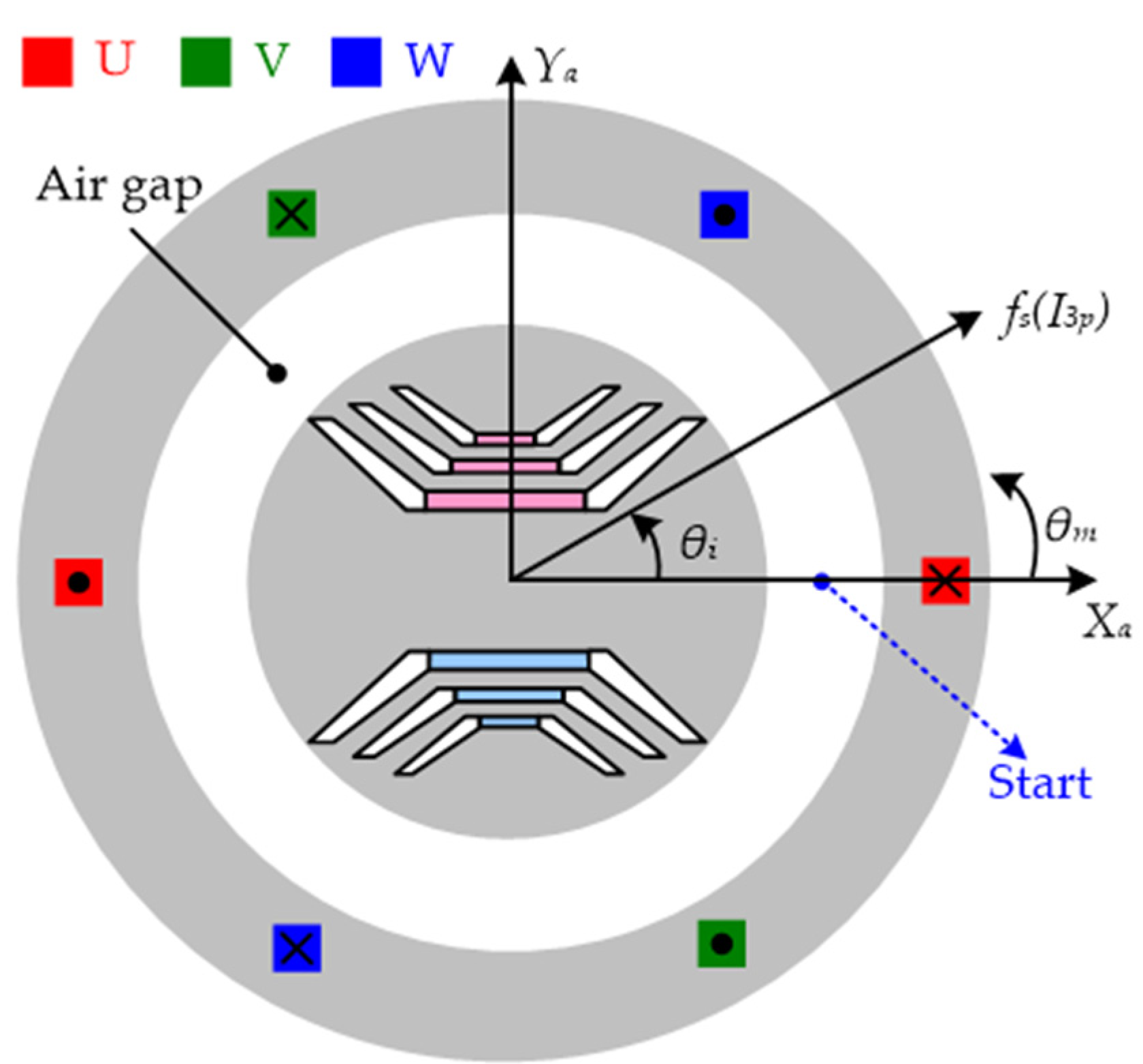
Funding

This research was funded by the National Science and Technology Council of Taiwan, under grand number MOST107-2221-E-027-081-MY3.

Data Availability Statement

Data are contained within the article.

Conflicts of Interest

The authors declare no conflict of interest.

References

  1. Li, X.; Sun, Z.; Sun, W.; Guo, L.; Wang, H. Design of Permanent Magnet-Assisted Synchronous Reluctance Motor with Low Torque Ripple. World Electr. Veh. J. 2023, 14, 82. [Google Scholar] [CrossRef]
  2. Mohammadi, A.; Mirimani, S.M. Design of a Novel PM-Assisted Synchronous Reluctance Motor Topology Using V-Shape Permanent Magnets for Improvement of Torque Characteristic. IEEE Trans. Energy Convers. 2022, 30, 424–432. [Google Scholar] [CrossRef]
  3. Degano, M.; Murataliyev, M.; Shuo, W.; Barater, D.; Buticchi, G.; Jara, W.; Bianchi, N.; Galea, M.; Gerada, C. Optimised Design of Permanent Magnet Assisted Synchronous Reluctance Machines for Household Appliances. IEEE Trans. Energy Convers. 2021, 36, 3084–3095. [Google Scholar] [CrossRef]
  4. Taghavi, S.; Pillay, P. A Sizing Methodology of the Synchronous Reluctance Motor for Traction Applications. IEEE J. Emerging Sel. Top. Power Electron. 2014, 2, 329–340. [Google Scholar] [CrossRef]
  5. Mahmoud, H.; Bianchi, N. Eccentricity in Synchronous Reluctance Motors—Part I: Analytical and Finite-Element Models. IEEE Trans. Energy Convers. 2015, 30, 745–753. [Google Scholar] [CrossRef]
  6. Mahmoud, H.; Bianchi, N. Eccentricity in Synchronous Reluctance Motors—Part II: Different Rotor Geometry and Stator Windings. IEEE Trans. Energy Convers. 2015, 30, 754–760. [Google Scholar] [CrossRef]
  7. Bacco, G.; Bianchi, N.; Mahmoud, H. A Nonlinear Analytical Model for the Rapid Prediction of the Torque of Synchronous Reluctance Machines. IEEE Trans. Energy Convers. 2018, 33, 1539–1546. [Google Scholar] [CrossRef]
  8. Bianchi, N.; Bolognani, S.; Bon, D.; Dai PrÉ, M. Rotor Flux-Barrier Design for Torque Ripple Reduction in Synchronous Reluctance and PM-Assisted Synchronous Reluctance Motors. IEEE Trans. Ind. Appl. 2009, 45, 921–928. [Google Scholar] [CrossRef]
  9. Gallicchio, G.; Di Nardo, M.; Palmieri, M.; Marfoli, A.; Degano, M.; Gerada, C.; Cupertino, F. High Speed Permanent Magnet Assisted Synchronous Reluctance Machines—Part I: A General Design Approach. IEEE Trans. Energy Convers. 2022, 37, 2556–2566. [Google Scholar] [CrossRef]
  10. Bianchi, N.; Bolognani, S.; Bon, D.; Dai PrÉ, M. Torque Harmonic Compensation in a Synchronous Reluctance Motor. IEEE Trans. Energy Convers. 2008, 23, 466–473. [Google Scholar] [CrossRef]
  11. Pelich, R.; Chini, M.; Hostache, R.; Matgen, P.; Delgado, J.M.; Sabatino, G. Design of Rotating Electrical Machines; John Wiley & Sons, Inc.: Hoboken, NJ, USA, 2009; ISBN 978-0-470-74008-8. [Google Scholar]
  12. Say, M.G. Alternating Current Machines; John Wiley & Sons, Inc.: Hoboken, NJ, USA, 1976; ISBN 9780470151334. [Google Scholar]
  13. Novotny, D.W.; Lipo, T.A. Vector Control and Dynamics of AC Drives; The Clarendon Press: Oxford, UK, 1998; ISBN 9784485665213. [Google Scholar]
  14. Liwschitz-Garik, M.; Whipple, C.C. Electric Machinery; Van Nostrand: New York, NY, USA, 1960. [Google Scholar]
  15. Magnussen, F.; Sadarangani, C. Winding factors and Joule losses of permanent magnet machines with concentrated windings. In Proceedings of the IEEE International Electrical Machines and Drives Conference, Madison, WI, USA, 1–4 June 2003; pp. 333–339. [Google Scholar]
  16. Miao, Y.; Ge, H.; Preindl, M.; Ye, J.; Cheng, B.; Emadi, A. MTPA Fitting and Torque Estimation Technique Based on a New Flux-Linkage Model for Interior-Permanent-Magnet Synchronous Machines. IEEE Trans. Ind. Appl. 2017, 53, 5451–5460. [Google Scholar] [CrossRef]
  17. Gallardo, C.; Tapia, J.A.; Degano, M.; Mahmoud, H. Accurate Analytical Model for Synchronous Reluctance Machine with Multiple Flux Barriers Considering the Slotting Effect. IEEE Trans. Magn. 2022, 58, 1–9. [Google Scholar] [CrossRef]
  18. Yan, D.; Chen, Z.; Wang, Z.; Wang, H.; Shi, T.; Xia, C. The Torque Ripple Reduction in PMAREL Machine Using Time-Space Harmonics Analysis of Air-Gap Flux Density. IEEE Trans. Ind. Electron. 2022, 69, 2390–2401. [Google Scholar] [CrossRef]
  19. Murataliyev, M.; Degano, M.; Galea, M. A Novel Sizing Approach for Synchronous Reluctance Machines. IEEE Trans. Ind. Electron. 2021, 68, 2083–2095. [Google Scholar] [CrossRef]
  20. Degano, M.; Mahmoud, H.; Bianchi, N.; Gerada, C. Synchronous reluctance machine analytical model optimization and validation through finite element analysis. In Proceedings of the 2016 XXII International Conference on Electrical Machines (ICEM), Lausanne, Switzerland, 4–7 September 2016; pp. 585–591. [Google Scholar]
  21. Chai, F.; Hu, H.; Geng, L. Theoretical analysis of torque performance in permanent magnet-assisted synchronous reluctance motor. In Proceedings of the 2017 20th International Conference on Electrical Machines and Systems (ICEMS), Sydney, NSW, Australia, 11–14 August 2017; pp. 1–6. [Google Scholar]
  22. Song, I.-S.; Jo, B.-W.; Kim, K.-C. Analysis of an IPMSM Hybrid Magnetic Equivalent Circuit. Energies 2021, 14, 5011. [Google Scholar] [CrossRef]
  23. Wang, L.; Lu, S.; Chen, Y. Two-Dimensional Analytical Models for Cogging Torque Prediction in Interior Permanent Magnet Machine. Machines 2023, 11, 233. [Google Scholar] [CrossRef]
  24. Gao, J.; Li, C.; Dai, L.; Huang, S.; Xu, W. A Practical Analytical Expression and Estimation for Average Torque of High Saturation Permanent Magnet Synchronous Motor for Special Vehicles. IEEE Trans. Veh. Technol. 2023, 72, 357–366. [Google Scholar] [CrossRef]
  25. Huang, L.R.; Feng, J.H.; Guo, S.Y.; Shi, J.X.; Chu, W.Q.; Zhu, Z.Q. Analysis of Torque Production in Variable Flux Reluctance Machines. IEEE Trans. Energy Convers. 2017, 32, 1297–1308. [Google Scholar] [CrossRef]
  26. Gaussens, B.; De la Barrière, O.; Hoang, E.; Saint-Michel, J.; Manfe, P.; Lécrivain, M.; Gabsi, M. Magnetic Field Solution in Doubly Slotted Airgap of Conventional and Alternate Field-Excited Switched-Flux Topologies. IEEE Trans. Magn. 2013, 49, 5083–5096. [Google Scholar] [CrossRef]
  27. Maroufian, S.S.; Pillay, P. Torque Characterization of a Synchronous Reluctance Machine Using an Analytical Model. IEEE Trans. Transp. Electrif. 2018, 4, 506–516. [Google Scholar] [CrossRef]
  28. Ionel, D.M.; Popescu, M.; McGilp, M.I.; Miller, T.J.E.; Dellinger, S.J. Assessment of torque components in brushless permanent-magnet machines through numerical analysis of the electromagnetic field. IEEE Trans. Ind. Appl. 2015, 41, 1149–1158. [Google Scholar] [CrossRef]
  29. Spargo, C.M.; Mecrow, B.C.; Widmer, J.D. A Seminumerical Finite-Element Postprocessing Torque Ripple Analysis Technique for Synchronous Electric Machines Utilizing the Air-Gap Maxwell Stress Tensor. IEEE Trans. Magn. 2014, 50, 1–9. [Google Scholar] [CrossRef]
  30. Liang, J.; Dong, Y.; Sun, H.; Liu, R.; Zhu, G. Flux-Barrier Design and Torque Performance Analysis of Synchronous Reluctance Motor with Low Torque Ripple. Appl. Sci. 2022, 12, 3958. [Google Scholar] [CrossRef]
  31. Sun, Y.; Bianchi, N.; Ji, J.; Zhao, W. Improving Torque Analysis and Design Using the Air-Gap Field Modulation Principle for Permanent-Magnet Hub Machines. Energies 2023, 16, 6214. [Google Scholar] [CrossRef]
  32. Sadarangani, C. Electrical Machines-Design and Analysis of Induction and Permanent Magnet Motors; Royal Inst. of Technology: Stockholm, Sweden, 2006. [Google Scholar]
  33. Han, S.; Jahns, T.M.; Soong, W.L.; Güven, M.K.; Illindala, M.S. Torque Ripple Reduction in Interior Permanent Magnet Synchronous Machines Using Stators with Odd Number of Slots Per Pole Pair. IEEE Trans. Energy Convers. 2010, 25, 118–127. [Google Scholar] [CrossRef]
  34. Li, Z.F.; Huang, M.S.; Huang, L.W. Analytical Approach to Estimate Torque Characterization of Synchronous Motors Assisted by FEA. In Proceedings of the 2022 International Power Electronics Conference (IPEC-Himeji 2022-ECCE Asia), Himeji, Japan, 15–19 May 2022; pp. 2721–2727. [Google Scholar]
  35. Laldin, O.; Sudhoff, S.D.; Pekarek, S. Modified Carter’s Coefficient. IEEE Trans. Energy Convers. 2015, 30, 1133–1134. [Google Scholar] [CrossRef]
  36. Yin, H.; Zhang, H.; Hua, W.; Su, P. Improved Open-Circuit Airgap Field Model for FSCW-STPM Machines Considering PM-MMF Fluctuation. IEEE Trans. Ind. Electron. 2022, 69, 5547–5556. [Google Scholar] [CrossRef]
  37. Amirkhani, M.; Kondelaji, M.A.J.; Ghaffarpour, A.; Mirsalim, M.; Vaez-Zadeh, S. Study of Boosted Toothed Biased Flux Permanent Magnet Motors. IEEE Trans. Transp. Electrif. 2022, 8, 2549–2564. [Google Scholar] [CrossRef]
  38. Bianchi, N.; Mahmoud, H. An Analytical Approach to Design the PM in PMAREL Motors Robust Toward the Demagnetization. IEEE Trans. Energy Convers. 2016, 31, 800–809. [Google Scholar] [CrossRef]
  39. Boazzo, B.; Vagati, A.; Pellegrino, G.; Armando, E.; Guglielmi, P. Multipolar Ferrite-Assisted Synchronous Reluctance Machines: A General Design Approach. IEEE Trans. Indu. Electron. 2015, 62, 832–845. [Google Scholar] [CrossRef]
  40. Ooi, S.; Morimoto, S.; Sanada, M.; Inoue, Y. Performance Evaluation of a High-Power-Density PMASynRM with Ferrite Magnets. IEEE Trans. Ind. Appl. 2013, 49, 1308–1315. [Google Scholar] [CrossRef]
  41. Morimoto, S.; Ooi, S.; Inoue, Y.; Sanada, M. Experimental Evaluation of a Rare-Earth-Free PMASynRM with Ferrite Magnets for Automotive Applications. IEEE Trans. Ind. Electron. 2014, 61, 5749–5756. [Google Scholar] [CrossRef]
  42. Wang, Y.; Bianchi, N.; Qu, R. Comparative Study of Non-Rare-Earth and Rare-Earth PM Motors for EV Applications. Energies 2022, 15, 2711. [Google Scholar] [CrossRef]
  43. Qi, J.; Zhu, Z.Q.; Yan, L.; Jewell, G.W.; Gan, C.; Ren, Y.; Brockway, S.; Hilton, C. Effect of Pole Shaping on Torque Characteristics of Consequent Pole PM Machines. IEEE Trans. Ind. Appl. 2022, 58, 3511–3521. [Google Scholar] [CrossRef]
Figure 1. Simplified schematic of a synchronous motor.
Energies 16 07832 g001
Figure 2. Lorentz force in a wire of a rotor.
Energies 16 07832 g002
Figure 3. Types of flux-density-produced mechanisms in the air gap: (a) flux density produced by the current (Bs); (b) flux density produced by the PM (BPM); (c) flux density produced by the rotor (Br); and (d) sum of BPM and Br (Bg).
Energies 16 07832 g003
Figure 4. Relationship between θi and the generated flux waveform (Bs).
Energies 16 07832 g004
Figure 5. Phasor diagrams of a synchronous motor: (a) SPMSM; (b) SynRM; and (c) IPMSM.
Energies 16 07832 g005
Figure 6. Flux-density-produced mechanism in the air gap under ideal SPMSM: (a) Bs; (b) BPM; and (c) sum of BPM and Bs (Bg).
Energies 16 07832 g006
Figure 7. Winding function of each phase.
Energies 16 07832 g007
Figure 8. Waveforms of Bs at 9.4 Arms: (a) θi = 0° and (b) θi = 60°.
Energies 16 07832 g008
Figure 9. The characteristics of BPM without a stator effect: (a) flux path and (b) waveform of BPM.
Energies 16 07832 g009
Figure 10. Waveforms of Bg at 9.4 Arms: (a) θi = 0° and (b) θi = 60°.
Energies 16 07832 g010
Figure 11. Flowchart of the proposed torque estimation method.
Energies 16 07832 g011
Figure 12. Waveform of Bsl under the rated current of 9.4 Arms (θi = 0° and 30°).
Energies 16 07832 g012
Figure 13. Magnetic circuit in a 1/4 motor model: (a) flux path obtained when considering the effect of the stator slot and (b) constructed equivalent reluctance circuit.
Energies 16 07832 g013
Figure 14. Curve of ksat versus I3p.
Energies 16 07832 g014
Figure 15. Symmetrical half-slot model in which the rotor effect is not considered.
Energies 16 07832 g015
Figure 16. Bs Waveform when considering the slot effect (I3p = 20 Apeak at θi = 0° and 60°).
Energies 16 07832 g016
Figure 17. Sketch of the rotor structure and direction of flux generated by the stator.
Energies 16 07832 g017
Figure 18. Fitting results for the rotor: (a) kr,1(θi) and (b) θkr,1(θi).
Energies 16 07832 g018
Figure 19. Rotor geometry and equivalent circuit of an i-layer rotor: (a) full model and (b) simplified model.
Energies 16 07832 g019
Figure 20. Equivalent circuit of the rotor of the proposed PMASynRM with three-layer barriers.
Energies 16 07832 g020
Figure 21. Waveforms of BPM obtained through FEA simulation and the proposed method.
Energies 16 07832 g021
Figure 22. Phasor diagram of the rotor of the proposed PMASynRM.
Energies 16 07832 g022
Figure 23. MTPA curves of the two proposed motors at 9.4 Arms.
Energies 16 07832 g023
Figure 24. Flux density distribution under different phase currents when θi = 0° and different phase currents: (a) 1 Arms and (b) 9.4 Arms.
Energies 16 07832 g024
Figure 25. Linear and nonlinear flux densities in the air gap under different currents when θi = 0°.
Energies 16 07832 g025
Figure 26. Flux density distribution when considering the stator slot effect.
Energies 16 07832 g026
Figure 27. Waveform of Bs obtained using different methods when Ip = 9.4 Arms and θi = 60°.
Energies 16 07832 g027
Figure 28. Flux distribution of Br under the rated current when Ip = 9.4 Arms and different leading current angle: (a) θi = 0° and (b) θi = 90°.
Energies 16 07832 g028
Figure 29. Waveform of Br under different θi values and an Ip value of 9.4 Arms when θi = 0° and 60°.
Energies 16 07832 g029
Figure 30. Waveforms of Bg and Br at 9.4 Arms when θi = 60°.
Energies 16 07832 g030
Figure 31. Results obtained for sin (θgs,1) and sin (θrs,1) through FEA under different θi values.
Energies 16 07832 g031
Figure 32. Output torque of the PMASynRM obtained through FEA. (a) θi = 30° and (b) θi = 60°.
Energies 16 07832 g032
Figure 33. Average output torque obtained through FEA and the proposed method.
Energies 16 07832 g033
Figure 34. Parts of the PMASynRM and the complete assembled motor: (a) rotor and stator; (b) ferrite PM; (c) winding; and (d) complete assembled motor.
Energies 16 07832 g034
Figure 35. Experimental setup for testing the proposed PMASynRM.
Energies 16 07832 g035
Figure 36. Experimental torque values obtained under different conditions: (a) relationships between the current magnitude, the current angle, and the output torque (SPWM control and rotation speed of 1200 rpm); (b) θi = 30°, 1200rpm; and (c) θi = 60°, 1200 rpm.
Energies 16 07832 g036
Table 1. Key specifications and cross-sections of three types of synchronous motors.
NameIdeal SPMSMSynRMPMASynRM
GeometryEnergies 16 07832 i001Energies 16 07832 i002Energies 16 07832 i003
Rated power 6.7 kW4.0 kW4.5 kW
Rated phase current9.4 Arms9.4 Arms9.4 Arms
Inner/outer diameter of rotor0.0/94.4 mm31.0/94.4 mm31.0/94.4 mm
Inner/outer diameter of stator95.0/160.0 mm95.0/160.0 mm95.0/160.0 mm
Air gap 0.3 mm0.3 mm0.3 mm
PM materialRare earth (N38UH)Without PMFerrite (NMF7D)
Winding Series (25 N)Series (25 N)Series (25 N)
Silicon steel50CS47050CS47050CS470
Stack length 150.0 mm150.0 mm150.0 mm
Table 2. The key parameters and proposed calculation results of a SPMSM torque under different θi.
ParametersValues
θi60°
ks11
Bg,11.39 T/157.7°0.88 T/162.4°
Bs,10.52 T/90.0°0.52 T/30.0°
BPM,11.29 T/180.0°1.29 T/180.0°
rg47.35 mm47.35 mm
θgs,167.7°132.4°
Torque (Cal)54.6 Nm27.6 Nm
Torque (FEA)53.1 Nm26.3 Nm
Error2.8%4.9%
Table 3. Geometric data of the proposed PMASynRM.
ParameterValueDescription
Brem0.43 TRemanence flux density of ferrite PM.
g0.3 mmAir gap length.
lstk150.0 mmStack length of motor.
θbs,l116.9°Half angle of the layer 1, layer 2, and layer 3 barrier at start point.
θbs,l226.1°
θbs,l333.7°
θbe,l120.8°Half angle of the layer 1, layer 2, and layer 3 barrier at end point.
θbe,l230.3°
θbe,l337.7°
wPM,l110.6 mmPM width of layer 1, layer 2, and layer 3.
wPM,l214.5 mm
wPM,l320.0 mm
lPM,l12.9 mmPM length of layer 1, layer 2, and layer 3.
lPM,l24.3 mm
lPM,l34.3 mm
wb,l17.9 mmSide width of the layer 1, layer 2, and layer 3 barrier.
wb,l213.5 mm
wb,l316.4 mm
lb,l13.1 mmSide length of the layer 1, layer 2, and layer 3 barrier.
lb,l23.7 mm
lb,l34.9 mm
Table 4. Parameters of the phase diagram used for the flux density calculation.
SimulationProposed Calculation
θi30°60°30°60°
BPM,10.150.16
θPM,1181.9°180.0°
Br,11.090.901.100.91
θr,185.479.685.279.6
Bg,11.100.911.100.90
θg,193.089.193.589.7
Table 5. Torque calculation using different methods.
ParameterValue
is9.4 Arms
θi60°
P4
μ04π × 10−7
g0.3 mm
rg47.4 mm
lstk150 mm
Motor typeSynRMPMASynRM
MethodFull FEAProposedFull FEAProposed
ksat0.300.300.300.30
Bs,11.16 T1.16 T1.16 T1.16 T
Bg,1NaNNaN0.89 T0.90 T
θgs,159.1°59.7°
Br,10.90 T0.91 TNaNNaN
θrs,149.6°49.6°
T127.9 Nm28.4 Nm31.3 Nm31.8 Nm
Torque error1.8%1.6%
Table 6. Air gap flux density caused by the barrier effect.
θiBr,1θr,1
01.0990.0
301.0585.4
600.9179.6
900.230.0
Table 7. Quantitative comparison of the average torque results under different currents.
Average Torque (Nm)Proposed CalculationFEAExperiment (300 rpm)Experiment (1200 rpm)
Rated current50%/75%/100%50%/75%/100%50%/75%/100%50%/75%/100%
θi30°11.2/17.0/23.810.7/17.4/23.210.0/16.6/23.110.2/16.8/23.3
35°12.0/18.5/26.311.6/19.0/25.610.7/18.0/25.311.0/18.2/25.4
40°12.8/19.9/28.312.4/20.4/27.611.4/19.4/27.511.5/19.4/27.3
45°13.2/21.1/30.012.8/21.5/29.111.8/20.4/28.811.7/20.3/28.8
50°13.1/21.9/31.113.0/22.3/30.511.8/20.9/30.111.6/20.8/30.0
55°12.7/22.4/31.912.6/22.5/31.111.6/21.1/30.711.2/20.8/30.3
60°12.0/22.1/31.811.7/21.9/31.310.9/20.6/30.410.5/20.3/29.7
Disclaimer/Publisher’s Note: The statements, opinions and data contained in all publications are solely those of the individual author(s) and contributor(s) and not of MDPI and/or the editor(s). MDPI and/or the editor(s) disclaim responsibility for any injury to people or property resulting from any ideas, methods, instructions or products referred to in the content.

