Abstract
The exploration and development of new hydrocarbon deposits face increasing challenges, primarily driven by the shift away from hydrocarbons towards renewable energy sources like shallow geothermal deposits, wind farms, and photovoltaics. This shift necessitates finding solutions that minimize environmental impact and enable increased energy extraction from existing or decommissioned fields and wells. This paper explores the possibility of excavating from potentially depleted fields, where a significant portion (up to 85%) of the reservoir’s resources remain unrecoverable due to low reservoir energy. To address this, secondary and tertiary exploitation methods are proposed involving the supply of external energy to increase the pressure in the reservoir layer, thereby enhancing resource exploitation. One of the suggested tertiary methods involves reaming the deposit with multiple small-diameter radial holes using a hydraulic drilling nozzle. The entire process comprises several key components, including the coiled tubing unit (CTU), high-pressure flexible hose, window drilling kit for casing pipe, kit for positioning the exit of the hydraulic drilling head from the casing pipe, anchor, and hydraulic drilling head attached to the end of the high-pressure flexible hose. This method aims to increase the contact between the reservoir layer and the wellbore, potentially leading to an increase in or initiation of exploitation in certain deposit scenarios. The described method presents an environmentally friendly approach, eliminating the need for drilling new boreholes and offering cost-effective access to resources in decommissioned deposits with insufficient reservoir energy for self-exploitation. The applicability of this method to extract methane from coalbed seams is also mentioned in this article. In a separate article, the authors detail the design of a hydraulic drilling nozzle specifically for reaming the reservoir layer.
1. Introduction
The persistent demand for crude oil distillates has driven continuous advancements in extraction technology. The increasing need to explore exploitable hydrocarbon deposits, often located at greater depths, has further intensified the development of drilling processes, machinery, and equipment. In response, there is a growing emphasis on multidirectional solutions and innovative rotary drilling techniques and technologies.
This focus extends beyond just enhancing the technical capabilities of drilling equipment. It also addresses the crucial aspect of depleting existing hydrocarbon reservoirs that are not economically viable for self-exploitation. As the industry explores new possibilities, especially in obtaining natural gas from coal seams, attention is directed towards the economic feasibility of capturing variable gas from such deposits.
In essence, the evolution of extraction technology is not only driven by the demand for crude oil distillates but is also fueled by the need for sustainable, efficient, and economically viable solutions to access hydrocarbon resources, including unconventional sources like gas in coal seams.
Based on a literature analysis conducted during the exploration of new solutions for mineral deposits located in unconventional settings for hydrocarbon exploitation, a concept for a hydraulic drilling nozzle head with a continuous liquid stream was proposed. The concept underwent thorough testing during research and laboratory work. This article primarily focuses on determining the geometry of the openings in the hydraulic drilling nozzle.
The investigation delves into several key aspects:
- This study explores how the effectiveness of the jet is influenced by the distance between the hydraulic drilling nozzle toolface and the rock formation being cut.
- Effective range of the jet: This research considers the effective range of the jet in relation to the diameter of the openings in the nozzle.
- Determining the discharge velocity from the hydraulic drilling nozzle openings is crucial in understanding the performance of the system.
- This study aims to determine the contraction coefficients of the rotary nozzle, providing insights into the hydraulic energy transferred by the working fluid.
These findings serve as a foundation for future research, emphasizing the need for a comprehensive understanding of the hydraulic energy involved in the drilling process using the proposed hydraulic drilling nozzle.
2. Recoverable Reserves of Natural Gas from Deposits Located in Coal Seams
Recoverable reserves of natural gas from coal seams are influenced by a combination of geological, technological, economic, and environmental factors. Advances in extraction technologies and a better understanding of coal seam characteristics continue to play a crucial role in unlocking and maximizing these reserves.
The presence of methane in coal deposits is a result of the coal-formation process [1]. It is estimated that up to 200 m3 of gas is produced during the formation of one ton of coal [2]. Much of this gas, containing about 90% methane (CH4), is naturally released to the surface through fractures and micro cracks in coal seams. However, a substantial portion of the gas remains trapped in the coal seams in an adsorbed form [2]. It is important to note that these are considered balance resources. Methane, when released into the atmosphere along with carbon dioxide, contributes significantly to disrupting the environmental balance and is a major contributor to global warming [3]. The impact of methane is up to 22 times greater than that of carbon dioxide. Therefore, planning drilling activities for extracting tight gas from coal units is a complex, multiparameter process.
It is worth mentioning the potential opportunities that could arise from the exploitation of existing wells in coal basins. In Poland, there are three significant coal-bearing areas: GZW (Upper Silesian Coal Basin), DZW (Lower Silesian Coal Basin), and LZW (Lublin Coal Basin) [1]. Among these, the Lublin Coal Basin is considered to have the smallest prospects for coal seam methane production. On the other hand, the GZW has the highest prospects for methane exploitation, with estimated recoverable methane resources reaching 150 billion cubic meters [1]. The exploration and utilization of methane from these coal basins could play a crucial role in energy production while considering the environmental impact and global warming concerns associated with methane emissions.
The extraction of natural gas involves a two-phase process. In the first phase, a directional J-type well with a long horizontal section will be drilled. Once this is completed, a window in the casing cemented above the coal bed horizon will be created. In the second phase, a hydraulic rotary nozzle will be inserted through the window, and hydroprobing of small-diameter boreholes at various angles towards the deposit layer, such as coal, will be carried out. This approach aims to enhance the contact between the deposit and the base hole through the horizontal hole, from which small-diameter radial holes will be drilled. Radial drilling is considered an effective method for the stimulation, production, and exploration of oil and gas [4,5]. It is a revolutionary technology for efficiently developing unconventional resources [6]. The technique involves creating several small-diameter drain holes from the well in a relatively short time, providing a fast method to rehabilitate and optimize oil and gas wells using high-pressure fluid at selected depths [7]. The ongoing development of drilling technologies for hydrocarbon deposits has always focused on finding solutions to reduce drilling costs while increasing operational efficiency [8,9]. By eliminating the need for a vertical section, the proposed radial hydraulic drilling technology can reduce the cost of drilling a single production hole. Moreover, adapting existing boreholes to this technology offers financial benefits by reducing decommissioning costs and directly increasing operating profits generated from the recovered reservoir medium.
The ability to drill multiple radial boreholes hydraulically from a horizontal borehole provides control over the volume of reservoir medium inflow to the main borehole, thereby increasing the quantitative depletion rate of the deposit. The proposed hydraulic rotary nozzle technology can potentially find successful applications in other industries, following proper consideration of the technology requirements and adaptation to specific tasks, such as cleaning pipelines, degassing mine shafts, injecting sealing fluids into gallery ceiling layers, and creating freeze holes, among other applications.
3. The Idea of Using Small-Diameter Radial Boreholes as an EOR Method for Deposits with Low Reservoir Energy and Destined for Decommissioning
The concept of using small-diameter radial boreholes as an enhanced oil recovery (EOR) method for deposits with low reservoir energy and those destined for decommissioning involves drilling multiple radial wells from an existing drilled and cased well. It is estimated that between 75% to 85% of all known hydrocarbon discoveries remain in the ground [10]. This method is particularly relevant for potentially depleted fields where a significant portion of the reservoir’s resources is not recoverable due to low reservoir energy. One-third of the oil in fields can be extracted through primary methods, harnessing the natural energy of the reservoir and irrigation [11]. Consequently, significant amounts of oil, often up to 75% of the initial reserves, remain untapped. While the extraction efficiency can be enhanced with secondary and tertiary methods, collectively known as enhanced oil recovery (EOR), their high costs limit widespread adoption. In Poland, primary methods prevail, leaving substantial untapped oil in ostensibly depleted fields [11].
The terms “primary extraction”, “secondary extraction”, and “tertiary methods” (EOR) delineate the sequential progression of oil production. Primary methods leverage the reservoir’s natural energy, while secondary methods come into play when energy becomes depleted or insufficient. Injecting water or gas into the reservoir, displacing the medium, is a common approach to replenish energy and boost production. When secondary methods fall short, additional energy forms are introduced to aid extraction. What sets tertiary methods apart is their supplementary nature, substituting or augmenting the natural displacement mechanisms found in primary and secondary methods. Enhanced oil flow is achieved through methods such as applying heat, initiating chemical reactions, or altering oil properties, facilitating its movement through the reservoir [9,11]. The diminishing number of new discoveries of conventional hydrocarbon deposits within our country underscores the need to explore new avenues for the oil industry, aiming to sustain or boost extracted reserves and maintain ongoing production [12]. Two pivotal development opportunities emerge: firstly, enhancing production from existing fields through the application of secondary and tertiary extraction methods (EOR), and secondly, tapping into hydrocarbons from unconventional deposits. Elevating production from conventional deposits mandates the adoption of advanced access and extraction technologies to optimize the use of recognized and accessible resources [13].
The range of these efforts extends from the conversion of existing vertical wells into horizontal and multiwells to the utilization of production intensification and advanced methods [9,12]. The utilization of horizontal wells in the exploitation of hydrocarbon deposits has been on the rise since the early 1980s. The augmentation of reservoir medium production through horizontal boreholes has primarily been linked to the exploitation of deposits with a thin thickness of less than 15 m and those with low permeability (tight gas). An essential determinant of the efficacy of vertical boreholes is the permeability of the medium in the horizontal plane. The output from a horizontal hole is significantly higher when drilled perpendicular to the axis of maximum permeability compared to drilling in the opposite direction. Directional drilling technology facilitates the drilling of boreholes in the desired direction, thereby enhancing the prospects of judiciously employing EOR methods.
4. Technology of Reaming Deposits with Small-Diameter Radial Holes
Currently, jet-nozzle drilling technology is widely employed for cutting, hydraulic jet drilling, and pipeline cleaning, thanks to the potential for high energy concentration in the jet. Figure 1 illustrates a general scheme of the equipment and tools used for creating radial holes with a high-energy liquid jet flowing through a nozzle at high pressure. This solution is commonly found in various publications and some patents [5,6,9,11,13,14,15]. Although individual solutions may vary in their technical details, the hydraulic jet drilling technique is generally employed when drilling radial boreholes.

Figure 1.
Small-diameter radial bore deposit reaming technology. 1: high-pressure line guide, 2: casing pipe, 3: deflector, 4: deflector channel, 5: high-pressure flexible line, 6: pacer, 7: deflector anchor, 8: rotary head, 9: directional nozzles for annular space clearing, 10: normal-diameter borehole, 11: drilled geological formation, 12: small-diameter radial boreholes.
The drilled sections are typically horizontal, with lengths ranging from 100 to 300 m and diameters between 40 and 60 mm, or lengths of 10–100 m with a radius of 20–50 mm [16]. In another article, the authors described drilling horizontal radial channels out from an existing wellbore up to 100 m in any direction with a 30–50 mm diameter using high-pressure fluid [10]. The considerable variation in horizontal section lengths is influenced by specific demands for the drainage zone’s length. The absence of a nominal borehole diameter is attributed to the nature of nozzle hydrofracturing and the wellbore medium’s structure, incorporating numerous technological factors and reservoir rock parameters. Figure 1 provides an enlarged diagram of the nozzle and conduit in the borehole.
Rising production costs necessitate investments in innovative solutions [16], leading to the overcoming of various barriers and challenges during the design and application stages [17]. The small-diameter radial wells discussed in this article, drilled using a hydraulic rotary head from the base well, aim to enhance contact between the well and the reservoir, contributing to the intensified extraction of reservoir resources. Formed radial laterals, distributed in one or multiple layers, can penetrate the near-well damage zone and communicate with the formation far from the main well [16,17,18,19]. It can also be a viable alternative for traditional perforation and extended horizontal perforation, reaching beyond the damaged zone near the wellbore [16].
4.1. Technological Solutions
The proposed technology envisions utilizing existing wells as base wells, initiating the drilling of multiple small-diameter wells (25–60 mm) at a length of 100–250 m (Figure 1). These wells will diverge in various directions, each having distinct lengths within a single well [20].
The process generally consists of the following steps:
- pulling out production equipment from the well and existing downhole equipment.
- cleaning the borehole to ensure optimal conditions for drilling.
- casing on the production tubing or drill pipe to the specified depth of the downhole set, enabling the creation of a window in the casing pipe.
- making a window in the casing with a window-cutting tool.
- arming the capillary with a flexible pressure hose with a nozzle and launching into the deflector, starting drilling to the set length.
- retracting the drilling set from the hole with simultaneous flushing of the hole from the borings.
- repositioning and redrilling: pulling out the drilling set, unhooking the anchor, changing the orientation of the deflector, fastening the anchor, and drilling another window and borehole if required.
- completing the operation by pulling out the downhole set and fastening the production equipment to the well.
The outlined technology concept facilitates the rejuvenation of retired wells. The rotary head, powered by liquid jets for extraction, stands out as a key component in this technology. Understanding the initiation and propagation of fractures along the radial borehole is crucial for the successful design of all equipment components and seamless operation throughout the entire process. Current solutions available in the market typically involve drilling a vertical base hole with a subsequent horizontal section. From this base horizontal hole, branch holes are drilled. Another technology focuses on creating multiple multilateral, multidiameter holes originating from the vertical section of the base hole. In a patent from 2006 [21], the author outlines a method involving a vertical section followed by a horizontal borehole as the primary base borehole, with departures in the direction of the penetrated layer. All drilled holes are in one plane for each main hole and are drilled as successive horizontal holes from the base hole.
A patent described in US 2011/0005762 A1 [22] details a technology for drilling sets of boreholes offset at an angle of no more than 90° with an azimuth in the range of 9–18°/100 feet of the drilled hole. Another patent application, number US 2017/0030180 A1 [23], involves drilling a drainage well (several drilling proposals) in the fractured zone of the reservoir formed after the hydraulic fracturing process in the reservoir zone. The drainage well is drilled over the primary well drilled to access the reservoir zone. In yet another patent application [24], the authors describe a method for accessing methane located in coal seams by drilling an access well cased with casing pipes in the 100–1500 m depth range over a coal seam.
The technological solution presented in this article aims to facilitate the access and extraction of methane from deposits within coal seams. The process involves drilling a borehole to access methane deposits located in coal seams. This is achieved by initially drilling a horizontal borehole in the coal overburden layer. Subsequently, small-diameter boreholes are drilled into the coal seam using a hydraulic drilling nozzle (Figure 2, Figure 3 and Figure 4) from the casing windows through the deposit. The entire process constitutes a comprehensive method that encompasses the drilling and completion of the borehole, adhering to established borehole construction techniques.
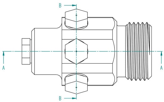
Figure 2.
View of the head for conducting research measurements of the liquid stream flowing out of the mining holes.

Figure 3.
Cross-section A-A of the head for conducting research measurements of the liquid stream flowing out of the mining holes.
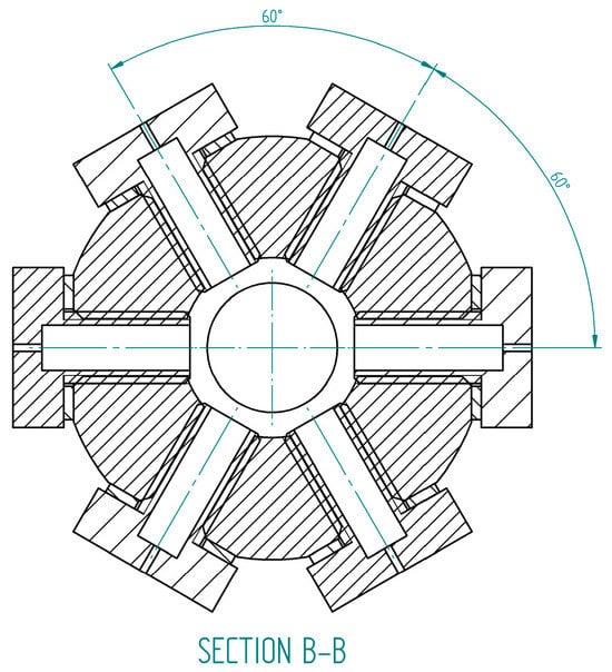
Figure 4.
B-B cross-section of the head for conducting research measurements of the liquid stream flowing out of the mining holes.
Figure 1 illustrates the described technology along with its main components. The key components and their functions are as follows:
- The deflector provides direction to the rotary head. It is secured to the horizontal section of the existing wellbore using a support conduit, which can be either production tubing or drill pipe, depending on the specific components employed in the particular wellbore.
- The rotary head is oriented at an angle to the existing horizontal section of the drill hole through the deflector channel of the deflector, which is fastened to the casing pipes and anchored using an anchor.
- The anchor secures the deflector to the casing pipes, ensuring stability during the drilling process.
- The rotary head is mounted on the end of the high-pressure flexible tubing, which is connected to the drilling fluid circulation system through the coiled tubing (CT).
- The packer is positioned in front of the deflector anchor; the packer facilitates separation from the rest of the horizontal borehole.
This configuration allows for controlled and directed drilling from the existing horizontal wellbore, enhancing access to resources in the geological formation. The anchor, deflector, and packer contribute to the stability and effectiveness of the drilling process.
4.2. Benefits of Technology Used in Industry
The technology and equipment set developed within the framework of the MiniDrill project, conducted at the Drilling Oil and Gas Faculty, Drilling and Geoengineering Department, particularly the hydraulic rotary head, will facilitate:
- obtaining data for making precise decisions regarding reconstruction, reaming, implementing costly intensification procedures, or decommissioning a low-productivity well.
- a distinctive approach to gathering data on the actual anisotropy of the reservoir layer for a directional drilling project (depth, direction). This is aimed at achieving maximum effectiveness and minimizing the risk of misguided investments.
- a cost-effective means of enhancing the exploitation of hydrocarbon reservoirs with a damaged near-wellbore zone or those requiring simple production-enhancement procedures.
- boosting production from reservoirs with low-permeability layers by cost-effectively reaming the production seam through reduced drilling operations.
- increasing hydrocarbon production by expanding the contact area between the well and the reservoir rock.
- low-cost exploration (or access at low capacities) of prospective production horizons in existing oil wells.
- allowing the drilling of small-diameter holes at various angles relative to each other and at different angles from the horizontal hole.
Highlighting these advantages, it is important to emphasize that holes drilled from the main borehole, typically in a horizontal direction perpendicular to the main base borehole, offer ample opportunities for deposit exploitation. The innovative combination of radial drilling and hydraulic radial fracturing represents a novel approach to developing unconventional oil and gas reservoirs [25].
5. Hydraulic Drilling Nozzle—Surface Testing
The liquid stream emerging from the opening of the cutting head disperses after leaving the channel (constriction). However, the core of the jet maintains continuity, carrying high hydraulic energy. The degree of dispersion increases with the distance from the exit hole. The geometry of the jet changes based on the pressure of the fluid flowing out of the head hole. Higher pressure results in a greater effective range of the jet. The determination of the jet’s geometry was conducted using a test head and a digital camera. The images obtained, due to the heavy spray of water particles near the cutting head, were unreadable and of little use (Figure 5). The captured images were filtered, and all light colors except red were removed. The liquid streams flowing out of the outlets in areas of high concentration of water particles (representing hydraulic energy transfer current lines) strongly absorb radiation with a wavelength of 630–780 nm. To carry out the planned test procedure, a test head was manufactured, as depicted in Figure 2, Figure 3 and Figure 4. The interchangeable ends were designed with cylindrical holes of diameters 0.4, 0.5, 0.6, 0.7, 0.8, 1.0, and 1.2 mm. The ratio of the diameter to the length of the calibrated channel was k = 4. The outlet and inlet were designed with sharp edges. The range of streams flowing out of holes with different diameters was determined during tests of the effectiveness of hydraulic fracturing. The test head featured one central front hole and six holes on the side of the cylinder distributed at 60-degree intervals around its circumference, into which tips with appropriately calibrated diameters of outlet holes were screwed. It was designed to accommodate screw-in tips with varying exit-hole diameters to optimize the testing process.

Figure 5.
A view of fluid stream flowing out of the test head openings.
Determination of the Geometry of the Stream Flowing out of the Openings of the Rotary Drilling Nozzle
The zone of diluted (atomized) water particles, which are shown in Figure 5, absorbs poorly or does not absorb at all. Overlaying the obtained images on top of each other in a graphics program enabled the determination of the jet’s expansion angle, a crucial aspect in designing the appropriate spacing of the cutting holes. The liquid jet creates craters on the rock surface, with the depth and diameter depending on the effective diameter of the jet. The typical geometry of the liquid jet forms two cones interlocked by bases. For 0.4, 0.6, and 0.8 mm diameter holes, a single point of collapse in the jet shape is observed, whereas for a 1.0 mm diameter hole, the jet changes its geometric characteristics, and at high pressures, two points of change in the jet expansion appear. Figure 6, Figure 7, Figure 8, Figure 9, Figure 10 and Figure 11 depict images taken for the pressure range of 10–60 MPa of the jet flowing out of the test head openings (Figure 1, Figure 2 and Figure 3) with diameters (from right) of 0.4, 0.6, and 0.8 mm. The subsequent figures below (Figure 12, Figure 13, Figure 14, Figure 15, Figure 16 and Figure 17) also showcase images taken for the pressure range of 10–60 MPa of the jet flowing out of the test head openings with a diameter of 1.0 mm.

Figure 6.
Photo of the liquid plume (left) and contour of the geometry of the liquid plume (right) flowing out of the outlet port of the test head with diameters (from right) of 0.4, 0.6, and 0.8 mm at a discharge pressure of p = 10 MPa.
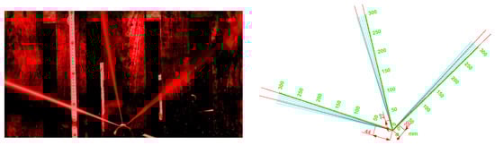
Figure 7.
Photo of the liquid plume (left) and contour of the geometry of the liquid plume (right) flowing out of the outlet port of the test head with diameters (from right) of 0.4, 0.6, and 0.8 mm at a discharge pressure of p = 20 MPa.

Figure 8.
Photo of the liquid plume (left) and contour of the geometry of the liquid plume (right) flowing out of the outlet port of the test head with diameters (from right) of 0.4, 0.6, and 0.8 mm at a discharge pressure of p = 30 MPa.

Figure 9.
Photo of the liquid plume (left) and contour of the geometry of the liquid plume (right) flowing out of the outlet port of the test head with diameters (from right) of 0.4, 0.6, and 0.8 mm at a discharge pressure of p = 40 MPa.
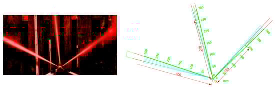
Figure 10.
Photo of the liquid plume (left) and contour of the geometry of the liquid plume (right) flowing out of the outlet port of the test head with diameters (from right) of 0.4, 0.6, and 0.8 mm at a discharge pressure of p = 50 MPa.
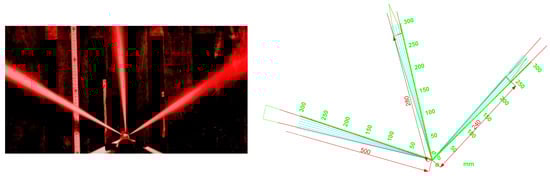
Figure 11.
Photo of the liquid plume (left) and contour of the geometry of the liquid plume (right) flowing out of the outlet port of the test head with diameters (from right) of 0.4, 0.6, and 0.8 mm at a discharge pressure of p = 60 MPa.
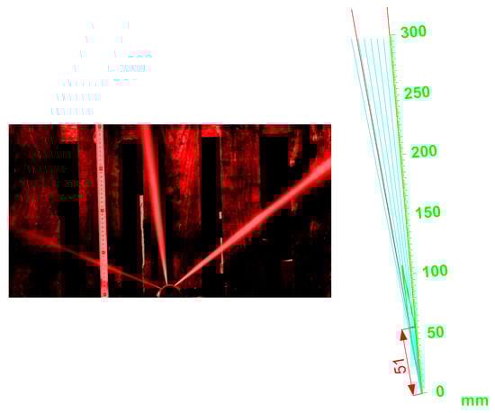
Figure 12.
Photo of the liquid plume (left) and contour of the geometry of the liquid plume (right) flowing out of the test head outlet port with a diameter of 1.0 mm at a discharge pressure of p = 10 MPa.

Figure 13.
Photo of the liquid plume (left) and contour of the geometry of the liquid plume (right) flowing out of the test head outlet port with a diameter of 1.0 mm at a discharge pressure of p = 20 MPa.

Figure 14.
Photo of the liquid plume (left) and contour of the geometry of the liquid plume (right) flowing out of the test head outlet port with a diameter of 1.0 mm at a discharge pressure of p = 30 MPa.

Figure 15.
Photo of the liquid plume (left) and contour of the geometry of the liquid plume (right) flowing out of the test head outlet port with a diameter of 1.0 mm at a discharge pressure of p = 40 MPa.
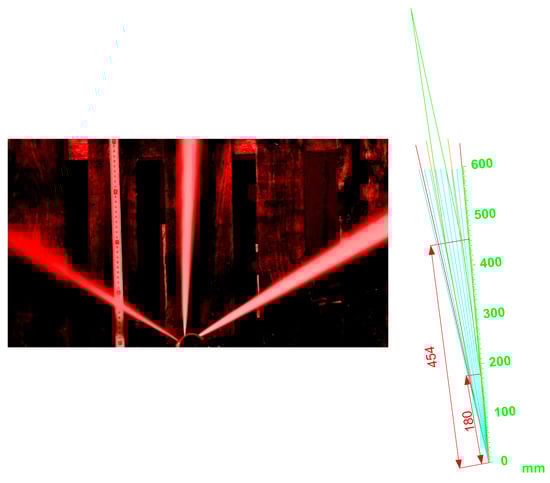
Figure 16.
Photo of the liquid plume (left) and contour of the geometry of the liquid plume (right) flowing out of the test head outlet port with a diameter of 1.0 mm at a discharge pressure of p = 50 MPa.
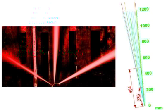
Figure 17.
Photo of the liquid plume (left) and contour of the geometry of the liquid plume (right) flowing out of the test head outlet port with a diameter of 1.0 mm at a discharge pressure of p = 60 MPa.
Table 1 provides a comprehensive overview of the liquid plume diameters emitted from the outlet holes of the designed rotary head during testing. The table includes data on the diameter of the outlet hole, the distance of the rotary head from the rock sample to be excavated, and the pressure of the working fluid. Figure 18 summarizes the information, showcasing the increase in the maximum distance of the jet’s effectiveness in relation to the liquid discharge pressure and the outlet hole diameters (0.4 mm, 0.6 mm, 0.8 mm, 1.0 mm). The variations in jet geometry, as depicted in Figure 17, are detailed in Table 2, taking a 1.0 mm diameter drill head outlet hole as an example, with the distance from the rock sample ranging from 10 to 60 MPa.

Table 1.
Angles of expansion of the liquid jet as a function of discharge pressure and diameter of the test head outlet holes.

Figure 18.
Comparison of the geometry of liquid streams at discharge pressure p = 10–60 MPa and depending on the diameter of the openings.
Table 2.
Fluid jet diameter as a function of distance from the test head for an outlet hole of d = 1.0 mm diameter and pressure p = 10–60 MPa.
The geometries obtained for the fluid stream flowing out of the holes will be utilized to determine the potential crater diameter when directed at rock from the mining holes of the static test head. However, the achieved plume diameters may not ensure effective crater formation if the contact occurs at a distance of 200 mm from the rock. The propagated hole diameter, measured at d = 27.20 mm, allows the cutting head to freely enter its interior during the drilling of a small-diameter radial hole.
As the depth of small-diameter holes increases during hydraulic radial drilling, pressure losses in the circulation system may result in decreased cutting quality and, consequently, a reduction in radial hole diameter. This effect can lead to blockage of the head feed. Therefore, a crucial consideration is the potential modification of the head and/or the drilling head design to increase the propagated radial hole diameter, directly influencing the depth of drilling small-diameter radial holes. These proposed modifications will be explored further in a forthcoming article currently in development.
6. Discussion
The proposed hydraulic radial drilling technology, developed as part of the research described in this article, offers the potential to increase the exploitation efficiency of active hydrocarbon boreholes. Additionally, it provides an opportunity to initiate the exploitation of boreholes intended for decommissioning or those with low deposit energy. The technology’s environmental impact is reduced, as it eliminates the need for drilling new boreholes, aligning with principles conducive to a low-carbon economy. This adaptation can be particularly beneficial for methane extraction from coal deposits. During the research and laboratory work, the concept of the hydraulic drilling head was thoroughly investigated. This article primarily focuses on determining the geometry of the stream flowing out of the cutterhead openings, as discussed in chapter 5. The technology described for using a hydraulic rotary nozzle has the potential for successful application in various industrial sectors. However, its implementation in other industries would require careful consideration of the technology’s requirements and its adaptation to meet specific application tasks. Existing solutions in the market typically involve drilling a base vertical hole with a normal diameter and a horizontal section. Subsequent branch holes are drilled from this base horizontal hole. On the other hand, various technologies concentrate on drilling multiple multilateral, multidiameter holes originating from the vertical section of the base hole. In contrast, other authors have outlined a method based on drilling a borehole with a vertical section followed by a horizontal borehole. This primary base borehole has departures in the direction of the layer being penetrated. The authors of the current article have introduced a different approach, suggesting the utilization of existing wells as a base. From these existing wells, multiple small-diameter (25–60 mm) wells would be drilled, diverging in different directions with varying lengths for each individual well [21].
7. Conclusions
The outlined technology concept holds the potential to revitalize old wells that have been decommissioned or possess low reservoir energy. The hydraulic drilling nozzle, harnessing the energy of fluid streams for extraction, stands as a pivotal component of the aforementioned technology, meticulously examined throughout a series of articles.
Key observations and conclusions drawn from numerous studies conducted during the design phase include:
- The implementation of a hydraulic drilling head necessitates the utilization of a sophisticated technology developed during the study period. The central component of this technology is a coiled tubing unit equipped with an array of devices and components. These are installed at the end of the drill window in the casing, facilitating the insertion of the designed drilling nozzle in the direction of the reservoir layer.
- The technological solution involves accessing and extracting methane from deposits located in coal seams. The process is initiated by drilling a borehole to expose methane deposits situated in coal formations. This is achieved by drilling a straight vertical borehole, accompanied by a horizontal section within the coal overburden layer. Subsequently, small-diameter openings are drilled into the coal seam by employing hydraulic drilling nozzles, as illustrated in Figure 1.
- The invented technology will contribute to the increased exploitation of hydrocarbon deposits, particularly in damaged near-wellbore zones or those requiring simple intensification methods. This enhancement is achieved by expanding the contact area of the main wellbore with the reservoir layer.
- The application of this technology in methane extraction from coal deposits promises safe degassing, coupled with economic benefits.
- The stream disperses in geometry after exiting the outlets, making it crucial to determine the maximum length of the stream that corresponds to the minimum hydraulic energy required for unimpeded drilling in the reservoir layer.
- The research conducted confirms the dependence of the jet length on pressure and allows for the identification of the minimum jet length based on the diameter of the outlet as a function of pressure. This information is crucial to determine the hydraulic energy required for the effective excavation of the rock layer and the safe entry of the nozzle into the geological formation being excavated.
- During the hydraulic drilling process, the nozzles must move freely through the hydraulically excavated formation into its interior during the drilling of a small-diameter radial hole. However, as the depth of the radial holes increases, pressure losses in the drilling fluid circulation system will cause a decrease in drilling quality. This, in turn, results in a reduction in the diameter of the radial hole, ultimately leading to a blockage of the head feed.
- Modifying the head and/or designing the drilling head to increase the diameter of the propagated radial hole will directly impact the depth of drilling small-diameter holes.
Author Contributions
Conceptualization, P.T., R.W., A.Z. and W.T.; methodology, P.T., A.Z., R.W. and W.T.; software, P.T.; validation, P.T. and R.W.; formal analysis, P.T.; investigation, P.T., A.Z. and W.T.; resources, P.T.; data curation, P.T.; writing—original draft preparation, P.T.; writing—review and editing, P.T.; visualization, P.T. and A.Z.; supervision, P.T. and R.W.; All authors have read and agreed to the published version of the manuscript.
Funding
This research received no external funding.
Data Availability Statement
Data are contained within the article.
Conflicts of Interest
The authors declare no conflict of interest.
References
- Gonet, A.; Nagy, S.; Rybicki, C.; Siemek, J.; Stryczek, S.; Wiśniowski, R. Technologia Wydobycia Metanu z Pokładów Węgla Kamiennego. Górnictwo I Geologia. AGH 2010, 5, 3. [Google Scholar]
- Baran, P.; Rogozińska, J.; Zarębska, K.; Porada, S. Analiza Układu Węgiel Kamienny—Gaz pod Kątem Intensyfikacji Wydobycia Metanu z Użyciem Ditlenku Węgla. Przemysł Chem. 2014, 93, 12. [Google Scholar]
- Artymiuk, J.; Kiełbik, W. Koncepcja Odmetanowania Pokładów Węgla Otworami Wiertniczymi w KWK Szczygłowice. Wiert. Naft. Gaz 2007, 24, 1. [Google Scholar]
- Dickinson Ben, W.O.; Dickinson, R.W. Horizontal Radial Drilling System. In Proceedings of the SPE California Regional Meeting, Bakersfield, CA, USA, 27–29 March 1985. [Google Scholar] [CrossRef]
- Dickinson Ben, W.O.; Dykstra, H.; Nees, J.M.; Dickinson, E. The Ultrashort Radius Radial System Applied to Thermal Recovery of Heavy Oil. In Proceedings of the SPE Western Regional Meeting, Bakersfield, CA, USA, 30 March–1 April 1992. [Google Scholar] [CrossRef]
- Tianyu, W.; Qingling, L.; Bin, Z.; Shouceng, T.; Gensheng, L.; Zhaoquan, G. Fracture Initiation Characteristics from Multiple Radial Wellbores. In Proceedings of the 54th US Rock Mechanics/Geomechanics Syposium, Physical Event Cancelled, Golden, CO, USA, 28 June–1 July 2020. [Google Scholar]
- Ibeh, S.; Obah, B.; Chibuze, S. Investigating the Application of Radial Drilling Technique for Improved Recovery in Mature Niger Delta Oil Fields. In Proceedings of the Nigeria Annual International Conference and Exhibition, Lagos, Nigeria, 31 July–2 August 2017. [Google Scholar]
- Wiśniowski, R.; Knez, D.; Hytroś, Ł. Drillability and Mechanical Specific Energy Analysis on The Example of Drilling in The Pomeranian Basin. AGH Drill. Oil Gas 2015, 32, 201. [Google Scholar] [CrossRef][Green Version]
- Buset, P.; Riiber, M.; Arne, E. Jet Drilling Tool: Cost-effective Lateral Drilling Technology for Enhanced Oil Recovery. Paper SPE 68504. Presented at the SPE/ICoTA Coiled Tubing Roundtable, Houston, TX, USA, 7–8 March 2001. [Google Scholar]
- Abdel-Ghany, M.A.; Siso, S.; Hassan, A.M. New Technology Application, Radial Drilling Petrobel, First Well in Egypt. Paper OMC-2011-163. Presented at the 10th Offshore Mediterranean Conference and Exhibition, Ravenna, Italy, 23–25 March 2011. [Google Scholar]
- Rychlicki, S. Możliwości Zwiększenia Efektywności Wydobycia Ropy Naftowej ze Złóż Karpackich; Wydawnictwa Naukowe AGH: Krakow, Poland, 2010; 184p. [Google Scholar]
- Wojnarowski, P.; Stopa, J.; Janiga, D.; Piotr, K. Możliwości, Zwiększenia, Wydobycia Ropy Naftowej w Polsce z Zastosowaniem Zaawansowanych Technologii, Polityka Energetyczna. Energy Policy J. 2015, 18, 4. [Google Scholar]
- Yan, C.; Ren, X.; Cheng, Y.; Deng, F.; Zhang, J.; Li, Q. An Experimental Study on the Hydraulic Fracturing of Radial Horizontal Wells. Geomech. Eng. 2019, 17, 535–541. [Google Scholar] [CrossRef]
- Koulidis, A.; Pelfrene, G.; Ahmed, S. Experimental investigation of the rock cutting process and derivation of the 3D spatial distribution of the formation strength using in-cutter sensing. J. Pet. Explor. Prod. Technol. 2023. [Google Scholar] [CrossRef]
- Chi, H.; Li, G.; Huang, Z.; Tian, S.; Song, X. Maximum drillable length of the radiala horizontal micro-hole drilled with multiple high pressure water jets. J. Nat. Gas Sci. Eng. 2015, 26, 1042–1049. [Google Scholar] [CrossRef]
- Cinelli, S.D.; Kamel, A.H. Novel Technique to Drill Horizontal Laterals Revitalizes Aging Field. In Proceedings of the SPE/IADC Drilling Conference, Amsterdam, The Netherlands, 5–7 March 2013. [Google Scholar] [CrossRef]
- Jeffryes, B.P. Schlumberger Oilfield Research, Novel Drilling Techniques, Chapter 9.5. In Advanced Drilling and Well Technology; SPE: Willis, TX, USA, 2009. [Google Scholar]
- Salem Ragab, A.M. Improving well Productivity in an Egyptian Oil Feld Using Radial Drilling Technique. J. Pet. Gas Eng. 2013, 4, 103–117. [Google Scholar] [CrossRef]
- Liu, Q.; Tian, S.; Li, G.; Shen, Z.; Huang, Z.; Sheng, M.; Zhang, Z. Experimental Study of Radial Drilling-Fracturing for Coalbed Methane. In Proceedings of the 51st U.S. Rock Mechanics/Geomechanics Symposium, San Francisco, CA, USA, 25–28 June 2017. ARMA-2017-0110. [Google Scholar]
- Wiśniowski, R.; Teper, W.; Zwierzyński, A.J.; Złotkowski, A.; Toczek, P. Sposób, Powierzchniowego Odmetanowania Formacji Geologicznej Zawierającej Złoże Węgla Kamiennego, Patent PL436375A1. 2020. Available online: https://worldwide.espacenet.com/patent/search/family/082021230/publication/PL436375A1?q=ap%3DPL436375%2A (accessed on 1 September 2023).
- Stayton, R.J. Method for Drilling with Improved Fluid Collection Pattern. U.S. Patent 0266517 A1, 30 November 2006. [Google Scholar]
- Poole, J.M. Forming Multiple Deviated Wellbore. U.S. Patent 0005762, 13 January 2011. [Google Scholar]
- Foundas, E.; Bresnehan, R.M. Recovery or storage Process, 2017. CA Patent 2749591, 18 April 2017. [Google Scholar]
- William, C.M. Drain Hole Drilling in a Fractured Reservoir. U.S. Patent 0030180 A1, 2 February 2017. [Google Scholar]
- Quingling, L.; Shouceng, T.; Gensheng, L.; Mao SKamy, S.; Haizu, W.; Ruyue, M.; Zhaoguan, G.; Lidong, G. Influence of Weakness Plane on Radial Drilling with Hydraulic Fracturing Initiation. In Proceedings of the 52nd U.S. Rock Mechanics/Geomechanics Symposium, Seattle, WA, USA, 17–20 June 2018. [Google Scholar]


Disclaimer/Publisher’s Note: The statements, opinions and data contained in all publications are solely those of the individual author(s) and contributor(s) and not of MDPI and/or the editor(s). MDPI and/or the editor(s) disclaim responsibility for any injury to people or property resulting from any ideas, methods, instructions or products referred to in the content. |
© 2023 by the authors. Licensee MDPI, Basel, Switzerland. This article is an open access article distributed under the terms and conditions of the Creative Commons Attribution (CC BY) license (https://creativecommons.org/licenses/by/4.0/).