Review

Areas of Fan Research—A Review of the Literature in Terms of Improving Operating Efficiency and Reducing Noise Emissions

by
Marian Piwowarski
1,* and
Damian Jakowski
2
1
Institute of Energy, Faculty of Mechanical Engineering and Ship Technology, Gdansk University of Technology, 80-233 Gdańsk, Poland
2
Institute of Ocean Engineering and Ship Technology, Faculty of Mechanical Engineering and Ship Technology, Gdansk University of Technology, 80-233 Gdańsk, Poland
*
Author to whom correspondence should be addressed.
Energies 2023, 16(3), 1042; https://doi.org/10.3390/en16031042
Submission received: 14 November 2022 / Revised: 4 January 2023 / Accepted: 14 January 2023 / Published: 17 January 2023
(This article belongs to the Section J2: Thermodynamics)

Abstract

:
Fans as industrial devices are among the most significant single recipients of driving energy. Therefore, they represent an important area of energy savings to reduce CO2 emissions. The ubiquity of fans and their operation under conditions different from the optimum provides an opportunity for more significant global reductions in the energy used to drive them. The second important aspect, besides energy efficiency, related to the operation of fans is the noise they generate. This article studies fans in various operating configurations, emphasizing improving operating efficiency and reducing noise emissions. The subject matter undertaken is based on the current trends and needs of the industry, notably the ventilation and power industry. The article attempts a detailed literature review taking into account just these aspects. The paper is divided into three main sections, with an analysis of the literature in the areas of energy efficiency, considering the operation of fans with the necessary instrumentation, the incidence of vibration, and noise optimization. The final area of analysis is the parameters and components of the plant in which the fans operate. This article identifies possible sites for further research and scientific work to improve and optimize the areas identified earlier.

1. Introduction

In recent years, the issue of optimizing the operation of devices in terms of energy efficiency has become particularly important. The legal status and the global situation have a considerable and recently even decisive influence on these activities. An example is the European Union’s climate regulation package, “Fit for 55”, aimed at reducing greenhouse gas emissions in Europe by no less than 55% by 2030 compared to 1990 levels and reducing overall energy consumption. In systems generating electricity, transmitting and converting it into a different type, a trend has emerged to improve machines’ efficiency and energy efficiency [1].
Works on fans’ construction have been carried out since around 1832, and the efficiency of fans has already reached a very high value [2]. It is essential, however, that the widespread occurrence of fans and their operation in far-from-optimal conditions gives a chance for a significant global reduction in energy consumption used to drive them.
Another aspect, apart from energy efficiency related to the operation of fans, is the noise they generate. The research indicates that the primary sources of noise are flow turbulence, variable forces arising on the blade surfaces as a result of breaking the vortices at the rear edges of the blade. Moreover, variable forces on the blade surfaces result from cutting the turbulent aerodynamic wake, inlet directing devices, and variable forces on the tongue and blades result from their cooperation [3].
The main goal of designers of centrifugal fans is to achieve the highest possible efficiency, while maintaining the lowest possible emitted acoustic power for the assumed efficiency and total pressure value.
J. Justus Partels is believed to be the inventor of mechanical room ventilation [4]. In 1711, he developed a fan to supply air to the enclosed spaces of the mine. The rapid development of rotating machines, including fans, occurred in 1754. This year, L. Euler, in his work entitled “A complete theory of machines operating under the influence of water” gave the fundamental equation of flow machines that he developed [5].
Fans are divided according to the way of installation, design features, pressure value, number of rotors, application, and place of installation. Due to the type of installation, the following are distinguished: forcing fans, suction fans, and mixed, i.e., forcing-suction fans. A very general group is general-purpose fans. You can find machines intended to be used only in specific locations, e.g., mine or marine fans. Fans are also used in transport. They are used for transporting chemically active materials, including gases, exhaust gases, and acids, and for pneumatic transport. We also distinguish explosion-proof and smoke exhaust fans. The former is used in rooms at risk of explosions, including chemical laboratories and laboratories.
On the other hand, smoke exhaust fans can be used where there may be a need to ventilate the air in which there are various fumes, including fire fumes. They can be installed in shopping malls, underground parking lots, or in office buildings [6]. They are also perfect as smoke exhaust devices in large kitchens, such as restaurants or canteens. Fans can also be divided according to the place of their installation into the roof, wall, and ceiling. Selected examples of the use of fans in technology [4,7]:
  • Ventilation devices (airing rooms), steel mills, power plants, mines, lecture halls, cinemas, foundries, etc.;
  • For cooling engines and generators;
  • For cooling internal combustion engines;
  • Fan cooling towers;
  • Air condensers in refrigeration and cooling systems;
  • As draft fans;
  • In electronic systems intended for cooling components.
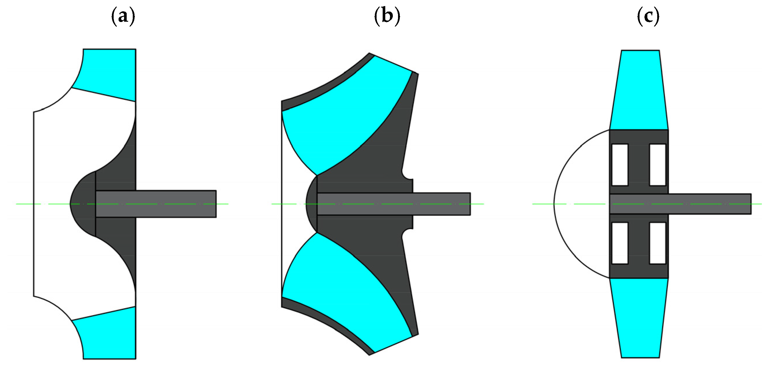
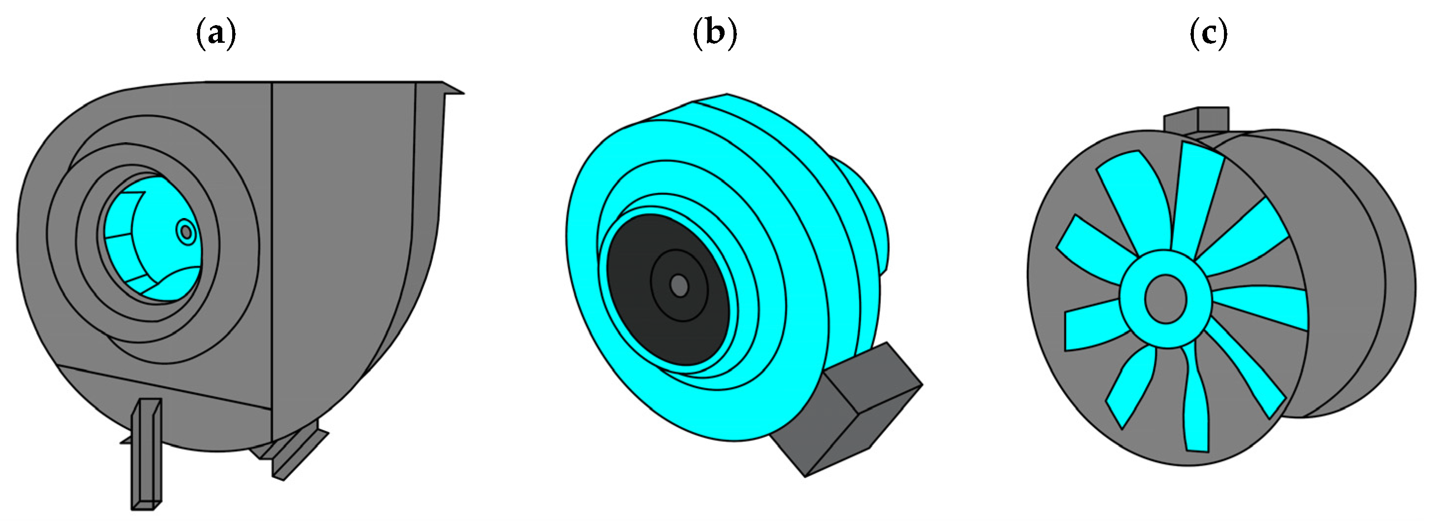
Companies producing ventilation devices are looking for new solutions to improve the comfort of use, reduce their energy consumption, and facilitate installation.
The main element of the fans is movable blade systems—rotors and diffusers. The rotor is the primary and essential part of any ventilation device. Through it, energy transfer occurs, the purpose of which is to overcome airflow resistance. The rotor should be designed to ensure the highest efficiency, resistance, and low noise level (more on this in the literature review later in the article). Figure 1 presents types of fan impellers [7].
It is possible to make three types of radial fan impeller blades with an angle β2 < 90° (Type I), β2 > 90° (Type II), or β2 = 90° (Type III), which results in the appropriate design of the blades (Figure 2). Type I paddles are characterized by a greater increase in static pressure than in dynamic pressure and ensure high efficiency and the good shape of the compressor stage characteristics. Type II blades provide very high kinetic energy. The conversion of kinetic energy to potential energy realized in diffusers is done with low efficiency. They are used where there is a need for high values of the flowing medium. Type III blades have good strength properties (peripheral speeds up to 600 m/s), and they guarantee significant enthalpy gains with small dimensions and light weights [7].
In centrifugal fans, where the medium flows out of the impeller at high speed, bladeless or blade diffusers are used, which partially convert this kinetic energy into static pressure. A bladeless diffuser (Figure 3) consists of two discs arranged parallel or conically. Usually, to avoid the impact and dispersion of the jet leaving the impeller, the width at the diffuser inlet is 1 mm to 2 mm greater than the width of the impeller [7]. On the other hand, the blade diffuser (Figure 4) consists of blades with a fixed or variable angle of setting, made of steel sheet or in the form of a cast together with the side wall [7].
In order to equalize the velocity and pressure in the impeller pattern, the blade diffuser should be moved away from the impeller outlet. This improves the conditions of cooperation between the rotor and the diffuser, thus increasing the efficiency and reducing the noise emitted by the machine [8].
In the HVAC industry (Heating, Ventilation, Air Conditioning) in addition to traditional designs, i.e., centrifugal fans (Figure 5a) and axial (Figure 5c), a broad group are duct fans with radial rotors (Figure 5b) [9].
Due to design considerations, individual fans’ areas of application and functional features are strictly defined. In work [9], traditional fans’ structures are compared with a group of radial and axial machines. The exact diameter was used as the criterion assembly of the pipeline to which the machine is dedicated. Centrifugal fans (built-in spiral) are characterized by the high-pressure increase (compression) with relatively low efficiency, smaller noise, and low vibration of the blades due to the high rigidity of the blade rim. On the other hand, axial fans have high efficiency, but small pressure gains. In this case, direct installation in the channel is possible without additional items. The achieved efficiency is an additional advantage of axial fans. Work analysis [10] suggests a great demand for fans with smaller diameters and compact designs but with high static pressure.
By analyzing the flow through the fan impellers, the following directions of gas flow can be distinguished [4]:
(a)
Axial;
(b)
Axial with meridional acceleration;
(c)
Semi-axial;
(d)
Half-radial;
(e)
Semi-radial centrifugal;
(f)
Semi-radial centripetal;
(g)
Axial-radial;
(h)
Peripheral;
(i)
Radial disc;
(j)
Transverse.
The blades of the rotors are constructed in such a way that they transmit energy to the gas during rotation by increasing the spin. The flow in an axial fan results from adding the relative velocity w1 to the circumferential velocity u1. Axial fans produce small pressure increases with relatively high efficiency.
Diagonal fans fill the gap between axial and radial fans. The flow from the impeller flows to the stator blades, maintaining the axial direction, or it is introduced into the volute casing, flowing out through the discharge port.
In radial fans, the energy to the gas is transferred in the radial flow direction.
Previously, the inflow to the fan and impeller was axial. In the impeller inlet chamber, it changes to radial.
In axial-radial fans, energy is transferred to the gas through a relatively long blade, which at the beginning acts as a typical axial blade, and the next part as a radial blade.
Due to the “steep” blades, dust deposition is not observed in axial-radial fans, thanks to which they are used, among others, in the pneumatic transport of light solids.
Peripheral fans produce high-pressure rises compared to their small jets. They generate motion in numerous channels radially lateral to the backing plate, located around the circumference of the hub, in which the fluid is repeatedly radially accelerated.
Disc fans consist of a package of, e.g., 20 discs spaced about 2 mm apart. Through the axial channel, air flows to each disc and, by friction against the surface of the rotating discs, flows outside the package to the volute casing.
Cross-flow fans use centripetal flow in combination with the centrifugal flow. The energy supplied to the shaft is transferred to the gas in the form of dynamic pressure, which is why these fans work with flow retarding channels (e.g., heating devices).
To choose the right fan, start by understanding the basic requirements of the operating system, operating conditions such as airflow, pressure, temperature, airflow properties, and system structure. Other factors and their variability also make fan selection very complicated. These include cost, performance, material type, service life, space constraints, maintenance, drive systems, temperature, and operating range.
For building or expanding a ventilation system, it is worth taking measures aimed at energy optimization. The fan selection is based on calculating the requirements of air pressure and flow in the system, then finding the right fan to meet these requirements. It is complicated to predict the gas flow resistance in the installation. This variability, coupled with the contaminants present and the predicted effects of the change in system resistance, forces the use of large capacity and pressure parameters—above the potentially nominal value.
The fan should always be considered as a whole system in conjunction with the installation and other elements, w which include [11]:
  • Intake (intake nozzles, intake boxes, vane diffusers, filters);
  • An appropriately selected fan (steering blades, impeller blades, diffusers bladeless, reversing channels, etc.);
  • Fan drive (gear, belt, direct) with regulation and control;
  • Appropriate fittings and partitions;
  • Exhaust (guide vanes, exhaust manifolds, silencers);
  • Heat exchangers.
Example of fan system components can be found in the publication [11].
An appropriate approach is necessary to discuss the aspects related to the economic operation and maintenance of a (ventilation) installation. This is about analyzing the needs of individual elements and looking at the installation as a whole. The “Approach system” analyzes the inlet to the system and the outlet and the relationships between them. A systems’ approach usually includes the following elements/types of related activities:
  • Determining the current parameters and conditions of work;
  • Determining the current state and determining the future state of process production;
  • Operational data collection and analysis and workload cycle development;
  • Assessment of alternative system implementations and optimization areas,
  • Identification of the most economically and technically advantageous variants (necessarily taking into account all subsystems);
  • Implementing the best installation option;
  • An assessment of energy consumption in relation to working conditions;
  • Constant observation and ongoing optimization of the system;
  • Operation of the installation aimed at achieving maximum efficiency.
Ensuring the reliability of the fan operation often causes designers to design fan systems that are not contemporary and tend to compensate for uncertainties in the design process, increasing their pressure and efficiency (oversizing). Unluckily, oversizing fan systems creates troubles that can increase system operating costs while reducing fan reliability. Oversized fans do not operate at optimal operating points due to service requirements. In extreme cases, they can work unstably, generating excessive energy flows, which puts a load on the fan and the system, and thus much noise. As a result, oversized fans do not just cost more money, but they are also more expensive to operate. From the review of existing fan solutions and of conducted research on fans, three fundamental trends can be distinguished in the process of improvement of gas transport with the use of flow fans:
  • Improvement of the energy efficiency of the fan itself as a device, including the drive;
  • Conducting a series of noise reduction treatments;
  • Improving the efficiency of gas transport in the installation.
It should be emphasized, however, that all three treatments are interrelated and interact directly with each other. The largest reserves are in the solution of the installation and selection of the fan for the installation, and then in the fan, its drive system and the method of parameter adjustment. Problems and costs related to wrong fan selection can be neutralized in the future by appropriate data collection as operational feedback. This data can help designers and operators improve the ventilation system’s efficiency [12].
The article is a review of research conducted in the field of ventilation and fans themselves. The authors searched the databases of Elsevier journals, trade journals, and databases of scientific conference articles (e.g., Internoise) from the last several years by searching using the keywords “fan efficiency” and “noise emissions of fans and installations,” among others. The bibliographic analysis that was carried out allowed a comprehensive collection of information related to engineering and research activities that improve energy efficiency and reduce fan noise. Other important aspects evaluated in the work were parameters and areas that can be optimized in the installation. Through the analysis, it is easier to identify areas for further research. Improving the energy efficiency of fans and selecting appropriate operating parameters is an area that research centers and universities should work on.

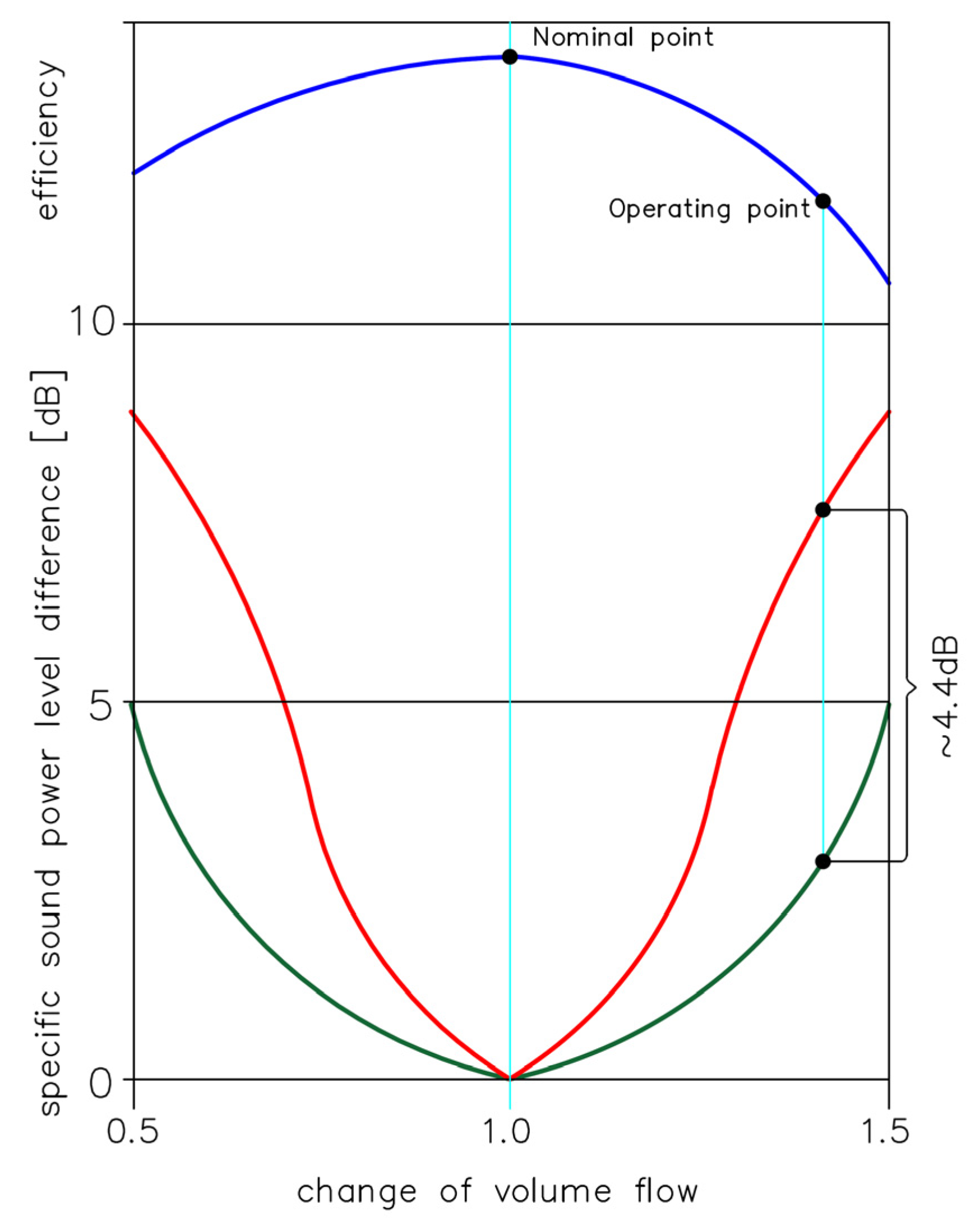
2. Energy Efficiency—Fan Operation

As mentioned in the introduction, one of the areas of scientific research is improving the energy efficiency of fans. Fans are among the most significant single energy consumers and therefore represent an essential energy-saving area to reduce CO2 emissions. The literature review shows that a large part of the generated electricity is consumed by electric motors, of which about 15% is consumed by receivers driving fans. In the USA, fans operating in the industrial sector consume about 11% of the electricity of all industrial motor drives [13,14]. In Sweden, fans consume about 8% and in Great Britain, more than 9% of the energy is produced [15]. Figure 6 shows an overview of where energy losses occur in the fan. We can observe aerodynamic and mechanical losses in the flow system (and outside it), power transmission, and control [16].
In order to overcome the losses, the fan generates an appropriate increase in the pressure of the total medium thanks to the mechanical energy supplied to the fan from the drive motor. Electric motors are used almost exclusively to accomplish this task.
This part of the energy transferred from the engine to the gas to realize its flow through the installation is called useful power, as opposed to the power lost in the drive and flow system of the fan.
The exact value of the useful power is calculated from the product of efficiency and total accumulation, and the correction factor ƒ was taken into account for accumulations exceeding 3.6 kPa.
N u = V ˙ s Δ p c ƒ
The drive unit supplies Power Ni to the fan’s flow system.
In the flow system, there are power losses caused by the friction of the medium against the walls of the flow channels, as well as the mutual friction of gas molecules against each other in the areas of vortices for both the impeller and the housing. This loss is called flow power loss and means Np.
In the flow system, a third power loss is distinguished, caused by the friction of the rotating outer walls of the rotor against the gas in the housing. The power loss due to the friction of the rotor discs is called the wading loss and is denoted by Nb. The carrier disc has a significant impact on the amount of wading losses.
On the other hand, Nv as power loss consists of the pressure drop in the impeller inlet chamber multiplied by the leakage flux.
All these three types of losses and the useful power added together are equal to the fan’s internal power [4]
N u + N p + N v + N b = N i
There are energy losses in the rotor and housing due to acceleration, deceleration, change of direction, friction, detachment of streams from the walls, and mixing of streams.
In the rotor, the following types of losses are distinguished:
-
Inlet on the funnel;
-
Change of flow direction from axial to radial;
-
Non-tangential flow to the rim;
-
Friction in the interscapular canal.
There are losses in the fan case:
-
Diffusivity of the case;
-
Sudden expansion of the flow;
-
Stream mixing;
-
Friction.
In the Sankey diagram, power flows from the left side to the right. Each component rejects a portion of the input energy due to inefficiencies in the following steps. The energy efficiency of each component is the ratio of the output power to the input power.
The mechanical energy on the fan shaft is used to generate power to the air stream at the outlet. Some input energy is lost due to aerodynamic losses, mechanical losses, and acoustic losses. The ratio of air power to fan shaft power defines the total efficiency of the fan.
Increasing the operational efficiency of rotating machines, including fans, should be a priority goal of international organizations influencing the creation of new market standards. According to the study presented by the International Energy Agency, it can be concluded that the total energy efficiency of rotating machines is a key item determining the possibilities of reducing energy consumption on a global scale [17]. An important parameter linked to the fan’s energy efficiency is the rotational speed, usually measured in revolutions per minute (rpm). The rotational speed has a significant impact on the performance characteristics of the fan. Efficiency changes in proportion to the change in rotational speed, pressure is the square of the change, and power demand is the third power. The rotational speed should be considered together with other problems, such as ambient noise, air temperature, fan load variation, and the mechanical strength of the fan. For example, centrifugal fans with forward curved blades require a relatively accurate estimate of the airflow in the installation and pressure requirements, as the wrong speed can result in a reduced capacity or excessive air flow and pressure variations.
The air stream’s temperature has a significant influence. For high temperatures, all materials show lower strength. Since the forces acting on blades, shafts, and bearings are proportional to the square of the rotational speed, high temperatures in the fans result in a low rotational speed. To a large extent, it is the temperature range that determines the type of fan and the selection of the appropriate material. Many materials lose their mechanical strength in high-temperature installations. The stresses increase with increasing fan speed; therefore, the lowest rotational speed is required for systems with high temperatures. Centrifugal fans are built for lower temperatures of the medium.
Table 1 shows the various analyses described in the literature, actions taken, and design measures increasing the efficiency of fans.
Today’s fans are subject to legal requirements regarding energy efficiency. It is important that they consume as little energy as possible, and this goal is subject to global, EU, and national requirements. In the above studies, the authors use various methods and focus on selected fan elements to optimize the flow, correcting the turbulence that arises. This, in turn, allows for changes to the seals, improvement of clearances, and modifications in the construction of the fans. Selected works also dealt with issues related to using artificial intelligence to improve work efficiency (not only fans but also entire ventilation systems).

3. Vibrations and Noise

In industrial ventilation processes, vibrations and generated noise can be a serious problem. The noise sources are vibrations of the fan impeller, body, piping, foundation, drive motor, and many other elements. High acoustic level causes fatigue in employees. In installations where fans operate, noise is produced by mechanical, electromagnetic, and aerodynamic phenomena [28].
The noise generated by the fan depends on the type of fan, air flow speed, and pressure. The increased noise level of a given type of fan is often the result of inefficient fan operation. The sources of vibrations and noise in the fan itself are, among others:
  • Design, thermal imbalance (heating unevenness, flow unevenness), operational imbalance (deposition of particles of the working medium, rotor erosion);
  • Bending, e.g., due to high permanent forces and material deflection;
  • Lost elements, e.g., a spatula;
  • Rubbing against body elements as a result of high vibrations, permanent bending of the rotor or axial displacement of the rotor as a whole;
  • Blade resonance leads to resonant vibrations and, consequently, fatigue of the material.
The motors produce considerable noise during operation. However, fan impellers are louder, and the difference between fan and motor sound levels often exceeds 6 dB, so they are inaudible. There are tables [4] presenting the noise level of motors of different sizes for different rotational speeds.
Non-stationary gas flow from the nozzle is a typical monopole sound source. The sound power of such a source is proportional to the fourth power of the gas velocity c4 and its density ρ, the square of the geometric dimension of the stream l2, and is inversely proportional to the speed of sound ad [4].
N ~ ρ   c 4 a d   l 2
Based on the dimensional analysis, the sound intensity can be represented by a formula [4]:
I = ρ c 3 = ρ 2 c 4 ρ c = p 2 ¯ ρ c
where p ¯ is the effective sound pressure value RMS (Roor Meane Square).
Real noise, modeled by an acoustic dipole, is produced by stationary and non-stationary forces existing in the source. In the case of fans, the forces are generated when the impeller blades and some casing elements flow around the gas stream with any time-dependent velocity distribution or with a time-independent (stationary) profile.
In the balance of energy losses of the fan, the acoustic power may be omitted. However, the noise associated with the spread of this type of energy is very annoying.
The air particles in contact with the fan surfaces are introduced into vibrations, which, due to the elasticity of the medium, are transmitted to the neighboring particles. The energy transferred to create the vibrating motion of the surrounding particles is the radiated energy.
The sound power radiated to the space around the fan depends in a first approximation on the power of the motor driving the fan, which in turn depends on the efficiency and pressure rise. The sound power level can be calculated with a high approximation from the formula [4]:
L N [ dB ] = 70 + 10 l g N s   ( k W ) + 10 l g Δ p c
where: N s electric   motor   rated   power ,   Δ p c fan s   damming   [ Pa ] .
The vibration of fans can also generate noise. The mechanical vibrations of the fan or its components arise as a result of:
-
Unbalance of rotating masses;
-
Non-axial engagement of clutch parts;
-
Work near resonance;
-
Aerodynamic flow disturbance;
-
Damage to bearings and incorrect clearances;
-
Electromagnetic interference affecting the engine;
-
Interference from external vibrations.
Since the fan can operate at any point of its characteristic depending on the installation resistance, the actual operating point in the installation is defined as the operating point. The specific sound power level varies with the flow rate. The lowest noise generation of the fan roughly corresponds to the optimal performance. Particular deviations of the volumetric flow—according to Figure 7—show the effect of the shift of the operating point on the level of generated noise [29]. For example, an increase in volume flow of about 40% from the nominal value results in an increase in the specific sound power level of more than 4 dB.
If a high fan noise level cannot be avoided, measures to reduce the acoustic energy must be used. To reduce noise, engineers use various methods, e.g., duct insulation, rubber or a suitable spring insulator or mounting the fan on a soft base. Another way is to install a sound-absorbing damping material or baffles to absorb vibrations. Active noise control methods are also a very important area of noise reduction.
Table 2 presents the collected literature on the methods of reducing noise generated by fans.
The main source of sound in a ventilation system is the fan. The problem of noise, or rather the noise produced by the fan, is very important, as confirmed by the number of scientific papers indicated above. The noise generated by the operation of the fan can be looked at from an energy point of view—it is closely linked to the efficiency and losses occurring in the system, and from an “aesthetic” point of view—it is not pleasant and affects people who are not far away. The noise generated by the fan depends on many factors. The main one is the design of the fan itself, in which attention should be paid to the number of blades and their shape. The next factors are efficiency and pressure, airspeed, the size and shape of the housing and its rigidity. We can separate noise into noise caused by aerodynamic and mechanical factors. Aerodynamic noise is directly related to the flow of air through the blade system and the accompanying changes in pressure distribution over the blade surface. Sources of mechanical noise are influenced by rotor imbalance, the incorrect operation of bearings, operation of the electric motor, and possible mechanical vibration of the components due to inadequate, that is, insufficient rigidity of the structure. In the literature summary above, the authors presented the results of work optimizing precisely those areas that are crucially related to noise emissions.

4. Parameters and Areas of Optimization of Plant Components

Taking a closer look at the system shown in Figure 6, one can make a more detailed analysis of the work factors and individual elements of the entire ventilation system.
AC motors in particular drive most industrial fans. They are mainly induction motors powered by a three-phase current 240 V or 480 V. Due to the expected voltage drops in the installation, power supplies are usually selected for higher voltages than motors. Slip, defined as the difference between the speed of the magnetic field and the speed of the motor shaft, is related to torque. This is a critical property of induction motors. The operating speeds of many fans are about 2% lower than their nominal speeds.
The fans spin at a slightly higher speed when the motors run with less slip. In systems that can effectively use this increased expense, it is a profit; but if the additional capacities are not useful, they generate additional energy consumption and increase operating costs. There are four main types of belts: flat belts, V-belts, cogged V-belts, synchronous belts, and mesh contact belt. Flat belts have a constant cross section and transmit power by frictional contact with the flat face of the pulley. Due to the function of the wedge as a force-transmitting element, V-belts are an improvement over a flat belt. Visualizations of types of fan belts with cross sections can be found in the publication [11]. V-belts have the same advantages as cogged V-belts. However, the use of smaller pulleys is only possible with cogged V-belts, thanks to the ribbed design (improving flexibility).
Compared to standard flat and V-belts, synchronous belts have many advantages. Due to the lack of slip losses, the use of synchronous belts turns out to be the most efficient type of drive. Due to the points that interlock with the grooves, synchronous belts can carry greater forces than conventional belts. This is possible by reducing the radial loads on the motor and fan bearings. Nevertheless, synchronous belts, despite their advantages, should be used with caution, as they are very loud. Synchronous belts are responsible for the key-torque transmission, which in installations with rapid load changes may increase the risk of failure and wear of driven machines.
In addition, they also require precise assembly, which is sometimes difficult to achieve in some ventilation systems. Depending on the design, construction, and gear ratio, the gearboxes have a wide range of efficiencies. Besides ensuring high reliability, it is a very important feature in installations with limited access to the drive system. It is worth noting that belt systems allow for great flexibility in changing the fan speed during operation [11].
The controller is another key element of the entire ventilation system—a mechanism that receives signals from the circuit. It is responsible for switching the engine power on and off. The high inrush currents associated with most AC motors cause power-quality problems in conventional systems, mainly generating voltage drops [11].
A properly selected control system allows for a gradual increase in voltage, reducing the inrush current. Operation at different rotational speeds is a common feature of motors used in fan systems. There are two ways to construct motors with different speeds. First, as one set with a switch, it allows you to power or discharge an additional set of poles. The second uses multiple windings, each feeding a different number of poles.
The first type of engine usually allows two operating speeds. Depending on the application, the second type of motor can have two, three, or four speeds. Multiple speeds make motors more expensive and less efficient than single-speed motors. For many fan applications, the flow control and advantages of different motor speeds make them attractive.
During operation, the fan rarely works at and around the nominal point. This results, among others, from the change of initial parameters, variable properties of the compressed gas or the wear of the machine.
In order to ensure the proper operation of the installation in which the fan operates, it is necessary to ensure proper pressure and proper efficiency. Therefore, there are two main tasks that the regulation should fulfill:
  • Maintaining constant final pressure with variable flow;
  • Maintaining constant performance with changing network characteristics.
Maintaining the proper pressure and appropriate efficiency of the gas supplied to the receiver is carried out in many ways [4]:
  • By changing the rotational speed of the rotor;
  • By changing the angles of the impeller blades;
  • By changing the angles of the guide vanes (at the inlet or outlet of the rotor);
  • By choking the medium on the suction side;
  • By choking the medium on the discharge side;
  • By blowing gas into the atmosphere or recirculating excess gas to the suction port.
The ducts used on one or both sides of the fan have a key impact on its performance. Through them, the forced air is directed (through pipes or ducts). Pipes are used in high-pressure systems. Channels made of sheet metal are used in low-pressure installations. A significant part of the total fan load is usually the friction between the air stream and the duct surface. Larger channels tend to have lower airflow resistance than smaller channels. Initial costs related to materials and installation are definitely higher for larger ducts [7]. However, the reduced energy cost due to lower friction offsets some of these costs and should be considered when retrofitting installations or during the initial design process.
Another important element of the entire installation are devices designed to control the flow—chests, inlet manifolds and impeller inlet ducts, which are responsible for supplying the medium in an appropriate way. The generated velocity and pressure distributions affect the operation of the rotor. Knowledge of the speed distributions allows for the proper design of the rotor-blade system. Two typical examples of axial fan inlet boxes are shown in Figure 8.
Thanks to this knowledge, it is also possible to apply design solutions that enable the dispersion and calming of vortices occurring, for example, at the inlet to the fan. A few examples can be found in the publication [11]. Vortices created by turbulent airflow cause noise when entering the fan inlet, especially in contact with the blades [11].
Pre-rotating can be caused by placing the fan close to the elbow. In order to improve the inflow conditions, it is possible to correct the spin by using turning vanes.
A similar situation may occur when placing a bend too close to a fan inlet which can impair fan performance. It is recommended that the length of the straightening channel is three times longer than the supply channel. The visualization can be found in the publication [11].
In ventilation installations, fan performance may be degraded by placing the fan inlet too close to the tee. In such cases, a splitter plate is recommended if space constraints force a close gap.
There are many losses in the fan stage, which reduce the efficiency of the equipment. Losses are generally divided into:
  • Internal losses—changing to heat transferred to the flowing factor inside the body. They occur in the impeller blade channel and diffuser. Their value depends on the friction against the walls and intermolecular friction, but also on changes in the flow direction and the channel cross section. Vortices, flows at the walls of the channels, or impacts against the walls, e.g., at the inlet, also have an influence;
  • External losses—occurring outside the body do not affect the thermal state of the flowing medium; however, they significantly affect the power supplied to the machine. They appear in, for example, interstage seals. External losses are also mechanical losses.
Leaks occur in most flow systems and installations. System leakage can be significant, so the associated operating costs should be considered when designing the installation and selecting the fan. Already at the stage of designing and preparing the documentation, variables such as the type of channel, tightness, and quality of connectors, joining technique and whether all the requirements for sealing the channel system are met. Failure to take leakage prevention into account may result in inadequate system performance. System leaks tend to increase over time. The seals dry out and lose their properties, and the connections in the installation are loosened by vibration. The leakage of the system is also largely dependent on the pressure in the duct. Excessive pressure build-up can be the consequence of installing an oversized fan, which increases airflow and leakage losses. Assuming the installation characteristics do not change due to leakage, the flow increases by 5%, which requires a 5% increase in fan speed and a 16% increase in power.
This point indicates the impact of individual parameters on the operation of the entire installation, and Table 3 shows the measures to improve the functioning of the installation described in the bibliography.
The review of the bibliography showed several studies conducted in recent years by research centers and scientific institutions aimed at improving efficiency and reducing noise in the generally understood fan-around installation. These works were mainly related to the modernization of fan control systems, modification of the flow channels (reduction of turbulence, minimization of friction, and therefore flow losses), optimization of clearances, valves, dampers, and many other procedures. All modifications, indicated in Table 3, relate to improving efficiency and minimizing vibrations and generating noise in the installation.

5. Conclusions

The article is a review of the literature touching on aspects of fan operation. The main focus is on issues related to the study of fans in various operating configurations, with particular emphasis on improving operating efficiency and reducing noise emissions. The selected topics are related to the current research conducted by the authors as well as based on the ground of current trends and needs of the industry, especially the ventilation and power industry. Fans and their installations are one of key industrial installations. This applies not only to the noise generated but especially to electricity consumption. It is estimated that electric motors consume about 50% of the electricity generated. The motors driving the fans consume as much as 10% of this value [13]. To date, the activities of fan-manufacturing companies have treated energy issues with neglect, and ventilation systems are often designed conservatively and with a tendency to compensate for uncertainties in the design by increasing their capacity and pressures. Increasing system operating costs (with a simultaneous decrease in fan reliability) can be caused by oversizing the fan installation. This also translates into an unstable operation. Oversizing, unstable operating points generate an additional problem in the form of increased and disruptive noise emissions [6]. That is why the analysis presented here indicates the areas of ongoing research and their results. However, it should be noted that these systems should be treated comprehensively, i.e., not only analyzing the needs of individual elements but also looking at the installation as a whole since these elements interact with each other and entail certain effects. The biggest reserves lie in the installation’s solution and the fan’s selection for the installation, and then in the fan itself, its drive system, and the way the parameters are regulated. Problems and costs associated with poor fan selection can be eliminated in the future by proper data collection as feedback from the operation. This data can help designers and operators improve the ventilation system’s performance [4]. The authors are also researching to develop a neural model that creates characteristics of fans operating under real conditions based on a limited number of inputs. The goal is a model that allows fans to be optimized for maximum efficiency and minimum noise emissions from the unit’s operation under real operating conditions.

Author Contributions

Conceptualization, M.P. and D.J.; methodology, M.P. and D.J.; writing—original draft preparation, M.P. and D.J.; writing—review and editing, M.P. and D.J.; visualization, M.P. and D.J.; supervision, M.P. and D.J. All authors have read and agreed to the published version of the manuscript.

Funding

This research received no external funding.

Institutional Review Board Statement

Not applicable.

Informed Consent Statement

Not applicable.

Data Availability Statement

Not applicable.

Conflicts of Interest

The authors declare no conflict of interest.

References

  1. 2021 Commission Work Programme—From Strategy to Delivery. Available online: https://ec.europa.eu/commission/presscorner/detail/en/ip_20_1940 (accessed on 25 October 2022).
  2. Romik, D.; Czajka, I.; Gołaś, A. Numerical Study of the Effect of Selected Design Parameters on the Aerodynamic Noise of a Radial Fan; Institute of Rock Mechanics Polish Academy of Sciences: Kraków, Poland, 2016; Volume 18, pp. 43–52. (In Polish) [Google Scholar]
  3. Engel, Z. Environmental Protection against Vibrations and Noise; Polish Scientific Publishers: Warszawa, Poland, 2001; ISBN 83-01-13537-9. (In Polish) [Google Scholar]
  4. Fortuna, S. Fans. Theoretical Basis, Structural and Operational Issues and Application; Techwent Publishing House: Kraków, Poland, 1999; ISBN 83-912363-0-7. (In Polish) [Google Scholar]
  5. Majcher, M. Numerical Analysis of Three-Dimensional Flows in Key Components of Axial Fans. Ph.D. Thesis, Military University of Technology, Warsaw, Poland, 2021. (In Polish). [Google Scholar]
  6. Piwowarski, M.; Ziemiański, P.; Czyżewicz, J.; Bortkiewicz, M.; Laszuk, K.; Galara, I.; Pawłowska, M.; Cybulski, K. Autonomous remote measurement system for industrial fans as a result of an innovative project stage. Instal 2022, 3, 14–21. (In Polish) [Google Scholar] [CrossRef]
  7. Piwowarski, M. Flow Compressors; Foundation for the Promotion of the Shipbuilding Industry and the Maritime Economy: Gdańsk, Poland, 2017. (In Polish) [Google Scholar]
  8. Pałucki, Z. Analysis of Real Gas Flow through the Adjustable Vane Diffuser of a Radial Compression Machine. Ph.D. Thesis, Poznan University of Technology, Poznań, Poland, 2014. (In Polish). [Google Scholar]
  9. Siwek, T. Studies of Flows in an Axially Mounted Radial Impeller Fan. Ph.D. Thesis, Academy of Mining and Technology, Gdańsk, Poland, 2018. (In Polish). [Google Scholar]
  10. Wettergren, O. In-line Fans: Considerations for Sizing & Selection. Heat. Pip. Air Cond. Eng. 2007, 79, 22–25. [Google Scholar]
  11. U.S. Department of Energy. Improving Fan System Performance—A Sourcebook for Industry; National Renewable Energy Lab.: Golden, CO, USA, 2003. [Google Scholar]
  12. Czyżewicz, J.; Jaskólski, P.; Ziemiański, P.; Piwowarski, M.; Bortkiewicz, M.; Laszuk, K.; Galara, I.; Pawłowska, M.; Cybulski, K. Towards Designing an Innovative Industrial Fan: Developing Regression and Neural Models Based on Remote Mass Measurements. Energies 2022, 15, 2425. [Google Scholar] [CrossRef]
  13. Sathaye, N.; Phadke, A.; Shah, N.; Letschert, V. Potential Global Benefits of Improved Ceiling Fan Energy Efficiency; Tom LBNL Report; Ernest Orlando Lawrence Berkeley National Laboratory: Berkeley, CA, USA, 2013. [Google Scholar]
  14. Yu, J.; Zhang, T.; Qian, J. Electrical Motor Products International Energy-Efficiency Standards and Testing Methods; Woodhead Publishing Limited: Cambridge, UK, 2011. [Google Scholar]
  15. Schild, P.G.; Mysen, M. Recommendations on Specific Fan Power and Fan System Efficiency; AIVC document AIC-TN65; INIVE EEIG: Oslo, Norway, 2009; ISBN 2-930471-30-1. [Google Scholar]
  16. Trane, Engineers Newsletter, Volume 43-3. 2014. Available online: https://www.trane.com/content/dam/Trane/Commercial/global/products-systems/education-training/engineers-newsletters/standards-codes/ADMAPN052-EN_100114_final.pdf (accessed on 24 October 2022).
  17. Waide, P.; Brunner, C. Energy-Efficiency Policy Opportunities for Electric Motor-Driven Systems; International Energy Agency: Paris, France, 2011. [Google Scholar]
  18. Jung, J.H.; Joo, W.G. Effect of tip clearance, winglets, and shroud height on the tip leakage in axial flow fans. Int. J. Refrig. 2018, 93, 195–204. [Google Scholar] [CrossRef]
  19. Gholamian, M.; Rao, G.K.M.; Panitapu, B. Effect of axial gap between inlet nozzle and impeller on efficiency and flow pattern in centrifugal fans, numerical and experimental analysis. Case Stud. Therm. Eng. 2013, 1, 26–37. [Google Scholar] [CrossRef] [Green Version]
  20. Azem, A.; Mathis, P.; Stute, F.; Hoffmann, M.; Müller, D.; Hetzel, G. Efficiency increase of free running centrifugal fans through a pressure regain unit used in an air handling unit. Energy Build. 2018, 165, 321–327. [Google Scholar] [CrossRef]
  21. Hati, A.S. A comprehensive review of energy-efficiency of ventilation system using Artificial Intelligence. Renew. Sustain. Energy Rev. 2021, 146, 111153. [Google Scholar]
  22. De Souza, E. Improving the energy efficiency of mine fan assemblages. Appl. Therm. Eng. 2015, 90, 1092–1097. [Google Scholar] [CrossRef]
  23. Lin, Y.; Fan, T.; Zheng, X. Roles of recirculating bubble on the performance of centrifugal compressors. Aerosp. Sci. Technol. 2021, 118, 107073. [Google Scholar] [CrossRef]
  24. Eszter, L.; Janos, V. Flow topology and loss analysis of a square-to-square sudden expansion. J. Build. Eng. 2021, 41, 102802. [Google Scholar]
  25. Parpanchi, S.M.; Farsad, S.; Ardekani, M.A.; Farhani, F. Experimental investigation of a diffuser for use in skydiving vertical wind tunnel. Exp. Therm. Fluid Sci. 2021, 125, 110393. [Google Scholar] [CrossRef]
  26. Ch, S.V.; Anantharaman, K.; Rajasekaran, G. Effect of blade number on the performance of centrifugal fan. Mater. Today Proc. 2022, 72, 1143–1152. [Google Scholar] [CrossRef]
  27. Hargreaves, J.A. Analysis and Control of Acoustic Modes in Cylindrical Cavities with application to Direct Field Acoustic Noise (DFAN) Testing. In Proceedings of the Internoise 2022, Glasgow, UK, 21–24 August 2022. [Google Scholar]
  28. Sorgüvena, E.; Doğan, Y. Acoustic optimization for centrifugal fans. Noise Control Eng. J. 2012, 60, 379–391. [Google Scholar] [CrossRef]
  29. Reitz—Handbook Radial Fans. 2012. Available online: https://www.reitzgroup.com/en/downloads.html (accessed on 26 October 2022).
  30. Jung, J.H.; Joo, W.G. Analysis on hub vortex and the improvement of hub shape for noise reduction in an axial flow fan. In Proceedings of the Internoise 2019, Madrid, Spain, 16–19 June 2019. [Google Scholar]
  31. Sunghyun, M.; Namuk, C. An Aeroacoustic Comparison of Centrifugal Fans with Backward-curved and Airfoil Blades. In Proceedings of the Internoise 2019, Madrid, Spain, 16–19 June 2019. [Google Scholar]
  32. Chen, W.; Kai, M. Aerodynamic and Acoustic Optimization of a Multi Blade Centrifugal Fan. In Proceedings of the Internoise 2019, Madrid, Spain, 16–19 June 2019. [Google Scholar]
  33. Czwielong, F.; Krömer, F.; Becker, S. Sound Emissions of Axial Fans with Leading-Edge Serrations on different spanwise Locations. In Proceedings of the Internoise 2019, Madrid, Spain, 16–19 June 2019. [Google Scholar]
  34. Hurtado, M.; Burdisso, R. Axial Fan Design Using Multi-Element Airfoils to Minimize Noise. In Proceedings of the Internoise 2019, Madrid, Spain, 16–19 June 2019. [Google Scholar]
  35. Kuranaga, T.; Minorikawa, G.; Nakano, T. Experimental Study on Noise Characteristics and Evaluation of Small Ducted Fan. In Proceedings of the Internoise 2018, Chicago, IL, USA, 26–129 August 2018. [Google Scholar]
  36. Krömer, F.J.; Moreau, S.; Becker, S. Experimental investigation of the interplay between the sound field and the flow field in skewed low-pressure axial fans. J. Sound Vib. 2019, 442, 220–236. [Google Scholar] [CrossRef]
  37. Tong, F.; Qiao, W.; Xu, K.; Wang, L.; Chen, W.; Wang, X. On the study of wavy leading-edge vanes to achieve low fan interaction noise. J. Sound Vib. 2018, 419, 200–226. [Google Scholar] [CrossRef]
  38. Chen, H.; Qin, Y.; Wang, R. The optimization and flow diagnoses for a transonic fan with stage flow condition. Aerosp. Sci. Technol. 2018, 80, 247–260. [Google Scholar] [CrossRef]
  39. Badkar, P.S.; Benal, M.M. Noise reduction in power looms using nitrile rubber polymer. Mater. Today Proc. 2022, 66, 1779–1783. [Google Scholar] [CrossRef]
  40. Dhamande, L.S.; Bhaurkar, V.S.; Pankaj, N.P. Vibration analysis of induced draught fan: A case study. Mater. Today Proc. 2022, 72, 6657–6663. [Google Scholar] [CrossRef]
  41. Ottersten, M.; Yao, H.D.; Davidson, L. Inlet gap effect on aerodynamics and tonal noise generation of a voluteless centrifugal fan. J. Sound Vib. 2022, 540, 117304. [Google Scholar] [CrossRef]
  42. Chen, J.; He, Y.; Gui, L.; Wang, C.; Chen, L.; Li, Y. Aerodynamic noise prediction of a centrifugal fan considering the volute effect using IBEM. Appl. Acoust. 2018, 132, 182–190. [Google Scholar] [CrossRef]
  43. Jiang, B.; Wang, J.; Yang, X.; Wang, W.; Ding, Y. Tonal noise reduction by unevenly spaced blades in a forward-curved-blades centrifugal fan. Appl. Acoust. 2019, 146, 172–183. [Google Scholar] [CrossRef]
  44. Wu, Y.; Pan, D.; Peng, Z.; Ouyang, H. Blade force model for calculating the axial noise of fans with unevenly spaced blades. Appl. Acoust. 2019, 146, 429–436. [Google Scholar] [CrossRef]
  45. Yang, X.; Wu, C.; Wen, H.; Zhang, L. Numerical simulation and experimental research on the aerodynamic performance of large marine axial flow fan with a perforated blade. J. Low Freq. Noise Vib. Act. Control 2018, 37, 410–421. [Google Scholar] [CrossRef]
  46. NVW Editorial Staff. Reducing noise from fans. NoiseVibration WorldWide 2018, 49, 11–13. [Google Scholar]
  47. Canepa, E.; Cattanei, A.; Mazzocut Zecchin, F. Leakage Noise and Related Flow Pattern in a Low-Speed Axial Fan with Rotating Shroud. Int. J. Turbomach. Propuls. Power 2019, 4, 17. [Google Scholar] [CrossRef] [Green Version]
  48. Chen, K.; Liu, Q.P.; Sun, W.L. Experiment Research on the Efficiency of Bionic Blade of Axial Fan. In Proceedings of the 2018 IEEE International Conference on Mechatronics and Automation (ICMA), Changchun, China, 5–8 August 2018. [Google Scholar]
  49. Kim, S.J.; Sung, H.J.; Wallin, S.; Johansson, A.V. Design of the centrifugal fan of a belt-driven starter generator with reduced flow noise. Int. J. Heat Fluid Flow 2019, 76, 72–84. [Google Scholar] [CrossRef]
  50. Scheit, C.; Karic, B.; Becker, S. Effect of blade wrap angle on efficiency and noise of small radial fan impellers—A computational and experimental study. J. Sound Vibr. 2012, 331, 996–1010. [Google Scholar] [CrossRef]
  51. Dong, B.; Jiang, C.; Liu, X.; Deng, Y.; Huang, L. Theoretical characterization and modal directivity investigation of the interaction noise for a small contra-rotating fan. Mech. Syst. Signal Process. 2020, 135, 106362. [Google Scholar] [CrossRef]
  52. Almeida, V.; Pinheiro, O. Analysis of high frequency noise sources on air conditioning variable speed compressors. In Proceedings of the Internoise 2022, Glasgow, UK, 21–124 August 2022. [Google Scholar]
  53. Shojiro, K. Multi-Stage Fan Noise Reduction by Cascade Clocking. In Proceedings of the Internoise 2004, Prague, Czech Republic, 22–25 August 2004. [Google Scholar]
  54. Fukano, T.; Satoh, D.; Jang, C.M. Relation between noise and internal flow characteristics of an axial flow fan. In Proceedings of the Internoise 2004, Prague, Czech Republic, 22–25 August 2004. [Google Scholar]
  55. Lee, J.; Cho, K.; Lee, S. Analysis of automotive cooling fan noise using free-wake panel method and acoustic analogy. In Proceedings of the Internoise 1999, Fort Lauderdale, FL, USA, 6–18 December 1999. [Google Scholar]
  56. Lee, S.; Cheong, C.; Park, J.; Lee, J. Development of flow-vibroacoustic coupled numerical methods for prediction of noise radiation due to flow-born vibration of compressor discharge piping system. In Proceedings of the Internoise 2022, Glasgow, UK, 21–124 August 2022. [Google Scholar]
  57. Hyrynen, J. Sound power dependency on fan speed: Various fans and surrounding structures. In Proceedings of the Internoise 2004, Prague, Czech Republic, 22–25 August 2004. [Google Scholar]
  58. Wasala, S.; Stevens, L.; Sosseh, R.; Persoons, T. Numerical analysis of acoustic noise from an electronic cooling fan at flow disturbed by an external obstacle. In Proceedings of the Internoise 2022, Glasgow, UK, 21–124 August 2022. [Google Scholar]
  59. Guo, J.; Qu, R.; Yi, W.; Fang Yi Zhong, S. Broadband noise attenuation in the flow duct using metamaterial-based acoustic liners. In Proceedings of the Internoise 2022, Glasgow, UK, 21–124 August 2022. [Google Scholar]
  60. Mesquita, A.L.A.; Amarante Mesquita, A.L.; Arthur, E.; Filho, M. Use of Dissipative Silencers for Fan Noise Control; Environmental Noise Control: Curitiba, Brazil, 2005. [Google Scholar]
  61. Henk, I.; Van der Spek, F. Advanced low noise air cooling fans. In Proceedings of the International Congress and Exposition on Noise Control Engineering, Seogwipo, Korea, 25–28 August 2003. [Google Scholar]
  62. Jeon, W.H.; Kim, C.J. Analysis of Unsteady Flow Field and Aerodynamic Noise of a Cross Flow Fans. In Proceedings of the International Congress and Exposition on Noise Control Engineering, Seogwipo, Korea, 25–28 August 2003. [Google Scholar]
  63. Choi, H.L.; Chung, K.H.; Jeon, W.J.; Kim, B.S.; Lee, S.G.; Lee, D.J. Noise Prediction for a Boxed Fan System. In Proceedings of the International Congress and Exposition on Noise Control Engineering, Seogwipo, Korea, 25–28 August 2003. [Google Scholar]
  64. Papamoschou, D. Modeling of Aft-Emitted Tonal Fan Noise in Isolated and Installed Configurations. In Proceedings of the AIAA SciTech 2021 Forum, Virtual, 11–15 and 19–21 January 2021. [Google Scholar]
  65. Feng, G.; Lei, S.; Gu, X.; Guo, Y.; Wang, J. Predictive control model for variable air volume terminal valve opening based on back propoagation neutral network. Build. Environ. 2021, 188, 107485. [Google Scholar] [CrossRef]
  66. Hayashia, H.; Kodama, Y.; Ogino, K.; Fukano, T. Noise Performance of Centrifugal Fan with Inducer. In Proceedings of the Internoise 2004, Prague, Czech Republic, 22–25 August 2004. [Google Scholar]
  67. Polenghi, A.; Cattaneo, L.; Macchi, M.; Pasanisi, D.; Pesenti, V.; Borgonovo, A. Development of an advanced condidion-based maintenance system for high critical industrial fans in a foundry. IFAC-PapersOnLine 2022, 55, 2–48. [Google Scholar] [CrossRef]
  68. Song, I.H.; Lhee, J.H.; Jeong, J.W. Energy efficiency and economic analysis of variable frequency drive and variable pitch system: A case study of axial fan in hospital. J. Build. Eng. 2021, 43, 103213. [Google Scholar] [CrossRef]
  69. Wen, S.; Liu, J.; Zhang, F.; Xu, J. Numerical and experimental study towards a novel torque damper with minimized air flow instability. Build. Environ. 2022, 217, 109114. [Google Scholar] [CrossRef]
  70. Wen, S.; Gao, R.; Guan, H.; Li, H.; Wang, M.; Zhang, S.; Li, A. Air damper with Controlling Capacity Unrelated to duct system resistance. J. Build. Eng. 2021, 43, 102388. [Google Scholar] [CrossRef]
  71. Xue, Y.; Li, X.; Li, N.; Zheng, S.; Wang, Z. Experimental analysis and simulation of a centrifugal jet fan for impulse ventilation systems. J. Build. Eng. 2022, 57, 104836. [Google Scholar] [CrossRef]
  72. Zhang, T.; Xu, F.; Jia, M. A centrifugal fan blade damage identification method based on the multi-level fusion of vibro-acoustic signals and CNN. Measurement 2022, 199, 111475. [Google Scholar] [CrossRef]
  73. Zhang, H.; Nunayon, S.S.; Jin, X.; Lai, A.C. Pressure drop and nanoparticle deposition characteristics for multiple twisted tape inserts with partitions in turbulent duct flows. Int. J. Heat Mass Transf. 2022, 193, 121474. [Google Scholar] [CrossRef]
  74. Zhao, X.; Li, H.; Yang, S.; Fan, Z.; Dong, J.; Cao, H. Blade vibration measurement and numerical analysis of a mistuned industrial impeller in a single-stage centrifugal compressor. J. Sound Vib. 2021, 501, 116068. [Google Scholar] [CrossRef]
  75. Lee, M.; Bolton, J.S.; Yoo, T.; Ido, H.; Sekie, K. Fan Noise Control by Enclosure Modification. In Proceedings of the INTER-NOISE 2005, Rio de Janeiro, Brazil, 7–110 August 2005. [Google Scholar]
  76. Koo, H.M.; Lee, J.K.; Kim, C.H.; Yoo, K.C. A study on the noise reduction of a cross-flow fan of the air-conditioner using the skewed stabilizers. In Proceedings of the INTER-NOISE 98, Christchurch, New Zealand, 16–118 November 1998. [Google Scholar]
Figure 1. Fan impellers: with radial (a), diagonal (b), and axial flow (c).
Energies 16 01042 g001
Figure 2. Rotor blade types—backward-curved, radial, and forward-curved.
Energies 16 01042 g002
Figure 3. Bladeless diffuser—radial fan.
Energies 16 01042 g003
Figure 4. Blade diffuser—radial fan—with inlet bladeless part.
Energies 16 01042 g004
Figure 5. Types of fans: (a) radial fan, (b) duct fan—with a radial rotor, (c) axial fan.
Energies 16 01042 g005
Figure 6. Places where energy losses occur in the fan.
Energies 16 01042 g006
Figure 7. Characteristics of an example fan, where: efficiency—blue line, specific sound power level difference at nominal operating point—green line, and change in specific sound power level difference as a function of change in volume flow—red line.
Energies 16 01042 g007
Figure 8. Typical examples of intake boxes—axial fans. (a) with annular cross-section, (b) with circular cross-section.
Energies 16 01042 g008
Table 1. List of measures taken to improve fan energy efficiency.
PublicationResearch AreaResearch Results
[18]
  • This study looked at the efficiency improvement of axial fans in many areas, including outdoor air conditioning units.
  • The authors analyzed the flow structure occurring at the vane’s tip due to the winglet’s position.
  • The fan used in the experiment is an axial flow fan with a diameter of 370 mm. The fan was connected to the chamber in the same way as it was installed in the outdoor unit of the actual air conditioner.
  • The authors confirmed the existence of an optimal apical clearance. As a result, this translates into the maximum efficiency of the axial flow fan. The assumption is that this is for a fan with a casing height equal to 30% of the axial chord length.
  • When the fan was partially shielded, winglets on the axial flow fan increased the tip leakage flow rate by 66%. However, it allowed increasing the efficiency by only 0.7%. This is because (the authors suppose) the effect of the tip leakage vortex on the mainstream on the suction side of the blade has been reduced by the winglets.
  • The last case considered is when the cover completely covers the fan. This arrangement increases the tip leak flow rate proportionately to the tip clearance. The highest efficiency can be obtained when the tip clearance is 0.
[19]
  • The article considers the influence of the axial gap between the inlet nozzle and the rotor on the performance and the flow pattern.
  • The article presents numerical simulations with various models of turbulence. A unique geometry and mesh pattern were made to determine the effect of this axial gap on the flow pattern as well as very important performance and efficiency.
  • The authors obtained results showing a high agreement between numerical simulations and experimental data.
  • The numerical simulations showed that the fan with the inlet diameter of 19 cm, which practically coincided with the internal diameter of the rotor, has the highest efficiency of almost 44% on all axial gaps (compared to the other cases discussed in the study).
[20]
  • This article examines a slow speed centrifugal fan. The fan was installed inside a rectangular duct. The research was done through measurements and CFD.
  • In the experiment, a rectangular, cuboid-shaped body (serving as a “pressure recovery unit” (PRU)) was mounted behind the (slow-running) centrifugal fan. With it, a significant increase in efficiency can be achieved. This is because it covers most of the space next to the wheel fan, leaving only a small air duct near the duct walls.
  • Through the introduction of PRU, energy savings were confirmed in experimental studies and numerical calculations.
[21]
  • The article presents different strategies and ways to increase energy efficiency, parts, and intelligent improvement techniques.
  • The article also presents new innovative work on the ventilation system and Variable Speed Drives (VSD). This solution allows for a real reduction in energy consumption by the ventilation system.
  • It has been shown that improvements in the efficiency of the ventilation system can be achieved with the conventional control technique of Variable Speed Drives.
  • During the correct use of components and the motor in the ventilation system, you can save 20% to 30% of energy.
  • VSD also offers an energy-saving advantage compared to other conventional control techniques in a parallel fan system
[22]
  • The article deals with a fundamental problem related to ventilation systems in mines and underground facilities.
  • In the case of mines, ventilation systems during operation can account for a significant part of energy costs (from 25 to 40%) and also for 40–50% of energy consumption. The author of this article has found that 40–80% of the energy consumed by fans is used to overcome the resistance of fan components.
  • The article discusses how to approach the design of machinery and equipment to increase fan installations’ performance and efficiency.
[23]
  • In this paper, the characteristics of the recirculating bubble and its full impact on the efficiency of the compressor were investigated. The analysis was carried out using a well-proven three-dimensional numerical simulation.
  • The conducted tests show that the bubble initiation was carried out within the rotor channel. Decreasing flow velocity is gradually accompanied by gradual stretches in stream and spanwise directions.
  • At the same time, the adverse effects of preheating and pre-swirl remained relatively low.
  • The research shows that in the early stages, the recirculating bubble played a positive role in suppressing the incidence loss, the blade loading loss, and the tip clearance loss, leading to higher compressor efficiency.
[24]
  • The article shows the Borda-Carnot sudden expansion study. It is often used in ventilation systems instead of diffusers when it is necessary to increase the cross section.
  • In the beginning, the Borda-Carnot loss for homogeneous and fully developed inlet velocity profiles was experimentally investigated.
  • It has been shown that the classical loss formula derived for a uniform inlet underestimates the losses. Thus, each sudden expansion can cause a 2–3% error. This is the case in the calculation of losses in ventilation systems.
  • The authors presented a methodology for calculating Borda-Carnot losses in ventilation systems. This method takes into account the loss formula for a fully developed inlet.
[25]
  • This experimental study investigated turbulence intensity, pressure recovery ratio, velocity distribution, and flow separation. The study was carried out on a 1:13 model of a diffuser with an octagonal inlet and a square outlet. This type of diffuser can be used in a vertical wind tunnel designed for skydiving.
  • The experiments were carried out both in blowing flow modes and suction.
  • The results obtained from the conducted tests do not indicate a significant pressure drop and separation in the tested diffuser.
  • The authors noted that using semi-empirical correlations predict the pressure loss in a model diffuser correctly. In order to perform the test correctly, it is necessary to use the large-angle diffuser plane of 10.66◦ instead of the equivalent cone angle in these correlations.
[26]
  • The article presents the use of parametric analysis to improve the performance of a centrifugal fan.
  • Using computational fluid dynamics (CFD), the authors conducted a simulation on a specially prepared solid model (the aim was to analyze fluid flow).
  • A simulation was carried out for various data (the number of rotor blades was changed) while maintaining the parameters corresponding to the design conditions. Simulations were performed for Z = 8, 10, 12, 14.
  • The results of the tests showed that an efficiency of 50.82% is achieved at a total pressure of 1323.07 Pa (at the fan outlet).
  • Simulations for Z = 14 (number of blades) showed an increase in total pressure by 21.77%. For the same conditions, the efficiency increased by 5.74% compared to the design state.
[27]
  • This study considered how modal analysis might inform DFAN drive patterns.
  • The result of the work was the creation of a FEM model of a simplified cylindrical DFAN cavity.
Table 2. Publications and activities related to the reduction of noise generated by fans.
PublicationResearch AreaResearch Results
[30]
  • The article attempts to reduce the noise caused by fluid flow through the axial fan. The fan was installed in the outdoor unit of the air conditioner.
  • The authors analyzed numerically the influence of the vortex occurring in the vicinity of the axial flow fan hub on its blades.
  • It was stated that the size and shape vortex affect the fan’s efficiency.
  • The conducted study showed a reduced fan efficiency due to the vortex generated by the flow separated from the edge of the hub entrance—due to the impact on the fan blades.
  • The authors of the study indicate a new shape of the hub to reduce the resulting vortices.
  • The performed test proves that changing the shape of the hub allows for a reduction the fan noise by 1.3 dB and the power required for the fan motor by 5% (assuming the same flow rate conditions).
[31]
  • This paper addresses a noise comparison of centrifugal fans with backward-inclined airfoil blades and backward-curved blades.
  • Computational aeroacoustics were used to conduct the research.
  • The article explored: sound levels of backward-curved (BC) blade and airfoil (AF) blade centrifugal fans and flow structures used for cooling an electrical machine. The authors used computational aeroacoustics and computational fluid dynamics.
  • The results show that for the backward-curved blade, there was a flow separation at the leading edge, and also vortices expanded to the suction side of the blade.
  • After replacing the airfoil blade based on a 4-digit NACA, vortices were suppressed, and flow separation was delayed.
  • As a result, the sound pressure level of the airfoil blade decreased sharply in the passing frequency range of the blade. In the next step, the overall sound pressure level of the airfoil blade was reduced by 2.1 dB compared to the aforementioned backward-curved blade.
[32]
  • The authors tried to optimize by changing a few key design parameters: air flow rate and radiated noise of an existing multi-blade centrifugal fan and the flow field.
  • The results of the subsequent simulation showed that, apart from reducing the space occupancy, it can achieve both excellent reductions of low-frequency noise and broadband noise (above 500 Hz)
  • The authors investigated the influence of the mounting position of their composite sound-absorbing structure in a spiral wall.
  • They also suggest that in engineering practice, the optimal installation location should be determined based on the directionality of acoustic radiation (which is important in the far field) as well as a comprehensive consideration of both the benefits of noise reduction and the costs incurred.
[33]
  • In this experimental work, four different axial fans with free inflow conditions were examined in terms of their acoustic radiation. They have been modified with different leading edges. The reference fan was a fan with a straight leading edge without serrations. The remaining fans had different spanwise locations of the leading-edge serrations. The greatest attention was paid to the fans with serrations on the outer 1/3 and outer 2/3 of the fan blade.
  • Moreover, a fully serrated fan was part of this scientific research. A standardized test stand with an axial fan with an integrated anechoic chamber was used for the tests. The acoustic pressure on the suction side and the curves of aerodynamic characteristics were measured.
  • Thanks to this experimental study, it was possible to conclude that using the leading-edge serrations leads to a reduction in the sound pressure level of low-pressure axial fans.
  • However, this has a negative effect on the aerodynamic behavior of the fan.
  • Changing the conditions in the inflow study to higher and lower turbulence intensities would allow for more general statements about the acoustics and aerodynamics of axial fans with serrated leading edges. The authors suggest that the inclusion of axial fans (because they have leading edge serrations only in the inner part of the fan blades and near the fan hub) would give better results and allow for more precise results on the examined acoustic phenomena.
[34]
  • In the search for a method to reduce fan speed and noise, examined use of multi-element airfoils has been explored.
  • The authors designed the multi-element airfoil using the viscous/inviscid (MSES/MSIS solver) at a chord Reynolds number of 2 × 10⁵.
  • In addition, the authors presented a new approach to the design of control vortices, increasing the blades’ aerodynamic properties even more.
  • The designed airfoil allowed to increase in the lift coefficient by 132%. A similar result was observed for resistance (increase by a similar amount).
  • The geometry of the blades obtained in the presented work is ideal for implementing multi-element airfoils. For the combination of the control vortex design and the multi-component blade, relative to the basic vortex design without one component, a total noise reduction of 5.6 dB was demonstrated.
[35]
  • This article states that the effects of impeller shape and tip clearance on performance and noise were studied in the design of an electric duct fan.
  • As a result, the forward swept angle of the blade shape, forward dihedral angle, and narrow tip clearance could contribute to performance improvement and noise reduction.
[36]
  • The influence of the type of blade pitch in an axial fan (backward-skewed fan—B, forward-skewed fan—F, and unskewed fan—U) on the acoustic fields at design points was analyzed.
  • The article observed that a characteristic flow occurs depending on the pitch of the fan blades. It has been shown that there is a large relationship between these flow phenomena and the sound radiation of the tested axial fans. All tests were carried out under the same inlet conditions, with no obstructions in front of the fan. In terms of aerodynamics and aeroacoustics, the fan tilted forward showed the best performance. It has been found that the flow in the tip slot has a large influence on both the flow field and the sound field.
[37]
  • The work shows the possibility of reducing the noise of a single-stage axial fan using corrugated front blades. The acoustic and aerodynamic performance of the fan was investigated using the sophisticated unstable Reynolds averaged Navier Stokes (URANS) method as an acoustic analogy (Goldstein equations).
  • After comparing the baseline fan without significant loss of aerodynamic performance, it was found that the fan with wave-shaped leading-edge blades produces less interaction noise. The paper concluded that the corrugated vanes on the leading edge could improve acoustic and aerodynamic performance. Two different profiles of the leading corrugated edge were shown to effectively reduce the sound power level of the fan tone by 1.2 dB and 4.3 dB, respectively. Fan efficiency was increased by 1% when tested with the wavy leading-edge profile.
[38]
  • The possibility of optimizing and redesigning (to improve efficiency in step-flow conditions) of a low aspect ratio transonic fan is presented. An advanced 3D aerodynamic optimization system was used. The system was based on the concept of flow matching in the row of blades and control of the curvature of the pitch line. To discuss the flow for the transonic fan stage, the diagnostic flow method was used.
  • An innovative rotor blade with continuous curvature was obtained by optimizing the pitch line’s curvature and adjusting the flow angle at the inlet. As a result, the shockwave was skillfully controlled. Thus, flow separation was delayed, thereby increasing the pressure-rising capacity of the fan stage. Everything was done while reducing flow losses. The force of the shockwave in the hub region was reduced, but the separation of the boundary layer was also suppressed.
[39]
  • The article describes ventilation systems in the textile industry.
  • The article presents the nature of noise generated in the machine and the forecast of noise generated by centrifugal fans.
  • The authors’ analyses showed how mechanical loom noise could be reduced by using a damper.
[40]
  • Finding faults in the industry can be very problematic. The article presents an analysis of vibrations that can contribute to their detection. A method for detecting vibrations of a forced draft (ID) fan has been proposed.
  • The proposed vibration measurement detection approach turned out to be a valid tool.
[41]
  • The effect of the gap on the fluid mechanics and tonal noise generation of non-volute centrifugal fans are very important issues in the operation of fans. This paper explores these aspects based on different gap geometries.
  • This study was based on existing research for this type of fan, and the study reported that there is tonal noise at the blade passing frequency (BPF) from the gap turbulence.
  • The work presents a simulation in which a hybrid method was used, combining the improved simulation of delayed detached eddies (IDDES) with Farassat Formula 1A. This simulation shows regions with high vorticity values in the channel between two blades.
  • In this work, authors showed that fan noise is increased by turbulence sucked from the gap area, while aerodynamics is reduced by turbulence inside the blade channel. This is due to the study of pressure fluctuations and vortices at various locations of the fans. It was also observed that the increased turbulence caused by the gap is associated with decreased turbulence near the blade tip.
[42]
  • The authors indicate that the main acoustic emission sources are dipole sources on the surface of the spiral and the rotating rotor. It was shown that the radiation pattern of the fan is related to the spiral effect and has a significant influence on it. The authors developed an improved noise study prediction model with a hybrid acoustic calculation method (which refers to a centrifugal fan).
  • The authors indicate that the main source of dipoles is pressure fluctuations on spiral surfaces.
  • For higher harmonics, the IBEM application allows you to ensure the quality of blade frequency assurance.
[43]
  • Work investigated the issue of uneven spacing of the blades. One method was the random modulation method. The goal was to attenuate undesirable tonal noise and reshape the noise spectrum.
  • The investigated effect of blade inhomogeneity on fan noise spectral characteristics was theoretically predicted by calculating the interference function for each discrete frequency.
  • Calculations related to fluid dynamics and aero-acoustic analysis were also carried out. The aim was to test the acoustic performance of each fan blade variant.
  • In order to achieve lower tonal noise levels and good acoustic frequency distribution, non-uniformly spaced blades were used in this study (in a centrifugal fan with forward-curved blades). The methods of sinusoidal modulation and random modulation were examined in detail. A CFD simulation was also investigated to investigate the effect of non-uniformly spaced blades on the fan noise spectrum.
[44]
  • This study was designed to predict the amount of noise emitted by a fan. This can be achieved by identifying quieter blade spacing.
  • Computational Fluid Dynamics (CFD) studies were conducted to obtain transient blade force characteristics for fans with non-uniformly spaced blades.
  • Based on Lowson’s model, a model was built that was used to predict sound harmonics propagating in the far field.
  • Results showed that predicting tonal noise from blade force characteristics eliminates the need for CFD simulations of fans with unevenly spaced blades.
[45]
  • The study concerns a new design of a marine axial fan. The article specifies the optimal parameters for this type of fan. The research was based on numerical simulations and experimental research. They are concerned with analyzing the impact of blade perforation on its internal flow field and aerodynamic noise characteristics.
  • The analysis showed the possibility of reducing the noise emission by 3 dB by modifying the blade geometry.
  • The perforation in the blade tip area improves vortex propagation at the trailing edge and thus significantly reduces the aerodynamic noise generated by the fan.
  • However, the effect of perforation does not give such unambiguous results. When combined with a change in the pitch of the blades and a change in diameter, these effects are the most beneficial.
  • In addition, the perforation reduces the total pressure but significantly reduces the noise (by 3 dB).
[46]
  • The authors of the article presented several ways to reduce noise.
  • The presented proposals show the key places and areas for further research. Among other things, it was proposed:
  • Proper installation of fans;
  • Using silencers for pneumatic exhausts;
  • Using quieter timing belts and chains with different tooth profiles;
  • Using vibration isolation pads under fan installations.
[47]
  • The paper presents research (using PIV—Particle Image Velocimetry) on the impact of the shutter and rotational speed, and thus also the pressure increase in the axial fan, on the emitted noise.
  • Analyses made in the paper show a very large similarity of flow with increasing rotational speed for a flat and rigidly mounted fan.
  • On the other hand, leakage is determined by the increase in pressure, not the rotational speed.
[48]
  • The paper deals with the analysis of improving the efficiency of an axial fan by modifying the blade. The authors studied a bionic shoulder blade modeled on an owl’s serrated wing. The results with the bionic fan blade were compared to the classic shape.
  • Analyses showed that the belt structure and serrations in the bionic blade of the axial fan mainly improve efficiency.
  • The authors have shown that using biological inspiration for technical applications can give excellent results and present new prospects for the development of fans.
[49]
  • The paper includes analyses of noise reduction for a centrifugal fan with a belt drive. For this purpose, the analogy, and the method of Ffowcs Williams and Hawkings were used to simulate vortices based on an algebraic stress model in the sub-grid scale.
  • In the analyses, the air was considered an ideal gas at a constant room temperature of 300 K.
  • Turbulent flows were studied by analyzing the fan blade’s pressure coefficient, friction, and pressure fluctuations.
  • The proposed method (EASSM) determines turbulent flows very well.
  • It has been shown that flow noise can be reduced using time-averaged sound power.
  • The paper shows that for a centrifugal fan, noise generated can be reduced by design changes when it leads to a reduction in efficiency losses.
[50]
  • The paper concerns optimization analyses of aerodynamic and acoustic parameters for insulated centrifugal fan rotors.
  • Microphone measurements and laser Doppler anemometry were used to analyze the noise emitted by the fan.
  • Thanks to the conducted research, it is possible to gain insight into the processes that generate sound in radial rotors.
  • The article shows that not always improving aerodynamic efficiency (especially insulated rotors) can lead to a reduction in sound emission.
[51]
  • The article proposes a model that allows one to characterize the interaction noise of contra rotating (CAR) fans.
  • The paper discusses effective noise reduction methods for CR fans.
  • This work provides a deeper understanding of noise generation mechanisms and may help develop noise control methods for CR fans.
  • Compared to conventional ones, a much more complicated directionality modal noise interaction was demonstrated for CR fans.
[52]
  • This paper presented a case study of how electric motors can be a very relevant noise source on compressor or any other devices.
  • The work deals with issues related to noise generation by PM compressor drive motors used in air-conditioning units. In addition to numerical analyses, experimental research was conducted to reduce noise around the 8 kH band.
  • Shown possible noise sources due to PM motors were made with a focus on radial magnetic forces. By understanding the excitations on the stator, it was possible to propose an efficient and simple solution to mitigate noise levels on high frequencies, reducing the radiated noise and improving the equipment’s sound quality.
[53]
  • This paper shows the application of the cascade clocking technique to a reduction of tone noise generated by multi-stage fans.
  • The stator clocking alone is insufficient, and the combination of the rotor clocking and the stator clocking is necessary for optimum reduction.
  • The effect of cascade clocking on tone noise reduction can be clearly observed in the case of three stages, and the level of reduction is almost the same as in the case of two stages.
[54]
  • Using an experimental measurement using two probes (equipped with a hot wire rotating together with the fan blades), the noise caused by the loose ends of the axial fans was analyzed.
  • The authors proposed a helical velocity fluctuation pattern in a vertical flow to describe the peak frequency generation mechanism.
  • The increase in noise emissions due to tip clearance flow was analyzed. Interference between the leak vortex and the adjacent blade is particularly noticeable at low flow rates.
  • The results show that the noise due to tip clearance consists of a broadband noise due to velocity fluctuation in the blade passage and a discrete frequency noise due to periodic velocity fluctuation.
  • The rotational speed affects the peak frequency of the air velocity fluctuation in direct proportion. Peak frequency noise was found to be highly dependent on fan speed and is a significant emission source.
  • In order to explain the generation of the discrete component of velocity fluctuation, the authors proposed a spiral pattern of velocity fluctuation.
[55]
  • This article described the noise prediction procedure and the result of the developed numerical analysis tool, which couples time-domain acoustic analogy with flow field analysis via the free-wake panel method.
  • The authors’ work results in obtaining a method of predicting the noise level for an axial fan working with a cover. The received noise forecasts were consistent with the measurement data.
[56]
  • In this study, flow-vibroacoustic coupled numerical methods were developed to predict noise radiation from the compressor piping system due to refrigerant flow.
  • By comparing the measured noise spectrum with the predicted one, the correctness of the proposed method was confirmed.
  • The result reveals that the current numerical methodology can be used as an effective design tool to develop the low-noise compressor piping system.
[57]
  • This study has given examples of the specific sound power levels and dependencies of sound power on the speed of different fan configurations.
  • A simplified method has been introduced to use the specific sound power concept for scaling fan noise.
  • For one operating point of each fan, the results are sound power levels and spectra in the 1/3 octave band.
[58]
  • The flow through the data center cooling fan was numerically analyzed in the work by introducing various geometry simplifications.
  • Far-field noise predictions have been studied through the acoustic analogy of Ffowcs-Williams and Hawking. The transient flow field was obtained using the high-fidelity Computational Fluid Dynamic (CFD) method, Large Eddy Simulation (LES).
  • The radial obstacles (rods) nearest the leading edge that generates turbulence predominantly in tangential directions showed the minimum noise output.
  • The circular obstacles (ring) nearest the leading edge that generates turbulence predominantly in radial directions showed a high tonal noise output.
[59]
  • The authors proposed a meta-liner that allows for high-efficiency and broadband sound attenuation. The designed meta-liner consists of a micro-perforated panel (MPP) which is reinforced with metal foam and a series of parallel Helmholtz resonators.
  • Authors numerically demonstrated that the designed meta-liner can realize a surface wave conversion in a broadband frequency range [1500; 3000] Hz, leading to an enhanced sound absorption performance.
[60]
  • This work reviews the familiar noise sources in fans and the procedures for noise attenuation.
  • Elaboration is presented to illustrate the use of a dissipative silencer.
[61]
  • The article is a short analysis of the use of propeller fans for air cooling. The authors cite international research on super-quiet fans. They suggest developing fans with forward-curved blades that can work in industry and have diameters up to 10 m.
  • The presented new shape of the fan blades would make it possible to eliminate the phenomenon of noise-generating flows. This would reduce the noise to 15 dB(A) for the same fan operating points.
[62]
  • In the work, the flow and performance field analyses were carried out using a commercial CFD code. Aeroacoustic characteristics of cross-flow fans were investigated. They are used in the indoor units of a split-type air conditioner.
  • The authors found that part of the trailing edge generated higher sound pressure than part of the leading edge. The results of the simulations, i.e., predictions of the acoustic spectrum, corresponding to the measured data. This applies not only to tonal noise but also to the broadband level. Work also explored the relationship between the stabilizer and the rotating rotor that generates the tonal sound.
[63]
  • In this paper, the effect of a chamber to fan noise was studied numerically. The chamber was modeled as a rectangular box. The vortex-lattice method was used for calculating the unsteady flow of a fan.
  • The structure changes a fan’s performance, noise source and noise propagation. The noise of a fan propagates differently according to the system where the fan is installed.
[64]
  • This paper showed an initial methodology for low-cost modeling of aft-emitted tonal fan noise. Everything took place in isolated and installed configurations.
  • The present paper discussed only the second harmonic (thanks to tachometer recordings, it is possible to filter signals into a tone and broadband components) due to time and resource limitations.
  • The model captures modification by inserting the plate and the overall directivity of the experimental spectrum.
  • The results indicate the noise source with emission similar to Mach wave radiation from supersonic jets (an extended, wave packet-like nature).
Table 3. List of measures to improve the efficiency of fan installation components.
PublicationResearch AreaResearch Results
[41]
  • In this paper, based on different slot geometries, the effect of the slot on the aerodynamics and tonal noise generation of the volute-less centrifugal fans are investigated.
  • Using a method combining enhanced delayed eddy detached simulation (IDDES) with Farassat Formula 1A.
  • The work after the performed simulations indicates areas with high values of vorticity in the channel. The indicated spot is between two shovels near the trailing edge near the shroud. The uniform increase in pressure is caused by turbulence. By changing the fracture design, turbulent areas can be reduced.
[65]
  • Variable AIR Volume (VAV) is described and presented in this article. In order to carry out the research, a model simulating the operation of the valve was created.
  • VAV valve opening, static pressure, and air volume input data for the study were collected by experiment. Neural networks were used to experiment.
  • VAV control is greatly affected by line pressure and the direction of control of the valve actuator. The results of the experiment showed that these are very important factors.
  • A 4 × 8 neural network was used to conduct the model research. The obtained results show that the error between the result of the neural network model and the expected result is less than 5%. Thus, this model can be used for direct valve opening output.
[66]
  • In order to ensure silence and high smoothness, the publishing actors introduced an inductor attached to the main blade. As indicated, the proposed geometry of the inductor is unique due to the use of the bunching method. The paper presents the effects obtained after installing the inductor (influence on aerodynamic performance and noise).
  • The installed inductor had a positive effect on the pressure and efficiency. However, it did not affect the noise level.
[67]
  • The article presents an industrial project for high-critical fans. The whole thing concerns the advanced CBM system implemented in the foundry.
  • The assumption was to use the already available data, downloaded from the existing devices of the automation system, as well as to identify data exceeding the standard.
  • The study’s authors confirmed that vibration testing remains very useful for checking and understanding the technical condition of fans. At the same time, confirming that vibration is one of the main symptoms of a potential failure.
[68]
  • The work concerns the application of ventilator management methods in a hospital in Seoul, South Korea. Variable Pitch (VP) and Variable Frequency Drive (VFD) fans were controlled. An economic analysis of the maintenance of VP and VFD systems used in the hospital’s ventilation systems was carried out.
  • Studies and tests showed that the annual energy consumption was lower in VP than in VFD. The VP method in the high fan power section and the VFD in the low fan power section used relatively less power.
[69]
  • The article presents the possibility of optimizing the traditional equipment used to measure attenuation. This is possible through experimental verification and numerical simulation aimed at solving this problem. The authors proposed an innovative torque damper. The design was achieved by optimizing the structure and combining a perforated plate with a damper.
  • An ordinary torque damper has a large measurement error (the error was due to various coupling effects from 15.7% to 23%). Thanks to the optimization of the damper construction, it was possible to eliminate feedback effects.
[70]
  • The article presents an analysis of the hydraulic balance of ventilation and HVAC installations. Using experimental validation and CFD simulations, an innovative air damper and its control elements were presented as the main point.
  • The authors presented four proposals for optimizing the axis and plate of a regular air damper (and as many as 27 deformation modifications). The air damper proposal presented in the article is adjustable. The resulting flow characteristics do not change with changes in the duct system. Damper in real control systems can maintain a linear flow characteristic. It is designed to work with a duct system with a resistance coefficient of less than 11.
[71]
  • The authors demonstrated the key methods and design considerations that are used in impulse ventilation.
  • The authors used experimental verification with numerical simulation. The aim was to investigate jet characteristics (for centrifugal jet fans) and modeling methods for impulse ventilation.
  • “Velocity decreased slightly in the jet core area and then decreased gradually until it approached the ambient velocity, while the amount of air entrained by the jet was approximately linear with respect to the jet range”.
  • Single nozzle muzzle velocity was not uniform. Furthermore, the experimental data also showed that the air volume of each nozzle of the centrifugal jet fan was different.
[72]
  • To avoid the manual calculation of parameters and improve the algorithm’s intelligence, the authors proposed an adaptive weighted fusion algorithm for homologous signals.
  • Based on 1D Convolutional Neural Networks, the authors proposed a method for diagnosing blade damage. A multi-level vibroacoustic signal fusion algorithm was created.
  • The conducted analysis allows us to obtain additional information about the characteristics of blade damage and also to obtain information about acoustic and vibration signals.
[73]
  • The article contains empirical equations for predicting deposition rate, nanoparticle penetration and friction losses.
  • The authors conducted a study of experimental pressure drop. The deposition characteristics of baffled multi-twisted tape (MTT) were also analyzed. In the study of what working fluid air was used
  • Ducts equipped with baffles, STT, or MTT give higher values of ΔP, f, and Vd compared to a smooth or hollow duct (under the same conditions).
[74]
  • The authors, reflecting the realistic working environment and the occurring disturbances (mistuning), proposed an innovative method of measuring the high accuracy of rotor blade vibrations (also efficient modeling).
  • The presented work contains a rich knowledge of blade vibrations using synchronized tips (centrifugal compressors). In addition to its scientific significance, it has industrial relevance and helps to solve mistuning problems. The test results showed that when properly used, the blade tip-timing method (BTT) allows for examining the resonance response of the blade and is a promising way to monitor individual blade elements.
[75]
  • The article discusses all aspects related to replacing the traditional outdated radial blade impeller design with a modern, properly selected and more efficient backward-curved blade.
  • Modernization has significantly influenced the electricity demand, while generating operational savings (thus generating an attractive rate of return on investment).
[76]
  • In order to visualize the sound fields and to study the effect on the modification of the cabinets, measurements were carried out—near-field acoustic holography.
  • Studies have shown that a fan operating in free space emits sound less efficiently than a fan mounted in an enclosure. By introducing an acoustic path that allows the sound fields to interact on both sides of the fan, radiated efficiency can be reduced. This reduces the effect of internal acoustic resonances.
Disclaimer/Publisher’s Note: The statements, opinions and data contained in all publications are solely those of the individual author(s) and contributor(s) and not of MDPI and/or the editor(s). MDPI and/or the editor(s) disclaim responsibility for any injury to people or property resulting from any ideas, methods, instructions or products referred to in the content.

