


A Novel Single-Turn Permanent Magnet Synchronous Machine for Electric Aircraft

Abstract
:1. Introduction
2. Multi-Phase Single-Turn Motor Topology
2.1. Specification
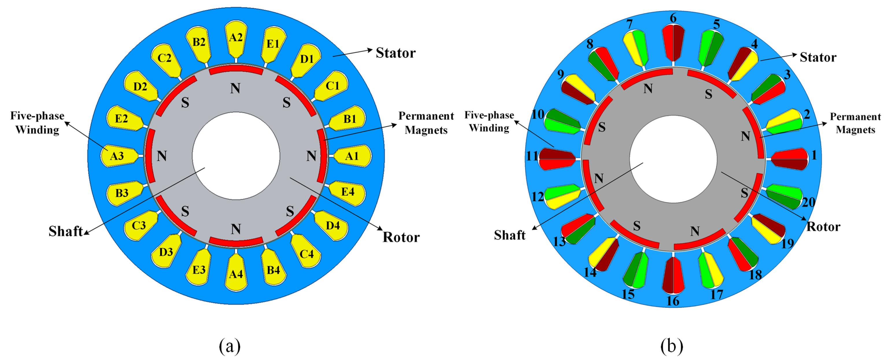
2.2. Winding Distribution
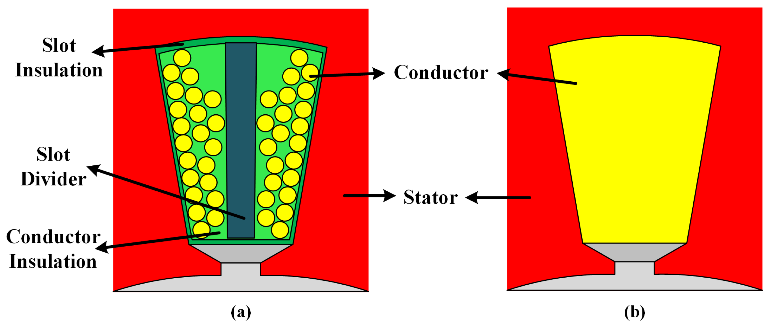
2.3. Motor Topology
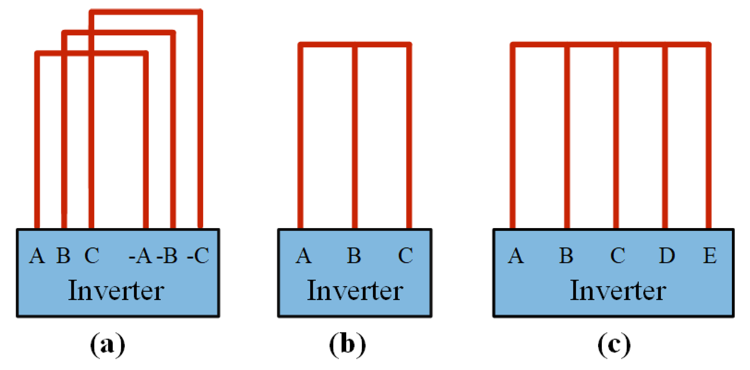
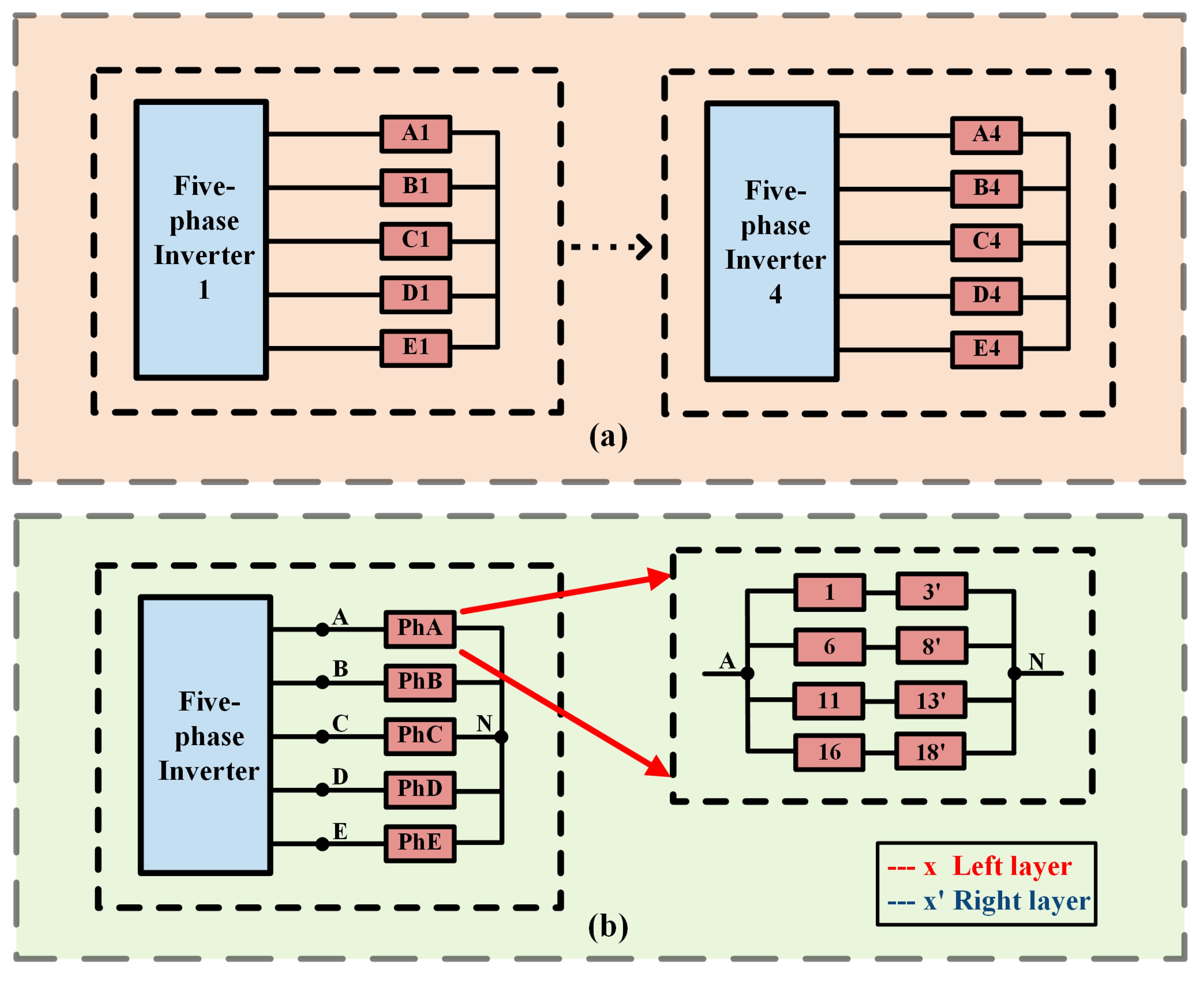
2.4. Driver Layout
2.5. Loss Analysis
3. Performance Comparison of MSPMSM with Different Motor Topology
3.1. No Load Simulation
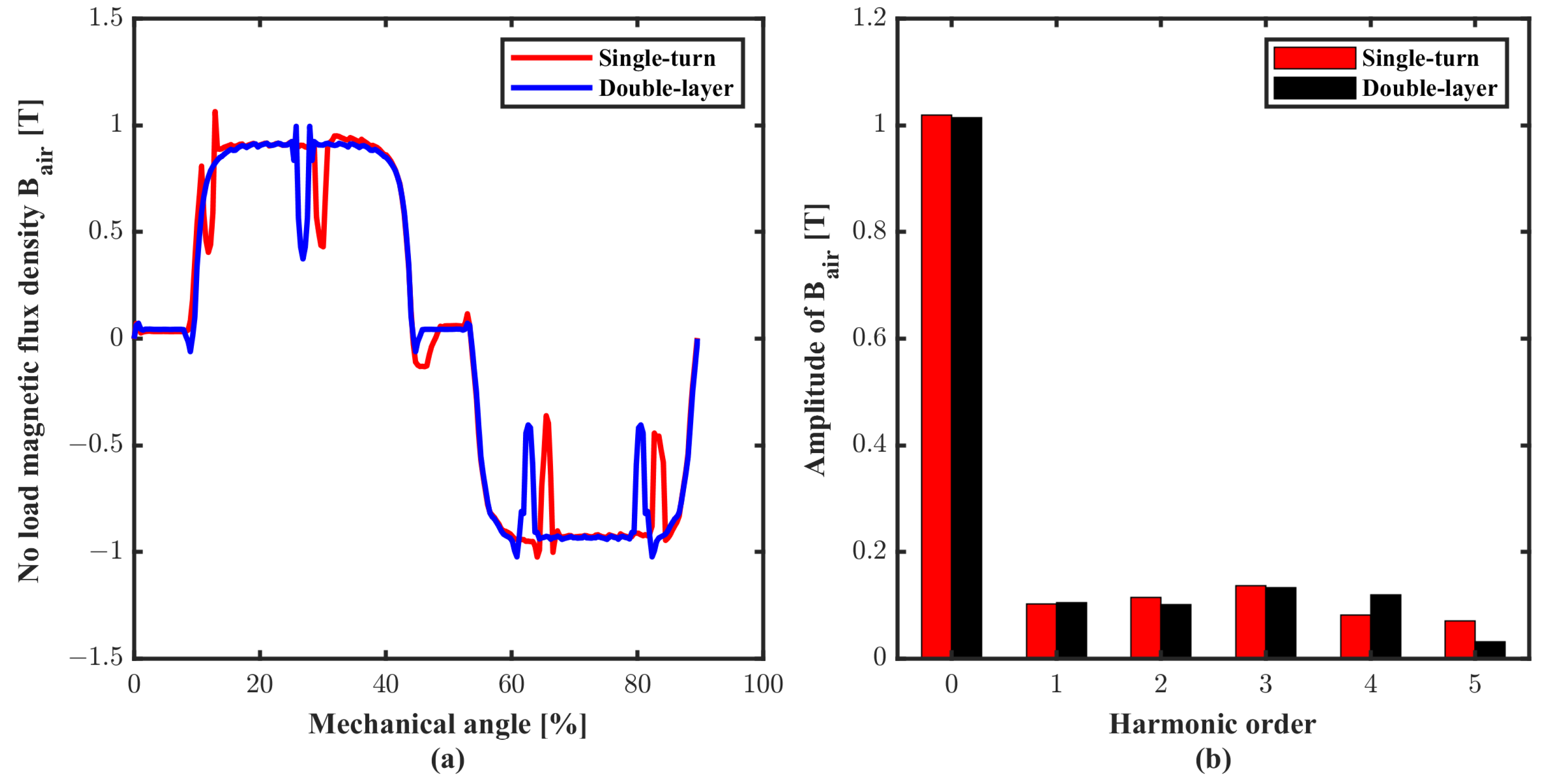
3.1.1. Comparison of Magnetic Field
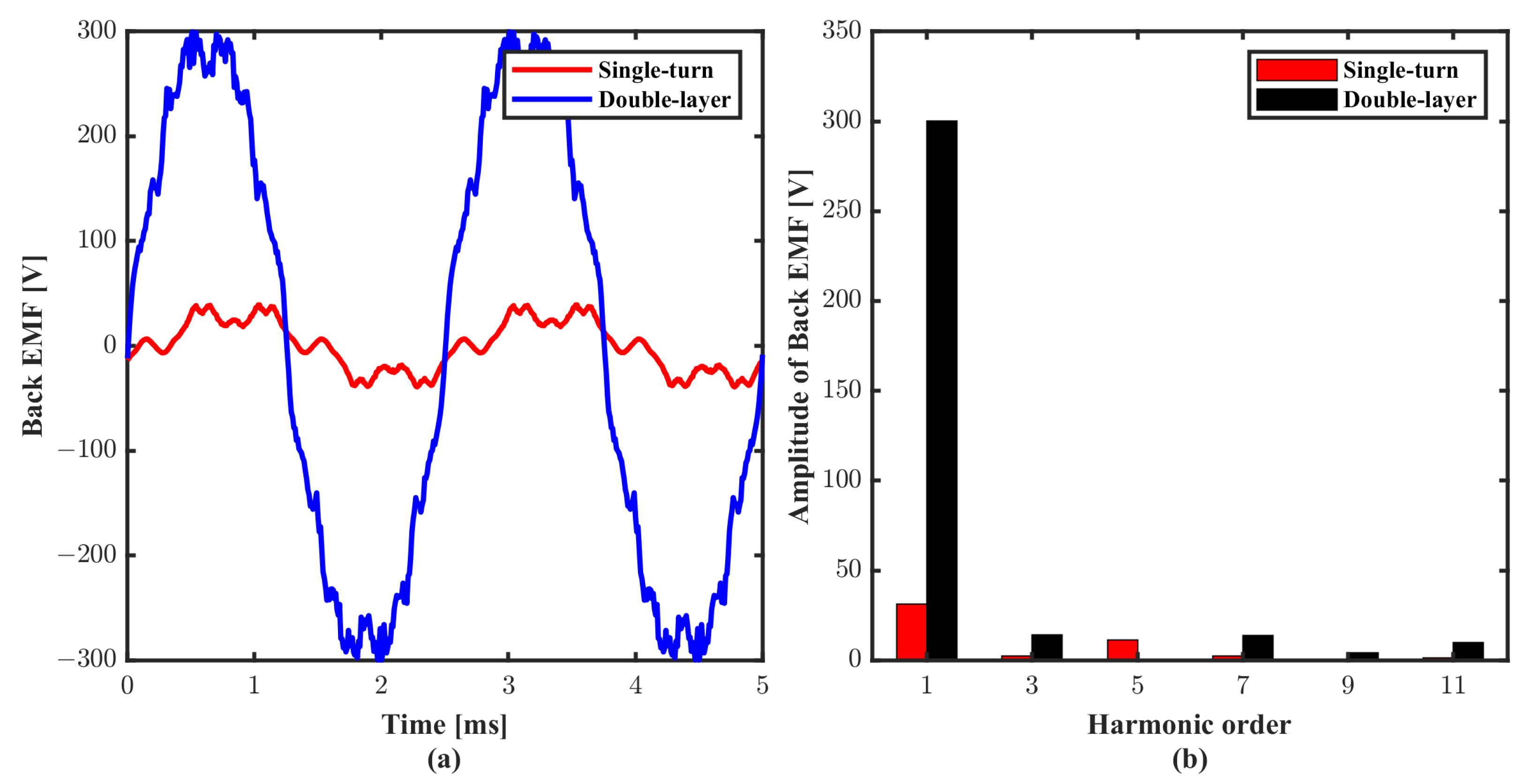
3.1.2. Comparison of Back-EMF
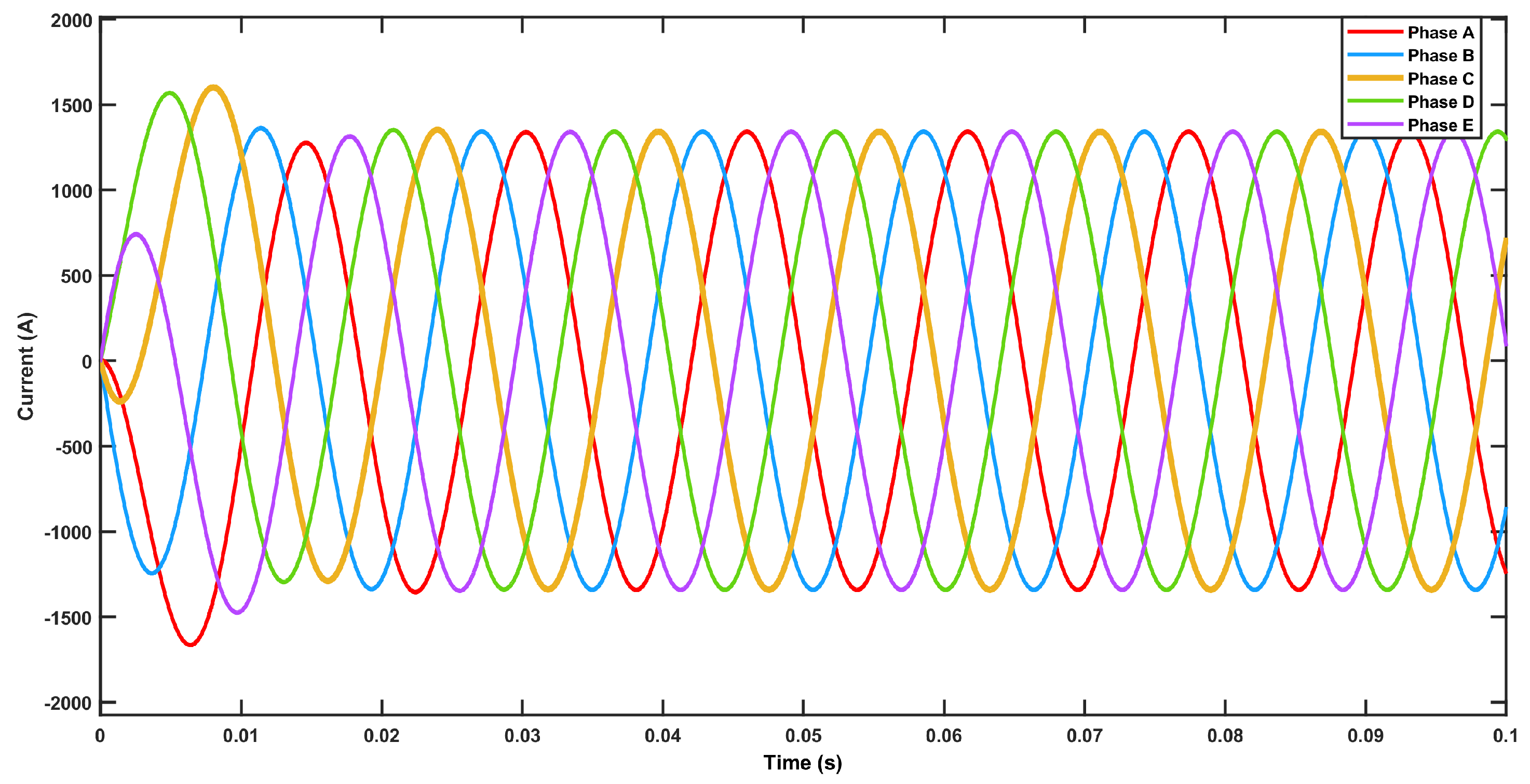
3.2. Load Simulation
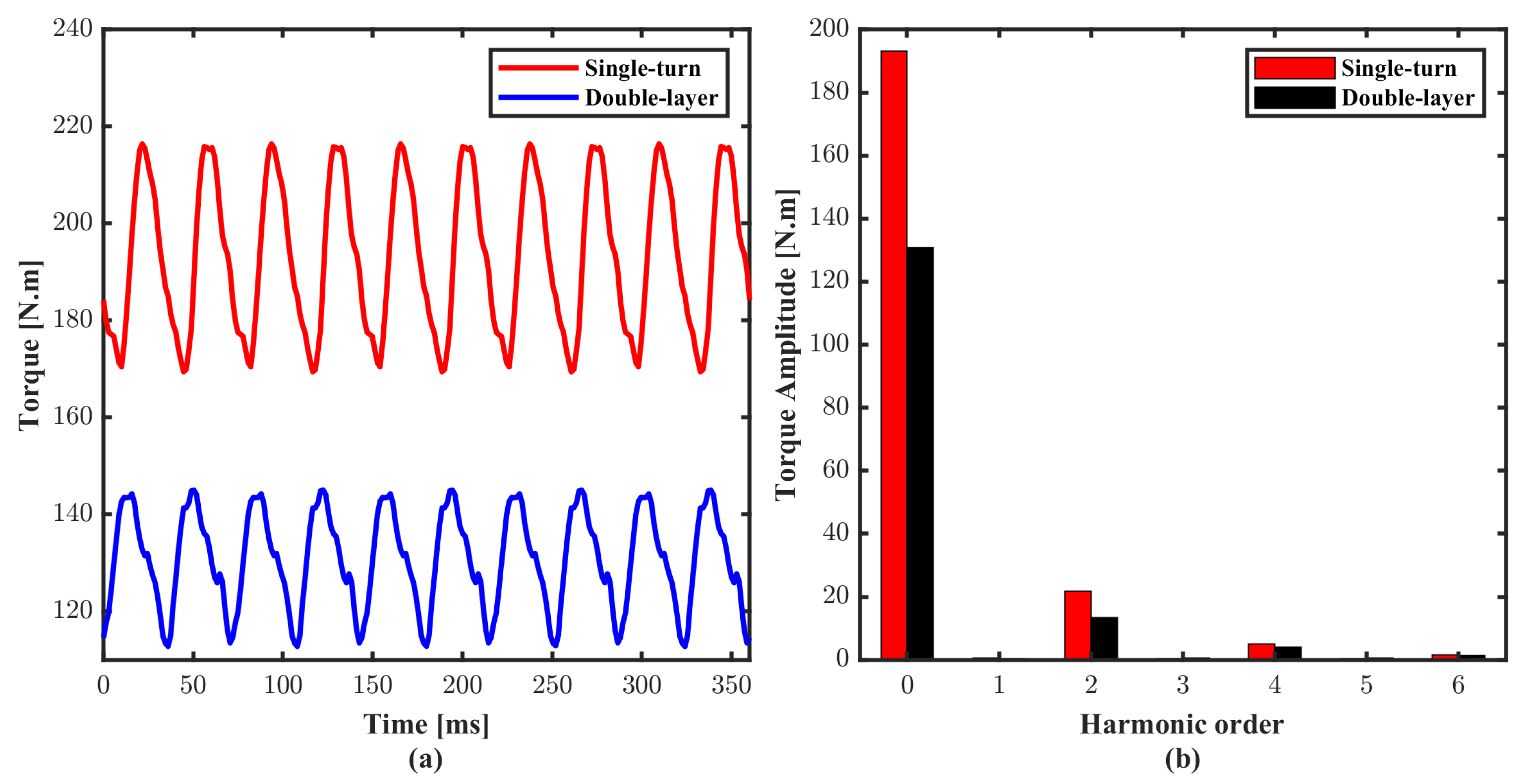
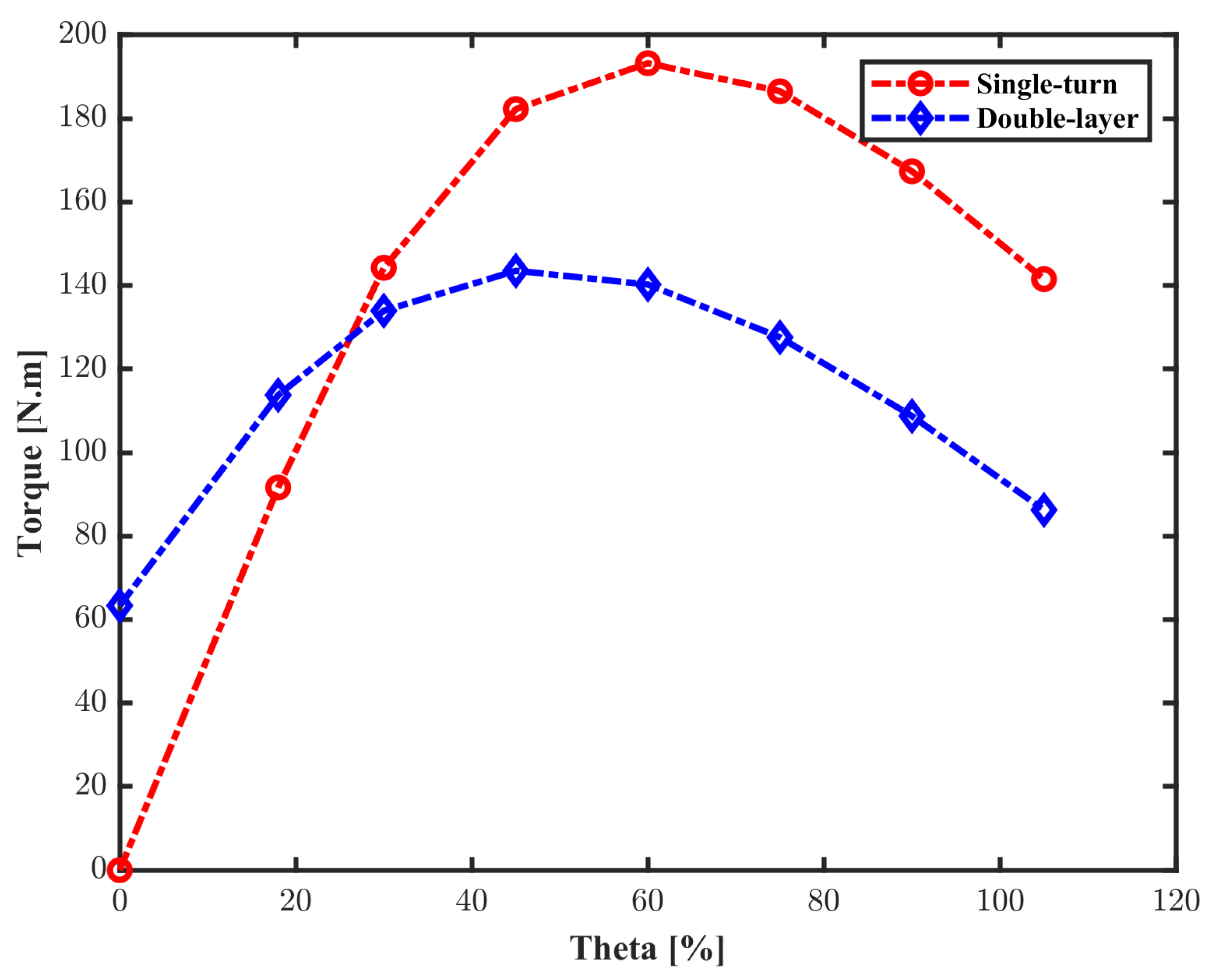
3.2.1. Comparison of Torque
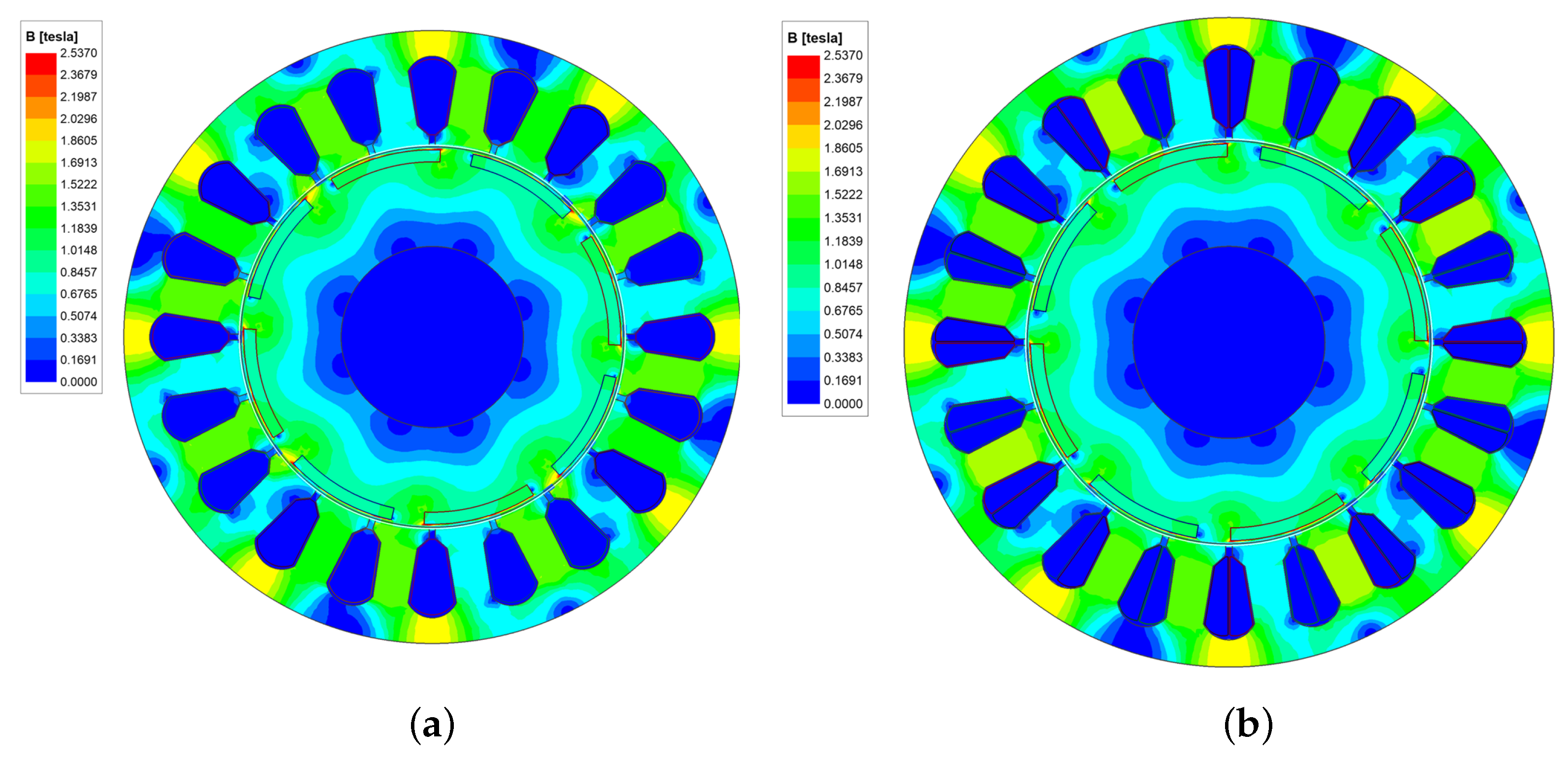
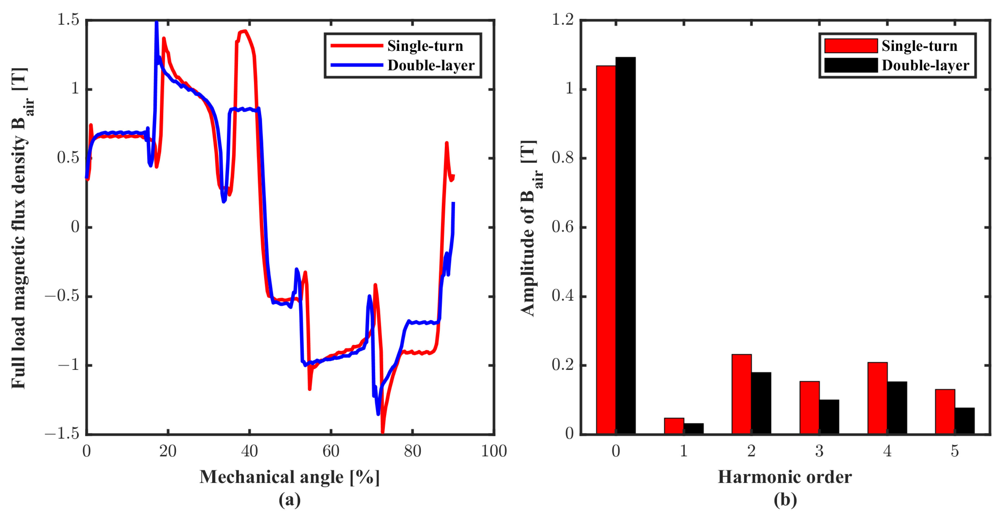
3.2.2. Comparison of Magnetic Field
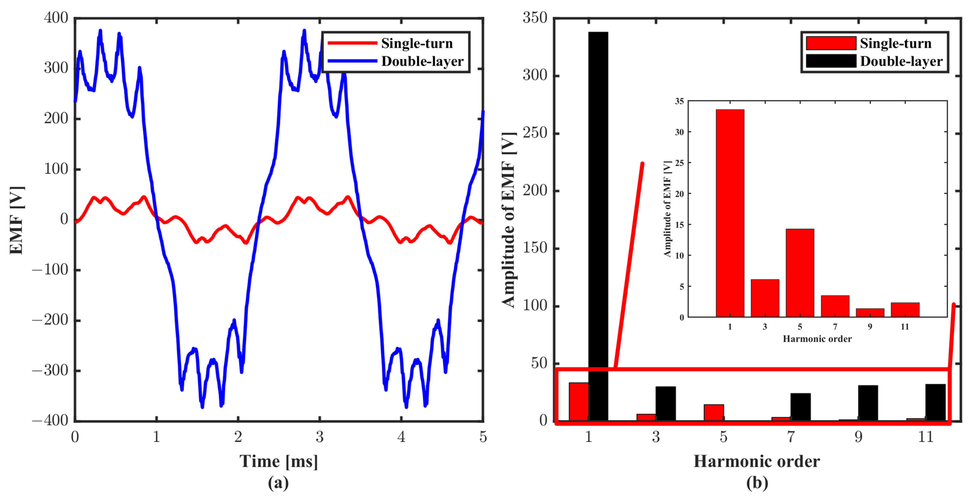
3.2.3. Comparison of EMF
3.2.4. Comparison of Losses and Efficiency
4. Conclusions
Author Contributions
Funding
Data Availability Statement
Conflicts of Interest
References
- Patterson, M.D.; Antcliff, K.R.; Kohlman, L.W. A proposed approach to studying urban air mobility missions including an initial exploration of mission requirements. In Proceedings of the Annual Forum and Technology Display, Phoenix, AZ, USA, 14–17 May 2018. [Google Scholar]
- Reiche, C.; Goyal, R.; Cohen, A.; Serrao, J.; Kimmel, S.; Fernando, C.; Shaheen, S. Urban Air Mobility Market Study. 2018. Available online: https://doi.org/10.7922/G2ZS2TRG (accessed on 21 November 2018).
- Hathaway, M.D.; Rosario, R.D.; Madavan, N.K. NASA fixed wing project propulsion research and technology development activities to reduce thrust specific energy consumption. In Proceedings of the Joint Propulsion Conference and Exhibit, San Jose, CA, USA, 14–17 July 2013. [Google Scholar]
- Cao, W.; Mecrow, B.C.; Atkinson, G.J.; Bennett, J.W.; Atkinson, D.J. Overview of Electric Motor Technologies Used for More Electric Aircraft (MEA). IEEE Trans. Ind. Electron. 2012, 59, 3523–3531. [Google Scholar] [CrossRef]
- Wheeler, P.; Sirimanna, T.S.; Bozhko, S.; Haran, K.S. Electric/Hybrid-Electric Aircraft Propulsion Systems. Proc. IEEE 2021, 109, 1115–1127. [Google Scholar] [CrossRef]
- Zhang, X.; Bowman, C.L.; O’Connell, T.C.; Haran, K.S. Large electric machines for aircraft electric propulsion. IET Electr. Power Appl. 2018, 12, 767–779. [Google Scholar] [CrossRef]
- Pavithran, K.; Parimelalagan, R.; Krishnamurthy, M. Studies on inverter-fed five-phase induction motor drive. IEEE Trans. Power Electron. 1988, 3, 224–235. [Google Scholar] [CrossRef]
- Guzman, H.; Duran, M.J.; Barrero, F.; Bogado, B.; Toral, S. Speed Control of Five-Phase Induction Motors with Integrated Open-Phase Fault Operation Using Model-Based Predictive Current Control Techniques. IEEE Trans. Ind. Electron. 2014, 61, 4474–4484. [Google Scholar] [CrossRef]
- Zhao, T.; Wu, S.; Cui, S. Multiphase PMSM with Asymmetric Windings for More Electric Aircraft. IEEE Trans. Transp. Electrif. 2020, 6, 1592–1602. [Google Scholar] [CrossRef]
- Casadei, D.; Mengoni, M.; Tani, A.; Serra, G.; Zarri, L. Torque maximization in high-torque density multiphase drives based on induction motors. In Proceedings of the 2010 IEEE Energy Conversion Congress and Exposition, Atlanta, GA, USA, 12–16 September 2010; pp. 3896–3902. [Google Scholar] [CrossRef]
- Xu, H.; Toliyat, H.; Petersen, L. Rotor field oriented control of five-phase induction motor with the combined fundamental and third harmonic currents. In Proceedings of the APEC 2001. Sixteenth Annual IEEE Applied Power Electronics Conference and Exposition (Cat. No.01CH37181), Anaheim, CA, USA, 4–8 March 2001; Volume 1, pp. 392–398. [Google Scholar] [CrossRef]
- Villani, M.; Tursini, M.; Fabri, G.; Castellini, L. High Reliability Permanent Magnet Brushless Motor Drive for Aircraft Application. IEEE Trans. Ind. Electron. 2012, 59, 2073–2081. [Google Scholar] [CrossRef]
- Villani, M.; Tursini, M.; Fabri, G.; Castellini, L. Multi-phase fault tolerant drives for aircraft applications. In Proceedings of the Electrical Systems for Aircraft, Railway and Ship Propulsion, Bologna, Italy, 19–21 October 2010; pp. 1–6. [Google Scholar] [CrossRef]
- Arumugam, P.; Barater, D.; Hamiti, T.; Gerada, C. Winding concepts for ultra reliable electrical machines. In Proceedings of the IECON 2014—40th Annual Conference of the IEEE Industrial Electronics Society, Dallas, TX, USA, 29 October–1 November 2014; pp. 959–964. [Google Scholar] [CrossRef]
- Anderson, A.D.; Renner, N.J.; Wang, Y.; Agrawal, S.; Sirimanna, S.; Lee, D.; Banerjee, A.; Haran, K.; Starr, M.J.; Felder, J.L. System Weight Comparison of Electric Machine Topologies for Electric Aircraft Propulsion. In Proceedings of the 2018 AIAA/IEEE Electric Aircraft Technologies Symposium (EATS), Cincinnati, OH, USA, 12–14 July 2018; pp. 1–16. [Google Scholar]
- Galea, M.; Buticchi, G.; Empringham, L.; de Lillo, L.; Gerada, C. Design of a High-Force-Density Tubular Motor. IEEE Trans. Ind. Appl. 2014, 50, 2523–2532. [Google Scholar] [CrossRef]
- Brown, N.R.; Jahns, T.M.; Lorenz, R.D. Power Converter Design for an Integrated Modular Motor Drive. In Proceedings of the 2007 IEEE Industry Applications Annual Meeting, New Orleans, LA, USA, 23–27 September 2007; pp. 1322–1328. [Google Scholar] [CrossRef]
- Wang, J.; Li, Y.; Han, Y. Integrated Modular Motor Drive Design with GaN Power FETs. IEEE Trans. Ind. Appl. 2015, 51, 3198–3207. [Google Scholar] [CrossRef]
- Wu, S.; Tian, C.; Zhao, W.; Zhou, J.; Zhang, X. Design and Analysis of an Integrated Modular Motor Drive for More Electric Aircraft. IEEE Trans. Transp. Electrif. 2020, 6, 1412–1420. [Google Scholar] [CrossRef]
- Liu, C.; Paul, K.; Zucker, O. Experimental Demonstrations of a Representative Motor and Linear Actuator Using Controlled Turn-Less Structure Arrays Motors (CTM). Available online: https://indi.to/87fLM (accessed on 6 June 2018).
- Zucker, O.S.; Blumenau, L.; Liu, C.; Yu, P.K. New High Specific Power Motor Technology for All-Electric Class III UAVs. In Proceedings of the 2018 IEEE International Power Modulator and High Voltage Conference (IPMHVC), Jackson, WY, USA, 3–7 June 2018; pp. 58–63. [Google Scholar] [CrossRef]
- Zucker, O. Electric Motor/Generator with Multiple Individually Controlled Turn-Less Structures. U.S. Patent Application 13/844,347, 28 November 2013. [Google Scholar]
- NASA. Strategic Implementation Plan 2019 Update. Technical Report. 2019. Available online: https://www.nasa.gov/sites/default/files/atoms/files/sip-2019-v7-web.pdf (accessed on 14 June 2020).


| Parameters | Value |
|---|---|
| Peak Power, P | 113 (kW) |
| Rated Speed, n | 6000 (r/min) |
| Average Torque, T | 191 (N·m) |
| Efficiency, | >94 (%) |
| Voltage, U | 48 (V) |
| Peak current, I | 1500 (A) |
| Parameters | Value |
|---|---|
| Number of slots, Q | 20 |
| Number of poles, p | 8 |
| Number of phase, m | 5 |
| Stator outer diameter, | 406 (mm) |
| Stator inner diameter, | 254 (mm) |
| Effective length, | 100 (mm) |
| Air gap, | 1 (mm) |
| Shaft diameter, | 120 (mm) |
| Steel material | DW310 |
| Magnet material | N30SH |
| Parameters | Single-Turn | Double-Layer |
|---|---|---|
| Slots/Poles | 20/8 | 20/8 |
| Number of phase | 5 | 5 |
| Current density (A·mm) | 4.7 | 4.7 |
| Current (A) | 1500 | 117 |
| Speed (r/min) | 6000 | 6000 |
| Slot fill factor | 1 | 0.78 |
| Magnet thickness (mm) | 8 | 8 |
| Number of turns | 1 | 5 |
| Parameters | Single-Turn PMSM | Doubel-Layer PMSM |
|---|---|---|
| 1.6 (m) | 13 (m) | |
| Maximum | 100 (V) | 750 (V) |
| Maximum | 860 (A) | 140 (A) |
| 20 (kHz) | 20 (kHz) | |
| 270 (ns) | 43 (ns) | |
| 175 (ns) | 14 (ns) | |
| 22 (nF) | 475 (pF) | |
| Cost for each MOSFET | 362 ($) | 49.9 ($) |
Disclaimer/Publisher’s Note: The statements, opinions and data contained in all publications are solely those of the individual author(s) and contributor(s) and not of MDPI and/or the editor(s). MDPI and/or the editor(s) disclaim responsibility for any injury to people or property resulting from any ideas, methods, instructions or products referred to in the content. |
© 2023 by the authors. Licensee MDPI, Basel, Switzerland. This article is an open access article distributed under the terms and conditions of the Creative Commons Attribution (CC BY) license (https://creativecommons.org/licenses/by/4.0/).
Share and Cite
Cheng, Z.; Cao, Z.; Hwang, J.T.; Mi, C. A Novel Single-Turn Permanent Magnet Synchronous Machine for Electric Aircraft. Energies 2023, 16, 1041. https://doi.org/10.3390/en16031041
Cheng Z, Cao Z, Hwang JT, Mi C. A Novel Single-Turn Permanent Magnet Synchronous Machine for Electric Aircraft. Energies. 2023; 16(3):1041. https://doi.org/10.3390/en16031041
Chicago/Turabian StyleCheng, Zeyu, Zhi Cao, John T. Hwang, and Chris Mi. 2023. "A Novel Single-Turn Permanent Magnet Synchronous Machine for Electric Aircraft" Energies 16, no. 3: 1041. https://doi.org/10.3390/en16031041