1. Introduction
Electrical machines are critical components of e-mobility applications, for which the ferromagnetic cores are one of the primary sources of losses. Reducing the core losses and increasing the power density of the machines is one of the main goals during the design process. A novel trend in electrical machine manufacturing is to create a robust design that will be insensitive to manufacturing intolerances [
1,
2,
3]. The robust design optimization procedure is numerically expensive, where the consideration of the tolerances on the main parameters of the machine significantly increases the number of calculated design cases. Moreover, the effect of small changes in the optimized parameters needs accurate numerical predictions and considerably more numerical calculations [
4,
5].
In ferromagnetic materials, the magnetic loss is based on Joule heating, which is generated by the motion of the magnetic domain walls [
6,
7]. Nowadays, most of the electrical machine design process contains finite element calculations. The most advanced calculation of the ferromagnetic losses can be made by those finite-element-based tools that use integrated mathematical hysteresis models (Preisach or Jiles–Atherton models), to directly estimate iron losses [
8,
9,
10,
11,
12]. Despite the high accuracy of these methods, their applicability for example, in the conceptual design optimization phase, is limited due to their high numerical cost. Moreover, these methods need a relatively high knowledge of the applied material, and the exact shape of the B–H hysteresis loop, which usually needs measurement and can be affected by many factors [
6]. These data are usually not available at the early design stage, when not only the geometric data but many other quantitative data are missing from the applied materials [
13].
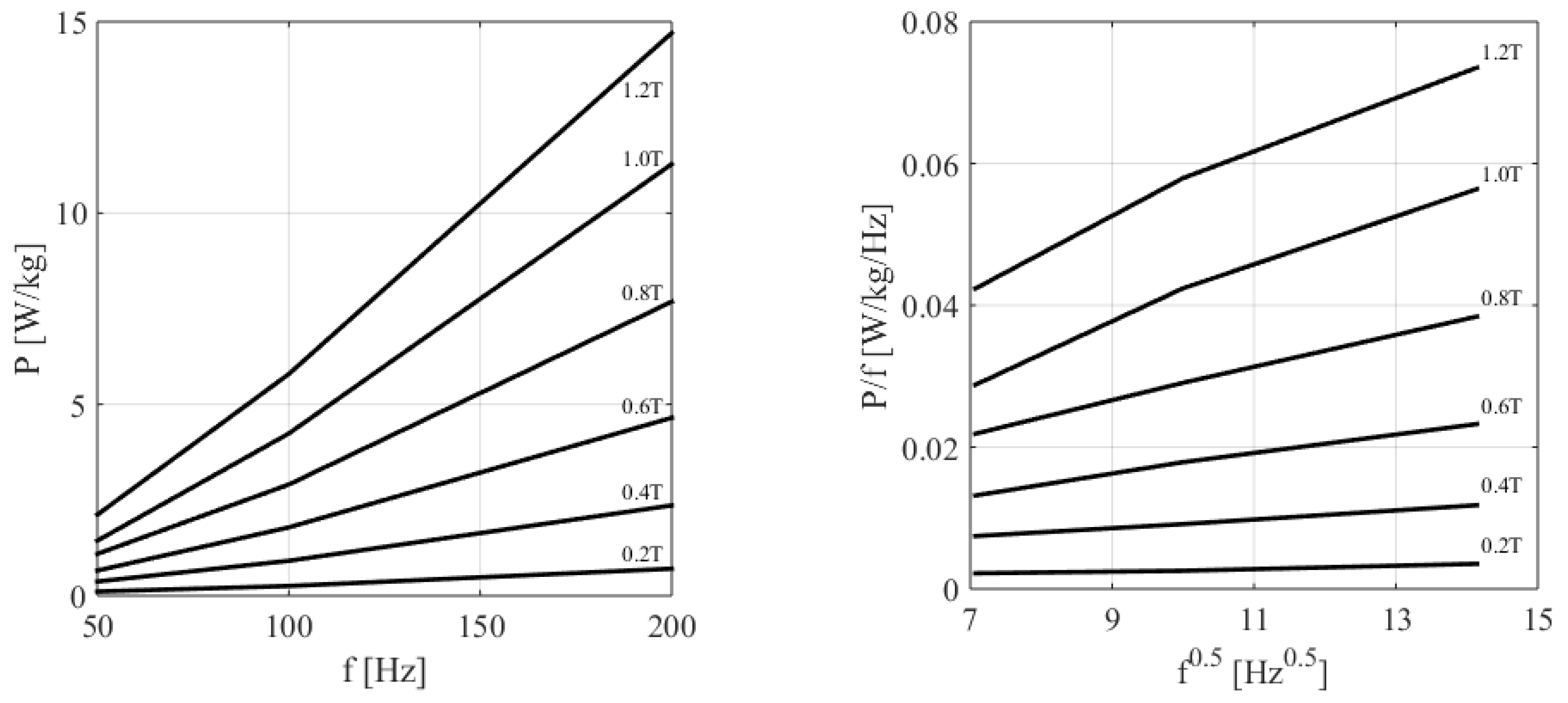
Most of the FEM tools use post-processing-based techniques to calculate the losses. These techniques contain measurement-based formulas, which approximate the loss as a polynomial function of the magnetic flux density. Many FEM tools use the loss separation model, which is based on the Steinmetz equation [
14,
15,
16,
17]:
where
P denotes the approximated losses, the frequency is denoted by
f, and
B means the amplitude of the magnetic flux density. The
C,
, and
are model parameters that can be determined from the measured data. These model parameters should be calculated for every considered frequency harmonics separately. This model assumes that the excitation has a pure sinusoidal magnetic flux density waveform. During a FEM-based calculation, the time-dependent magnetic flux density values should be considered for every finite element. The losses are calculated element-wise by post-processing these time-dependent magnetic flux densities using Equation (
1). This is a very easily applicable methodology, which can give accurate results when the magnetomotive force is sinusoidal. However, this condition is not fit for most modern electrical machine topologies and drive systems [
1,
5,
15].
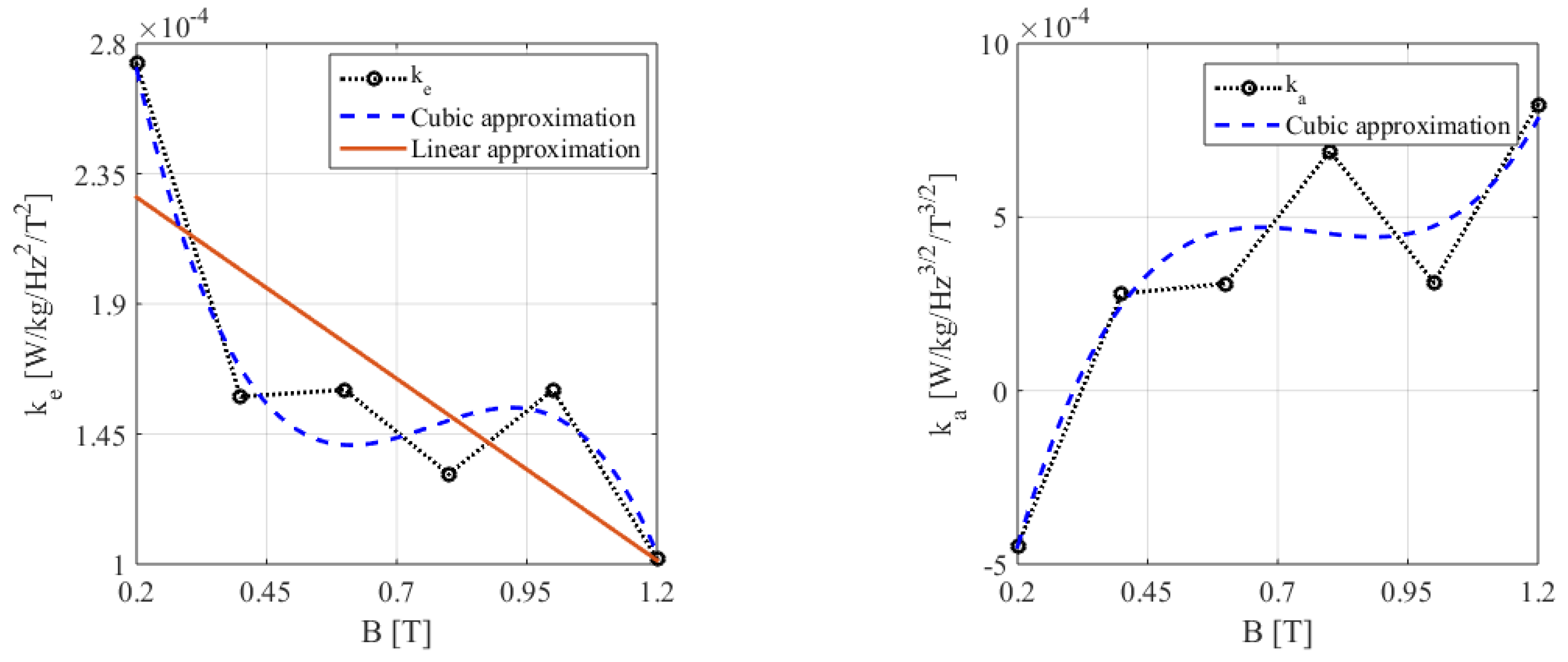
Jordan modified and extended the Steinmetz equation (Equation (
1)) to improve its accuracy, with the consideration of the eddy current losses generated in laminated steel sheets [
18]. This model assumes that different physical processes generate losses. It assumes that the sum of a static magnetic hysteresis and the eddy current loss of the laminations can calculate the losses:
Here, the first term represents the hysteresis losses (
), and the second term considers the newly introduced eddy current losses (
). The model contains two parameters that must be fitted into measured loss data. These are
and
. These iron-loss separation models assume that the hysteresis losses are proportional to the time-dependent magnetic flux density. This assumption is a weakness of this approach because the value of the hysteresis loss is not zero after a magnetization process at zero flux density. It can be seen that, in these cases, hysteresis-loss-approximation-based formulae generally over- or underestimates the momentary value of this term. Bramerdorfer proposed an improvement, a radial basis function-based nonlinear modeling technique, which uses the magnetic flux and its first-time derivative to consider the previous state of magnetization for the hysteresis loss estimation [
15]. The eddy current loss term can be derived from Maxwell’s equations, and it can be written in the following form:
where
B(t) is the time-dependent value of the magnetic flux density,
d is the thickness of the steel sheet,
represents its specific mass, and the
represents the specific conductivity of the steel sheet. The Jordan model (Equation (
2)) works well on a wide variety of nickel–iron alloys [
6,
7]. However, it is not accurate in the case of SiFE alloys, where a significant amount of excess loss was generated. These additional losses are usually described by a third term:
where the last term represents these additional excess losses. Bertotti introduced a statistic-based measure and a theory to calculate these excess losses [
19]. He interpreted this excess loss factor (
) with the grain size of the magnetic domains and their wall motion:
where
is the electric conductivity,
S is the cross-sectional area of the lamination,
takes the grain size and the local forces into account, and
G is a material constant whose value is about 0.136 [
7,
20].
However, rotational losses affect iron losses in electrical machines. Many papers consider how these losses can be considered with the modified version of this formula (Equation (
4)) [
21,
22,
23]. The cutting and punching processes of the iron sheets significantly influence the material properties and create inhomogeneous stress in a narrow region of the core material. The thickness of this region is estimated using electron microscopy, and it is around 100–150
m, where the magnetic properties change significantly. Moreover, stacking and welding the iron sheets during machine core assembly also increases iron loss. All of these manufacturing processes increase iron loss, which must be considered in modeling and design [
6,
7,
24]. This most commonly used iron-loss separation model (Equation (
4)), or its modifications, is integrated into many commercial FEM tools. These tools usually use additional steps during the processing. For example, they use different frequency separation approaches to determine the losses. Nevertheless, these tools allow the users to define these material parameters for loss separation models using Equation (
4).
There are two possible ways to calculate these model parameters. First, we can use the technical datasheet of the electrical steel, typically obtained by using a standard Epstein frame, and provide some maximum guaranteed values and typical average values of magnetic properties [
6,
7,
16,
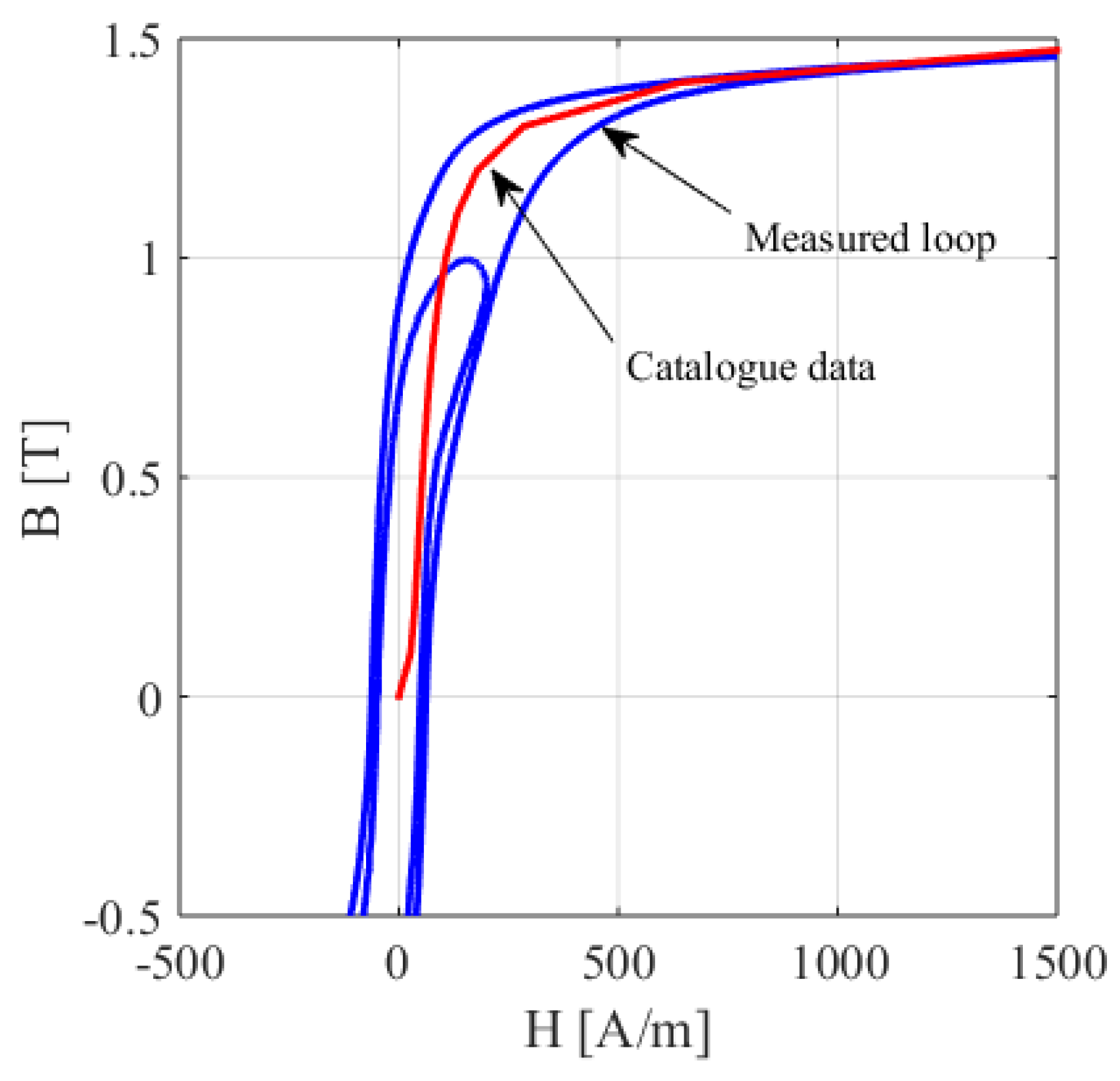
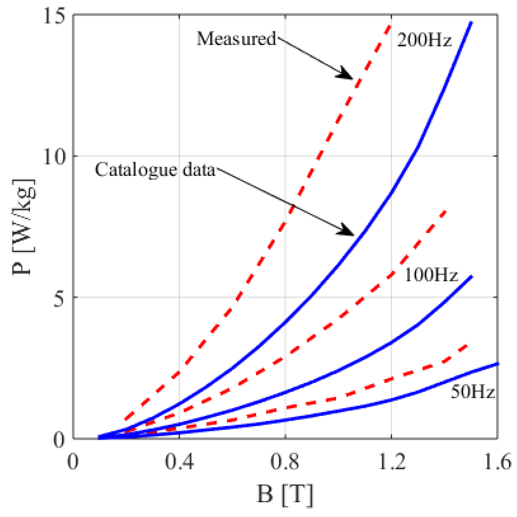
17]. The main problem with iron loss measurement is that the catalog data can only partially estimate iron losses. The factory and standardized measurements are taken with a standard Epstein frame on relatively large lamination sheets with regular shapes cut from a stack of plates produced by rolling, regardless of the use of iron plates.
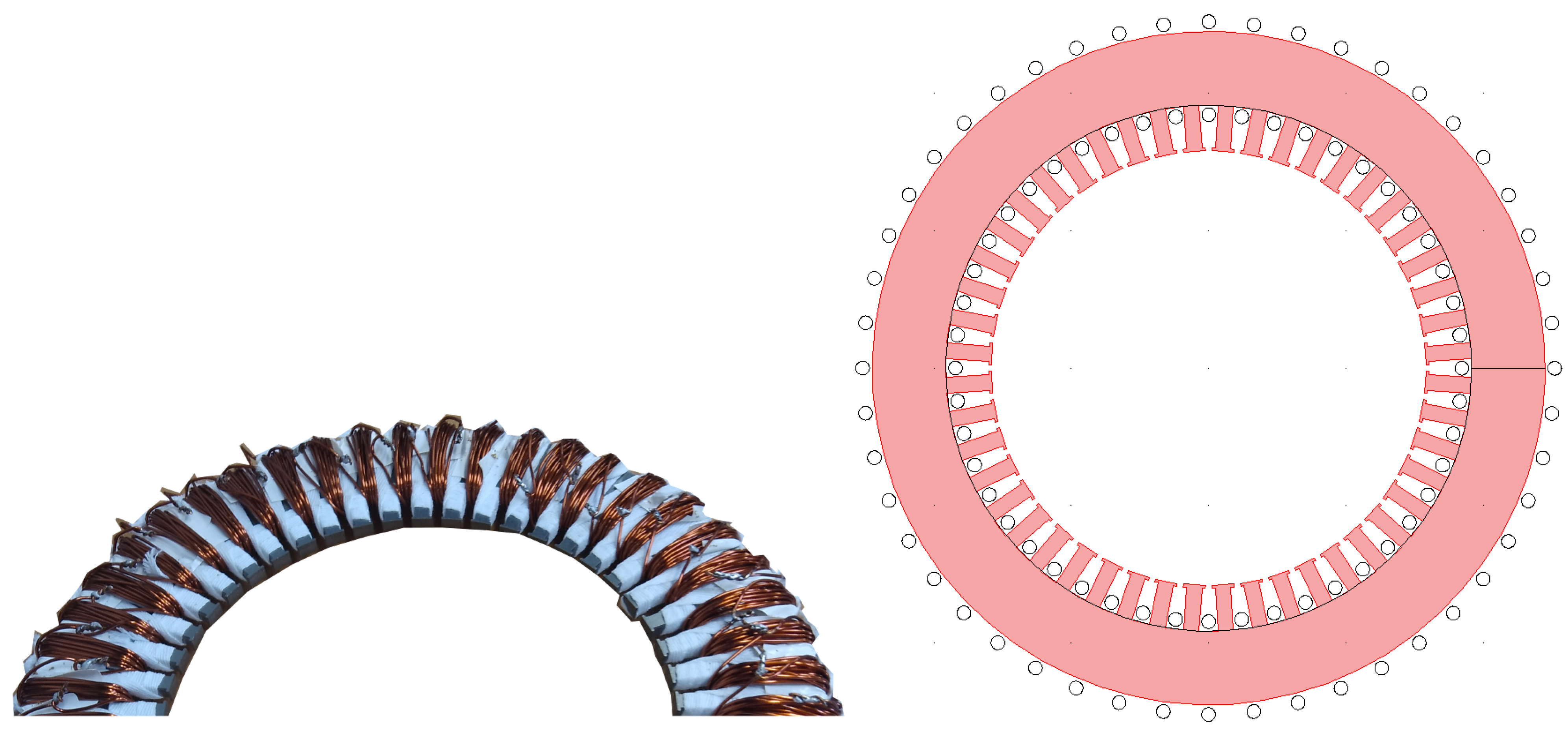
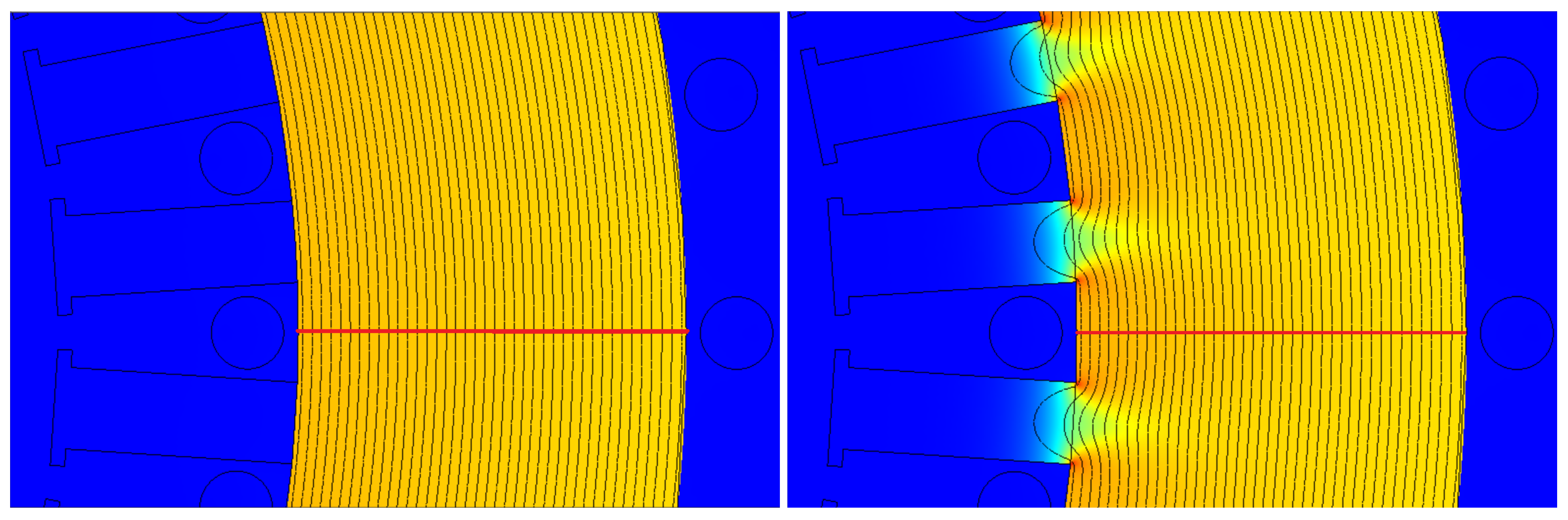
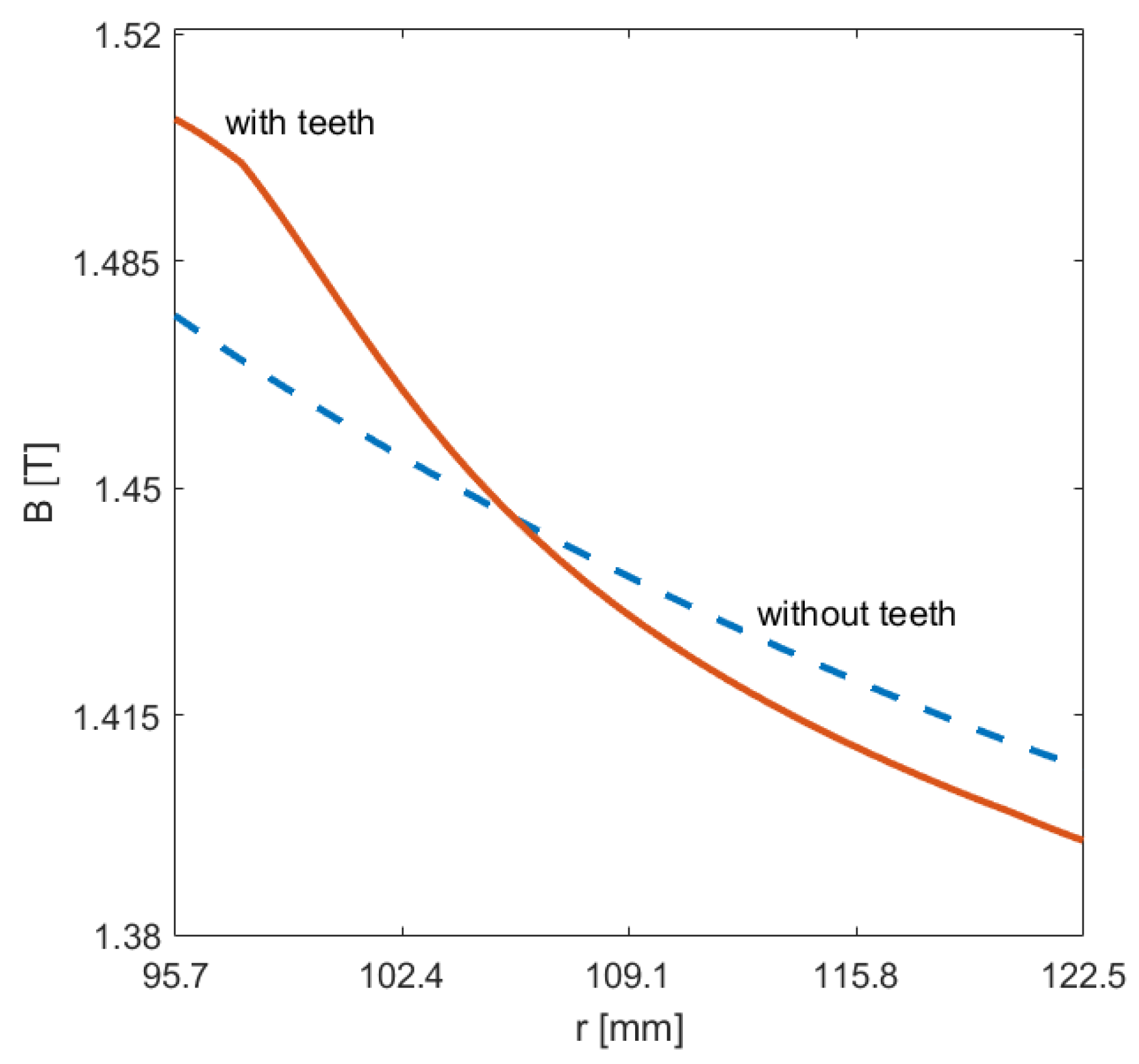
By contrast, stator elements usually contain many slots that are cut from iron plates. The impact of mechanical influences (e.g., cutting, joining) all modify the ferromagnetic material’s hysteresis characteristics and significantly affect the losses. Therefore, customized laboratory measurements will undoubtedly result in higher and more accurate loss calculations than standardized measurement-based calculations. Different methods can be used for these customized laboratory measurements; it can be used as an Epstein frame [
16,
17,
25] or a toroidal-shaped core transformer [
26], which can accurately take these extra losses into account during the design process.
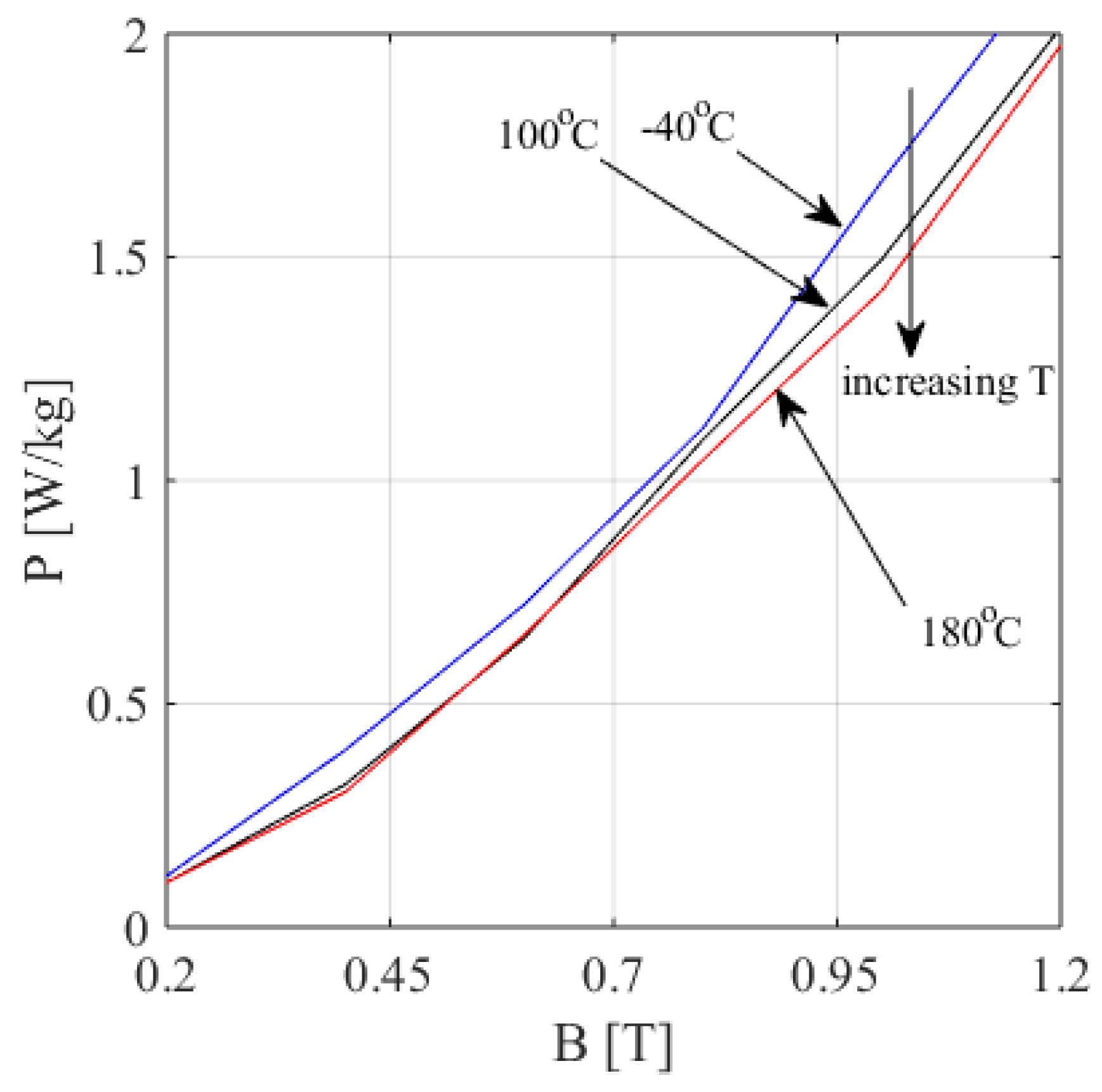
The previously proposed models have their best performance at a constant temperature. Some recent research examined the temperature dependence of these iron loss parameters. The first group of the temperature-dependent iron-loss separation models assumed that the temperature affects the eddy current of the iron-loss model due to the temperature dependency of the electric resistivity [
27]. In [
22,
28], the authors examined the temperature dependence of non-oriented silicon steel laminations till 100 °C. Their model assumed that the magnetic permeability of the examined steel depends on the temperature. Therefore, not only the eddy currents but also the hysteresis losses change by the temperature. The authors showed that both the hysteresis and eddy current losses change linearly as a function of the temperature.
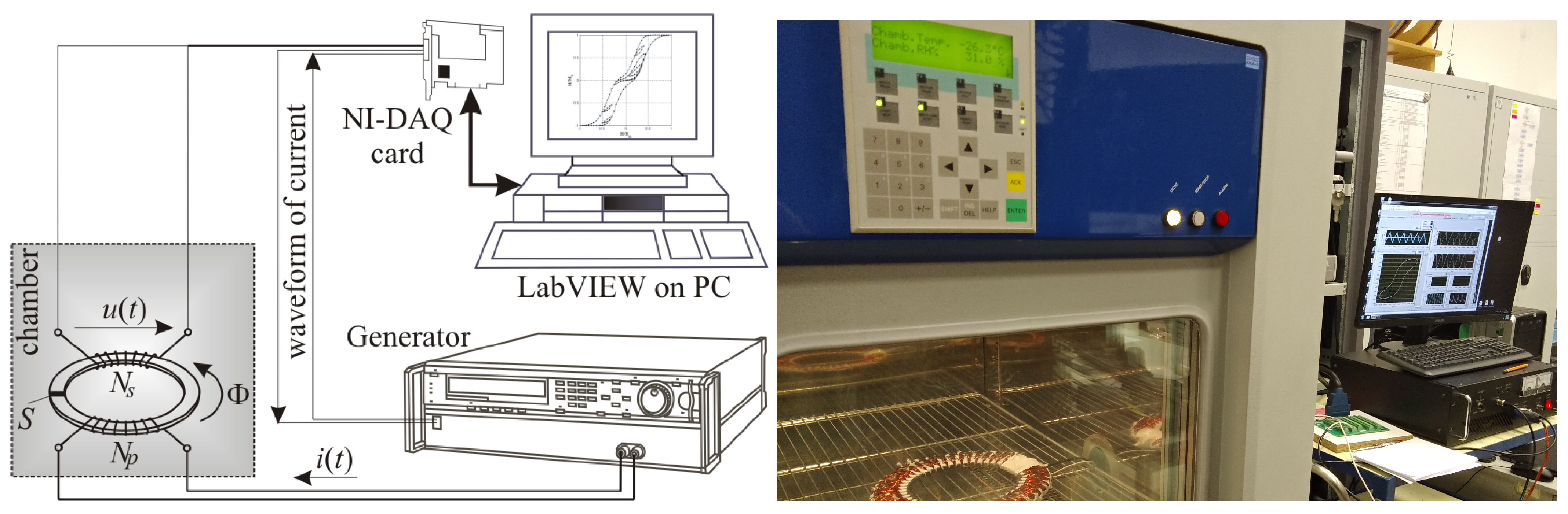
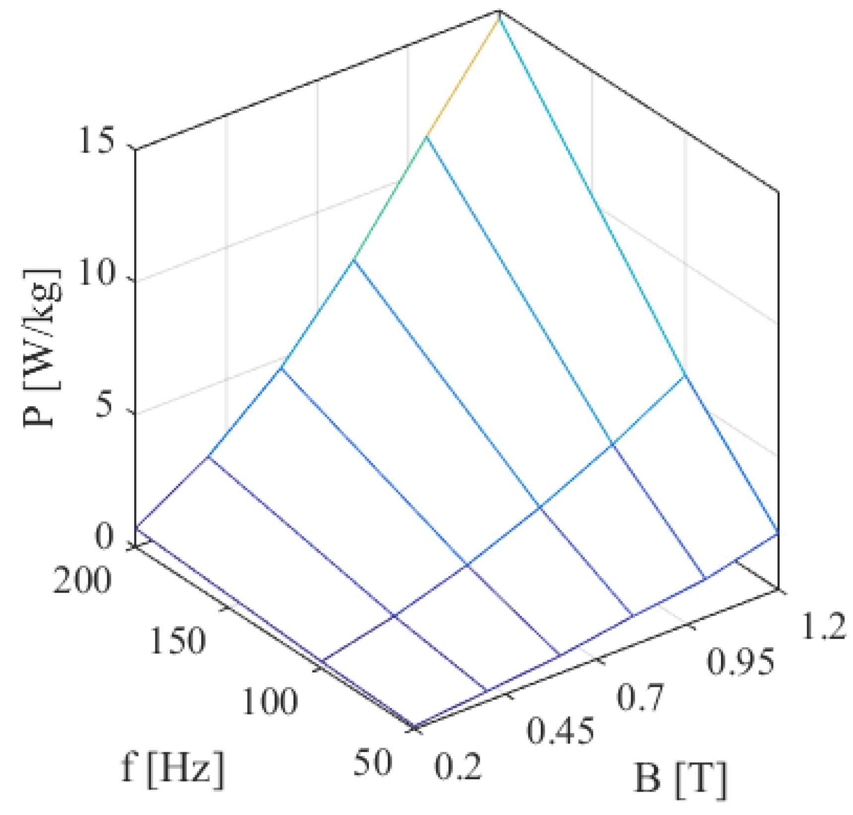
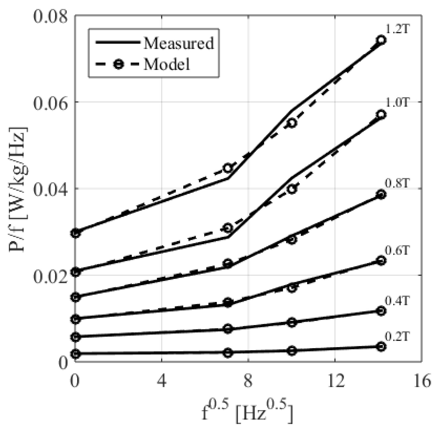
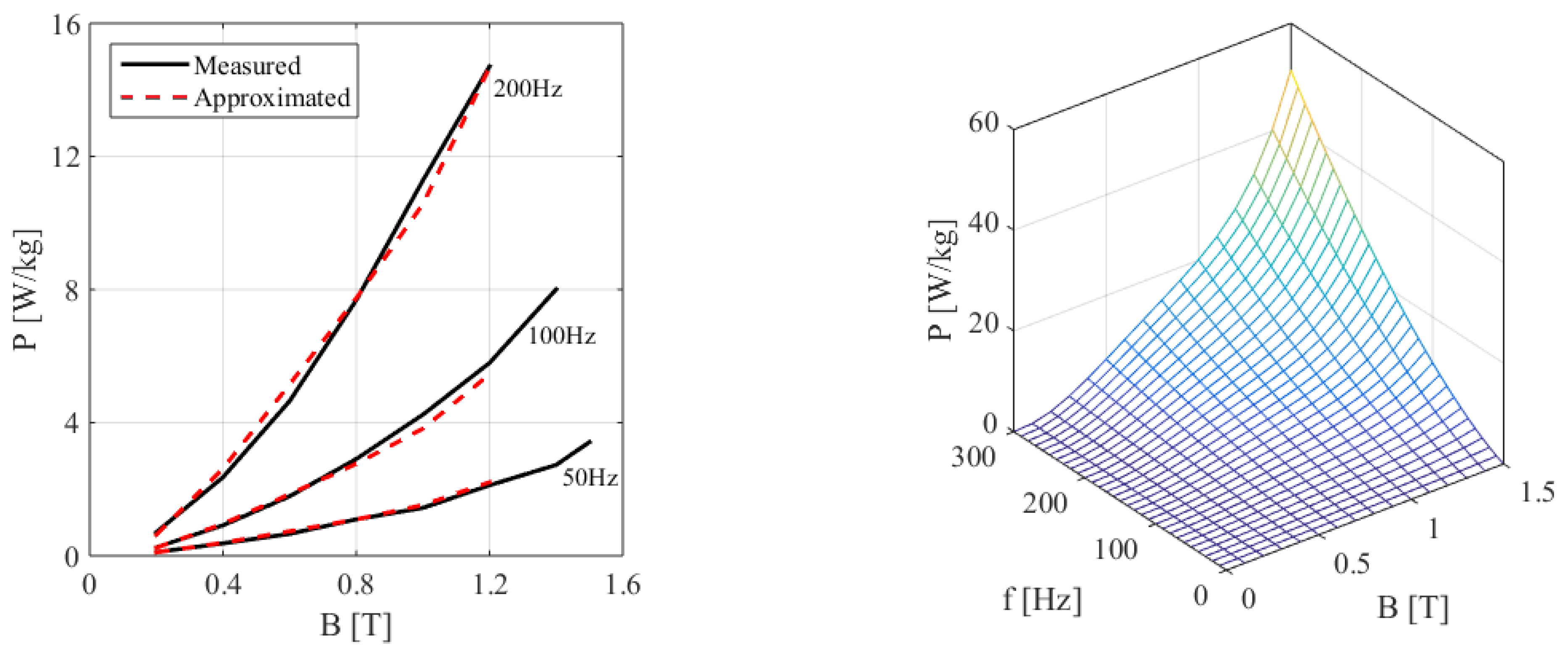
This paper proposes a novel measurement setup that can examine the temperature dependence of an induction machine in a wider range, up to 200 °C, than discussed in previous studies, and a temperature-dependent model is given based on the loss separation principle and validated by the measurements. Moreover, this paper compares the losses calculated based on standardized Epstein frame measurements (catalog data) with the results from customized laboratory tests. It is shown that the loss in the examined stator is much higher due to the effects of manufacturing, and the customized laboratory-measurement-based calculations give a significantly better estimation for the losses. This paper aims to show a step-by-step approach to making a customized, ferromagnetic loss model that can handle temperature dependency for further optimization of the machine. The resulting ferromagnetic model can take the temperature dependency of a material during a 2D FEM-based optimization of the machine. The proposed model can be used in the post-processing stage of finite-element-method-based modeling to obtain losses in the core material.
5. Conclusions
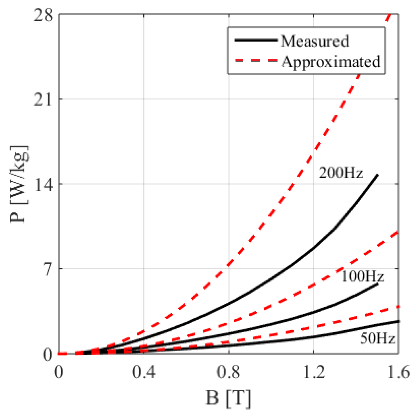
Most industrial and scientific applications use post-processing analysis to make an accurate ferromagnetic loss calculation. This methodology usually underestimates or overestimates the losses due to neglecting the exact shape of the hysteresis curve. In this paper, we described the analysis and identification of an analytical iron loss formulation. Furthermore, a comparison of simulated and measured data was presented. Laboratory measurements are necessary for different temperatures and frequencies to determine the exact hysteresis characteristics. A measurement system was set up to study the electromagnetic loss inside the stator core material of an electrical machine, which was assumed to be a function of magnetic flux density, source frequency, and temperature. These data were used to approximate and extrapolate the loss values more precisely.
The proposed measurement differs from Epstein-apparatus-based measurements, for which the manufacturers measure the losses on a standardized material sample. Nevertheless, during the assembly of an electrical machine, many thermal, mechanical, and chemical stress affect the applied materials, and these effects can significantly increase core losses. Our laboratory tests aimed to make a more accurate loss calculation inside the ferromagnetic core, which increased by more than 50% based on our measurements in comparison to the catalog data. A further study needs to be carried out in order to calculate iron losses in the case of an existing electrical machine and compare the resulting losses with the standardized measurement-based calculations to show the overall performance of these numerical models on an existing machine. The resulting scalar hysteresis model takes into account the applied material’s temperature dependency. The measured and simulated data showed good agreement. The proposed model can be used directly for post-processing iron losses in the FEM solver. These models can accurately estimate losses in electrical machines that have non-sinusoidal excitation. However, the proposed methodology can be only applied for further design optimization or fine-tuning of the machine when we have a preconceived design and a manufactured prototype, based on which we can make customized measurements.


