1. Introduction
Fossil fuels make up 80% of the world’s primary energy supply, and this contributes to the increase in carbon dioxide levels and the global average temperature. To minimize the effects of global warming and climate change, the integration of renewable technologies is essential. Given this, demand in 2018 for energy from renewable sources increased by 4%, accounting for almost a quarter of the global increase in energy demand [
1]. According to the same author, the generation of photovoltaic (PV) solar energy reached a record, growing 31%. In addition, renewable sources also contributed to the growth of the energy sector, with generation increasing by 7% (about 450 TWh) of the equivalent of the total electricity demand in Brazil.
Renewable generation sources that show the most significant growth are solar and wind. Nevertheless, they are resources with greater generation variability due to dependence on climatic factors, which may create some technical and economic challenges for their operation and use when integrated on a large scale. The intermittence of renewable energy sources can be solved by inserting energy storage systems (ESS). ESS supports a wide range of services, such as frequency regulation, capacity reserve, harmonic suppression, voltage support, power quality, renewable energy integration and improving reliability and flexibility of the electrical system [
2,
3,
4].
Energy storage systems can store the energy in different ways for later application of services. Hence, electrical energy can be converted and stored as chemical, thermal, mechanical, electrical, or electrochemical energy. This type of system has three main applications in the large-scale systems sector: power quality, transition power, and power management [
5,
6,
7], as listed in
Table 1. The main difference between them is the timescale on which they operate and the extent to which power and energy are required.
When analyzing energy storage technologies, it is observed that electrochemical batteries are present in all categories and applications of
Table 1. Their application versatility is because they are currently found in electric vehicles, power systems, renewable energy integration, and general large-scale systems. The Battery Energy Storage System—BESS also has an advantage over other storage technologies, as it requires less space and few constraints on the geographic locations in which it could be installed, in addition to its modular construction, allowing the increase in energy and power later. Other storage technologies, such as hydraulics and compressed air, have more significant limitations, considering the need for a large area close to rivers and access to the transmission network.
In Brazil, the application of microgrids for maintenance of continuous operation in transmission substations that are outside the supplied standard of alternating current (AC) auxiliary systems is the most notable. The auxiliary system of an SS has the important function of ensuring the supply of electric energy for equipment that operates using DC (direct current) and AC. This equipment performs the functions of protection, control, and supervision of the substation. Thus, there are certain types of loads that are essential and must be fed as a priority, and there are also non-essential types that may suffer interruptions for longer.
According to the Brazilian Electrical System Operator—ONS, the auxiliary systems must be guaranteed by two power supplies, with the requirement that one of them comes from an external source. It is assumed that the requirement for an external source of supply occurs when the installation is supplied by the local distribution network. In some cases, the loads are supplied by two local external sources coming from feeders of the same substation, which does not guarantee independence between the sources. This results in compromising the reliability of the installation [
8]. However, there must also be a diesel generator (DG) with an automatic start capable of supplying the SS essential loads. It should be noted that the recurrent adoption of the use of DG to respond to cases of severe contingency does not eliminate supply interruptions, as its action begins after verifying the absence of grid voltage. In addition, there are records of failures during its initialization [
9].
As a means of increasing the reliability of the auxiliary service of the transmission substations, the ONS directs the agents responsible for the SS to study and adopt alternative supply measures or solutions with redundancy. Among the possibilities are the use of energy storage systems and renewable generation through microgrids, since Brazil has great solar potential for the use of photovoltaic and wind power plants. This alternative also presents other applications that justify its costs and combine the potential reduction of the operating costs of substations.
The public call for a photovoltaic mini-generation with energy storage by batteries as an autonomous source of supply of 230/500 kV substation auxiliaries systems with internal source constraints was launched by the Companhia Hidro Elétrica do São Francisco—Chesf [
10]. The approved proposal was the project entitled “Technical Arrangement to Increase Electrical Reliability and Safety, Applying Energy Storage by Batteries and Photovoltaic Systems to the Auxiliary Systems of 230/500 kV Substations”. To solve this electrical system problem, a microgrid composed of a photovoltaic plant and a hybrid energy storage system was proposed through the approved project.
The microgrid in question acts as an autonomous internal source of the substation, ensuring the continuous connection of auxiliary systems. This substation is part of the Brazilian transmission system, supplying the connection of the states of Alagoas and Pernambuco, which have an area equivalent to countries like Angola and Portugal, respectively. Given the importance of the system, the projected microgrid consists of a PV plant and a hybrid energy storage system using batteries. The HBESS was planned to promote security to the SS served, containing a battery technology for power operation and quick response and another technology for energy availability with autonomy of up to 9 h. The designed storage solution follows the financial and technical cost protocols made available by the responsible local electrical agency.
The contribution of this research, as will be observed in the article, is the development of the Energy Compensation Method for sizing the HBESS, based on the difference in energy density (W/kg) between electrochemical battery technologies. The formulation of the method is justified by the difficulty in sizing the total energy capacity of the system, as well as the percentage of energy that each battery technology will have. Furthermore, the main contribution is followed by the development of a new application, the use of HBESS in a transmission substation through a microgrid to continuously feed the auxiliary services that allow the substation to continue maintaining connections. No other similar project has been found so far in the country.
The remainder of this paper is divided into the following sections: the issue is formulated in
Section 1, and the theoretical foundation on electrochemical batteries and their characterization is presented in
Section 2.
Section 3 discusses the development of a sizing method for hybrid battery energy storage systems. Subsequently, in
Section 4, the proposed method is applied in the case study of the design of the HBESS for a microgrid to support the Messiah transmission substation. The conclusion regarding the development of the research is found in
Section 5.
2. Theorical Foundation
The characterization of HBESS is based on the battery technologies used. These batteries can be lithium-ion (Li-ion), sodium–sulfur (NaS), nickel–cadmium (NiCd), lead–acid (PbA), lead-carbon (PbC), nickel sodium chloride (Na-NiCl
), or flow types [
3]. Each battery category has countless unique characteristics, but the most important technical parameters for classifying batteries for HBESS are in relation to energy and power [
11]. This way, one can compare the lithium-ion battery with high power to the lead-carbon battery with high energy, for example.
Another essential parameter is the discharge duration of the storage systems shown in
Figure 1, which is categorized into short, medium, and long-term. Short-term energy storage (e.g., supercapacitors and flywheels) discharge from a few milliseconds to minutes. Medium-term technologies, such as chemical batteries, have discharge times ranging from a few minutes to hours. The discharge rates (C-rate) of lead–acid batteries are in the range of 10 h (0.1 C), and lithium batteries are in the range of 2 h (0.5 C) [
12].
HBESS is usually composed of a system dedicated to power application (HBESS) with characteristics of fast response time, high efficiency, and high cycle life. The other system is dedicated to energy application (HBESS) with characteristics of long discharge time and low cost. The application of this system is indicated for the integration of large distributed generation plants, installations with loads of motors and compressors, isolated microgrids, and the supply of long hours of contingency energy. This solution shows its benefits through the combination of energy and power from two systems, each of which operates optimally, supplying the applications most compatible with its characteristics. The physical concept of HBESS is defined by the possibility of adopting different topologies with the use of one or more converters. Additionally, logic programmers can be used to implement power management and control resources. The topology and components are determined by the application’s and operation’s needs. Batteries must be separated by technology to maintain system security. The most viable and safe topology is composed of two DC/AC converters, each of which is coupled to a system of batteries and connected in parallel. This approach is considered especially sensitive to the installation to which it will be connected. In this case, the system is managed by a local energy management system—EMS that monitors and controls the use of each battery string based on energy and power applications, together with information on load needs.
2.1. Battery Technologies and Applications
The feasibility of using an energy storage technology must be assessed based on the specific application the system will perform. Some applications can be categorized based on the duration of the discharge (long or short) or the frequency of occurrence of the discharge (high or low). If there are multiple applications, they will all be considered in the evaluation. The duration of the discharge is dependent on the energy and power requirement of an application. When the energy storage system needs to have a sufficient capacity for prolonged discharges (one or more hours), it is due to use in energy applications. Unlike long-term applications, short-term applications can load or unload quickly (from a few seconds to several minutes), considering power services [
13].
The applications are presented based on the discharging time and the frequency at which it occurs.
Figure 2 shows how the frequency is characterized by occurrences above twenty times a year. When evaluating this form of storage technology, consideration should also be given to the response time (
), which is the speed with which a storage technology can start operating, when on standby and when the unloading process begins. The last parameter is significant for some applications, such as backup (revolving reserve) and power smoothing from renewable sources.
To evaluate the battery response time, it is important to consider the average time required by applications. For the case of voltage stability, the energy storage system must act with nominal power and provide a minimum discharge of 1 s in
= 20 milliseconds, characterized as a power service. This requirement must be met even when the voltage smoothing power from renewable generation systems occurs. There is a backup element that must act within minutes to an hour, with a response time of 20 milliseconds. Other services also follow these characteristics, such as support for the network’s frequency and power quality [
13].
It is a large challenge to identify the best battery technology, since now, there are hundreds of different batteries available on the market, with varying characteristics and performance indices, depending on the raw material used and the manufacturing quality. There are still variations for each technology depending on voltage level, depth of discharge (DOD), and charging and maintenance requirements. It is therefore possible to state that there is no single technology that has a complete advantage over another, meeting all possible applications of energy and power. Consequently, the use of hybrid energy storage systems stands out due to the combined potential of several battery technologies, as shown in
Figure 3.
The combination of batteries to be used in the HBESS must consider the history of the manufacturer and technology, availability and costs of batteries, modules, and power components, in addition to the cost of maintenance. Battery performance and durability directly depend on certain parameters such as the determined depth of discharge, temperature, efficiency, performance requirements, cycle life, and service life. Other factors that must be considered include the site’s climatic conditions, infrastructure facilities, and space constraints [
3]. The relationship between technology and application especially considers capacity values in required power and the discharge time. The presented electrochemical batteries are an attractive alternative for transmission and distribution support applications, frequency regulation, and integrating renewable energy. The backup is carried out faster with lithium-ion technologies, which provide the advantage of a rapid response time when detecting power outages. Lead–acid also has a quick response time, but it is not as fast as lithium-ion. The advantage of supporting a longer discharge time was increased to supply long hours of contingency. Although nickel–cadmium batteries have a long service life, a constant discharge voltage, and a high-energy density, they have the disadvantage of being made with toxic materials. Furthermore, they are affected by the problem of the “memory effect”, which requires a full charge even when only partially discharged [
14,
15,
16,
17,
18]. Each battery technology has its set of characteristics, which are more suited for certain application categories than others. For consumers who demand many services, a high level of reliability at the local load, and assurance of power quality, it may be necessary to use HBESS. The costs associated with batteries, logistics, installation, and maintenance are contributing factors in the decision-making process regarding what should be adopted. The analysis of the application and battery technology reduces the search for the lowest cost-benefit, as it excludes from the options those that do not correspond to the required services.
2.2. Characterization of Energy Availability of Electrochemical Batteries
In stationary applications, including microgrids, the most used energy storage technologies are electrochemical. They are devices that convert chemical energy into electrical energy through electrochemical reactions of oxidation and reduction.
The cell or element is the basic unit of an electrochemical system comprised of two electrodes (the cathode and anode) and a conducting medium (the electrolyte). The cathode consists of active material with higher redox performance, whereas the anode presents active material with lower redox performance. The cathode and anode are separated by an insulating material. The electrolyte is usually a liquid that allows ionic conductivity, but is not electrically conductive. This prevents a short circuit. In the electrochemical process of discharge, the anode supplies electrons to power an external circuit, causing it to undergo oxidation. The cathode receives electrons from the external circuit, reducing it. For battery recharge, the process is reversed [
19,
20,
21,
22].
In the cell, the active materials have a significant influence on the properties and characteristics of the battery. For example, they impact the energy storage capacity and useful life of the battery. At the element level, one can analyze the specific capacity value, defined by the amount of electron transfer instantly over time. The transfer of only one or two electrons is generally sufficient for energy storage by an element in a redox process. The specific capacity depends on the molar mass of the element, and therefore those higher in the periodic table (
Figure 4) can transfer in the short term due to the low molar mass. Lithium, for example, has a high specific capacity rate of 3,861.32 Ah/kg because it has a low molar mass and, consequently, the need to transfer only one electron. As far as lead–acid is concerned, its specific capacity is low (258.70 Ah/kg) due to its molar mass, which impacts its electron transfer speed. Other elements used in the manufacture of batteries are characterized by the following values: sodium — 1,165.78 Ah/kg; cadmium—476.85 Ah/kg; and carbon dioxide—4,462.81 Ah/kg [
23,
24,
25].
Observing the specific capacity parameter alone does not define whether an element constitutes a great candidate to compose the active material of a battery, but rather, the analysis together with the potential (volts) of the element produced in redox. Voltage is the difference between the potential of two elements, or active masses—as it is not possible to determine the absolute potential of the elements, hydrogen (H) was standardized as a reference in H = 0 V [
23].
Voltage and specific capacity result in the energy density or specific energy that the element can present, signaling which are the best electrodes to compose high-performance batteries. It is worth noting that these electrodes are constructed with more than one element that combines their masses and voltage levels; in this way, an element, which alone is unattractive, becomes competitive in the right combinations. Lead–acid batteries are used in the automotive, industrial, and power grid substation support markets, but have low energy density (Pb= −33.63 Wh/kg and −0.13 V) when compared to new lead battery technologies [
23,
26].
The elements most used as active materials in the anode are lead, lithium, graphite, cadmium, and zinc, in addition to metallic oxides in the positive electrode [
27]. In summary, the combination of these active materials originates in batteries with higher energy density for stationary use, directly related to HBESS applications.
Batteries with characteristics more related to stationary applications are lead–acid and lithium-ion batteries, composed of the active materials discussed in
Figure 4. Sodium–sulfur and nickel–cadmium batteries stand out in the literature for their characteristics for applications that demand high power and energy, but NaS requires high temperatures for its operation, causing energy expenditure and, consequently, making its application difficult. Meanwhile, the NiCd battery was widely used commercially, going into decline because its composition contains toxic materials. Thus, it is observed in
Table 2 that, among the four battery technologies, there is a proximity between the energy density of PbA and NiCd, and Li-ion and NaS. Discarding NiCd and NaS technologies due to their unfeasibility of use, the analysis of battery technologies for HBESS focuses on lead–acid and lithium ions.
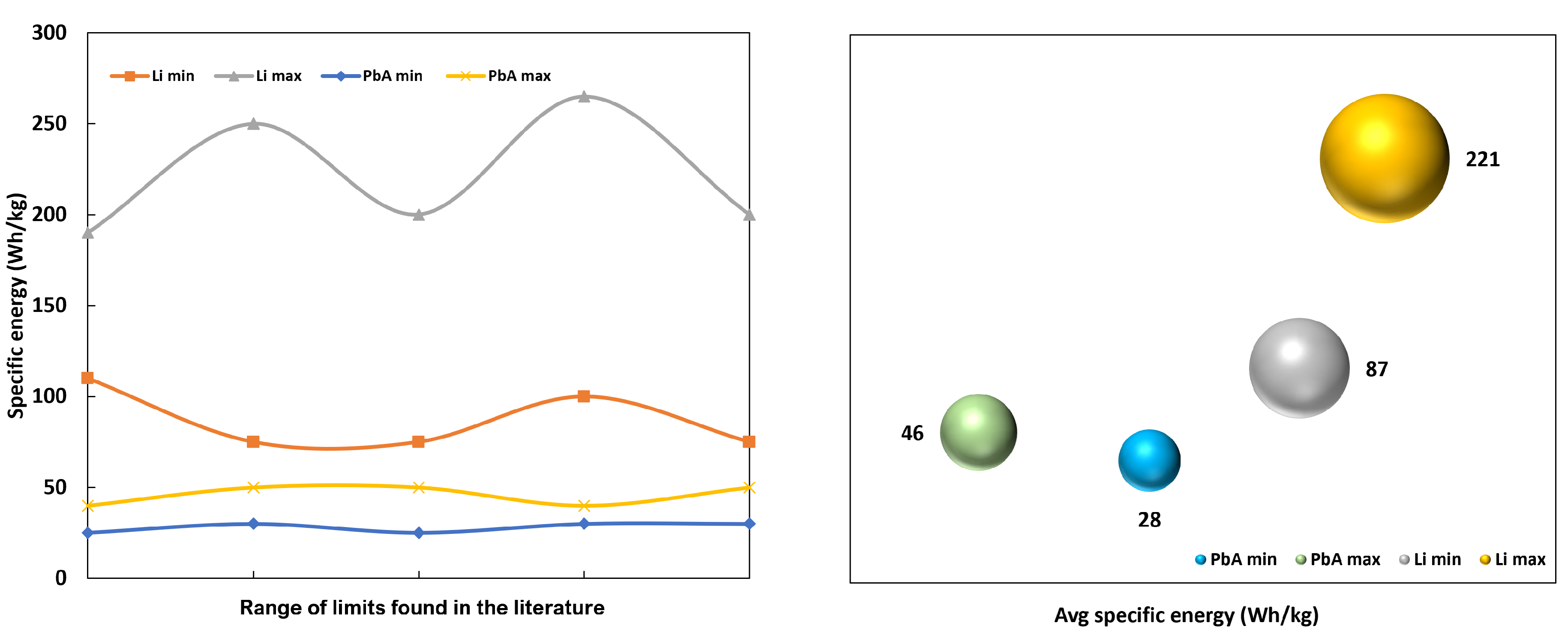
The specific energy values in the table above focus on data obtained from the literature, which are displayed in smoothed curves in
Figure 5 (on the left) for Li-ion and PbA batteries. Thus, the maximum and minimum limits for Li-ion are between 75 Wh/kg and 250 Wh/kg, which is justified because the variation between values is linked to the category of elements that are composing the battery. The rationale for PbA is similar to Li-ion, with its ability to accumulate energy linked to the elements that will interact with lead acid in the battery. The ranges found for PbA are between 25 Wh/kg–50 Wh/kg and the average values for the Li-ion battery are 87 Wh/kg–221 Wh/kg and PbA between 28 Wh/kg–46 Wh/ kg, as shown in
Figure 5 (on the right).
What these specific energy values represent for the development of the HBESS sizing method is the percentage difference in energy between the technologies. When considering the data, it means that lithium-ion batteries have up to four times greater energy density than lead–acid. The HBESS needs its components to be the right size for the applications, especially those that need a lot of energy. The technologies must be equal in density to keep the installation safe and keep costs down.
In this context, this section aimed to present all the concepts involved in the development of the dimensioning method of a hybrid energy storage system using batteries. It is of strong importance to present the characterization of battery technologies, mainly the energy density analysis that underlies the energy compensation method, to be described in
Section 3.
3. Energy Compensation Method—An HBESS Sizing Technique
The research was based on a state-of-the-art survey, with a search in the main databases for works on the HBESS sizing approach. The results showed a low number of publications, in which research on energy management algorithms and on the cost estimation method for HBESS stood out. Furthermore, [
11] presents algorithms that have been demonstrated on a 200 kW test system in the lab, consisting of two categories of lithium-ion batteries: high-power batteries for hybrid vehicles and high-energy batteries for stationary applications. Another outstanding work is on an efficient energy management strategy, proposed for a hybrid vanadium redox battery and lithium-ion battery system to be integrated into a hybrid wind–PV system connected to the grid. The operation of the generation system and storage batteries is evaluated in Matlab/Simulink, and a technical–economic analysis is conducted [
30]. The [
31] article corroborated the topic of topology and control of the HBESS to be developed, since the work deals with an optimization method and control algorithm for HBESS, by combining the high-energy battery with the low-energy battery.
Both the energy capacity that must be distributed among the battery technologies used, and the power capacity, are required by the HBESS. However, the balance of energy capacity between technologies is an unknown parameter among the few sizing methods for battery/battery systems in the literature. As a solution to this problem involving the hybridization between different technologies from the same storage group, such as lead-based and lithium-ion technologies, the developed method is based on the energy compensation between these technologies, which can compose the HBESS.
The research system is composed of two battery technologies. Therefore, their energy density should be the sum between them, similar to the definition of the dual model (HBESS) of [
11] given by the total power of the batteries:
where
represents the power data of the two battery systems and
is the energy of the batteries. Also described by the total energy of the batteries,
, ignores the losses involved in the system when dimensioning. The energy compensation method developed in this article follows the idea of [
32] that defines the nominal energy of a HESS (
) as the battery capacity (
) and supercapacitor energy capacity (
):
There is a hybrid storage system between batteries and supercapacitors. According to the energy compensation method—MCE, the main difference compared with other methods is that the MCE considers losses present in the system and focuses on the energy calculation of a system composed exclusively of batteries. The general HBESS equation is given by:
where,
: low-energy density battery;
: high-energy density battery.
The problem of energy representation of each battery technology in the HBESS was observed. In other words, should the battery with the lowest energy density be considered the smallest part of the system, or should it have a coefficient to equal or increase its participation in the system? This question depends on requirements such as initial cost, operations and maintenance cost, and the necessary autonomy provided by the system. Therefore, there is a need for a coefficient that allows compensation between different technologies, given that some batteries with lower energy density in the market may contain costs lower than the ones with higher density. For example, using a higher amount of NiCd elements and a smaller amount of lithium-ion in an HBESS.
To compensate for the difference in energy density between different types of batteries, a coefficient called the Compensation Factor (
FC) was developed. This factor is defined as the proportion of energy that each technology must have to compensate for its different energy densities. FC is expressed by Equation (
4), where
FC is the factor that represents the share of battery technology with the lowest energy density, and
FC represents the share of high-energy density batteries.
The first step would be to measure the energy capacity (FC) that each category of the battery would need to supply all the needs of the load in question alone, especially regarding the issue of contingency support. This means that sizing a BESS with lithium-ion batteries (E = 75 Wh/kg–250 Wh/kg; 3.7 V–4 V; and depth of discharge is 90%) to supply a given load, compared to a BESS with nickel–cadmium batteries (E = 45 Wh/kg–80 Wh/kg; 1.2 V–1.35 V; and DoD = 90%) to power the same load, results in different energy capacities. The NiCd battery should have at least twice as many cells as the lithium-ion battery to match its energy capacity and supply the same load. This is due to the low-energy density per cell of the NiCd battery.
After calculating the
FC for each battery system separately, it is possible to determine the FC that represents the part of the HBESS with lower-density batteries. Therefore, it must be:
on which,
is the total energy capacity of the system with higher E
battery technologies, considering a single solution;
is the total energy capacity of the system with lower E
battery technologies, considering a single solution.
Using Equation (
4), where
HBESS=1, calculate the part of the HBESS composed of higher energy density batteries. The FC
is obtained by Equation (
6) below:
From the defined ranges for
and
, the HBESS is dimensioned. However, the capacity factor requires sizing the capacity to service the entire load for each chosen technology. The condition imposed on the sizing is:
where E
refers to the load consumption of the installation that will be supplied. Therefore, the energy capacity of a battery, regardless of technology, is calculated based on the maximum energy capacity definition found in [
30]:
where
D represents the autonomy in days and
is the energy required by the load daily (Wh/day), without losses. Based on this definition, the Equation (
8) was developed for the MCE:
in which,
= autonomy time (hours);
= Maximum depth of discharge (%); and
= Energy consumed with loss factor correction (kW), defined by Equation (
9).
where,
is the total daily energy of the loads and
is the factor that represents the losses in the system, calculated by Equation (
10).
The energy capacity of the battery must be adjusted to account for system losses, to supply the loads. This correction considers the minimum losses (
Figure 6), such as the efficiency of the DC/AC converter, which will carry out the process of transforming chemical energy into electrical energy and vice versa; battery self-discharge, which varies according to technology; in addition to other losses that can be evaluated during dimensioning, such as thermal losses and the performance of batteries [
33]. When there is no way to estimate the real value of the battery system, it is estimated that there are 3–10% other losses, depending on the technology.
Thus,
is the factor that represents the losses in the system, described as:
where,
= conversion losses (%);
= battery self-discharge losses (%/day);
= other estimated system losses (%).
Each technologies capacity is defined by Equation (
8), it is possible to return Equations (
5) and (
6) to calculate the compensation factor. From the results of the FC, Equation (
4) is used to find the energy density
and
by applying Equation (
11).
in which,
= autonomy time (hours); and
= maximum depth of discharge (%). The
is the energy with compensation factor correction (kW), defined by Equation (
12).
that is,
is the product of the energy compensation factor found in Equation (
5) and in Equation (
6) by the system loss factor found in Equation (
10).
The calculation process in MCE is summarized and illustrated in
Figure 7.
3.1. Converter Power Sizing for Island Operation
The balance of the microgrid is due to the optimal sizing between the powers of the loads, generation, and storage of energy. The photovoltaic generation has a high penetration, which can cause fluctuations in voltage and reactive power (
Q). Therefore, voltage control of the local microgrid must be implemented. The principle of this control consists of regulating the voltage at the reference limits by regulating
Q in relation to its inductive and capacitive limits [
34,
35,
36]. When transitioning to islanded mode, the difference between load and active power results in a change in frequency indicators. The re-establishment of the reference limits can be solved with HBESS, by applying active power
P to correct the frequency (
f) within the established limits. In the event of an elevation in the frequency, the generation must be reduced until the frequency returns to the appropriate limits. If this solution does not resolve the issue, you must temporarily remove the generation until the frequency returns to the appropriate range. When its reduction occurs, the active power level must be increased on a small scale until normalization around the reference value [
36,
37].
In the results of the original thesis of this article, tests indicated that the HBESS bidirectional DC/AC converter, which operates only connected to the grid, can be dimensioned from the highest apparent power level registered in the load. When specified for an islanded microgrid composed of renewable generation, the PCS must support the variability of PV generation without destabilizing the frequency and voltage reference. However, when the instantaneous active power reduction of the PV plant affects the power quality, the sizing of the HBESS and PV converters should have the same power ratio (1:1 ratio). In the tests, this issue was resolved by reducing the active power of the PV inverter by 30% relative to the PCS. This led to the following consideration to specify the minimum PCS power with a focus on islanded operation:
The sizing depends on the PV power () to be inserted in the microgrid, considering a 30% difference through the coefficient 1.30. The result is true and valid if PCS > P.
It should be noted that, if the HBESS has a topology with two converters, this method will be applied to the converter that will be responsible for forming the islanded microgrid in the presence of renewable generation.
3.2. Statistical Methods Applied to the Results
The validation of the energy compensation method can be performed with the use of software of Hybrid Optimization of Multiple Energy Resources—HOMER Energy. However, it is not possible to simulate the HBESS system in a commercial or project programming environment. In order to simulate each component correctly, each must be simulated separately. Aiming at the reliability of the data resulting from the simulation in commercial software and the MCE, some statistical methods are used to validate the comparative analysis. Thus, the following definitions are provided.
Frequency Distribution—Sturges Rule
The power consumption of some loads is analyzed using a frequency distribution based on the empirical method of Sturges rule. Obtaining the frequency distribution allows us to analyze the distribution of values within a given variation interval, organize and summarize the information numerically. Once the variation interval between
and
to be analyzed is defined, the class size (
) can be calculated, given by [
38]:
where,
K is the number of classes, that is, this variable represents the number of occurrence frequencies that will be counted from a given datum. However, some method or rule must be used to define this value, such as the square root method, or Rices and Sturges rules, the latter being the most suitable for this work. Sturges’ 1926 article published in the Journal of the American Statistical Association is only one page long and presents a normal reference rule, designed to be exact for normal or Gaussian data [
39]. Thence, the Sturges rule is represented by the following class interval:
With the definition of the class interval, it is possible to calculate the amplitude of the classes (h) to be used in the representation of the frequency distribution.
where, the amplitude of the dataset (
L) is found by subtracting the maximum value from the minimum.
3.3. Confidence Intervals
This method of analysis consists of an interval estimate with a certain level of confidence (
1−σ) that allows answering whether among a range of values there is the true value of the population parameter. Decision-making can be done based on the errors found [
40]. The confidence interval is one of the main concepts used in hypothesis tests, used as a measure of uncertainty. Thus, the definition of this method is constructed from [
41]:
: significance level;
: confidence level (98%, 95%, 80%, ...)
n: population sample data;
: mean of the population sample;
: standard deviation.
Thus, the confidence interval for mean
(n > 30) is represented by determining the maximum and minimum confidence limits:
The margin of error for the confidence interval is given by:
4. Case Study: Application of MCE for Microgrid Sizing for Transmission Substation
The case study deals with the application of the MCE to sizing an HBESS that will operate in a microgrid to guarantee a continuous supply of the auxiliary systems of the 230/500 kV substation Teotônio Vilela (SS Messias) in Alagoas, Brazil.
The primary component of the SS Messias microgrid is the HBESS, which provides auxiliary systems to the electrical grid in cases of contingency. When connected to the grid, the energy storage system performs applications such as demand shifting, power factor correction, and PV generation power smoothing.
The microgrid is given by a PV system of 877.03 kWp and power of 700 kW (see
Figure 8), assuming that the photovoltaic power will be 30% below the nominal power of the PCS of the HBESS, in cases of island operation. In addition, there is currently a 225 kVA DG set used as an emergency system, and will remain with this function. However, its control will be executed by the HBESS energy monitoring system, which will have the function of monitoring and controlling the entire microgrid.
The central system of the microgrid is the battery energy storage, which the EMS will communicate with other systems. The solutions operation will depend on the mapped applications:
4.1. HBESS Sizing
For HBESS sizing, it is first necessary to understand the behavior of the load profile of the auxiliary systems of SS Messias, which will be supplied. The power analysis could be performed from the raw data collected in SS.
The active power is observed at the first moment through the statistical analysis of the frequency distribution, based on the empirical method of the Sturges rule. The maximum and minimum values verified are 1.5 pu and 0.297 pu of active power, with a range of classes equal to 11. The result indicates that the highest percentage found of occurrence is 17% of the time with 1 pu of active power, and the lowest occurrence is found above 1.3 pu.
From the statistical analysis of the load data, a typical profile is obtained considering the hourly averages and the frequency of occurrence. Thus,
Figure 9 shows that the typical profile presents a maximum demand of 1 pu at 6 pm and a minimum demand of 0.414 pu at 10 a.m.
Based on the analysis of the substation load, we find the project’s financial resources for purchasing the product, the availability of battery technologies in the Brazilian market, and the use of lead-carbon (manufactured in the country) and lithium ions (sale location available). Thus, HBESS PbC/Li-ion combines the best qualities of each technology to provide optimal performance in all microgrid applications, mainly continuous operation and fulfilling the economic premises of the project.
To determine the appropriate technology choices, information on expected losses was collected using the HBESS dimensioning method. The losses are presented in
Table 3.
Developing Equation (
8) to find the energy capacity that each battery technology needs to supply the load, considering the SS Messias consumption of 2060 kWh/day, the result presents a capacity of
=1,518.27 kWh (PbC) and
= 1,218.79 kWh (Li-ion).
Using the results from Equations (
5) and (
6), the energy compensation factors
and
are obtained to be 0.80 and 0.20, respectively. This indicates that 80% of the energy is carried by the negative frequency components. The total amount of HBESS will be composed of PbC and 20% corresponds to lithium-ion technology. Considering the DoD = 80% for PbC and DoD = 90% for Li-ion, as well as the HBESS autonomy of 12 h. Applying the energy compensation method, Equation (
11), the result of the energy sizing is in
Table 4.
The nominal power of the main PCS of the HBESS (PbC) responsible for the formation of the islanded microgrid is obtained considering the maximum operation of 1.27 pu of the PV plant. Thus, applying Equation (
13) if
, the minimum value found is 1.65 pu. Therefore, the result is true because
, 1.65 pu > 1 pu.
The systems converters have a nominal power of PbC = 2.54 pu and Li = 1.69 pu, following the result of .
4.2. MCE Validation—HOMER Pro
The results obtained from the energy compensation method are validated with simulations in software HOMER Pro, and the response is evaluated using Equation (
8) as the result of the power compensation factor. The main analysis is related to autonomy and behavior during discharge in islanded mode. It should be noted that this software was chosen because it is consolidated and widely used for sizing microgrid elements.
The data provided by software refer to the grid; the load of 2060 kWh/day and 1 pu of peak power; the 1.27 pu PV system; the 1.02 kWh lithium-ion and 1.03 kWh lead-carbon batteries.
Figure 10 presents the results of the nominal capacity of 1,212 kWh PbC and 242 kWh Li-ion, guaranteed autonomy of 12 h of the HBESS in a contingency situation (PbC = 9.6 h and Li-ion = 2.4 h).
In this context, if the fault occurs during the day, photovoltaic generation could supply enough energy to extend the autonomy time up to 14 h.
Figure 11 shows that the HBESS with PbC supplying more than 10 h achieves a performance similar to the baseline. This analysis is performed with the state of charge (SoC) leaving 100% battery life at midnight and extending up to noon. If the fault occurred during the day with greater sun exposure, the probability of increased autonomy would be considerable.
The results of the energy capacity and autonomy presented by HOMER Pro were compared with the results of the energy compensation method, which are shown in
Table 5. It can be seen that there is a high level of similarity between the two sets of results.
The validation result is verified from the statistical analysis with a confidence interval of 95%. The confidence error found in the comparison of sizing data by MCE and HOMER Pro is 1.71 for lithium-ion batteries and 0.372 for PbC, with lower and upper limits that encompass the HBESS values by MCE.
Table 6 shows the detailed results.
4.3. Experimental Validation of the Developed Microgrid
This section presents the tests carried out on an experimental bench in a laboratory with controlled conditions (
Figure 12). The case studies are based on the measurement of the PCS output to evaluate its performance as a grid-forming mechanism. The results are observed from the perspective of HBESS, concerning the stability of the microgrid after the transition to the islanded mode. According to the operation that will take place at SS Messias, the lead–acid system will act as a backup and grid-forming system.
The microgrid test was performed using the HBESS PbC, photovoltaic system, and a load of an electric vehicle. From the beginning of operation until about 10:57:04h, the BESS was in active–reactive power (P-Q) mode and the 1 pu load was powered by the mains. The mains voltage and frequency behavior during this time was characterized by high amplitude peaks and distortion, as shown in
Figure 13.
After
t = 11:21:34h, the PV plant connects to the microgrid, causing a descending ramp in the P
of the HBESS. From time
t = 11:39 onward, the PV generation assumes the load supply and the HBESS only fulfills the role of grid-forming. The frequency follows the behavior of the P
of the microgrid, with values close to 1 pu. Even with the variations in solar power seen in
Figure 14, the local grid maintains a frequency on the scale of 0.99 pu.
It is observed in
Figure 15 that the oscillations attenuate after the transition, stabilizing between 1 pu and 1.015 pu. The PV generation variation that affects P
has negligible impacts on the voltage, and therefore does not affect the stability of the local grid or the PQ indices.
After the contingency, the HBESS acts to ensure that the imbalance related to generation and demand is met without causing disturbances in voltage and frequency.
Figure 16 (on the right) shows the frequency behavior. If a fault is detected at time 0 s, then the frequency will drop, and the BESS will observe this action as an increase in load. In response, the BESS will inject active power at a time 1 s, in an attempt to stabilize the microgrid before a power outage occurs. The load will experience a lack of main power if this action is not successful. When faced with this scenario, the voltage behavior is shown in
Figure 16 on the left, where the influence of reactive power at
t = 0 s with the input of the energy storage system is observed. This keeps the stability close to 1 pu.
When evaluating the data from the tests with the Brazilian Standard (Electric Power Distribution Procedures in the National Electric System – PRODIST) reference values at steady state (
Table 7), it was found that the two case studies maintained the values of their operations within the limits. This was the case for voltage and the frequency in 1 pu, in both cases. The microgrid voltage level did not allow performing an analysis with the ONS standard, in addition, the voltage unbalances and the total harmonic distortion (THD
) remained at the appropriate percentage.
The tests affirmed the validation of the methodology used for the development of the HBESS, demonstrating the stability of the islanded microgrid and the reliability of the system in a contingency situation.
5. Conclusions
This article presented the HBESS sizing methodology through the development of the Energy Compensation Method for applications in microgrids. The study examined the energy density that each chemical element carries in its structure, as well as the electrochemical cell that can be composed of one or more elements. The specific energy difference between two battery technologies makes it possible to determine which compensation factor should be adopted for each technology. The methodology was validated by comparing the results from HOMER Pro with experimental results from bench tests.
The MCE is applied for the design of an energetically reliable solution, using a hybrid battery energy storage system and the photovoltaic system as an internal autonomous source for the auxiliary systems of the 230/500 kV Teotônio Vilela substation (Messias SS) in Alagoas, Brazil. With this case study, it was possible to verify the applicability of the methodology, resulting in the development of the HBESS of 1215 kWh/300 kW PbC and 242 kWh/200 kW Li-ion. The choice of these two technologies is because each battery has different characteristics aimed at power and energy applications. It is emphasized that the two technologies can meet all SE applications, but that each one has its greatest optimization and performance in certain functions. Through a correlation of the characteristics of the batteries and the applications, it was observed that the HBESS solution is the most compatible to meet the demand of a load that performs great responsibility and strategy in some sectors. The combination of the two technologies, therefore, promotes not only performance but also security, due to the presence of two PCS—one for each technology. This guarantees sufficient autonomy for contingency situations, which must be supplied primarily by the PbC. Furthermore, the study was conducted under laboratory conditions similar to the islanded mode of operation of the microgrid with composition and operation similar to the system developed for SS Messias. It is observed that the influence of the HBESS of PbC has a positive impact on the maintenance and improvement of the electric energy quality indicators. There are no variations in frequency and voltage within the limits of the reference indicators, with no disturbances, that would allow the characterization of sags or swells. Thus, the test results correspond to the operating principle adopted for the islanded microgrid, respecting the ratio of photovoltaic generation and energy storage in the proportion of 0.7:1, respectively.
Recommendations for future research include the application of the method in case studies with battery technologies besides lead–acid and lithium-ion. In addition, the MCE has as a limitation with the application in islanded microgrids. It is suggested to study the relationship between the connected applications and the developed method. Another point is research into replacing the diesel generator as the main source of uninterrupted supply. Instead, there will be the insertion of the exclusive use of microgrids with energy storage systems by batteries and a photovoltaic plant as an autonomous source to supply the auxiliary systems of transmission substations.


 ,
, 


