Article

Preparation and Characterization of n-Octadecane@SiO2/GO and n-Octadecane@SiO2/Ag Nanoencapsulated Phase Change Material for Immersion Cooling of Li-Ion Battery

1
Institute for Clean Energy Technology, North China Electric Power University, Beijing 102206, China
2
Thermal Process Engineering, Otto von Guericke University, 39106 Magdebur, Germany
3
Beijing Key Laboratory of Emission Surveillance and Control for Thermal Power Generation, North China Electric Power University, Beijing 102206, China
4
MOE Key Laboratory of Power Station Energy Transfer Conversion and System, North China Electric Power University, Beijing 102206, China
*
Author to whom correspondence should be addressed.
Energies 2023, 16(3), 1498; https://doi.org/10.3390/en16031498
Submission received: 7 January 2023 / Revised: 28 January 2023 / Accepted: 1 February 2023 / Published: 2 February 2023
(This article belongs to the Special Issue Heat and Cold Storage for a Net-Zero Future)

Abstract

:
Nanoencapsulated phase change materials (NePCMs) are promising thermal energy storage (TES) and heat transfer materials that show great potential in battery thermal management systems (BTMSs). In this work, nanocapsules with a paraffin core and silica shell were prepared using an optimized sol-gel method. The samples were characterized by different methods regarding chemical composition, thermal properties, etc. Then, the nanocapsules were used as the coolant by mixing with insulation oil in the immersion cooling of a simulative battery. The sample doped with Ag on the shell with a core-to-shell ratio of 1:1 showed the best performance. Compared to the sample without doping material, the thermal conductivity increased by 49%, while the supercooling degree was reduced by 35.6%. The average temperature of the simulative battery cooled by nanocapsule slurries decreased by up to 3.95 °C compared to the test performed with pure insulation oil as the coolant. These novel nanocapsules show great potential in the immersion cooling of a battery.

Graphical Abstract

1. Introduction

To meet the growing energy demand, the development of renewable energy is essential and increasingly important. The volatility and intermittency of renewable energy resources, such as wind energy and photovoltaics, limit their wide application [1], and therefore, energy storage technology (EST) is required [2]. There are various types of energy storage methods [3], with the major types categorized as electrochemical and battery energy storage, flywheel energy storage, compressed air energy storage, etc. Electrochemical energy storage systems based on the Li-ion battery are one of the most promising ESTs due to their flexibility, high energy densities, and long life span [4]. The optimal operating temperature of batteries is 25–50 °C [5,6]. However, heat generation is inevitable during charging and discharging [4,5,6,7,8,9,10,11]. The main methods used for the battery thermal management system (BTMS) are air cooling and heating [9], liquid cooling and heating [10], phase change material (PCM) cooling and heating [11], etc. Among them, PCMs [12,13] are important latent heat storage materials with high energy storage efficiency [14], and they have the property of maintaining an almost constant temperature [15,16] during heat storage and release. Huang et al. [11] proposed a method for the thermal management of Li-ion battery packs with the application of various flexible, form-stable composite phase change materials (CPCMs). However, the heat accumulation in PCMs caused by inefficient air cooling and heating still limits their application [17]. Park et al. [18] found that mineral oil cooling reduced pumping costs by around 50% as compared to air cooling by numerically studying different cooling methods in BTMS. Qaderi et al. [19] designed a PCM-based BTMS integrated with water-nanoencapsulated phase change material (water-NePCM). Compared to water, water-NePCM can reduce the average and maximum temperatures of the battery by up to 34% and 51%, respectively. Ling et al. [17] developed a hybrid system that integrated PCMs with forced air convection. The results show that the maximum temperature difference in the hybrid thermal management system was less than 3 °C. It is worth mentioning that the cold plates and battery outer surfaces, as a method of indirect cooling, must be adequately thermally bonded to reduce the thermal contact resistance [20]. This leads to high costs due to the requirement of precision cold plates and the application of thermal grease or epoxy bonding agents to remove air gaps [21]. Therefore, the hybrid system based on direct cooling is an ideal choice. Immersion cooling technology, as a type of direct cooling, has a higher heat transfer efficiency and simpler design because it does not rely on a secondary or indirect way of cooling the system [20]. Due to these advantages, researchers have put forward more and more ideas for using the immersion method, for example, in solar cells [22], computers and other electronics [23], and batteries [21,24]. Patil et al. [21] investigated the immersion cooling performance of a Li-ion battery and battery pack for electric vehicles with dielectric fluid. Their experimental results showed that the Li-ion pouch cell immersed in flowing dielectric fluid and assisted with tab cooling showed better cooling performance, and the maximum temperature at the positive tab decreased by 46.8% compared to natural convection at a 3 °C discharge rate. Meanwhile, the thermal runaway of a battery pack was prevented, except for the affected cell under the thermal abuse condition with an internal short circuit. Trimbake et al. [24] reported the experimental results of the Li-ion pack immersed in mineral oil with oil jet impingement. Based on their results, immersion cooling has excellent performance for the cooling of Li-ion packs and is applicable to stationary electrical storage and transportation applications.
By mixing PCMs with oil, the oil acts as a heat transfer fluid that allows the heat energy to be easily transported. However, there are some challenges to utilizing PCMs in the immersion cooling of batteries. For example, the leakage [25,26] of PCMs during the phase change process and low thermal conductivity have limited their application [27]. The use of microencapsulation technology can encapsulate PCMs into tiny containers to make micro- or nanophase change capsules [28,29,30], which can prevent leakage during melting and improve heat transfer efficiency [30] by increasing the specific surface area. Meanwhile, the thermal conductivity of PCMs can be effectively improved by using composite shell materials with a high thermal conductivity [31]. The widely used encapsulation methods mainly include the sol-gel process, interfacial polymerization, and in-situ polymerization [32]. The number of available investigations on encapsulated PCMs is relatively high. Some of the previous work is summarized in Table 1. In the work conducted by Jiang et al. [33], the synthesized microcapsules showed good thermal storage capability and high thermal reliability but still suffered from supercooling. Do et al. [34] loaded Cu metal nanoparticles on the outer wall of the capsule, which increased the heat transfer ability and thermal reliability significantly. By adding graphene, the thermal conductivity of the nanocapsules increased by 132.9% [35]. As a type of carbon-based material, GO [36,37] has extraordinary electrical, thermal, and mechanical properties, while its unique layered structure gives it a high surface area. It has been widely used in many fields, such as batteries, energy storage, sensors, etc. As a high thermal conductivity material, the composite capsule prepared by GO can greatly improve the thermal conductivity and optimize the capsule properties, as shown in the work conducted by Zhang et al. [38], Gao et al. [28], He et al. [39], and Li et al. [40]. Compared to MePCMs (a particle size of 1–1000 μm), NePCMs (a particle size less than 1 μm) have a higher specific surface area, which facilitates the heat transfer rate [27]. In addition, NePCMs are mechanically more stable [41,42] during operation. Although much progress has been made in the previous works, the practical application of the NePCMs in the immersion of batteries still faces some challenges, such as the suppression of supercooling behavior [43], an unsuitable melting point [39], low thermal conductivity [28], and a low heat of fusion [35]. A new NePCM that can overcome these drawbacks and is designed for the immersion cooling of batteries is desirable.
In the current work, we innovatively applied the NePCMs as the coolant in the immersion cooling of batteries by mixing them with insulation oil. These nanocapsules were synthesized using an optimized sol-gel method with paraffin as the core material and silica as the shell material. The core-to-shell ratios and concentrations of emulsifier were varied in the experiments. To further improve the thermal conductivity of nanocapsules, GO and Ag were doped into both the core and wall materials, which enabled the capsule shell to provide nucleation sites for PCMs to reduce their supercooling degree by optimizing the capsule structure. The synthesized nanocapsules were characterized by different methods in terms of chemical composition, morphology, microstructure, phase change properties, thermal conductivity, and stability. To use the nanocapsules in the immersion cooling of a battery, some of the nanocapsules were mixed with insulation oil to form slurries. The slurries were employed as the coolant in the immersion cooling experiments to test their performance by measuring the temperature change of a simulative battery.

2. Materials and Methods

2.1. Materials

n-Octadecane (n-OD, 99 wt%), Tetraethyl orthosilicate (TEOS), anhydrous ethanol, and NH3·H2O (25–28 wt%) were purchased from Macklin Chemical Reagents. Cetyltrimethylammonium bromide (CTAB) and sodium dodecyl sulfate (SDS) were provided by Sinopharm Chemical Reagents, while GO dispersion water (2 mg/mL) and Nano-Silver (Ag) (99.9 wt%) were provided by Nanjing XFNano Material Tech. Transformer oil No.40 was bought from Dongguan Luosheng Lubricant. Deionized water was homemade in the laboratory. All reagents were of analytical grade and used as received without further purification.

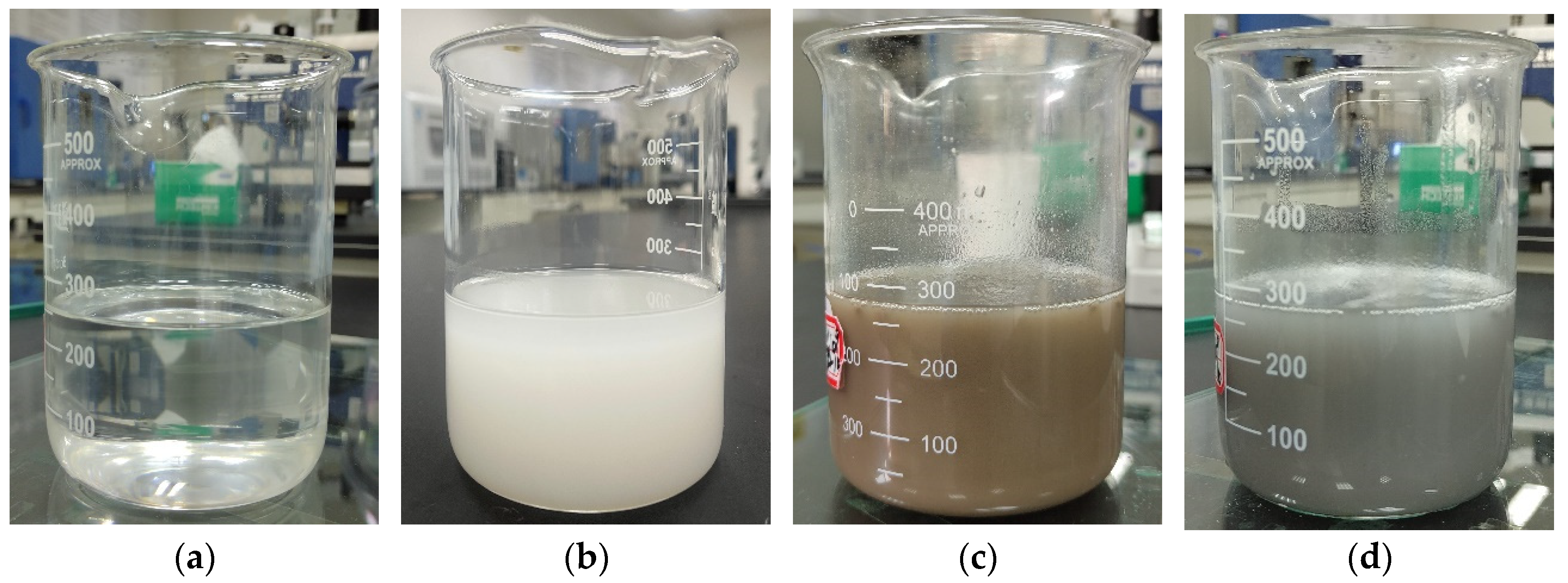
2.2. Preparation of Nanocapsules

As shown in Table 2, the experiments for the preparation of nanocapsules are divided into two series. In the first series, S1–S4 were synthesized with varied core-to-shell mass ratios, and S5 with varied concentrations of emulsifier. In the second series, S6 and S7 were core-doped nanomaterials, and S8 and S9 were wall-doped nanomaterials.
The scheme for the preparation process is shown in Figure 1. First, certain amounts of n-octadecane and CTAB, as well as deionized water (27 mL) and anhydrous ethanol (90 mL), were added to a 250 mL beaker and mixed. For S6 and S7, before the addition of CTAB, deionized water, and anhydrous ethanol, n-octadecane was mixed with a certain amount of GO water dispersion or Ag and ultrasonically agitated for 30 min. Afterwards, the mixture was emulsified at 10,000 rpm for 20 min and sonicated for 10 min. After that, the mixture was transferred to a three-necked flask (250 mL) and thermostated in the water bath at 35 °C. At the same time, TEOS (10 mL) and SDS (0.4 g) were added into a 100 mL beaker, and the mixture was ultrasonically agitated at a constant temperature of 35 °C for 10 min; then it was added to the three-necked flask drop by drop with gentle stirring at 500 rpm for 2 h. After that, 2 mL of ammonia was added dropwise to the flask. For S8 and S9, a certain amount of GO water dispersion or Ag was added into the three-necked flask with gentle stirring at 500 rpm after the addition of ammonia. The mixture was stirred for 21 h. Finally, the mixture was filtered, washed three times with anhydrous ethanol, and air-dried at 60 °C for 24 h to obtain the products.

2.3. Characterization

The chemical structure and composition of the samples were characterized using Fourier transform infrared spectroscopy (FTIR, Vertex 80v, Bruker, Germany) in the range of 600 cm−1–4000 cm−1 with a KBr sampling sheet. The Raman spectra were analyzed by a Raman spectrometer (Raman, Senterra, Bruker, Germany) with a radiation source of λ = 532 nm and a wavenumber range of 500–2000 cm−1. The surface elemental distribution was characterized by X-ray photoelectron (XPS) spectroscopy (VG ESCALAB 250). The crystal structure was determined by powder X-ray diffraction (XRD, D8 Advance diffractometer, Bruker, Germany) with Cu Kα radiation (λ = 0.154 nm), at 2θ range of 10–80° and a scanning rate of 10 °/min.
The morphology and microstructure of the samples were determined by transmission electron microscopy (TEM, H-800, Hitachi, Japan) and scanning electron microscopy (SEM, S-4800, Hitachi, Japan). Before the observation, the specimens were coated with a thin layer of gold. Based on the obtained SEM micrographs, the particle size distributions of the nanocapsules were determined using NanoMeasurer 1.2.
The thermal property was characterized by a differential scanning calorimeter (DSC, Q2000, TA Instruments, USA) at a heating or cooling rate of 5 °C/min, in the range of 0–50 °C, under N2 conditions. The phase-change properties of the samples were calculated using TA Universal Analysis 2000. Thermal conductivity was measured by a laser thermal conductivity testing instrument (LFA1000, Linseis, Germany) at room temperature (20 °C). The thermal stability was characterized by a thermal gravimetric analyzer (TGA, Q600, TA Instruments, New Castle, DE, USA) in a nitrogen atmosphere, and the temperature range was from 25 °C to 550 °C.

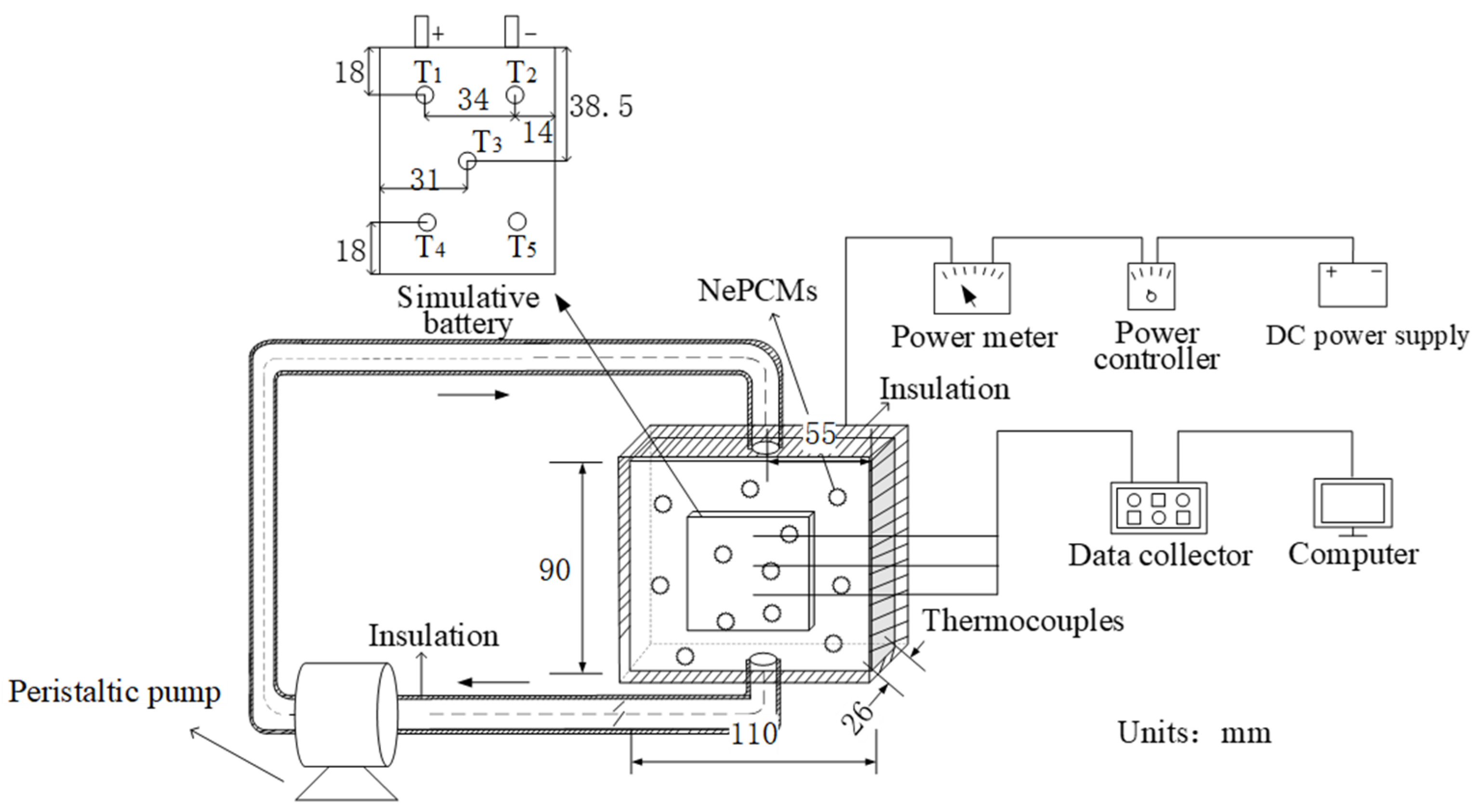
2.4. BTMS Experiment

To evaluate the temperature control effect of the nanocapsules in a BTMS, a set of battery thermal management experimental devices were tailored, which were composed of a compact test rig, a simulative battery, a peristaltic pump, foam insulation materials, thermocouples, a power meter, a power controller, a DC power supply, a computer, and a data collector (HIOKI LR8431CN), as shown in Figure 2. Instead of using a real battery, a heating panel was used as a simulative battery in our experiment, which had the same dimensions as a 4.5 Ah battery (77 × 62 × 15 mm, produced by Fujian Super Power New Energy Co., Ltd., Fujian, China). Compared to the real battery, the simulative battery is safer and easier to control, and it also enables the study to operate under conditions that cannot be achieved by real batteries [11]. The thermal power of the battery was about 6 W and 26 W at 3 °C and 5 °C discharge rates, respectively, which were calculated based on the model developed in the previous work [44]. Therefore, the power of the heating panel was controlled at 6 W and 26 W using the power controller. To measure the temperature of the simulative battery, five thermocouples (denoted T1–T5) were placed at different positions. The simulative battery was placed in a container. To minimize heat loss, the container and pipes were sealed with insulation materials.

3. Results and Discussion

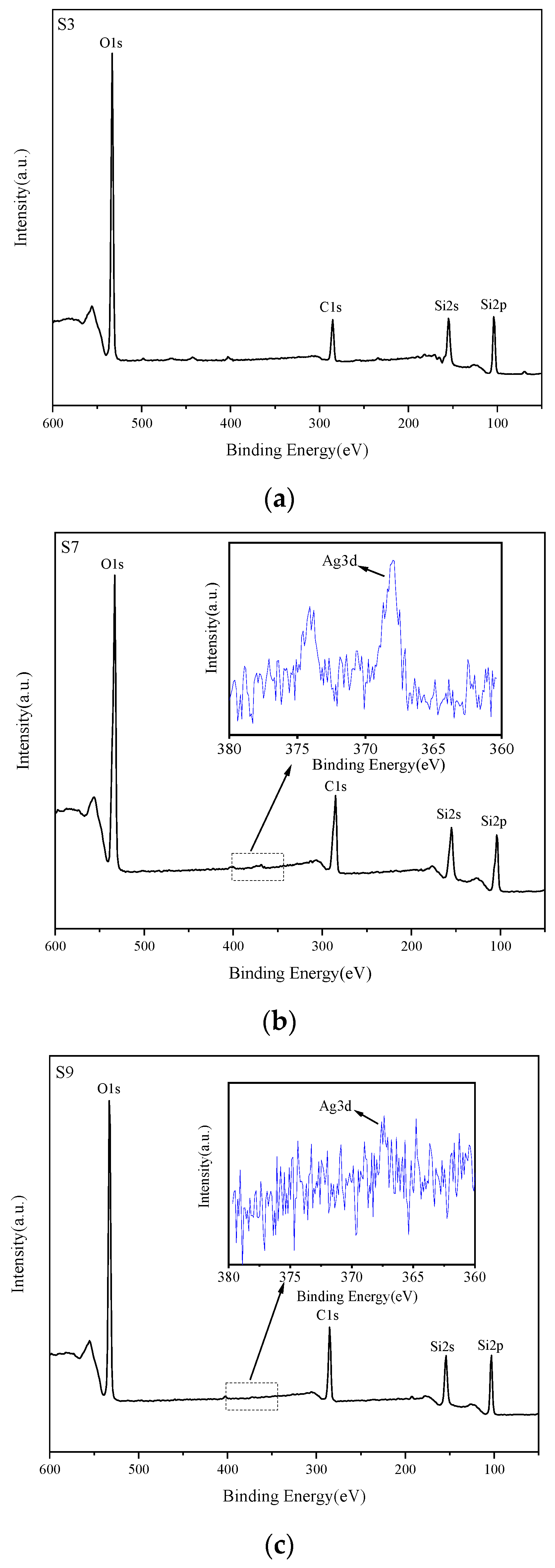
3.1. Chemical Composition and Crystal Structure

The infrared spectra of pristine n-octadecane and nanocapsules are shown in Figure 3. The characteristic absorption peaks of n-octadecane were 2924 cm−1, 2855 cm−1, 1465 cm−1, and 719 cm−1, where 719 cm−1 is the rocking vibration of -CH2, 1465 cm−1 is the deformation vibration of -CH2, and the stretching vibration [45] of -CH2 and -CH3 are 2924 cm−1 and 2855 cm−1, respectively. The characteristic absorption peaks of silica are 3428 cm−1, 1080 cm−1, 950 cm−1, and 798 cm−1. Among them, the absorption peaks at 1080 cm−1 and 798 cm−1 are caused by the asymmetric and symmetric stretching band vibrations of Si-O-Si [46]. All the characteristic absorption peaks of n-octadecane and silica can be clearly observed in Figure 3. Furthermore, no new characteristic absorption peak is observed, indicating that the silica and n-octadecane interact physically rather than chemically. However, absorption peaks of doped GO and Ag are not found in S6–S9. Therefore, Raman testing was conducted to confirm the existence of GO for S6 and S8 [28]. Metallic Ag does not have an absorption peak in the range of 600 cm−1–4000 cm−1; thus, S7 and S9 were characterized using XPS [47].
To prove the existence of GO, the S3, S6, and S8 were measured by Raman, and the results are presented in Figure 4. Compared to S3 without GO, both S6 doped with GO in the capsule core material and S8 doped with GO in the capsule wall material have obvious characteristic absorption peaks at 1356 cm−1 and 1601 cm−1, which are named (D) band and (G) band, respectively [48]. The D peak represents the disorder and structural defects on the carbon network of graphene, and the G peak is related to the scattering of the E2g phonon of sp2 carbon atoms [49], which provides evidence for the successful introduction of GO in S6 and S8.
To prove the existence of Ag, the S3, S7, and S9 were measured by XPS characterization, and the results are presented in Figure 5. As can be seen, Si, C, and O elements are obviously included in S3. After the core and wall materials have been doped with Ag, the XPS spectra of S7 and S9 show the characteristic peaks of Ag3d [47], specifically, Ag 3d3/2 at 374 eV and Ag 3d5/2 at 368 eV, respectively, demonstrating the existence of Ag [50].
XRD was used to analyze the crystal structure of n-octadecane and nanocapsules. As shown in Figure 6, n-octadecane exhibits a thermodynamically stable triclinic phase with characteristic absorption peaks of 2θ = 19.26°, 19.78°, 23.3°, and 24.7° [35]. Meanwhile, all the prepared nanocapsules contain all the diffraction peaks of n-octadecane, and no other new diffraction peaks appear. A broad peak in the range of 2θ = 16–30° is attributed to the amorphous SiO2 in the capsule wall material, which indicates that there are only physical interactions in these nanocapsules and that the crystalline structures of the nanocapsules are not changed by encapsulation. Meanwhile, it can be found that the spectra of S6 and S8 doped with GO show stronger absorption than S3 in the range of 2θ = 16–30°, which is due to the existence of GO [51] and SiO2. Diffraction peaks of metallic Ag can be found in the spectra of Ag-doped S7 and S9, which are located at 2θ = 38.1°, 44.3°, 64.5°, and 77.5° [47], respectively. The XRD results are consistent with the aforementioned results and further confirm that GO and Ag have been successfully doped in the corresponding nanocapsules.

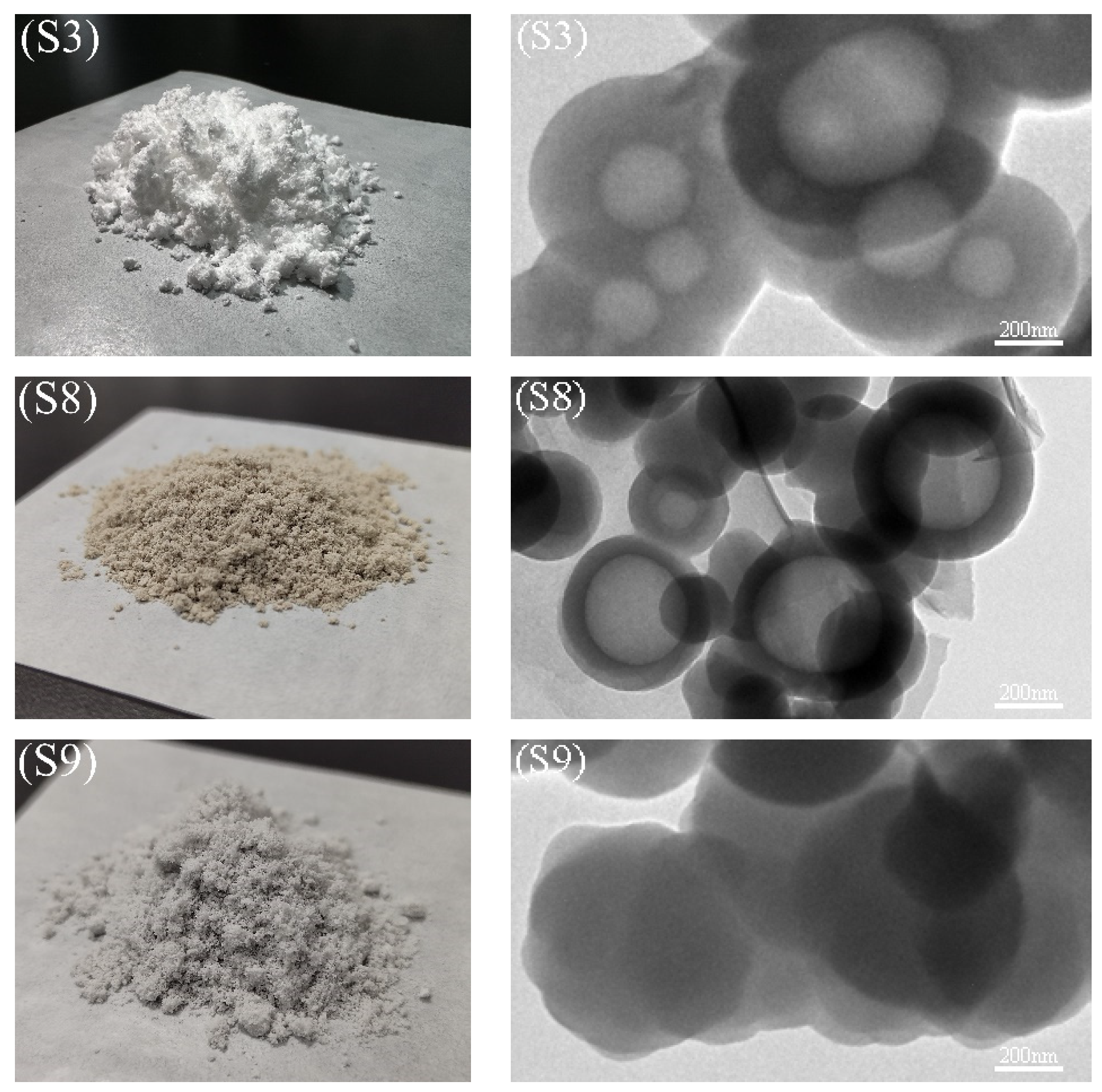
3.2. Morphology and Microstructure

The morphology of the nanocapsules was analyzed by scanning electron microscopy (SEM), and the results are shown in Figure 7. In the figures, the surface of S1 is relatively rough with many attachments, which are caused by the accumulation of excess silica on the capsule surface due to its low core-shell ratio. When the core-shell ratio is increased to 1:1, the obtained S3 samples are white particles with a regular spherical shape and have a relatively smooth surface. However, when the core-shell ratio is further increased to 4:3, broken spherical shells are found, which can be attributed to the secondary hydrolysis of silanol [52]. A lot of attachments on the surface of S5 nanocapsules are observed, and the nanocapsules show severe aggregations because the emulsifier content of S5 was halved compared to that of S3. Therefore, it indicates that the core-shell ratio and the concentration of emulsifier have significant influences on the capsule morphology and aggregation during preparation.
To improve the thermal conductivity of the capsules, GO and Ag were added to the core materials of S6 and S7, respectively. Compared to S3, the surface of the nanocapsules is rougher, and the nanocapsules aggregate massively. The nanocapsules from S7 show broken spherical shells, which means that the formation of nanocapsules may be interrupted by the core-doped nanomaterials in the preparation stage. The same proportion of GO and Ag was doped in the wall materials of S8 and S9, respectively. In previous characterizations, it was found that GO has been successfully embedded in the surface of the nanocapsules for S8 and that the shape of the nanocapsules is not regular due to the addition of nanomaterials. Tzou [53,54] found that highly promoted turbulence caused by the incorporation of nanoparticles increased the energy-bearing capacity of nanofluids, potentially leading to a higher overall heat transfer coefficient than an increase in effective thermal conductivity alone. Therefore, the latent heat functional fluid prepared by using modified nanocapsules can improve heat transfer efficiency. Similar to S8, the Ag doped in S9 has been successfully attached to the surface of the nanocapsules.
S3, S8, and S9 are in a regular spherical shape, as shown in the SEM analysis, and they were characterized further by TEM. Their photographs and TEM images are shown in Figure 8, and the particle size distribution is shown in Figure 9. S3 are white particles with a distinct core-shell structure and an average particle size of 0.55 μm, as seen in Figure 8 and Figure 9. S8 particles are brown in color and have a clear core-shell structure with GO flakes attached to the capsule surface after the wall material has been embedded with GO, and the average particle size is reduced to 0.42 μm. The color of S9 particles is gray after the wall material has been embedded with Ag. There are Ag particles attached on the surface of the capsule, while the average particle size is reduced to 0.28 μm, which is due to the effect of the added nanomaterials stabilizing the emulsion [33]. Again, the TEM results prove that GO and Ag have been successfully introduced in S8 and S9, respectively.

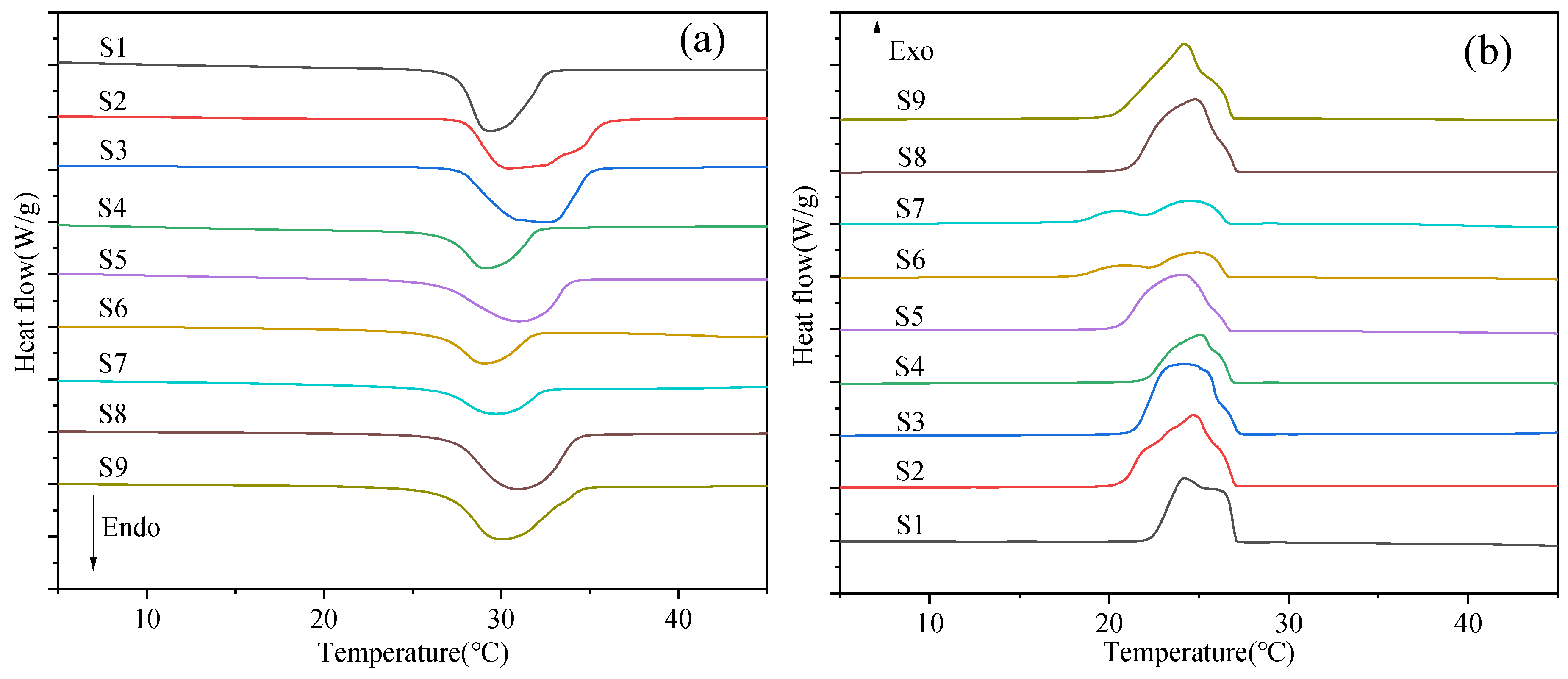
3.3. Phase Change Properties

The phase-transition properties of the prepared nanocapsules were characterized by DSC. The melting and crystallization curves are shown in Figure 10. Meanwhile, phase change temperatures and enthalpies of the nanocapsules are detailed in Table 3. As seen in Figure 10a, there is only one exothermic peak existing in the melting process of S1–S5, which is ascribed to the triclinic-liquid phase transition of n-OD [47,55]. Meanwhile, according to the data in Table 3, the enthalpy of S1–S5 increases and then decreases with the rise of the core-shell ratio and reaches its maximum at a core-shell ratio of 1:1 with a value of 126.4 J/g. The enthalpy of S5 decreased by 23% compared to that of S3 due to the halving of the emulsifier concentration. The melting process of S6 and S7 is similar to that of S3, with only one heat absorption peak. However, the crystallization process has multiple exothermic peaks, and the supercooling degree has further increased.
As shown in Table 3, the enthalpy of S6 and S7 is 56.7% and 60.2% lower than that of S3, respectively, indicating that the prepared nanocapsules need to be further optimized, which is consistent with the results obtained from SEM analysis. The melting and crystallization processes of S8 and S9 are the same as those of S3 after adding the same proportions of GO and Ag to their wall materials, and there is only one exothermic peak in both the melting and crystallization processes. Compared to S3, the enthalpy of S8 and S9 is not significantly reduced, but the supercooling degree is reduced by 31.7% and 35.6%, respectively, due to the addition of high thermal conductivity nanomaterials.
GO and Ag in the capsule shells optimize the shell structure and composition to induce homogeneous nucleation without the addition of nucleating agents, thereby reducing supercooling [43,56]. It is highlighted that S3 has the highest enthalpy of 126.4 J/g with an appropriate emulsifier concentration and core-shell ratio of 1:1 in all the prepared nanocapsules. The supercooling degree of S8 and S9 decreased significantly, but they still maintained a high enthalpy after the wall materials were doped with GO and Ag.

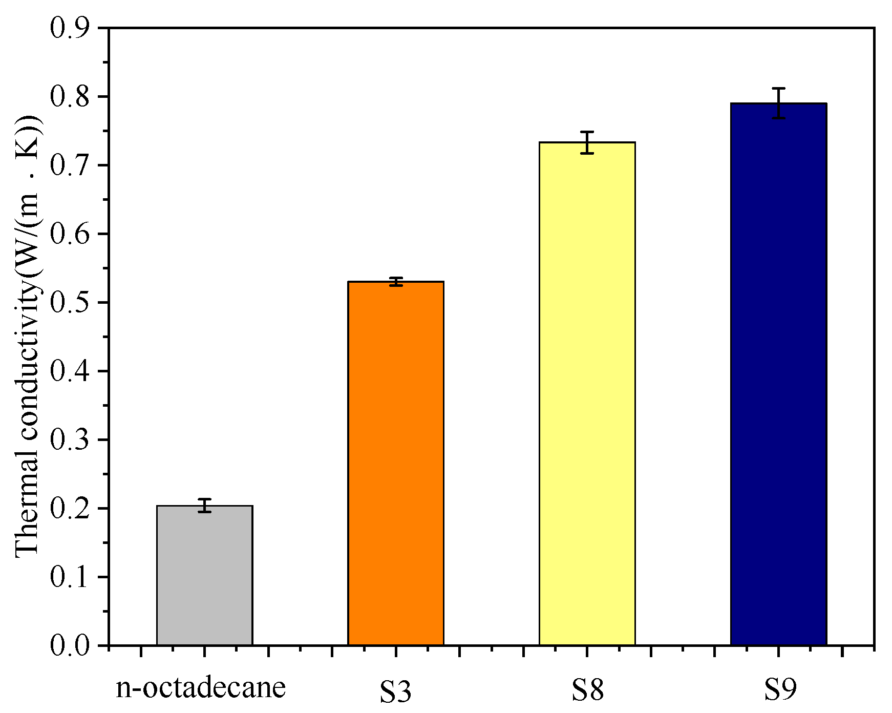
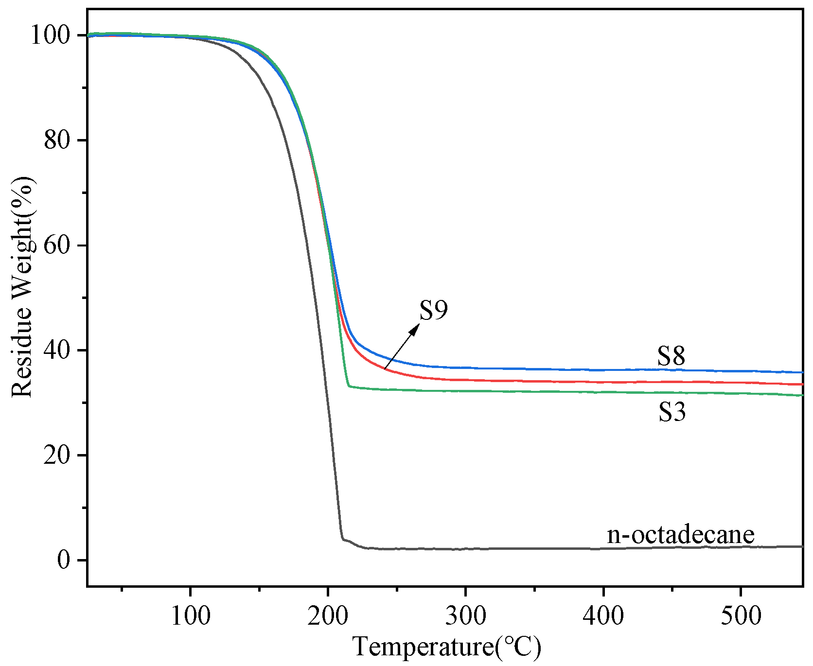
3.4. Thermal Conductivity and Thermal Stability of the Nanocapsules
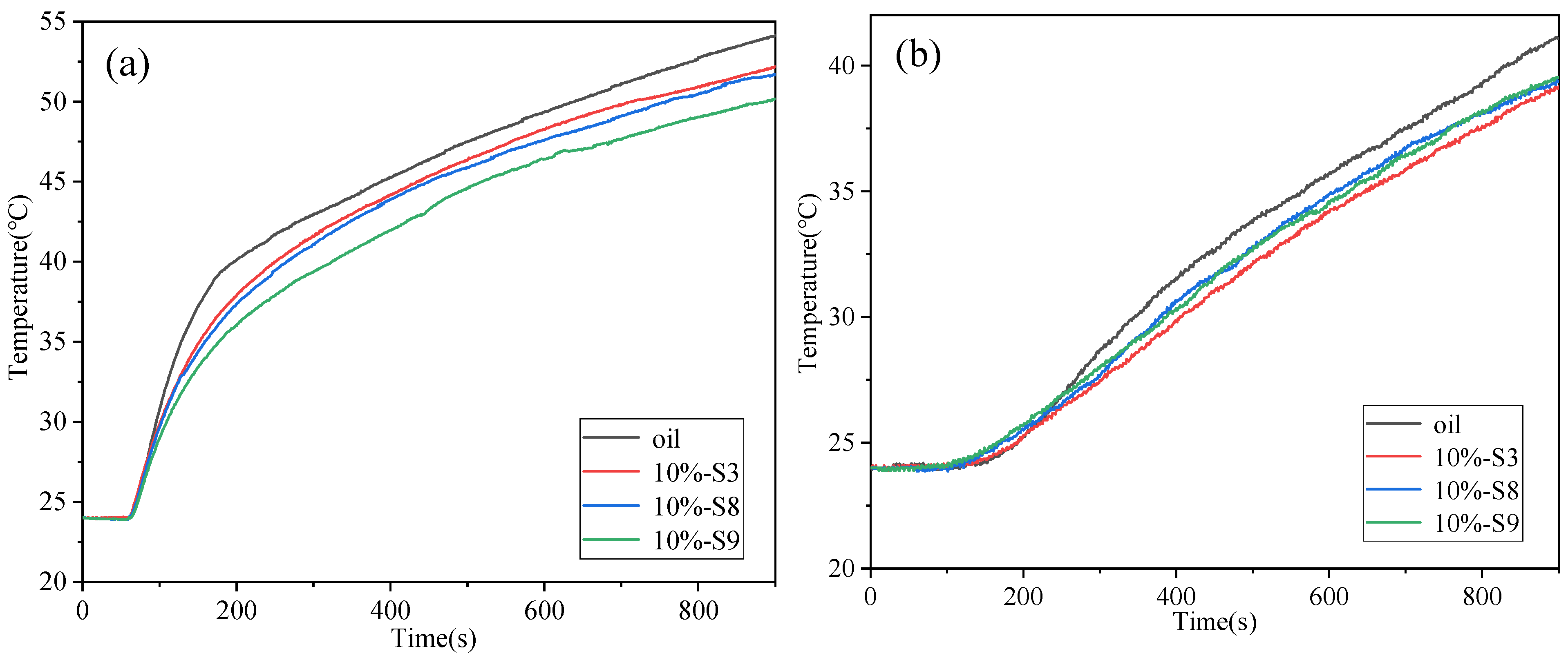
The thermal conductivity of n-octadecane, S3, S8, and S9 is shown in Figure 11. The thermal conductivity of n-octadecane is 0.2042 W/(m∙K), while the thermal conductivity of S3 (silica-coated n-octadecane) is 0.5304 W/(m∙K), which increased by 259.7%. Compared to S3, the thermal conductivity of S8 doped with GO further increased by 38.3% to 0.7333 W/(m∙K), and that of S9 doped with Ag increased by 49% to 0.7903 W/(m∙K).
As shown by the TGA curve in Figure 12, the initial weight loss (5% mass weight) temperature of n-octadecane is 141 °C, and its complete weight loss temperature is 228 °C. After encapsulation, the initial weight loss temperature of S3 increased from 18 °C to 159 °C, which indicates that the heat resistance of n-octadecane has been improved through the encapsulation by the silica shell. After further doping with GO and Ag (S8 and S9), its thermal stability did not change significantly.
In summary, the prepared nanocapsules were characterized in terms of chemical composition, microstructure, morphology, thermal properties, and thermal conductivity. It has been found that when the core-shell ratio is 1:1, the obtained S3 samples are white particles with a regular spherical shape, distinct core-shell structure, high enthalpy, high thermal conductivity, and excellent thermal stability. Furthermore, GO and Ag were doped in both the core and shell materials with optimized parameters (the same as S3). Compared to S3, the thermal conductivity of S8 (doped with GO on the shell) and S9 (doped with Ag on the shell) increased by 38.3% and 49%, while the supercooling degree was reduced by 31.7% and 35.6%, respectively. Meanwhile, S8 and S9 possessed a narrow phase transition temperature range, maintained high enthalpy, and improved in thermal stability. Overall, S3, S8, and S9 can be good candidates for efficient thermal control in the field of BTMS. These three samples were further used in BTMS with a simulative battery.

4. BTMS Test

In order to test the temperature control of nanocapsules in BTMS, the nanocapsules of S3, S8, and S9 were mixed with insulation oil with a mass fraction of 10% by ultrasonication to form slurries. The slurries obtained not only avoided the safety hazards such as short circuits and leakage but also improved the specific heat capacity and thermal conductivity [57] due to the addition of nanocapsules. Pictures of the untreated insulation oil and the slurries with different nanocapsules are shown in Figure 13. The nanocapsules in the prepared slurry diffuse steadily and do not show severe aggregation. First, the simulative battery was placed vertically in a container with insulation materials, and then 235 g of the slurry was added to the container. After that, the simulative battery was completely immersed. The ambient temperature was kept constant at 24 °C. The flow rate of the peristaltic pump was kept at about 820 mL/min, and the input power of the heating panel was controlled by a power controller. The initial temperature of the system was 24 °C, and the total test time was set to 900 s. After starting the experiment, the first 60 s were the preparation period. During this period, all test devices were switched on except the simulative battery. This period was used to achieve stable system operation and eliminate adverse effects on the test results. After that, the simulative battery was powered up. In order to reduce the temperature error, the average value of the data obtained from all five thermocouples was used.
The slurry temperature of the test with thermal power at 3 C was too low to reach the critical phase transition temperature of the nanocapsules; thus, the results are not shown in this work. Figure 14 presents the temperature change curve of the simulative battery and slurry under 26 W with time. The phase change onset temperature of the nanocapsules is about 25 °C, according to the DSC curve. As shown in Figure 14a, the temperature curves of the simulative battery at about 100 s start to differentiate due to the phase change of the nanocapsules. The temperature of the simulative battery at this time is over 28 °C, which has reached the phase transition temperature of the nanocapsules. In the range of 100 s to 300 s, the temperature of the simulative battery cooled by oil becomes gradually higher than that cooled by S3, S8, and S9 due to the absorption of heat by the phase change of the nanocapsules. With the increase in temperature, their temperature differences increase further. The temperature differences reach their maximum after about 300 s and then keep constant with small fluctuations, indicating that the nanocapsules have finished the phase change process. The temperatures of the simulative batteries cooled with S3, S8, and S9 slurries are lower than those cooled with insulating oil under the same test conditions, which decrease by 1.94 °C, 2.42 °C, and 3.95 °C at about 900 s, respectively. Meanwhile, the temperature of the simulative battery decreases with the increase in the thermal conductivity of nanocapsules. Compared to the S3 slurry, the temperature of the simulative battery cooled with the modified S8 and S9 slurries was further reduced by 0.48 °C and 2.01 °C, respectively, which indicates the nanocapsules with higher thermal conductivity are more conducive to enhancing the heat transfer efficiency of the base fluid and thus can reduce the temperature of the battery more effectively.
As shown in Figure 14b, the slurry temperatures of S3, S8, and S9 are almost identical to that of the insulation oil cooling before 100 s, which is because the nanocapsules have not started the phase change process. From the previous analysis, the phase transition process of the nanocapsules starts at about 100 s and ends at about 300 s. However, the slurry temperatures of S3, S8, and S9 are slightly higher than the insulation oil because the slurries with S3, S8, and S9 have a higher thermal conductivity than the insulation oil, and the number of nanocapsules completing the phase change is still small. From about 200 s to 300 s, the slurry temperatures of S3, S8, and S9 become gradually lower than the insulation oil with an increasing difference, which is due to the large number of nanocapsules entering the phase change. After about 300 s, the temperature difference reaches its maximum and then does not change because the nanocapsules have finished the phase change process. The temperatures of the S3, S8, and S9 slurries are lower than the temperature of oil under the same test conditions, which decreased by 1.93 °C, 1.73 °C, and 1.56 °C at 900 s, respectively. However, the differences in the slurry temperatures of S3, S8, and S9 are not significant. This is because the thermal conductivities of S3, S8, and S9 are different, but their enthalpies are close.
The addition of nanocapsules in the insulation oil can significantly improve its specific heat capacity and thermal conductivity. Meanwhile, the nanocapsules with higher thermal conductivity improve the heat transfer efficiency of the slurry more significantly and show a better temperature control effect, indicating that they have a broad application prospect in the field of BTMS.

5. Conclusions

In this work, nanocapsules that can be used in the immersion cooling of batteries were prepared using an optimized sol-gel method with different parameters. These nanocapsules were characterized by different methods, such as the FT-IR, XRD, SEM, and DSC. After characterization, some of the nanocapsules were mixed with insulation oil to form slurries, which were then used as the coolant in immersion cooling experiments with a simulative battery. The main conclusions are as follows:
  • The core-to-shell ratio has a significant influence on the properties of the nanocapsules. When the ratio is 1:1, the samples possess a regular spherical shape, high enthalpy, and improved thermal stability.
  • By doping the GO or Ag in the wall or shell materials, the performance of the nanoparticles can be further improved. When the Ag was doped in the shell materials, the thermal conductivity increased by 49%, while the supercooling degree decreased by 35.6% compared to the sample without the doping material.
  • The addition of nanocapsules can significantly improve the specific heat capacity and thermal conductivity of the insulation oil. Compared to the simulative battery cooled with insulation oil, the temperature of the simulative battery cooled by nanocapsule slurries decreased by up to 3.95 °C.
These novel coolants and their latent heat functional fluid have great potential for battery immersion cooling. In future work, these nanocapsules could be used in the immersion cooling of a battery pack with an optimized coolant flow and thermal runaway effect on the battery temperature.

Author Contributions

Conceptualization, J.G. and Y.L. (Yongli Li); methodology, J.G., Y.L. (Yuxin Li), J.L., L.C., Y.C. and Y.L. (Yongli Li); formal analysis, J.G., J.D., Y.L. (Yuxin Li), J.L., L.C., Y.C. and Y.L. (Yongli Li); investigation, J.G., Y.L. (Yuxin Li), J.L., L.C., Y.C. and Y.L. (Yongli Li); resources, J.G. and Y.L. (Yongli Li); writing—original draft preparation, J.G.; writing—review and editing, J.G., J.D. and Y.L. (Yongli Li); supervision, Y.L. (Yongli Li); project administration, Y.L. (Yongli Li). All authors have read and agreed to the published version of the manuscript.

Funding

This research was funded by National Key R&D Program of China, grant number 2022YFB4002002.

Data Availability Statement

Not applicable.

Conflicts of Interest

The authors declare no conflict of interest.

References

  1. Zhang, N.; Lior, N.; Jin, H. The energy situation and its sustainable development strategy in China. Energy 2011, 36, 3639–3649. [Google Scholar] [CrossRef]
  2. Lizana, J.; Chacartegui, R.; Barrios-Padura, A.; Valverde, J.M. Advances in thermal energy storage materials and their applications towards zero energy buildings: A critical review. Appl. Energy 2017, 203, 219–239. [Google Scholar] [CrossRef]
  3. Koohi-Fayegh, S.; Rosen, M.A. A review of energy storage types, applications and recent developments. J. Energy Storage 2020, 27, 101047. [Google Scholar] [CrossRef]
  4. Guo, R.; Han, W. The effects of electrolytes, electrolyte/electrode interphase, and binders on lithium-ion batteries at low temperature. Mater. Today Sustain. 2022, 19, 100187. [Google Scholar] [CrossRef]
  5. Ling, Z.; Lin, W.; Zhang, Z.; Fang, X. Computationally efficient thermal network model and its application in optimization of battery thermal management system with phase change materials and long-term performance assessment. Appl. Energy 2020, 259, 114120. [Google Scholar] [CrossRef]
  6. Ling, Z.; Wen, X.; Zhang, Z.; Fang, X.; Gao, X. Thermal management performance of phase change materials with different thermal conductivities for Li-ion battery packs operated at low temperatures. Energy 2018, 144, 977–983. [Google Scholar] [CrossRef]
  7. Nazari, A.; Farhad, S. Heat generation in lithium-ion batteries with different nominal capacities and chemistries. Appl. Therm. Eng. 2017, 125, 1501–1517. [Google Scholar] [CrossRef]
  8. Heubner, C.; Schneider, M.; Michaelis, A. Detailed study of heat generation in porous LiCoO2 electrodes. J. Power Sources 2016, 307, 199–207. [Google Scholar] [CrossRef]
  9. Lin, J.; Liu, X.; Li, S.; Zhang, C.; Yang, S. A review on recent progress, challenges and perspective of battery thermal management system. Int. J. Heat Mass Transf. 2021, 167, 120834. [Google Scholar] [CrossRef]
  10. Lai, Y.; Wu, W.; Chen, K.; Wang, S.; Xin, C. A compact and lightweight liquid-cooled thermal management solution for cylindrical lithium-ion power battery pack. Int. J. Heat Mass Transf. 2019, 144, 118581. [Google Scholar] [CrossRef]
  11. Huang, Y.H.; Cheng, W.L.; Zhao, R. Thermal management of Li-ion battery pack with the application of flexible form-stable composite phase change materials. Energy Convers. Manag. 2019, 182, 9–20. [Google Scholar] [CrossRef]
  12. Rostami, S.; Afrand, M.; Shahsavar, A.; Sheikholeslami, M.; Kalbasi, R.; Aghakhani, S.; Shadloo, M.S.; Oztop, H.F. A review of melting and freezing processes of PCM/nano-PCM and their application in energy storage. Energy 2020, 211, 118698. [Google Scholar] [CrossRef]
  13. Alva, G.; Lin, Y.; Fang, G. An overview of thermal energy storage systems. Energy 2018, 144, 341–378. [Google Scholar] [CrossRef]
  14. Pielichowska, K.; Pielichowski, K. Phase change materials for thermal energy storage. Prog. Mater Sci. 2014, 65, 67–123. [Google Scholar] [CrossRef]
  15. Lin, Y.; Alva, G.; Fang, G. Review on thermal performances and applications of thermal energy storage systems with inorganic phase change materials. Energy 2018, 165, 685–708. [Google Scholar] [CrossRef]
  16. Aftab, W.; Huang, X.; Wu, W.; Liang, Z.; Mahmood, A.; Zou, R. Nanoconfined phase change materials for thermal energy applications. Energy Environ. Sci. 2018, 11, 1392–1424. [Google Scholar] [CrossRef]
  17. Ling, Z.; Wang, F.; Fang, X.; Gao, X.; Zhang, Z. A hybrid thermal management system for lithium ion batteries combining phase change materials with forced-air cooling. Appl. Energy 2015, 148, 403–409. [Google Scholar] [CrossRef]
  18. Park, S.; Jung, D. Battery cell arrangement and heat transfer fluid effects on the parasitic power consumption and the cell temperature distribution in a hybrid electric vehicle. J. Power Sources 2013, 227, 191–198. [Google Scholar] [CrossRef]
  19. Qaderi, A.; Veysi, F. Investigation of a water-NEPCM cooling thermal management system for cylindrical 18,650 Li-ion batteries. Energy 2022, 244, 122570. [Google Scholar] [CrossRef]
  20. Sundin, D.W.; Sponholtz, S. Thermal management of li-Ion batteries with single-phase liquid immersion cooling. IEEE Open J. Veh. Technol. 2020, 1, 82–92. [Google Scholar] [CrossRef]
  21. Patil, M.S.; Seo, J.H.; Lee, M.Y. A novel dielectric fluid immersion cooling technology for Li-ion battery thermal management. Energy Convers. Manag. 2021, 229, 113715. [Google Scholar] [CrossRef]
  22. Zhu, L.; Boehm, R.F.; Wang, Y.P.; Halford, C.; Sun, Y. Water immersion cooling of PV cells in a high concentration system. Sol. Energy Mater. Sol. Cells 2011, 95, 538–545. [Google Scholar] [CrossRef]
  23. Cheng, C.C.; Chang, P.C.; Li, H.C.; Hsu, F.I. Design of a single-phase immersion cooling system through experimental and numerical analysis. Int. J. Heat Mass Transf. 2020, 160, 120203. [Google Scholar] [CrossRef]
  24. Trimbake, A.; Singh, C.P.; Krishnan, S. Mineral Oil Immersion Cooling of Lithium-Ion Batteries: An Experimental Investigation. J. Electrochem. Energy Convers. Storage 2022, 19, 021007. [Google Scholar] [CrossRef]
  25. Karthikeyan, M.; Ramachandran, T. Review of thermal energy storage of micro- and nanoencapsulated phase change materials. Mater. Res. Innov. 2013, 18, 541–554. [Google Scholar] [CrossRef]
  26. Wu, T.T.; Hu, Y.X.; Rong, H.Q.; Wang, C.H. SEBS-based composite phase change material with thermal shape memory for thermal management applications. Energy 2021, 221, 119900. [Google Scholar] [CrossRef]
  27. Liu, C.; Xu, D.; Weng, J.; Zhou, S.; Li, W.; Wan, Y.; Jiang, S.; Zhou, D.; Wang, J.; Huang, Q. Phase change materials application in battery thermal management system: A review. Materials 2020, 13, 4622. [Google Scholar] [CrossRef]
  28. Gao, G.; Zhang, T.; Jiao, S.; Guo, C. Preparation of reduced graphene oxide modified magnetic phase change microcapsules and their application in direct absorption solar collector. Sol. Energy Mater. Sol. Cells 2020, 216, 110695. [Google Scholar] [CrossRef]
  29. Cao, J.; He, Y.; Feng, J.; Lin, S.; Ling, Z.; Zhang, Z.; Fang, X. Mini-channel cold plate with nano phase change material emulsion for Li-ion battery under high-rate discharge. Appl. Energy 2020, 279, 115808. [Google Scholar] [CrossRef]
  30. Alva, G.; Lin, Y.; Liu, L.; Fang, G. Synthesis, characterization and applications of microencapsulated phase change materials in thermal energy storage: A review. Energy Build. 2017, 144, 276–294. [Google Scholar] [CrossRef]
  31. Liu, L.; Su, D.; Tang, Y.; Fang, G. Thermal conductivity enhancement of phase change materials for thermal energy storage: A review. Renew. Sustain. Energy Rev. 2016, 62, 305–317. [Google Scholar] [CrossRef]
  32. Khadiran, T.; Hussein, M.Z.; Zainal, Z.; Rusli, R. Encapsulation techniques for organic phase change materials as thermal energy storage medium: A review. Sol. Energy Mater. Sol. Cells 2015, 143, 78–98. [Google Scholar] [CrossRef]
  33. Jiang, F.; Wang, X.; Wu, D. Design and synthesis of magnetic microcapsules based on n-eicosane core and Fe3O4/SiO2 hybrid shell for dual-functional phase change materials. Appl. Energy 2014, 134, 456–468. [Google Scholar] [CrossRef]
  34. Do, J.Y.; Son, N.; Shin, J.; Chava, R.K.; Joo, S.W.; Kang, M. n-Eicosane-Fe3O4@SiO2@Cu microcapsule phase change material and its improved thermal conductivity and heat transfer performance. Mater. Des. 2021, 198, 109357. [Google Scholar] [CrossRef]
  35. Zhu, Y.; Qin, Y.; Liang, S.; Chen, K.; Tian, C.; Wang, J.; Luo, X.; Zhang, L. Graphene/SiO2/n-octadecane nanoencapsulated phase change material with flower like morphology, high thermal conductivity, and suppressed supercooling. Appl. Energy 2019, 250, 98–108. [Google Scholar] [CrossRef]
  36. Singh , S.B.; De, M. Thermally exfoliated graphene oxide for hydrogen storage—ScienceDirect. Mater. Chem. Phys. 2020, 239, 122102. [Google Scholar] [CrossRef]
  37. Singh, S.B.; De, M. Effects of gaseous environments on physicochemical properties of thermally exfoliated graphene oxides for hydrogen storage: A comparative study. J. Porous Mater. 2021, 28, 875–888. [Google Scholar] [CrossRef]
  38. Zhang, L.; Yang, W.; Jiang, Z.; He, F.; Zhang, K.; Fan, J.; Wu, J. Graphene oxide-modified microencapsulated phase change materials with high encapsulation capacity and enhanced leakage-prevention performance. Appl. Energy 2017, 197, 354–363. [Google Scholar] [CrossRef]
  39. He, L.; Mo, S.; Lin, P.; Jia, L.; Chen, Y.; Cheng, Z. D-mannitol@silica/graphene oxide nanoencapsulated phase change material with high phase change properties and thermal reliability. Appl. Energy 2020, 268, 115020. [Google Scholar] [CrossRef]
  40. Li, S.; Ji, W.; Zou, L.; Li, L.; Li, Y.; Cheng, X. Crystalline TiO2 shell microcapsules modified by Co3O4/GO nanocomposites for thermal energy storage and photocatalysis. Mater. Today Sustain. 2022, 19, 100197. [Google Scholar] [CrossRef]
  41. Shchukina, E.M.; Graham, M.; Zheng, Z.; Shchukin, D.G. Nanoencapsulation of phase change materials for advanced thermal energy storage systems. Chem. Soc. Rev. 2018, 47, 4156–4175. [Google Scholar] [CrossRef] [PubMed]
  42. Tahan Latibari, S.; Mehrali, M.; Mehrali, M.; Indra Mahlia, T.M.; Cornelis Metselaar, H.S. Synthesis, characterization and thermal properties of nanoencapsulated phase change materials via sol–gel method. Energy 2013, 61, 664–672. [Google Scholar] [CrossRef]
  43. Wang, Y.; Li, S.; Zhang, T.; Zhang, D.; Ji, H. Supercooling suppression and thermal behavior improvement of erythritol as phase change material for thermal energy storage. Sol. Energy Mater. Sol. Cells 2017, 171, 60–71. [Google Scholar] [CrossRef]
  44. Zhao, H. Research on Battery Thermal Management of Large-Capacity Lithium-Ion Battery Based on Phase Change Material and Heat Pipe. Master’s Thesis, North China Electric Power University, Beijing, China, 2022. [Google Scholar]
  45. Yang, D.; Shi, S.; Xiong, L.; Guo, H.; Zhang, H.; Chen, X.; Wang, C.; Chen, X. Paraffin/Palygorskite composite phase change materials for thermal energy storage. Sol. Energy Mater. Sol. Cells 2016, 144, 228–234. [Google Scholar] [CrossRef]
  46. Zhang, H.; Wang, X.; Wu, D. Silica encapsulation of n-octadecane via sol-gel process: A novel microencapsulated phase-change material with enhanced thermal conductivity and performance. J. Colloid Interface Sci. 2010, 343, 246–255. [Google Scholar] [CrossRef] [PubMed]
  47. Zhu, Y.; Chi, Y.; Liang, S.; Luo, X.; Chen, K.; Tian, C.; Wang, J.; Zhang, L. Novel metal coated nanoencapsulated phase change materials with high thermal conductivity for thermal energy storage. Sol. Energy Mater. Sol. Cells 2018, 176, 212–221. [Google Scholar] [CrossRef]
  48. Roy, S.; John, A.; Nagabooshanam, S.; Mishra, A.; Wadhwa, S.; Mathur, A.; Narang, J.; Singh, J.; Dilawar, N.; Davis, J. Self-aligned TiO2—Photo reduced graphene oxide hybrid surface for smart bandage application. Appl. Surf. Sci. 2019, 488, 261–268. [Google Scholar] [CrossRef]
  49. Tai, X.H.; Chook, S.W.; Lai, C.W.; Lee, K.M.; Yang, T.C.K.; Chong, S.; Juan, J.C. Effective photoreduction of graphene oxide for photodegradation of volatile organic compounds. RSC Adv. 2019, 9, 18076–18086. [Google Scholar] [CrossRef]
  50. Wang, W.; Jiang, Y.; Liao, Y.; Tian, M.; Zou, H.; Zhang, L. Fabrication of silver-coated silica microspheres through mussel-inspired surface functionalization. J. Colloid Interface Sci. 2011, 358, 567–574. [Google Scholar] [CrossRef]
  51. Krishnamoorthy, K.; Veerapandian, M.; Yun, K.; Kim, S.J. The chemical and structural analysis of graphene oxide with different degrees of oxidation. Carbon 2013, 53, 38–49. [Google Scholar] [CrossRef]
  52. Liu, L.; Cheng, X.; Miao, X.; Zhang, Y.; Guo, M.; Cheng, F.; Zhang, M. Preparation and characterization of SiO2@n-octadecane capsules with controllable size and structure. Thermochim. Acta 2021, 705, 179037. [Google Scholar] [CrossRef]
  53. Tzou, D.Y. Thermal instability of nanofluids in natural convection. Int. J. Heat Mass Transf. 2008, 51, 2967–2979. [Google Scholar] [CrossRef]
  54. Tzou, D.Y. Instability of Nanofluids in Natural Convection. J. Heat Transf. 2008, 130, 072401. [Google Scholar] [CrossRef]
  55. Liang, S.; Li, Q.; Zhu, Y.; Chen, K.; Tian, C.; Wang, J.; Bai, R. Nanoencapsulation of n-octadecane phase change material with silica shell through interfacial hydrolysis and polycondensation in miniemulsion. Energy 2015, 93, 1684–1692. [Google Scholar] [CrossRef]
  56. Cao, F.; Yang, B. Supercooling suppression of microencapsulated phase change materials by optimizing shell composition and structure. Appl. Energy 2014, 113, 1512–1518. [Google Scholar] [CrossRef]
  57. Mo, S.; He, L.; Jia, L.; Chen, Y.; Cheng, Z. Thermophysical properties of a novel nanoencapsulated phase change material. Int. J. Thermophys. 2020, 41, 68. [Google Scholar] [CrossRef]
Figure 1. Process for the preparation of the NePCMs.
Energies 16 01498 g001
Figure 2. Battery thermal management test device.
Energies 16 01498 g002
Figure 3. FT-IR spectra of nanocapsules and n-octadecane.
Energies 16 01498 g003
Figure 4. Raman spectra of S3, S6, S8.
Energies 16 01498 g004
Figure 5. XPS spectra of (a) S3, (b) S7, and (c) S9.
Energies 16 01498 g005
Figure 6. XRD curves, (a) (2θ = 10–50°) of all samples, and (b) (2θ = 10–80°) of n-octadecane, S7, and S9.
Energies 16 01498 g006
Figure 7. SEM images of nanocapsules, S1–S4 (varied core-to-shell ratio), S5 (varied emulsifier concentration), S6 and S7 (core-doped GO and Ag), S8, and S9 (wall-doped GO and Ag).
Energies 16 01498 g007
Figure 8. Photographs and TEM images of S3, S8, and S9.
Energies 16 01498 g008
Figure 9. Particle size distribution of (a) S3, (b) S8, and (c) S9.
Energies 16 01498 g009
Figure 10. DSC curves of nanocapsules during the (a) heating process and (b) cooling process.
Energies 16 01498 g010
Figure 11. Thermal conductivity of n-octadecane, S3, S8, and S9.
Energies 16 01498 g011
Figure 12. TGA curves of n-octadecane, S3, S8, and S9.
Energies 16 01498 g012
Figure 13. Photographs of oil and NePCMs slurry: (a) oil, (b) 10%-S3 slurry, (c) 10%-S8 slurry, (d) 10%-S9 slurry.
Energies 16 01498 g013
Figure 14. Temperature change of the (a) simulative battery and (b) slurry.
Energies 16 01498 g014
Table 1. Comparison of several prepared encapsulated PCMs from the literature and prepared samples.
YearsAuthorCoreShellSizeΔHm (kJ/kg)
2014Jiang et al. [33]n-eicosaneFe3O4/SiO24–6 μm154.00
2017Zhang et al. [38]paraffifinGO/melamine-formaldehyde (MF)6.32–15.89 μm202.80
2019Zhu et al. [35]n-octadecaneGraphene/SiO2390 nm108.2
2020Gao et al. [28]n-octadecane/Fe3O4rGO/MFnot available173.05
2020He et al. [39]D-mannitolGO/SiO2100–400 nm216.7
2021Do et al. [34]n-Eicosane/Fe3O4Cu/SiO2631.0 nm153.94
2022Li et al. [40]paraffinCo3O4/GO/TiO22.71 μm140
Table 2. Parameters for the preparation of the nanocapsules.
SamplesCore-Shell
Mass Ratio
CTAB (g)GO (mL)Ag (g)Doped Position
S11:30.900-
S22:30.900-
S31:10.900-
S44:30.900-
S51:10.4500-
S61:10.950core
S71:10.900.1core
S81:10.950shell
S91:10.900.1shell
Table 3. The phase-change characteristic data of the nanocapsules.
SamplesCore-Shell
Mass Ratio
Tm (°C)ΔHm (J/g)Tc (°C)ΔHc (J/g)
n-OD-29.17220.7726.78223.46
S11:329.1696.8424.3296.00
S22:330.30125.4824.82124.41
S31:132.37126.4024.33122.94
S44:329.1465.6725.2066.10
S51:130.8897.2824.2199.85
S61:128.8054.7225.0653.40
S71:129.3950.3424.6349.93
S81:130.61119.3325.12117.38
S91:129.76121.9024.58120.30
Disclaimer/Publisher’s Note: The statements, opinions and data contained in all publications are solely those of the individual author(s) and contributor(s) and not of MDPI and/or the editor(s). MDPI and/or the editor(s) disclaim responsibility for any injury to people or property resulting from any ideas, methods, instructions or products referred to in the content.

