Article

Design and Evaluation of a Water-Based, Semitransparent Photovoltaic Thermal Trombe Wall

1
Department of Mechanical Engineering, Delhi Technological University, Delhi 110042, India
2
Department of Mechanical Engineering, Jadavpur University, Kolkata 700032, India
3
Department of Mechanical Engineering, IIT Madras, Chennai 600036, India
4
Department of Mechanical Engineering, Lassonde School of Engineering, York University, Toronto, ON M3J 2S5, Canada
*
Author to whom correspondence should be addressed.
These two authors contributed equally to this paper.
Energies 2023, 16(4), 1618; https://doi.org/10.3390/en16041618
Submission received: 8 January 2023 / Revised: 29 January 2023 / Accepted: 2 February 2023 / Published: 6 February 2023

Abstract

:
Trombe walls are a passive solar technology that can contribute to the reduction of building heating loads. However, during warmer weather conditions, Trombe walls may cause overheating. In this work, we investigate the feasibility of using Trombe walls to perform multiple functions during warm weather conditions including (1) heating and storing water for building applications, (2) providing occupants with visibility to the outdoors, and (3) generating electric power. Experiments are performed on a small-scale prototype comprising a clear water storage container with a transparent window and a tinted acrylic sheet that is immersed in the water. Photovoltaic cells are placed on the bottom half of the front face of the water storage container. Results show that water at the top of the clear container can be heated to temperatures as high as 45 °C when subjected to solar-simulated radiation for five hours. Numerical simulations predict that similar temperatures can be reached if the Trombe wall is scaled to full size. Furthermore, the cooler water at the bottom of the water storage container acts as a heatsink that reduces the extent to which the temperature of the PV cells is elevated. Results show the temperature and open circuit voltage of the PV cells are about 50 °C and 0.66 V, respectively, when water is present. However, when the water is absent from the container, the temperature of the PV cells increases up to 90 °C and their open circuit voltage drops to 0.60 V. The results show that water-based, semitransparent photovoltaic thermal Trombe walls have the potential to operate as multifunctional building envelopes that simultaneously provide for daylighting, heated water and electric power, and further research in this area is warranted.

1. Introduction

Energy use in the building sector reached 132 EJ in 2021, which accounted for 30% of global energy consumption [1]. A significant portion of this energy demand is from the residential sector used for space and water heating purposes. Hence, there is an urgent requirement to shift to renewables to meet building energy demands. One promising source of clean energy is the sun, because it is widely distributed and can provide up to ~1000 W/m2 per day [2].
As urban energy density continues to increase, it is expected that harnessing solar energy on building rooftops and facades will make a significant contribution toward reducing demands on energy infrastructures [3,4,5,6]. In particular, Trombe walls have been used for decades as a passive solar heating method because they can be highly efficient, relatively simple to construct and cost-effective [7,8,9]. Trombe walls typically consist of a large thermal wall, a clear glazed cover and an air channel between the thermal wall and the glazed cover [10]. Sunlight that passes through the glazed cover is absorbed by the thermal wall. The absorbed sunlight generates heat, which can be stored in the thermal wall, which is made of materials with high thermal capacity such as brick, concrete, sand or stone. The generated heat can also be transferred to the air within the channel between the thermal wall and the outer glazing. Air vents are often located at the top and bottom of the thermal wall. When air within the channel is heated, it can be passively transported through the vent at the top of the thermal storage wall to the interior of the building, and colder air is drawn through the vent at the bottom of the thermal wall. Furthermore, solar thermal energy generated in Trombe walls during peak sunshine hours can be stored and used to heat the building after sunset.
Under favorable conditions Trombe walls can reduce the energy consumed in a building by 30% [8] and there has been much research and development toward improving the performance of Trombe walls. Mokni et al. found that a Trombe wall in Saudi Arabia could satisfy 80% of the heating needs of a room on a sunny day, or about 40% of the heating needs under conditions of high-wind or scattered clouds [11]. Yang et al. performed numerical simulations to show the addition of the phase change materials to Trombe walls results in a decrease in annual energy consumption of 18% [12]. Liu et al. showed that by using two air channels in a Trombe wall, the indoor air temperature could be increased by 5.6 °C as compared to the case when a traditional Trombe wall was used [13].
Although Trombe walls can reduce building energy loads, the design of effective Trombe walls is a challenging task that depends on climatic and seasonal factors [14]. During night or cloudy periods, the temperature of the thermal storage wall may drop below that of the indoor temperature, creating an inverse thermosiphon phenomenon whereby the airflow through the Trombe wall vents is reversed [15]. Moreover, if the thermal storage wall is too thick, then solar thermal energy stored in this wall may not be adequately transferred to the indoors. Another challenge, which we focus on in this research, is that during hot weather conditions, Trombe walls can cause overheating in well-insulated buildings [16,17]. Researchers have recommended using ventilation and solar shading to reduce overheating caused by Trombe walls [18]. Jaber and Ajib [19] recommended using roller shutters to prevent solar radiation from entering the building and insulation curtains between the glass and masonry wall layer to avoid heat transfer to the building. Building overhangs can also be designed to shade Trombe walls in hot climates during summer months [20]. However, these solutions for preventing overheating from Trombe walls do not fully utilize the available solar energy.
Recently, Mohamad et al. [21] designed a water-based Trombe wall wherein the water could be removed from the Trombe wall and used as a domestic water supply during hot weather conditions to prevent overheating. Singh et al. proposed semitransparent, water-based Trombe walls wherein a tinted acrylic sheet was inserted in a water-based storage wall to absorb solar radiation [22]. In this configuration, the Trombe wall could be designed to have the appearance of a tinted window, providing architects with aesthetic options for integrating Trombe walls into building facades. In this work, we investigate the potential of placing PV cells on the bottom portion of the front surface of the water storage wall within a semitransparent, water-based Trombe wall. In this configuration, the relatively cooler water at the bottom of the water storage wall acts as a heat sink to prevent the PV cells from overheating, which is important for achieving high efficiencies. Thus, the Trombe wall investigated in this work is designed to enhance the utility of the wall during hot weather conditions by producing both hot water and electric power.
Crystalline silicon photovoltaic (c-SiPV) modules dominate the market due to their low cost and high efficiency (~20%). However, one disadvantage of c-SiPV cells is their negative temperature coefficient of ~ 0.45%/°C, which implies that their efficiency decreases as their temperature increases [23,24,25,26,27]. The resulting decrease in efficiency can be significant, as the temperature of PV cells may be elevated by 20 °C or more. Thus, by reducing the temperature of PV cells during operation, their output can be increased. For example, Rahman et al. [26] experimentally investigated a PV module fitted with finned tubes for cooling and an efficiency improvement of up to 15.72% was observed.
Research on PV cells integrated in Trombe walls (referred to as PVTWs) has been reported in the literature. Hu et al. studied the performance of different PVTW configurations. They considered a Trombe wall module with blinds and PV cells (PVBTW), a Trombe wall configuration wherein the PV cells were fixed to the exterior glazing (PVGTW) and a third configuration where the PV cells were attached to the thermal storage wall (PVMTW). Considering both heat gains and electric power production, the PVBTW module performed 14.5% better than the PVGTW configuration and 14.1% better than the PVMTW configuration [28]. Koyunbaba et al. [29] presented a building integrated photovoltaic (BIPV) Trombe wall and their experimental results showed the daily average electrical and thermal efficiency of the BIPV Trombe wall system reached 4.52% and 27.2%, respectively. Jie et al. [30] studied a Trombe wall consisting of a PV glass panel with an area of 2.66 m × 0.84 m, a 0.18 m wide vented air channel, and a thermal storage wall. Experimental results showed the Trombe wall could increase the indoor temperature by 7.7 °C as compared to a reference room. Moreover, Ahmed et al. integrated a water-cooling system at the rear side of the PV cells within a PV-Trombe wall, such that heated water could be supplied to the building. In this Trombe wall configuration, PV cells were located at the inside surface of the glazing and a serpentine-shaped copper pipe with the dimensions of 15 mm diameter and 11.34 m length was placed between the PV cells and the air channel. Thermal and electrical efficiencies of 79.9% and 10.7%, respectively, were achieved [31].
To the best of the authors knowledge, research has yet to be reported on water-based PVTWs, wherein PV cells are integrated with a thermal energy storage medium comprising water. Herein, we study the benefits of placing PV cells on the lower portion of a water storage wall within a Trombe wall. Due to stratification, heated water rises to the top of the thermal storage wall while relatively cooler water resides at the bottom of the thermal storage medium. We investigate the potential benefits of placing PV cells on the bottom portion of the thermal storage wall where the temperature is relatively low. Thus, we report herein on a feasibility study about a novel semitransparent, water-based Trombe wall with integrated PV cells that can make full use of the solar irradiance to provide multiple functions: (1) it can function as a tinted semitransparent window; (2) it can generate heated water; (3) it can produce electric power.

2. Materials and Methods

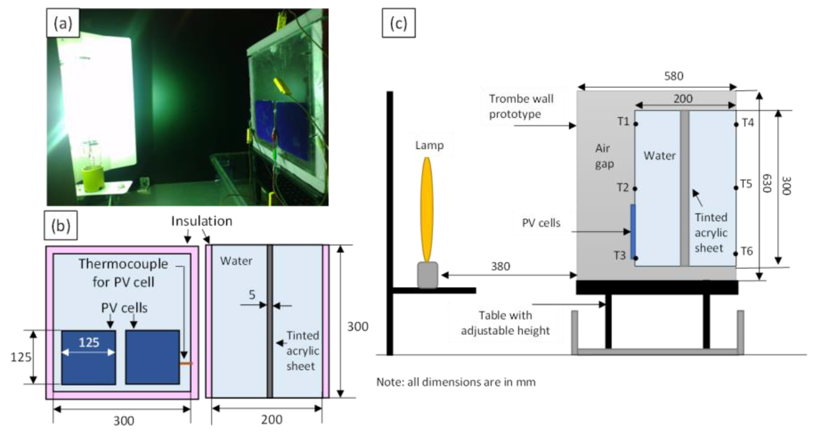
2.1. Experimental Setup

A small Trombe wall prototype was built to experimentally investigate the ability to store solar thermal energy in water storage walls comprising a tinted acrylic sheet. The Trombe wall prototype is framed with wood having a cross section of 3.8 cm × 3.8 cm and its overall dimensions are 58 cm × 36 cm × 68 cm. The wooden frame is insulated with FOAMULAR extruded polystyrene boards and sealed using silicone sealant.
A 3 mm thick clear acrylic sheet with a height and width of 57.5 cm and 42.5 cm, respectively, is tightly fitted and sealed at the front face of the Trombe wall prototype. Similarly, a 3 mm thick acrylic sheet having dimensions of 30 cm × 30 cm is integrated at the back side, such that one can see through the transparent prototype. That is, the presence of the acrylic sheets at the front and back of the Trombe wall prototype allows for light to pass through the structure. An acrylic container with a width, height, and depth of 30 cm, 30 cm, and 20 cm, respectively, is placed within the Trombe wall prototype and is used to store the water. More details about this Trombe wall prototype are available in previously reported work [22]. In this work, monocrystalline silicon PV cells (Maxeon Gen II from Sunpower, with an efficiency rating of ~ 22%) with an area of 125 mm × 125 mm are located at the bottom half of the front surface of the water container as shown in Figure 1a,b. An insulated door with a small opening is used as the side of the prototype to allow users to change the thermal energy storage medium and to adjust the position of the PV cells and thermocouples.
Solar radiation is simulated using a 1000 W Hortilux Blue Metal Halide bulb mounted vertically with a white reflector behind it. The front face of the Trombe wall prototype is 38 cm away from the metal halide bulb, as shown in Figure 1c. Experiments were carried out with and without a 5 mm thick tinted acrylic sheet inserted into the middle of the acrylic container (shown in Figure 1b). By placing the tinted acrylic sheet in the middle of the container (rather than placing it against the inner surface of the front or rear side of the container) its contact area with the water is maximized, which facilitates the transfer of heat generated in the acrylic container to the surrounding water. The tinted acrylic sheet absorbs solar-simulated light, which increases the amount of heat generated in the water. The reflectance (R) and transmittance (T) of the tinted acrylic sheet, and of the clear acrylic sheet used at the front and back of the Trombe wall prototype, were measured over a wavelength range from 220 nm to 1400 nm using a UV-Vis spectrophotometer (Shimadzu 2600i). The reflectance and transmittance of the tinted and clear acrylic sheets was measured using an FTIR spectrometer (VERTEX 70) over the wavelength range from 1400 nm to 25 μm. The absorptance (A) of these acrylic sheets was calculated using the reflectance and transmittance measurements and the equation A + R + T = 1. The transmittance and absorbance of the clear and tinted acrylic sheets are provided in Figure S1 in the Supplementary Materials.
The temperature of the water within the acrylic container was measured over the duration of the experiments using six type K thermocouples (labeled T1 through T6) at the locations shown in Figure 1. Thermocouples T1, T2, and T3 are installed 25 mm from the front surface. T2 is placed at the center of the container, whereas T1 and T3 are 5 mm from the top and bottom of the container, respectively. T4, T5, and T6 follow a similar configuration at the rear side of the container. Two PV cells are attached to the front face of the acrylic container, located at its bottom half as shown in Figure 1b, using silicon heat dissipation pads (Thermalright, Extreme Odyssey II). A thermocouple is placed between the PV cell and the acrylic container to monitor the temperature of the PV cell. This thermocouple is placed between the heat dissipation pad and the acrylic container near the center of the rear side of the PV cell. A data acquisition system (LabJack T7 pro) is used to record the temperature measurements and open circuit voltage of the PV cells. The open circuit voltage of silicon-based PV cells decreases substantially with increasing temperature, whereas the temperature dependence of the short-circuit current is comparatively small [23]. For example, Cuce et al. showed that the open circuit voltage decreases from about 19.5 V to 15 V as the temperature of a c-SiPV cell is increased from 15 °C to 60 °C, while the effects of this temperature increase on the short circuit current were negligible [32]. Thus, in this work, the temperature dependence of the open circuit voltage is used to evaluate the feasibility of the proposed water-based Trombe wall.

2.2. Experimental Procedure

Each experiment consisted of a charging period followed by a discharging period. The solar-simulated light source is turned on at the beginning of the charging period, which lasts for 5 h for all experiments. In this work, 5 h was selected for the duration of the experiments because this is a good representation of the number of peak sun hours received in hot weather climates over the course of one day [33]. After 5 h, the metal halide lamp is turned off and the discharging period begins. During the discharging period, which lasts for 24 h, the heat stored within the water is dissipated to the surroundings. The total duration of each experiment, including the charging and discharging periods, is 29 h.
Experiments were conducted for the twelve cases shown in Table 1. For Cases 1 to 6, PV cells are not used. For Cases 1 and 2, the experimental setup consists of only the water container with and without the acrylic sheet, respectively. Cases 3 and 4 are similar to Cases 1 and 2, respectively, but the top, bottom and sides of the water container are insulated. Cases 5 and 6 are similar to Cases 3 and 4, but the water container is housed within the Trombe wall prototype shown in Figure 1.
For cases 6 to 12, PV cells are placed at the bottom front face of the water container as shown in Figure 1. For Cases 7 and 8, the water container is not housed within the Trombe wall prototype. For Case 8, the tinted acrylic sheet is within the water container, whereas for Case 7, the tinted acrylic sheet is not present. Cases 9 and 10 are similar to Cases 7 and 8, but with the water container housed within the Trombe wall prototype. For Cases 11 and 12, the water is removed from its container to provide a reference for investigating the extent to which the water is able to prevent the temperature of the PV cells from increasing.

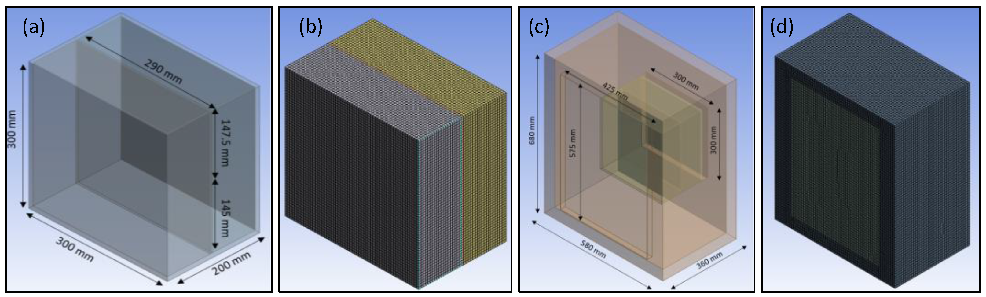
2.3. Numerical Modeling Methods

To numerically model the temperature of the water storage medium over the duration of the charging phase, a three-dimensional model was first created in SOLIDWORKS software. The Reynolds number was determined as ~2500 and the heat transfer and turbulent flow for the cases described in Table 1 were modeled using ANSYS Fluent. All simulations were performed considering the standard k-epsilon turbulence model. The ‘‘SIMPLE’’ algorithm was employed to couple the pressure and velocity and an ambient temperature of 21 °C was used to initialize the model. For all simulations, the time step was 5 s and a quadrilateral mesh of 5 mm was used to discretize the governing equations into a series of algebraic equations. Independence of the results from the time step and mesh size were checked (when decreasing either the time step or the mesh size to half of the values stated above the results changed by less than 0.01%). The convergence criteria of the CFD simulation were based on the residuals of the governing equations to be less than 1.0 × 10⁻⁵. The acrylic container (300 mm × 200 mm × 300 mm) housing the water and tinted acrylic sheet is shown in Figure 2a. The mesh used to numerically model the thermal properties of this water storage medium is shown in Figure 2b. The lab-scale Trombe wall prototype is shown in Figure 2c, and the mesh used to numerically model the prototype is shown in Figure 2d. The thickness of the container is 5 mm on all sides except for the top, where it is 2.5 mm.
To simulate the heat generated when incident light is absorbed a volumetric heat generation term is imparted in the cell zone. The incident light intensity measured 84 m W/cm2 using a power meter (Thorlabs, PM 100D). To simplify the simulations for this feasibility study, it is assumed that 70% of the incident light intensity is absorbed by the acrylic sheet, 20% is absorbed by the water, and 10% is transmitted through the structure. As shown in Figure S1, the absorbance spectrum of the tinted acrylic sheet decreases from over 90% at 300 nm to less than 50% at 1600 nm, and for wavelengths above 2400 nm the absorbance is about 90%. Thus, assuming an average absorption of 70% for the tinted acrylic sheet is reasonable for the feasibility study conducted in this work. The volumetric heat generation term is determined by dividing the intensity of light absorbed by each component by its volume. Furthermore, a convective heat transfer coefficient of 10 W/m2·K is assumed at the top and sides of the structure for all cases, while the bottom of the structure is assumed to be perfectly insulated for all cases.

3. Results

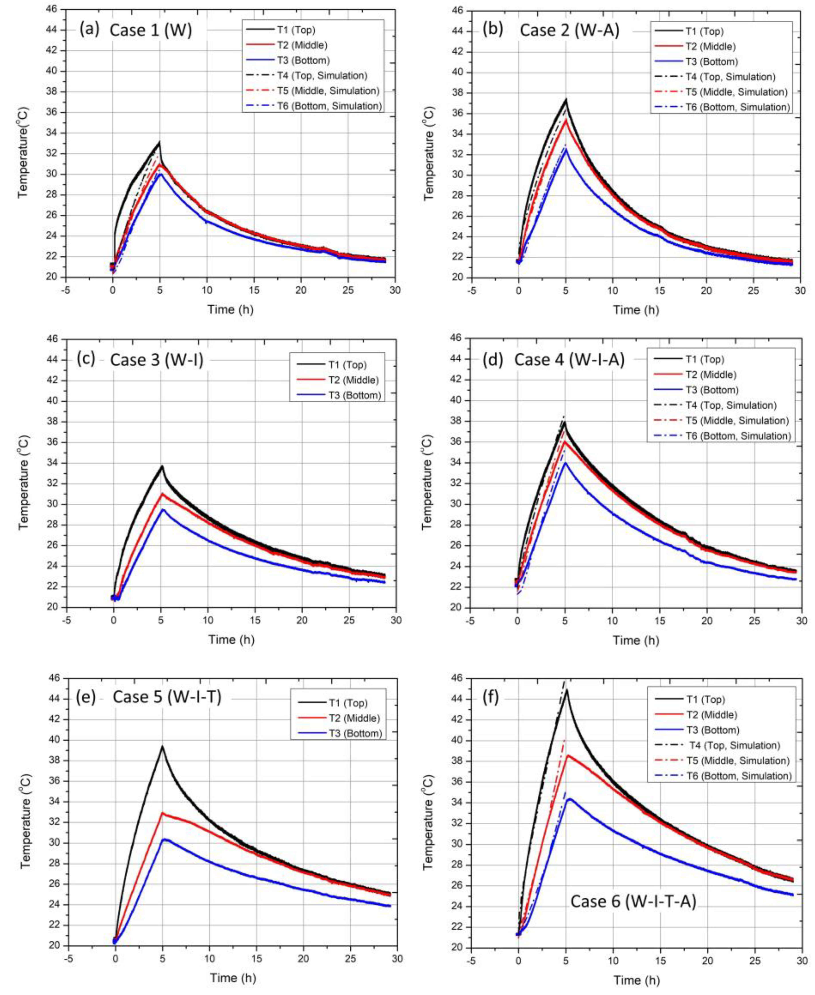
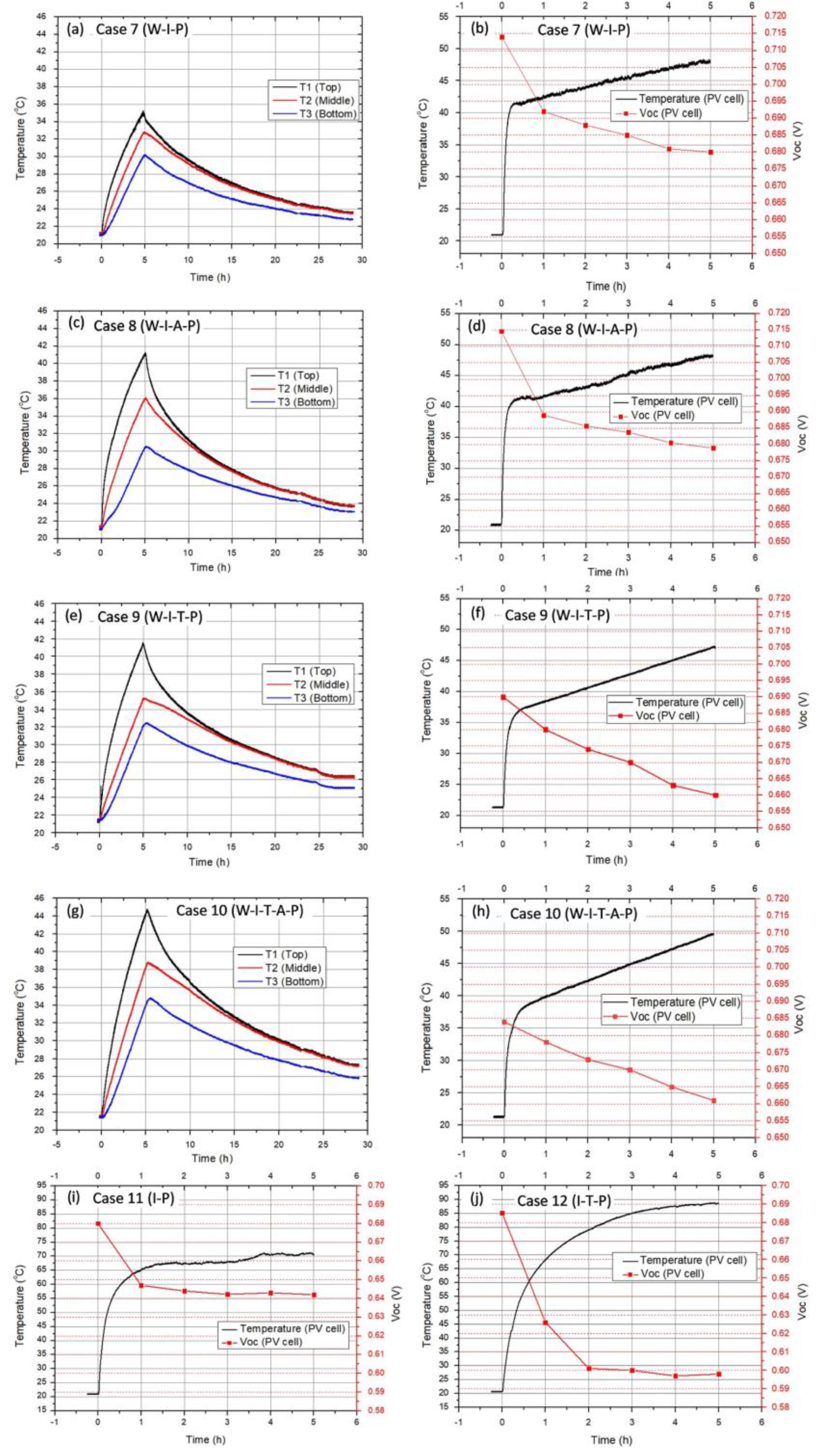
3.1. Experimental Results

The temperature profiles measured at the front of the water container (using T1, T2 and T3 in Figure 1) for Cases 1 to 6 over the 29 h duration of the experiments are shown in Figure 3. The temperature measurements taken near the rear side of the water container were similar to those measured at the front and are shown in Figure S2 in the supplementary material. The results for Case 1 are shown in Figure 3a. The initial temperature of the water at all locations was around 21 °C and the temperature started rising at t = 0 when the lamp was turned on and kept increasing over the next 5 h (over the charging period). As expected, the temperature of the water at the top of the container increased faster than the water at the middle and bottom due to thermal buoyancy forces caused by the density differences associated with water at different temperatures. The temperature at the top, middle and bottom of the water container increased to around 33 °C, 31 °C and 30 °C, respectively, and the average temperature gain for the water was around 10 °C over the charging period. At the end of the charging period, the lamp was turned off and the discharging period began. The water temperature decreased over the discharging phase as heat was lost to the surroundings and the temperature of the water at the end of the discharging period was about 21.5 °C.
The results for Case 2 are shown in Figure 3b. The initial temperature of the water was about 21.5 °C and the temperature at the top, middle and bottom of the water container increased to approximately, 37 °C, 35 °C and 32.5 °C, respectively, by the end of the charging phase. Notably, the temperature of the water at the end of the charging phase is greater for Case 2 than for Case 1, which is attributed to the heat generated when a portion of the incident light is absorbed by the tinted acrylic sheet.
The temperature profiles for Case 3 are shown in Figure 3c. Compared to Case 1, the addition of the insulation at the sides of the water container results in a small increase in the water temperature throughout the container. In comparing the results from Case 3 to those of Case 2, it can be noted that inserting the tinted glass sheet at the center of the water container results in a larger temperature increase than adding insulation at the sides of the container. However, the ability to retain the stored thermal energy is better for Case 3 than for Case 2. For example, during the first five hours of the discharging phase (at the 10 h mark of the experiment) the temperature of the water at the top of the acrylic container decreased by 9 °C for Case 2 and by 5 °C for Case 3.
The temperature profile measurements for Case 4 are shown in Figure 3d. With the addition of both the insulation and the tinted acrylic sheet the water temperature at the end of the charging phase is increased to 38 °C. Figure 3e, which plots the results for Case 5, shows the water temperature can be significantly increased by placing the water container in the Trombe wall prototype. When the tinted acrylic sheet is inserted into the water container within the Trombe wall prototype (Case 6, shown in Figure 3f), the temperature of the water at the top of the container is further increased to 45 °C. Moreover, the results from the numerical simulations over the charging phase while the water is subjected to solar simulated light are shown as the dashed lines in Figure 3b,d,f. The results from the experiment and simulations are in good agreement and are within 2 °C by the end of the charging phase for all locations (including the temperature at the top, middle and bottom of the water storage medium).
The maximum increase in temperature, which occurs at the top of the water container at the end of the charging phase is shown for Cases 1 through 10 in Figure 4. The lowest increase in temperature is ∆Tmax = 11.7 °C for Case 1, whereas the highest increase of ∆Tmax = 23.6 °C occurs for Case 6.
The addition of the PV cells at the front bottom face of the acrylic container generally caused an increase in ∆Tmax. For example, in comparing Cases 3 (W-I) and 7 (W-I-P), the addition of the PV cells resulted in an increase from ∆Tmax = 12.7 °C to ∆Tmax = 14.0 °C. In comparing Cases 4 (W-I-A) and 8 (W-I-A-P), the addition of the PV cells resulted in an increase from ∆Tmax = 15.3 °C to ∆Tmax = 19.9 °C. However, when comparing Cases 6 and 10, a slight decrease from ∆Tmax = 23.6 °C to ∆Tmax = 23.3 °C occurs with the addition of the PV cells when the Trombe wall prototype and tinted acrylic sheet are present in the experimental setup. Based on these results the heat generated when incident light is absorbed by the PV cells can cause the temperature of the water to increase during the charging phase if the amount of light being converted to heat in the water is low or if the insulation is relatively poor. However, for the case when the Trombe wall prototype and tinted acrylic sheet are present the temperature of the water is already elevated, and the addition of the PV cells does not have a significant effect on the water temperature.
The temperature profile for the water and PV cell for Case 7 are shown in Figure 5a,b, respectively. The open circuit voltage, Voc, of the PV cell is also shown in Figure 5b. In this work, the temperature and open circuit voltage of the PV cells were measured only during the charging phase. At the beginning of the charging phase, the output voltage is about 0.715 V, and this value decreases to 0.68 V by the end of the charging phase. This decrease in Voc is attributed to the increase in the PV cell temperature. Before the solar-simulated light is turned on, the temperature of the PV cell is about 21 °C. Once the light is turned on, the PV cell temperature is quickly increased to about 42 °C after the first 15 min of the charging phase. The PV cell temperature continues to rise gradually to a maximum temperature of 47 °C at the end of the charging phase.
The water and PV cell temperature profiles for Case 8 are shown in Figure 5c,d, respectively. Similarly to Case 7, for Case 8, the temperature of the PV cell increases from 21 °C before the charging phase begins to about 47 °C when the charging phase is completed. Likewise, the value of Voc decreases from 0.715 V to about 0.68 V. Figure 5e shows the temperature profiles in the water-based thermal storage medium for Case 9 and Figure 5f shows the temperature and open circuit voltage of the PV cell over the duration of the charging phase. The temperature of the PV cell increases from 21 °C at the onset of the charging phase to 47 °C at the end of the charging phase. At the beginning of the charging phase the open circuit voltage is 0.69 V, which is less than that for Cases 7 and 8 because the incident light intensity for Case 9 is reduced due to absorption and reflection by the acrylic window at the front face of the Trombe wall prototype. By the end of the charging phase, the open circuit voltage is reduced to 0.66 V due to the temperature rise of the PV cell.
The temperature profiles of the water within the Trombe wall prototype for Case 10 are shown in Figure 5g and the corresponding measurements for the temperature and Voc of the PV cell are shown in Figure 5h. The temperature of the PV cell increases from 21 °C to 49 °C during the charging phase and Voc decreases from 0.685 V to 0.66 V over the same time period. The temperature and Voc of the PV cell during the charging phase for Cases 11 and 12 are shown in Figure 5i,j, respectively. For case 11, Voc decreases from 0.68 V to about 0.64 V as the temperature of the PV cell increases from 21 °C to slightly over 70 °C over the five-hour duration that the PV cell is subjected to solar-simulated light. For Case 12, the temperature of the PV cell increases from 21 °C to about 89 °C, and Voc decreases from 0.685 to less than 0.6 V.
The ability for the cooler water at the bottom of the water storage medium to act as a heatsink that reduces the extent to which the temperature of the PV cell rises is clear from the data listed in Table 2. The temperature at the bottom of the water storage medium near its front side (T3) at the end of the charging phase ranges from 30.2 °C to 34.8 °C for Cases 7 through 10. The corresponding temperature of the PV cell ranges from 48.0 to 49.7 °C for Cases 7 through 10. However, for Cases 11 and 12, when the water is not present in the water storage medium, the temperature of the PV cell greatly increases to 71.4 °C and 90 °C, respectively. Furthermore, Voc decreases from 0.68 V to 0.64 V for Case 11 and from 0.658 V to less than 0.6 V for Case 12 while being subjected to the incident solar radiation over five hours. Notably, the drop in the output voltages observed for Cases 11 and 12 are comparable to those reported in the literature for the corresponding increase in temperature [34,35].

3.2. Results from the Numerical Simulations

Schematic diagrams of a full-sized Trombe wall are shown in Figure 6a,b. Similar to the small-scale Trombe wall prototype, the clear water storage container has a depth of 20 mm, and the tinted acrylic sheet resides at its midplane. For the full-scale Trombe wall configuration, there is a 100 mm thick air channel between the water storage medium and the indoor wall of the building. Furthermore, as shown in Figure 6a, it is assumed that PV cells are placed on the bottom half of the front face of the water storage medium. There are 6 rows and 17 columns of PV cells (102 PV cells in total), each with a facial area of 125 mm × 125 mm, such that almost half of the bottom surface of the Trombe wall is covered with PV cells. The temperature at the top, middle and bottom of the full scale Trombe wall is plotted in Figure 6c. In simulating these results, it was assumed that the heat generation terms for the bottom half of the structure were reduced by 50% due to the presence of the PV cells. Heat generated due to absorption of sunlight in the PV cells was not considered. All other methods used in the simulation are similar to those described in Section 2.3. As shown by the black line in Figure 6c, under this conservative assumption, the temperature at the top of the water storage medium in the Trombe wall reaches 44 °C when the wall is subjected to sunlight for five hours. Notably, the simulated temperature profiles shown in Figure 6 are comparable to the experimentally measured temperature profiles shown in Figure 5. Nevertheless, it should be noted that the results in Figure 6 are based on rough assumptions for the values of the heat generated when light is absorbed in the Trombe wall and for the heat loss at the boundaries of the structure. Thus, the initial modelling results presented in this feasibility study show the Trombe wall proposed in this work has the potential to effectively provide heated water that is useful for building applications. Subsequent work should include the modelling and fabrication of a large-scale physical prototype to fully validate the concept.

4. Discussion

The results presented in this work demonstrate that Trombe walls can be used to simultaneously provide multiple functions. The semitransparent, water-based Trombe wall can generate and store heated water, allow for some degree of indoor lighting, and produce electric power. For example, the temperature of the water at the top of the acrylic container reached almost 45 °C, while PV cells were attached to the bottom half of its front surface for Case 10, which is sufficient to provide for most hot water applications in buildings [36]. As one example, it has been reported that dishwashers operate efficiently at temperatures as low as 38 °C, and the temperature of water used for showering is typically in the range of 37–40 °C. Moreover, the recommended water temperature in newer washing machines for high efficiency is approximately 49 °C. Furthermore, it has been suggested that the safest temperature for a hot water tank is 49 °C. Considering the temperature of the inlet water for hot water tanks in buildings during warm weather conditions is commonly ~18 °C, the Trombe wall presented in this work could provide preheated water to the hot water tank to minimize the amount fuel it must consume to meet water heating demands [37]. The heated water can also be stored within the Trombe wall and used hours after sunlight is no longer available. For Case 10, the temperature of the heated water is about 37 °C at the ten-hour mark of the experiment (five hours after the light is switched off), which is still useful for most applications in buildings. The stored water could also be used as preheated water that is sent to a boiler. Furthermore, for Case 10, the temperature of the PV cell increased up to about 47 °C, which is not uncommon for PV cells operating in the field [38,39].
The performance of the Trombe wall presented in this work would be enhanced by operating it as a dynamic building envelope [40,41]. The PV Cells and tinted acrylic sheet could be integrated as light-weight panels that can be removed to satisfy varying demand profiles for electric power, heat and indoor lighting. For example, during summer, a tinted acrylic sheet that absorbs more solar irradiance could be used in the Trombe wall to prevent overheating, whereas a lightly tinted acrylic sheet could be used in winter to allow more solar heat and light to enter the building. It should also be noted that there is a tradeoff between the level of daylight provided to the interior of the building through the Trombe wall and maximizing the temperature the water can be heated to. In this regard, the optical properties of the tinted acrylic sheet used in this work could also be optimized. The visible light spectrum extends from 380 nm to 700 nm; however, as shown in Figure S1, the transmitted light spectrum in the range from 800 nm to 1800 nm is fairly high (about 35% on average). It would be preferrable if the tinted acrylic sheet absorbed all the incident solar radiation over this spectral region to heat the water in the storage medium to the greatest extent possible. It should also be noted that coated acrylics can be used in place of the tinted acrylic to provide for a selection of available brightness and colors [42].
Moreover, the performance of the water-based, semitransparent photovoltaic thermal Trombe wall presented herein could be further improved by using semitransparent PV cells [43,44,45,46,47,48] and by using optical coatings to increase the transparency of the Trombe wall window [49,50,51,52]. Semitransparent PV cells transmit light below the bandgap of the PV cells, which would allow more light to be absorbed by the acrylic sheet in the water storage medium. Semitransparent PV cells may also reduce the amount of absorbed and reflected light, which could reduce the temperature in the air channel of the Trombe wall and the PV cell. The results presented herein demonstrate the feasibility of the water-based, semitransparent photovoltaic thermal Trombe wall design. However, further research is required to validate the concept using a full-scale prototype.
There are some practical considerations to take into account when scaling the water-based Trombe wall proposed in this work. The strength of the transparent material used to contain the water would have to be designed to safely withstand the mechanical loads imposed by the water’s weight. Notably, polycarbonate sheets have been fabricated for use in load-bearing structures [53]. Furthermore, supplemental heating may be needed to prevent the water from freezing if the building is unoccupied for long periods in cold climates and its temperature is allowed to drop. Moreover, to keep the stored water clear, it should not be left stagnant and should be filtered prior to entering the storage medium [54,55].

5. Conclusions

In this work, we experimentally investigated the feasibility of using Trombe walls to perform multiple functions during warm weather conditions including (1) heating and storing water for building applications, (2) providing occupants with visibility to the outdoors, and (3) generating electric power. Experiments were carried out on a small-scale prototype comprising a clear water storage container that is inside an insulated enclosure with transparent windows at its front and rear sides. A tinted acrylic sheet was immersed in the water within the clear container and was illuminated with solar-simulated light. Photovoltaic cells were placed at the lower half of the front face of the water storage container. The cooler water at the bottom of the water storage container acted as a heat sink that reduced the extent to which the temperature of the PV cells increased.
The presence of the PV cells on the lower half of the front face of the water container did not have a significant effect on the water temperature. When the PV cells were absent, the temperature of the water at the top of the storage container was elevated to about 46 °C after being subjected to incident solar radiation for five hours. On the other hand, the temperature of the water at the top of the storage container was elevated to almost 45 °C when subjected to solar-simulated radiation over the same timeframe. This result suggests that electric power from the PV cells and hot water can be generated simultaneously in the water-based Trombe wall configuration presented in this work. The prototype also exhibited the ability to store thermal energy, as the temperature at the top of the water container was 37 °C five hours after the solar-simulated light was switched off. This is an important result because it suggests the water-based Trombe wall will be able to satisfy a portion of the demand for heated water in buildings after the sun has set. The results also show the benefits of thermal stratification within the water tank. While the temperature at the top of the water storage medium was about 45 °C, the temperature of the water near the bottom of the storage container did not surpass 35 °C. The relatively cooler water at the bottom of the container functions as an effective heat sink that limits the extent to which the temperature of the PV cells is elevated.
To demonstrate the ability and importance of the water to function as an effective heat sink, the temperature and open circuit voltage of the PV cells was measured with and without water present in the storage container while the Trombe wall prototype was subjected to incident solar-simulated radiation for five hours. When the water was present, the open circuit voltage was about 0.685 V just after the light was turned on. Over the five hour duration that the light was on, the temperature of the PV cell increased to about 50 °C, and the open circuit voltage of the PV cell decreased to 0.66 V. However, for the experiment wherein the light was removed from the container, the temperature of the PV cell increased to almost 90 °C after being subjected to light from the solar simulator for five hours and the open circuit voltage of the PV cell decreased from 0.685 V to less than 0.60 V over this time period.
Further research is required to investigate the feasibility and potential of water-based, semitransparent photovoltaic thermal Trombe walls at full-scale and under actual weather conditions. Nevertheless, the results attained thus far in this work bode well for the potential of this Trombe wall design and warrant its further development.

Supplementary Materials

The following supporting information can be downloaded at: https://www.mdpi.com/article/10.3390/en16041618/s1. Figure S1: Transmittance spectrum for the clear acrylic sample (top left), transmittance spectrum for the tinted acrylic sample (top right), absorptance spectrum for the clear acrylic sample (bottom left) and the absorptance spectrum for the tinted acrylic sample (bottom right). Figure S2: Temperature profiles at the front and back of the water storage medium (measured using thermocouples T1 through T6 in Figure 1) during the charging and discharging periods for the experiments carried out for (a) Case 1, (b) Case 2, (c) Case 3, (d) Case 4, (e) Case 5, (f) Case 6, (g) Case 7, (h) Case 8, (i) Case 9, (j) Case 10.

Author Contributions

Conceptualization, H.S. and P.G.O.; Methodology, S.B., N.S., A.K.K., H.S. and P.G.O.; Formal Analysis, S.B., N.S. and P.G.O.; Investigation, S.B., N.S., A.K.K. and P.G.O.; writing—original draft preparation, S.B., N.S. and P.G.O.; writing—review and editing, S.B., N.S. and P.G.O.; supervision, P.G.O.; funding acquisition, P.G.O. All authors have read and agreed to the published version of the manuscript.

Funding

This research was funded by the Mitacs Globalink Research Internship (GRI) Program and by the Natural Sciences and Engineering Research Council of Canada (NSERC, RGPIN-2017-05987).

Acknowledgments

Assistance provided by Abdallah Alshantaf in fabricating the Trombe wall prototype experimental setup is greatly appreciated. The authors also thank Atousa Pirvaram for assistance with the optical measurements.

Conflicts of Interest

The authors declare no conflict of interest.

References

  1. Cozzi, L.; Gould, T. World Energy Outlook 2022; International Energy Agency: Paris, France, 2022. [Google Scholar]
  2. Löf, G.O.G.; Duffie, J.A.; Smith, C.O. World distribution of solar radiation. Solar Energy 1966, 10, 27–37. [Google Scholar] [CrossRef]
  3. Vaisi, S.; Pilla, F.; McCormac, D.; McCormack, S.J. Towards urban energy density (UED) definition. In Proceedings of the Energy for Sustainability 2015—Sustainable Cities: Designing for People and the Planet, Coimbra, Portugal, 14–15 May 2015. [Google Scholar]
  4. Howard, B.; Parshall, L.; Thompson, J.; Hammer, S.; Dickinson, J.; Modi, V. Spatial distribution of urban energy consumption by end use. Energy Build. 2012, 45, 141–151. [Google Scholar] [CrossRef]
  5. Güneralp, B.; Zhou, Y.; Urge-Vorsatz, D.; Gupta, M.; Sha, Y.; Patel, P.L.; Fragkias, M.; Li, X.; Seto, K.C. Global scenarios of urban density and its impacts on building energy use through 2050. Proc. Natl. Acad. Sci. USA 2017, 114, 8945–8950. [Google Scholar] [CrossRef] [PubMed]
  6. Daigle, Q.; O’Brien, P.G. Heat Generated Using Luminescent Solar Concentrators for Building Energy Applications. Energies 2020, 13, 5574. [Google Scholar] [CrossRef]
  7. Saadatian, O.; Sopian, K.; Lim, C.H.; Asim, N.; Sulaiman, M.Y. Trombe walls: A review of opportunities and challenges in research and development. Renew. Sustain. Energy Rev. 2012, 16, 6340–6351. [Google Scholar] [CrossRef]
  8. Hu, W.; He, J.; Ji, J.; Zhang, S. A review on the application of Trombe wall system in buildings. Renew. Sustain. Energy Rev. 2017, 70, 976–987. [Google Scholar] [CrossRef]
  9. Sergei, K.; Shen, C.; Jiang, Y. A review of the current work potential of a Trombe wall. Renew. Sustain. Energy Rev. 2020, 130, 109947. [Google Scholar] [CrossRef]
  10. Duffie, J.A.; Beckman, W.A. Solar Engineering of Thermal Processes; John Wiley & Sons, Inc.: Hoboken, NJ, USA, 1991; pp. 250–330. [Google Scholar]
  11. Mokni, A.; Lashin, A.; Ammar, M.; Mhiri, H. Thermal analysis of a Trombe wall in various climatic conditions: An experimental study. Solar Energy 2022, 243, 247–263. [Google Scholar] [CrossRef]
  12. Yang, L.; Dhahad, H.A.; Chen, M.; Huang, Z.; Anqi, A.E.; Rajhi, A.A.; Qader, D.N. Transient analysis of buildings with Trombe wall in a southern envelope and strengthening efficacy by adding phase change material. J. Build. Eng. 2022, 55, 104670. [Google Scholar] [CrossRef]
  13. Liu, H.; Li, P.; Yu, B.; Zhang, M.; Tan, Q.; Wang, Y. The performance analysis of high-efficiency dual-channel Trombe wall in winter. Energy 2022, 253, 124087. [Google Scholar] [CrossRef]
  14. Shen, J.; Lassue, S.; Zalewski, L.; Huang, D. Numerical study of classical and composite solar walls by TRNSYS. J. Therm. Sci. 2007, 16, 46–55. [Google Scholar] [CrossRef]
  15. Chan, H.Y.; Riffat, S.B.; Zhu, J. Review of passive solar heating and cooling technologies. Renew. Sustain. Energy Rev. 2010, 14, 781–789. [Google Scholar] [CrossRef]
  16. Stazi, F.; Mastrucci, A.; di Perna, C. The behaviour of solar walls in residential buildings with different insulation levels: An experimental and numerical study. Energy Build. 2012, 47, 217–229. [Google Scholar] [CrossRef]
  17. Stazi, F.; Mastrucci, A.; di Perna, C. Trombe wall management in summer conditions: An experimental study. Solar Energy 2012, 86, 2839–2851. [Google Scholar] [CrossRef]
  18. Gan, G. A parametric study of Trombe walls for passive cooling of buildings. Energy Build. 1998, 27, 37–43. [Google Scholar] [CrossRef]
  19. Jaber, S.; Ajib, S. Optimum design of Trombe wall system in mediterranean region. Solar Energy 2011, 85, 1891–1898. [Google Scholar] [CrossRef]
  20. Torcellini, P.; Pless, S. Trombe Walls in Low-Energy Buildings: Practical Experiences; National Renewable Energy Lab.: Golden, CO, USA, 2004. [Google Scholar]
  21. Mohamad, A.; Taler, J.; Oclon, P. Trombe Wall Utilization for Cold and Hot Climate Conditions. Energies 2019, 12, 285. [Google Scholar] [CrossRef]
  22. Singh, H.; O’Brien, P.G. Semi-transparent water-based Trombe walls for passive air and water heating. Buildings 2022, 12, 1632. [Google Scholar] [CrossRef]
  23. Skoplaki, E.; Palyvos, J.A. On the temperature dependence of photovoltaic module electrical performance: A review of efficiency/power correlations. Solar Energy 2009, 83, 614–624. [Google Scholar] [CrossRef]
  24. Dubey, S.; Sarvaiya, J.N.; Seshadri, B. Temperature dependent photovoltaic (PV) efficiency and its effect on PV production in the world–a review. Energy Procedia 2013, 33, 311–321. [Google Scholar] [CrossRef] [Green Version]
  25. Temaneh-Nyah, C.; Mukwekwe, L. An investigation on the effect of operating temperature on power output of the photovoltaic system at University of Namibia Faculty of Engineering and IT campus. Proceeding of the 2015 Third International Conference on Digital Information, Networking, and Wireless Communications (DINWC), Moscow, Russia, 3–5 February 2015; pp. 22–29. [Google Scholar]
  26. Rahman, M.M.; Hasanuzzaman, M.; Abd Rahim, N. Effects of operational conditions on the energy efficiency of photovoltaic modules operating in Malaysia. J. Clean. Prod. 2017, 143, 912–924. [Google Scholar] [CrossRef]
  27. Perraki, V.; Kounavis, P. Effect of temperature and radiation on the parameters of photovoltaic modules. J. Renew. Sustain. Energy 2016, 8, 013102. [Google Scholar] [CrossRef]
  28. Hu, Z.; He, W.; Hu, D.; Lv, S.; Wang, L.; Ji, J.; Chen, H.; Ma, J. Design, construction and performance testing of a PV blind-integrated Trombe wall module. Appl. Energy 2017, 203, 643–656. [Google Scholar] [CrossRef]
  29. Koyunbaba, B.K.; Yilmaz, Z.; Ulgen, K. An approach for energy modeling of a building integrated photovoltaic (BIPV) Trombe wall system. Energy Build. 2013, 67, 680–688. [Google Scholar] [CrossRef]
  30. Jie, J.; Hua, Y.; Gang, P.; Jianping, L. Study of PV-Trombe wall installed in a fenestrated room with heat storage. Appl. Therm. Eng. 2007, 27, 1507–1515. [Google Scholar] [CrossRef]
  31. Ahmed, O.K.; Hamada, K.I.; Salih, A.M. Performance analysis of PV/Trombe with water and air heating system: An experimental and theoretical study. Energy Sour. Part A Recovery Util. Environ. Eff. 2022, 44, 2535–2555. [Google Scholar] [CrossRef]
  32. Cuce, E.; Cuce, P.M.; Bali, T. An experimental analysis of illumination intensity and temperature dependency on photovoltaic cell parameters. Appl. Energy 2013, 111, 374–382. [Google Scholar] [CrossRef]
  33. NREL. Solar Resource Maps and Data. Available online: https://www.nrel.gov/gis/solar-resource-maps.html (accessed on 27 January 2023).
  34. Singh, P.; Ravindra, N.M. Temperature Dependence of Solar Cell Performance—An Analysis. Solar Energy Mater. Solar Cells 2012, 101, 36–45. [Google Scholar] [CrossRef]
  35. Cotfas, D.T.; Cotfas, P.A.; Machidon, O.M. Study of temperature coefficients for parameters of photovoltaic cells. Int. J. Photoenergy 2018, 1, 1–12. [Google Scholar] [CrossRef]
  36. Marszal-Pomianowska, A.; Jensen, R.L.; Pomianowski, M.; Larsen, O.K.; Jørgensen, J.S.; Knudsen, S.S. Comfort of domestic water in residential buildings: Flow, temperature and energy in draw-off points: Field study in two danish detached houses. Energies 2021, 14, 3314. [Google Scholar] [CrossRef]
  37. Water Temperature and Burns/Scalds. Available online: https://www.canada.ca/en/public-health/services/water-temperature-burns-scalds.html (accessed on 17 October 2022).
  38. Schwingshackl, C.; Petitta, M.; Wagner, J.E.; Belluardo, G.; Moser, D.; Castelli, M.; Zebisch, M.; Tetzlaff, A. Wind effect on PV module temperature: Analysis of different techniques for an accurate estimation. Energy Procedia 2013, 40, 77–86. [Google Scholar] [CrossRef]
  39. Van Sark, W.G.J.H.M. Feasibility of photovoltaic–thermoelectric hybrid modules. Appl. Energy 2011, 88, 2785–2790. [Google Scholar] [CrossRef]
  40. Svetozarevic, B.; Begle, M.; Jayathissa, P.; Caranovic, S.; Shepherd, R.F.; Nagy, Z.; Hischier, I.; Hofer, J.; Schlueter, A. Dynamic photovoltaic building envelopes for adaptive energy and comfort management. Nat. Energy 2019, 4, 671–682. [Google Scholar] [CrossRef]
  41. Tabadkani, A.; Roetzel, A.; Li, H.X.; Tsangrassoulis, A. Design approaches and typologies of adaptive facades: A review. Autom. Constr. 2021, 121, 103450. [Google Scholar] [CrossRef]
  42. Maduru, V.R.; Shaik, S.; Cuce, E.; Afzal, A.; Panchal, H.; Cuce, P.M. UV coated acrylics as a substitute for generic glazing in buildings of Indian climatic conditions: Prospective for energy savings, CO2 abatement, and visual acceptability. Energy Build. 2022, 268, 112231. [Google Scholar] [CrossRef]
  43. Ghosh, A.; Sundaram, S.; Mallick, T.K. Investigation of thermal and electrical performances of a combined semi-transparent PV-vacuum glazing. Appl. Energy 2018, 228, 1591–1600. [Google Scholar] [CrossRef]
  44. Bailey-Salzman, R.F.; Rand, B.P.; Forrest, S.R. Semitransparent organic photovoltaic cells. Appl. Phys. Lett. 2006, 88, 233502. [Google Scholar] [CrossRef]
  45. Yang, Y.; O’Brien, P.G.; Ozin, G.A.; Kherani, N.P. See-through amorphous silicon solar cells with selectively transparent and conducting photonic crystal back reflectors for building integrated photovoltaics. Appl. Phys. Lett. 2013, 102, 221109. [Google Scholar] [CrossRef]
  46. O’Brien, P.G.; Chutinan, A.; Mahtani, P.; Leong, K.; Ozin, G.A.; Kherani, N.P. Selectively transparent and conducting photonic crystal rear-contacts for thin-film silicon-based building integrated photovoltaics. Opt. Express 2011, 19, 17040–17052. [Google Scholar] [CrossRef] [PubMed]
  47. Alrashidi, H.; Issa, W.; Sellami, N.; Sundaram, S.; Mallick, T. Thermal performance evaluation and energy saving potential of semi-transparent CdTe in Façade BIPV. Solar Energy 2022, 232, 84–91. [Google Scholar] [CrossRef]
  48. Uddin, M.M.; Wang, C.; Zhang, C.; Ji, J. Investigating the energy-saving performance of a CdTe-based semi-transparent photovoltaic combined hybrid vacuum glazing window system. Energy 2022, 253, 124019. [Google Scholar] [CrossRef]
  49. Sarkin, A.S.; Ekren, N.; Sağlam, S. A review of anti-reflection and self-cleaning coatings on photovoltaic panels. Solar Energy 2020, 199, 63–73. [Google Scholar] [CrossRef]
  50. Chunxue, J.; Liu, W.; Bao, Y.; Chen, X.; Yang, G.; Wei, B.; Yang, F.; Wang, X. Recent applications of antireflection coatings in solar cells. Photonics 2022, 9, 906. [Google Scholar]
  51. Loh, J.Y.Y.; Puzzo, D.P.; O’Brien, P.G.; Ozin, G.A.; Kherain, N.P. Enhancing photovoltaics with broadband high-transparency glass using porosity-tuned multilayer silica nanoparticle anti-reflective coatings. RSC Adv. 2014, 4, 31188–31195. [Google Scholar] [CrossRef]
  52. Vázquez-Guardado, A.; Boroumand, J.; Franklin, D.; Chanda, D. Broadband angle-independent antireflection coatings on nanostructured light trapping solar cells. Phys. Rev. Mater. 2018, 2, 035201. [Google Scholar] [CrossRef]
  53. Zapałowicz, Z.; Wojnicki, O. Estimation of total solar transmittance for twin-wall polycarbonate sheet with rectangular structure on the basis of experimental research. Energies 2022, 15, 1360. [Google Scholar] [CrossRef]
  54. Brown, K.W.; Gessesse, B.; Butler, L.J.; MacIntosh, D.L. Potential effectiveness of point-of-use filtration to address risks to drinking water in the United States. Environ. Health Insights 2017, 11. [Google Scholar] [CrossRef]
  55. Cescon, A.; Jiang, J. Filtration process and alternative filter media material in water treatment. Water 2020, 12, 3377. [Google Scholar] [CrossRef]
Figure 1. (a) A picture of the lamp and water container with insulation at its sides and bottom and PV cells on the bottom half of its front surface. (b) A schematic diagram showing the front (left) and cross section from the side view (right) of the water container. (c) A schematic diagram showing the side view of the experimental setup.
Energies 16 01618 g001
Figure 2. (a) A diagram of the water storage medium with the tinted acrylic sheet at its midplane. (b) The mesh used to perform the simulations for the water storage medium with the acrylic sheet at its midplane. (c) A diagram of the water storage medium within the small-scale Trombe wall prototype. (d) The mesh used to perform the simulations for the Trombe wall prototype.
Energies 16 01618 g002
Figure 3. Temperature profiles during the charging and discharging periods for (a) just the container with water, (b) the water container with the tinted acrylic sheet inserted at its midplane, (c) the container with water when its sides are insulated, (d) the insulated water container when the tinted acrylic sheet is inserted at the midplane of the water, (e) the Trombe Wall, (f) Trombe wall acrylic sheet.
Energies 16 01618 g003
Figure 4. The temperature increase (ΔTmax) is measured at the top of the acrylic container for Cases 1 to 10. The maximum temperature, Tmax, measured at the top of the water container is also provided above the bar graph for each case.
Energies 16 01618 g004
Figure 5. Temperature profiles of the water for (a) Case 7, (c) Case 8, (e) Case 9, and (g) Case 10. Temperature and open circuit voltage profiles for the PV cell for (b) Case 7, (d) Case 8, (f) Case 9, (h) Case 10, (i) Case 11, and (j) Case 12.
Energies 16 01618 g005
Figure 6. (a) Diagram of a 3 m tall Trombe wall; (b) cross-sectional view of a 3 m tall Trombe wall; (c) comparison of the simulated temperature profiles at the top, middle and bottom of the water storage medium within the 3 m Trombe wall with the small scale prototype.
Energies 16 01618 g006
Table 1. Experimental cases investigated.
CaseWaterInsulationTrombe WallAcrylic Sheet (Tinted)PV CellAbbreviation
1 W
2 W-A
3 W-I
4 W-I-A
5 W-I-T
6 W-I-T-A
7 W-I-P
8 W-I-A-P
9 W-I-T-P
10W-I-T-A-P
11 I-P
12 I-T-P
Table 2. Temperatures and open circuit voltages for Cases 7–12.
CASET3 at the End of the Charging Phase
(°C)
∆T3 at the End of the Charging Phase
(°C)
T of the PV Cell at the End of the Charging Phase
(°C)
∆T for the PV Cell at the End of the Charging Phase
(°C)
Voc at the End of the Charging Phase (V)∆Voc at the end of the Charging Phase (V)
7 (W-I-P)30.29.348.027.10.6800.034
8 (W-I-A-P)30.69.548.227.40.6790.036
9 (W-I-T-P)32.511.148.727.60.6700.028
10 (W-I-T-A-P)34.813.349.728.50.6680.024
11 (I-P)71.450.50.6420.038
12 (I-T-P)88.868.20.6000.068
Disclaimer/Publisher’s Note: The statements, opinions and data contained in all publications are solely those of the individual author(s) and contributor(s) and not of MDPI and/or the editor(s). MDPI and/or the editor(s) disclaim responsibility for any injury to people or property resulting from any ideas, methods, instructions or products referred to in the content.

