Article

Numerical Study of the Influence of the Thermal Gas Expansion on the Boundary Layer Flame Flashback in Channels with Different Wall Thermal Conditions

1
Center for Combustion Energy, Tsinghua University, Beijing 100084, China
2
Key Laboratory for Thermal Science and Power Engineering of Ministry of Education, Department of Energy and Power Engineering, Tsinghua University, Beijing 100084, China
3
Department of Applied Physics and Electronics, Umeå University, 90187 Umeå, Sweden
4
Department of Mechanical Engineering, Stanford University, Stanford, CA 94305, USA
5
State Key Laboratory of Explosion Science and Technology, Beijing Institute of Technology, Beijing 100081, China
*
Author to whom correspondence should be addressed.
Energies 2023, 16(4), 1844; https://doi.org/10.3390/en16041844
Submission received: 15 January 2023 / Revised: 6 February 2023 / Accepted: 10 February 2023 / Published: 13 February 2023

Abstract

:
In recent years, boundary layer flame flashback (BLF) has re-emerged as a technological and operational issue due to the more widespread use of alternative fuels as a part of a global effort to promote carbon neutrality. While much understanding has been achieved in experiments and simulations of BLF in the past decades, the theoretical modeling of BLF still largely relies on the progress made as early as the 1940s, when the critical gradient model (CGM) for the laminar flame flashback was proposed by Lewis and von Elbe. The CGM does not account for the modification of the upstream flow by the flame, which has been recently shown to play a role in BLF. The aim of the present work is to gain additional insight into the effects of thermal gas expansion and confinement on the flame-flow interaction in laminar BLF. Two-dimensional simulations of the confined laminar BLF in a channel are performed in this work. The parametric study focuses on the channel width, the thermal gas expansion coefficient, and the heat losses to the wall. This study evaluates the influence of these factors on the critical condition for the flame flashback. By varying the channel width, it is demonstrated that at the critical condition, the incoming flow in narrow channels is modified globally by the thermal gas expansion, while in wider channels, the flow modification by the flame tends to be more local. In narrow channels, a non-monotonic dependence of the critical-condition centerline velocity on the channel width has been identified. The variation of the heat loss to the wall confirms that the wall’s thermal conditions can significantly alter the flashback limit, with the flashback propensity being larger when the thermal resistance of the wall is high. To assess the general applicability of the CGM, the flame consumption speed and the flow velocity near the wall are quantified. The results confirm that the assumption of flame having no influence on the upstream flow, employed in the CGM, is not fulfilled under confinement for a realistic thermal gas expansion. This results in a general disagreement between the simulations and the CGM, which implies that the thermal expansion effects should be accounted for when considering the confined boundary layer flashback limits. It is shown that the critical velocity gradient increases with the gas expansion coefficient for the given channel width and wall thermal condition.

1. Introduction

A wider global utilization of alternative fuels, in particular hydrogen-enriched fuels, has the potential to minimize carbon emissions and accelerate the transition to a carbon-neutral society. At the same time, their introduction may be met with operational challenges, such as flashback, that can lead to combustion device failure [1,2,3,4]. For that reason, the phenomenon of flame flashback has gained renewed interest from the combustion community in recent years.
Flame flashback mechanisms can be generally divided into (a) the flashback in the core flow, (b) the flashback due to pressure-heat release coupling, (c) the combustion-induced vortex breakdown (CIVB), and (d) the flashback in the wall boundary layer [1,5]. The flame flashback in the boundary layer can be further categorized into the unconfined flashback of the flame that is initially stabilized at the exterior of the channel, and the confined flame flashback in the interior of the channel [6]. The present study focuses on the latter.
One of the early systematic studies of the critical condition for the onset of the boundary layer flame flashback was done by Lewis and von Elbe [6]. In their work, a critical gradient model (CGM) was developed that characterizes the relationship between the burning velocity and the incoming flow velocity under the critical condition for a flame flashback. Within the CGM framework, it is assumed that the flame will be blown out if the incoming velocity exceeds the flame-burning velocity at some specific distance from the wall. Additional details on the CGM are provided in Section 2.2.
Subsequently, boundary layer flashback was extensively studied experimentally over the decades [1,7,8,9]. As the computational methods and resources evolved, numerical studies of flame flashback became feasible. In Ref. [10], a 2D cylindrical geometry and a one-step chemical reaction were employed to demonstrate that the critical velocity gradient depends non-monotonically on the tube radius. The range of the tube radii considered was limited due to the computational limitations at the time. In a subsequent study [11], experimental and numerical studies of the unconfined flame flashback were performed for a wide range of slit and pyrex tube burners. In Ref. [11], a modified method of calculating the critical velocity gradient was suggested to address the non-linearity of the velocity profile near the wall in narrow tubes. More recently, Kurdyumov et al. [12,13,14,15] conducted a series of studies on the flame flashback for different Lewis numbers and thermal wall conditions. In particular, in Ref. [14], a parametric study for the unburnt-to-burnt density ratio (thermal gas expansion) θ was performed, which was taken in the range of 5 8 . It was concluded that for the range of θ considered, the critical condition for the flame flashback weakly depends on θ .
The present study addresses several outstanding questions. First, it is aimed at further clarifying the dependence of the critical condition for the flame flashback on the channel width. In Refs. [6,7] it was concluded that the critical velocity gradient is mostly independent of the tube diameter (except for a very narrow channel close to the quenching limit). At the same time, in Refs. [10,11], a fairly strong dependence on the tube diameter was identified. Moreover, it has been shown experimentally [16] that the confinement leads to a shift of the flashback limits towards higher critical velocity gradients. In the present study, we further address this discrepancy, using the 2D planar geometry.
Second, we further investigate the dependence of the critical velocity gradient on the thermal gas expansion for a large yet realistic range of the unburnt-to-burnt density ratios θ , beyond that considered in Ref. [14]. While for most laboratory flames, the unburnt-to-burnt density ratio does not typically exceed 10, it can reach a value of about 14 for the ethylene/oxygen mixtures [17] and attain similar values during cryogenic combustion [18]. In light of these findings, consideration of an extended range of the unburnt-to-burnt density ratios is of fundamental importance.
Third, it has been demonstrated experimentally [19,20] and numerically [21] that the approaching flow is modified significantly during the boundary layer flashback. Thus, the intrinsic assumption of the flame having a negligible effect on the upstream flow field, employed in CGM, is compromised. In the present study, an attempt to comprehensively assess the applicability of the CGM for evaluating the laminar BLF at realistically large thermal expansion coefficients is done. A combined effect of the wall heat loss and the thermal gas expansion on the critical condition for the flame flashback is analyzed, with a focus on the critical velocity gradient and the flow structure around the flame tip.
The present paper is organized as follows: in Section 2, we present the numerical approach and further describe the background of the present work. In Section 3, we present and discuss the results of the numerical simulations. The paper is concluded with a short summary. Nomenclature is provided at the end of the paper.

2. Numerical Approach and Theoretical Background

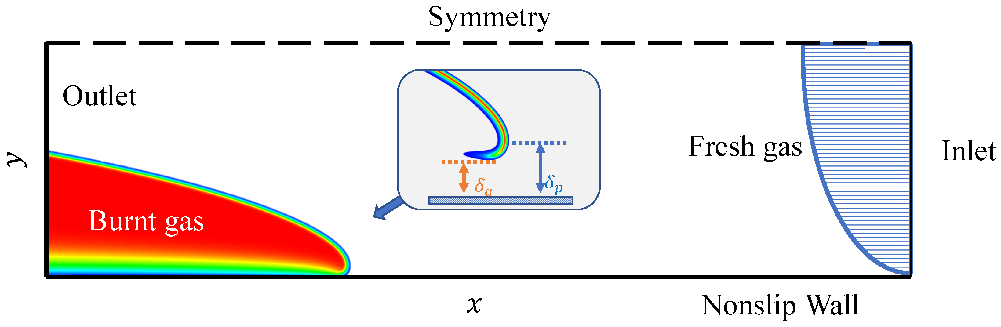
2.1. Basic Equations and Numerical Setup

In this section, a description of the numerical simulations and setup is provided. The flame dynamics are simulated using a 2-D Cartesian Navier–Stokes solver [22] that is based on the cell-centered finite-volume scheme. The solver was initially developed for applications in aerodynamics [23] and later was extensively utilized in various studies of of laminar flame dynamics [24,25,26]. The equations in tensor form read
ρ t + x i ρ u i = 0 ,
t ρ u i + x j ρ u i u j + δ i j P η i j = 0 ,
t ρ ε + 1 2 ρ u i u i + x j ρ u j h + 1 2 ρ u i u i u j + q j u i η i j = 0 ,
t ρ Y + x i ρ u i Y μ S c Y x i = ρ Y τ R exp E a / R p T ,
where Y is the mass fraction of the fuel mixture, ε = Q Y + C V T is the internal energy, h = Q Y + C p T is the enthalpy, Q is the energy released in the reaction, and C V and C p are the heat capacities at the constant volume and pressure, respectively. The stress tensor η i j and the energy diffusion vector q j are given as
η i j = μ u i x j + u j x i 2 3 u k x k δ i j ,
q j = μ C p P r T x j + Q S c Y x j ,
where μ is the dynamic viscosity and P r and S c are the Prandtl and Schmidt numbers, respectively. To avoid the thermal-diffusive instability, we take the unity Lewis number L e P r / S c = 1 , with P r = S c = 0.75 . The thermal and chemical parameters of the fuel mixture are chosen to reproduce the most important properties of typical laboratory flames and, thus, are not specific to a particular fuel. The dynamic viscosity is μ = 1.7 × 10 5 Ns /m 2 . The fuel mixture and burnt matter are assumed to be perfect gases with the equation of state P = ρ R p T / m and with constant molar mass m = 2.9 × 10 2 kg / mol . C V = 5 R p / 2 m , C p = 7 R p / 2 m , where R p 8.31 J / ( mol · K ) is the universal gas constant. The adiabatic index is γ C P / C V = 1.4 . The initial temperature of the fuel mixture is T 0 = 300 K , initial pressure is P 0 = 10 5 P a , and the thermal expansion ratio (coefficient) is θ = T b / T 0 = ρ 0 / ρ b = 4 12 , with subscript “b” standing for the burnt gas. Thus, the energy released in the reaction is Q = ( θ 1 ) C P T 0 . The initial flame Mach number is M a 0 = S L / c s 0 = 0.004 . The right-hand side of Equation (4) describes a single-step irreversible reaction of the first order, with the reaction rate obeying the Arrhenius law with the activation energy E a , and the factor of the time dimension τ R . In the present simulations, the scaled activation energy (Arrhenius number) is ϵ = E a / R p T b = 5 . The factor τ R was adjusted to obtain a particular value of the planar flame velocity S L by solving the associated eigenvalue problem for a standard one-dimensional flame similar to that addressed in Ref. [27]. The flame thickness is conventionally defined [28,29] as δ L μ / ( P r ρ 0 S L ) , where ρ 0 = 1.16 kg/m 3 is the initial mixture density.
Subsonic outflow is applied at the outlet boundary. The non-reflecting inlet boundary condition [28] is used at the inflow boundary, similar to previous studies [30,31,32]. A parabolic velocity profile [33] u x ( y ) = U m a x ( 1 ( ( R y ) / R ) 2 ) is implemented at the inlet, where U m a x is the maximum velocity at the centerline, and R and u x ( y ) are the channel half-width and the velocity component in the x direction, respectively. The symmetry boundary condition is used at the channel centerline, and a non-slip wall boundary condition [26] is used at the bottom wall, see Figure 1. The wall thermal boundary condition is formulated as T ˜ / ( y / δ L ) = B ( T ˜ 1 / θ ) , where the temperature is scaled as T ˜ = T / T b , and the heat transfer parameter B is a dimensionless number that characterizes the thermal resistance of the wall. The approach is similar to that used in Refs. [34,35,36], although the variable scaling is different. B = 0 corresponds to adiabatic walls, and B = corresponds to isothermal walls. The initial internal structure of the flame was imitated by the analytical solution similar to that of Zeldovich and Frank–Kamenetskii [37,38], see Refs. [26,39] for details on the initial solution setting. For the presentation of the results, it is convenient to use non-dimensional variables: length is scaled by δ L , velocity is scaled by S L , and time is scaled by δ L / S L .
In the present simulations, a variable-resolution mesh is employed [26,39], offering considerable savings in computing resources. In such a mesh, a subdomain with a higher resolution contains the flame front and the other parts of the calculation domain use a lower resolution, see, for example, Ref. [39]. Square cells of the size 0.1 0.2 δ L are used in the flame-containing subdomain to ensure a proper resolution of the reaction zone and isotropic flame propagation properties. The grid resolution varies gradually from one subdomain to another along the channel. The total length of the channel L is typically 100 times that of half-width ( L = 100 R ) for eliminating the influence of the inlet boundary condition on the flame dynamics and ensuring that the critical condition can be attained far enough from the inlet. The flame is ignited at the bottom left corner as a sector of burnt gas with radius 5 δ L for each case, similar to Ref. [31]. The critical condition, at which the flame becomes stagnant within the channel, is attained by gradually adjusting the total flow rate at the inlet.
Resolution tests are performed for the cell sizes l / δ L = 0.05 0.4 in the flame subdomain. In the test case, a flame propagation velocity U t i p is quantified for the channel of half-width 60   δ L , with θ = 8 , U m a x / S L = 3 , and the heat transfer parameter B = 10 . The resolution tests are summarized in Table 1, demonstrating the convergence of U t i p . The constant refinement ratio r = 2 is applied. The observed order p of the truncation rate decay [40,41] is p = 2.58 for l = 0.4 , 0.2 , 0.1 , and p = 2.0 for l = 0.2 , 0.1 , 0.05 , in a reasonable agreement with the overall order of approximation. Based on the resolution tests, the cell size in the flame subdomain is taken as l = 0.2   δ L for R / δ L = 20 200 . For the very small channel half-widths R / δ L = 5 20 , an even smaller cell size l = 0.1   δ L is used.

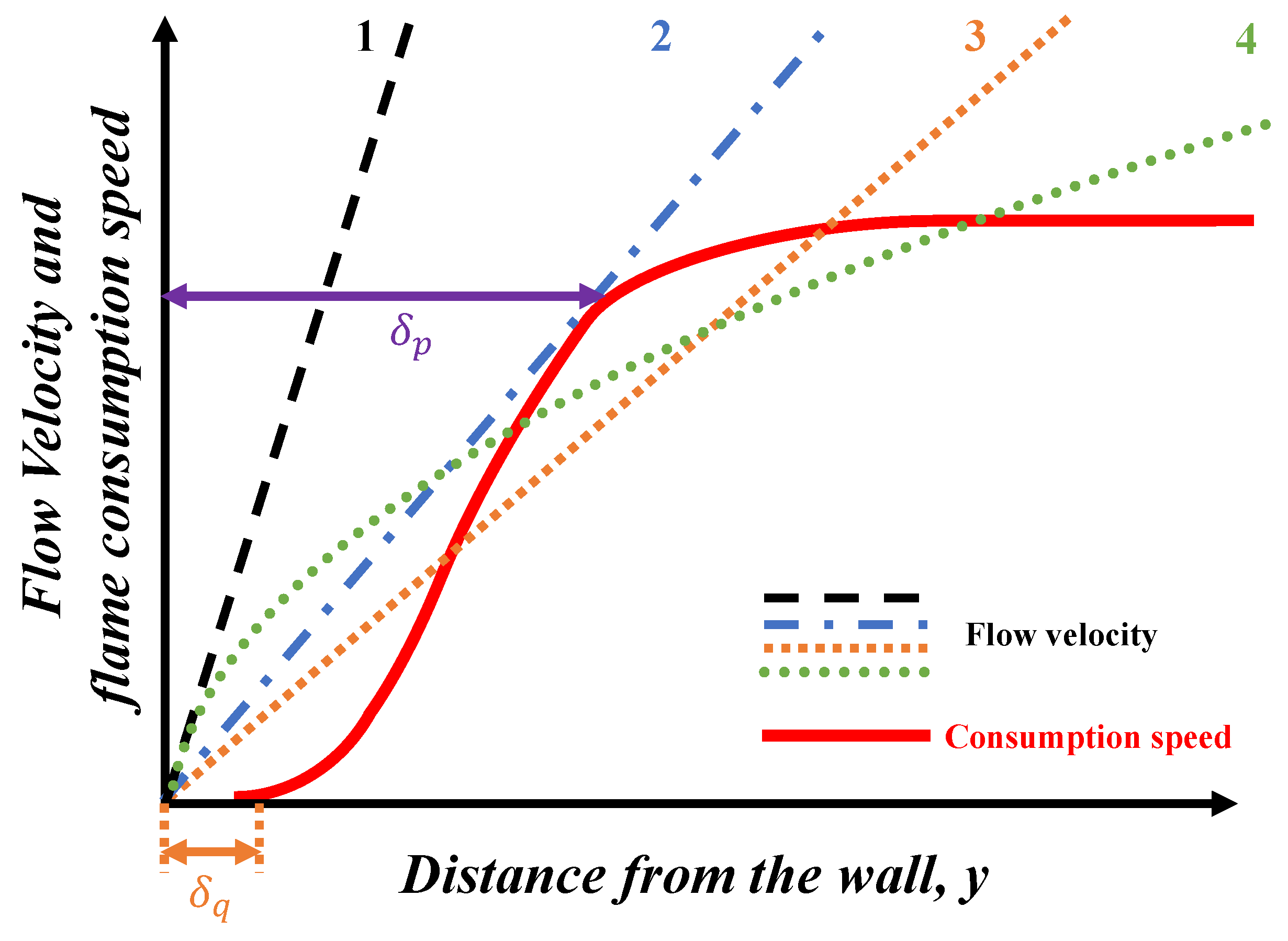
2.2. Critical Condition for the Flame Flashback

In the context of the boundary layer flame flashback, two length scales were previously discussed, the quenching distance δ q and the penetration distance δ p [1,42,43]. The two distances, δ q and δ q , are shown in Figure 2, with a more detailed description of the illustration provided below. Quenching distance δ q is the gap between the wall surface and the location above the wall where the burning rate becomes non-zero [1,44]. Various ways were suggested to measure it experimentally, such as relating it to the minimum distance between the two parallel plates, for which the flame propagation is possible, or estimating it from the minimum flame diameter in a free space [38,43,45].
However, δ q is of limited use for the description of the boundary layer flashback [8,10]. To tackle the problem of the boundary layer flashback propensity, another length scale, called penetration distance δ p , is introduced. Historically, it has been defined in different ways. According to a simpler definition, δ p is the distance from the wall at which the flame consumption speed becomes equal to the laminar burning velocity. Another, more rigorous definition, equates δ p to the distance from the wall to the point where the profile of the flame consumption speed s c ( y ) becomes tangential to the profile of the velocity of the plane-parallel flow [7], as illustrated in Figure 2. Here, the profile of the flame consumption speed s c ( y ) can be calculated as s c ( y ) = ( ρ 0 Y 0 S L ) 1 w ( x , y ) d x , where w ( x , y ) is the local reaction rate, see Equation (4).
The main idea behind the critical gradient model [6,7] (abbreviated as CGM in the text) is summarized as follows. In Figure 2, curve 1 corresponds to the case when the velocity of the incoming flow is greater than the flame consumption speed for all y; the flame will be thus blown downstream by the incoming flow. Curve 2 corresponds to the critical condition, where there is a balance of the flame consumption speed and the incoming flow at the distance δ p from the wall. Curves 3 and 4 correspond to a flashback situation when the flame propagates upstream. For the very narrow channels, the velocity profile near the wall may deviate from a linear one substantially, with curve 4 illustrating this situation.
The near-wall velocity gradient g for the case of a wide channel can be calculated as
g = lim y 0 d u x d y .
Based on the assumptions of the CGM, the penetration distance can be obtained as
δ p = S L g c ,
where g c is the near-wall velocity gradient at the critical condition, which can be calculated from Equation (7).
Early on, it has been reported by Harris et al. [43] that Equation (7) becomes inapplicable at small channel widths, as the velocity profile near the wall is not sufficiently linear in narrow channels. Despite that, Equation (7) has been widely used in experimental studies [6,7,43]. In the numerical and experimental study by Mallens et al. [11], the issue of the non-linearity of the velocity profile at the penetration distance in narrow channels has been addressed. An alternative expression for the critical velocity gradient has been suggested [11]:
g c = 2 U m a x R 1 δ p R .
The velocity distribution in the fully developed laminar channel flow is [33] u x = U m a x ( 1 ( ( R y ) / R ) 2 ) , and the velocity gradient for any y can be expressed as g = 2 U m a x ( 1 y / R ) / R . For the larger channel widths, δ p R , and, as the result, δ p R 0 , therefore the velocity gradient near the wall can be taken as g = 2 U m a x R .

2.3. Influence of the Thermal Expansion on the Planar Flame Structure

To gain the initial understanding of the influence of the thermal gas expansion on the planar adiabatic flame structure for θ = 4 , 8 , 12 , we plot the calculated normalized profiles of temperature T + , fuel mass fraction Y + , and reaction rate w + in Figure 3. It can be observed that the difference in the temperature distribution is rather small, as well as the difference in the mass fraction profiles, while the difference in reaction rate profiles is more evident. The reaction zone is visibly wider for the lower thermal gas expansion coefficients (see the one for θ = 4 ) and is thinner for the higher values of θ . It is noted that the scaled activation energy ϵ = E a / R P T b is kept constant. The variation of the reaction zone thickness can be attributed to the variation of the Zeldovich number Z e = ϵ ( 1 1 / θ ) , which defines the relative thickness of the reaction zone within the standard flame structure [38]. Here we would like to point out that δ L , as defined in Section 2.1, is a mathematical parameter of length dimension rather than a realistic flame thickness, with the latter typically several times larger than δ L [39,46].
It should be noted that in the presence of heat loss near the cold wall, it is expected that the profile of the flame consumption speed in the wall-normal direction may differ for different θ due to different spatial distributions of the reaction rate. We examine the effects of thermal gas expansion on the flame flashback limit and flame structure in more detail in Section 3.1.3 and Section 3.2.

3. Results and Discussion

In this section, we examine the influence of the thermal gas expansion coefficient θ on the flame flashback for different channel widths R and wall thermal conditions defined by heat transfer coefficient B. Different values of θ can be representative of different characteristics of gaseous fuels, such as level of preheating, diluent mass fraction, etc. One of the advantages of the present numerical simulation that employs the chemical kinetics in the form of a one-step reaction is that we can keep the majority of the physical parameters unchanged and only modify one of them independently, for example, the thermal expansion coefficient θ . It is noted that for different θ = 4 12 , the laminar flame speed S L is therefore constant. For the higher θ , the burnt gas temperature T b will be higher. As we will see, the flame flashback can be affected by the wall’s thermal conditions, because heat loss to the wall can significantly change the shape of the reaction zone, as well as the flow structure in the vicinity of the flame.

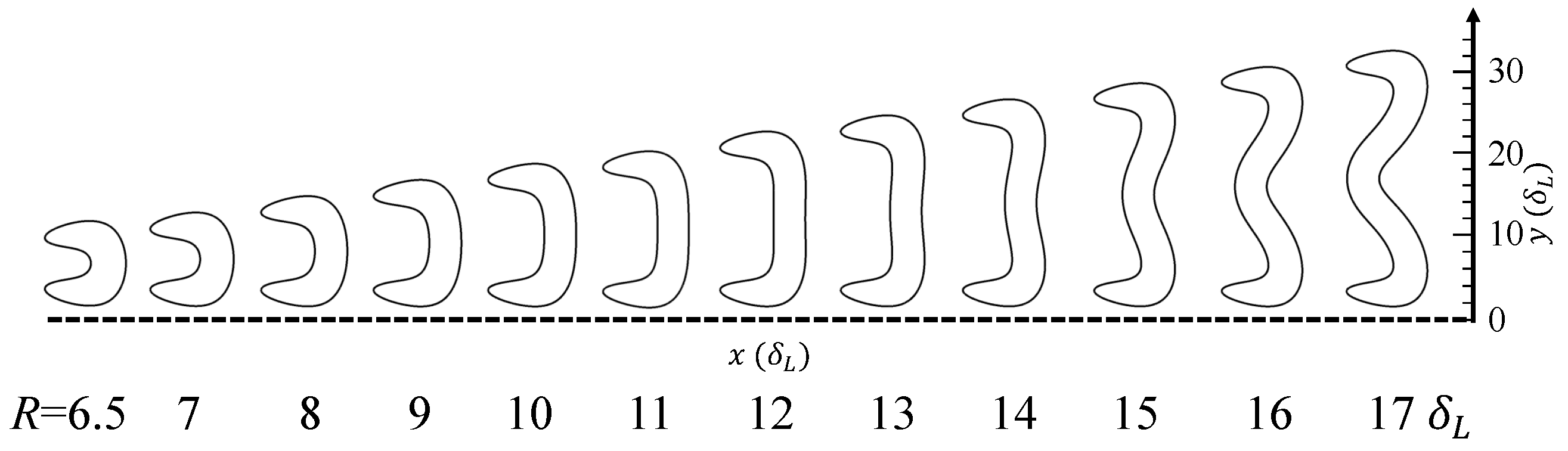
3.1. The Effect of Channel Width

In this subsection, we investigate the effects of the channel width on the flame flashback, in particular focusing on the critical condition for a flame flashback. We perform the numerical study for different channel half-widths ( R / δ L = 6 200 ) and for different thermal expansion coefficients ( θ = 4 , 8 , 12 ).
The flame response to the change of the channel width is found to be qualitatively different for more narrow and more wide channels. There exists a lower limit of the channel width, for which the flame can exist, with the flame being quenched in narrower channels. In narrow channels with a width up to about 20   δ L , the flame shape at the critical condition is visibly different as compared to that in more wide channels. The response of the critical velocity gradient to the channel width is also qualitatively different for narrower and wider channels, as summarized further. Based on these qualitative differences, we distinguish the two ranges of channel widths, dubbed as “small channel width” ( R     20   δ L ) and “medium channel width” ( R   >   20   δ L ). Channels with the width R > 200   δ L are presently not considered due to the computational limitations of the multi-parameter study.

3.1.1. Small Channel Width

In Figure 4, reaction zone shapes are shown for different channel widths at the critical condition for θ = 4 . The shape of the reaction zone is illustrated using the isolines of the normalized reaction rate ( w + = 0.01 ). In the following, we refer to the reaction zone shape as the “flame shape.” For the small channel widths, the flame shape is noticeably affected by both the flow profile and the heat loss to the wall. The lower limit for the channel half-width, below which the flame is quenched, is found to be around R = 6   δ L . For R / δ L = 6.5 10 , the flame shape is convex. With the further increase in the channel width, the flame near the channel’s centerline gets impacted by the flow more strongly and starts to bend. When the channel half-width reaches R = 12   δ L , the flame near the centerline becomes nearly flat. A similar transition from a “mushroom”-shaped flame to a tulip-shaped flame was observed by Hackert et al. [47] for stationary flames in ducts. A flame shape at the critical condition, similar to that obtained at R = 12   δ L , was experimentally observed by Kim et al. [48].
As the channel width is further increased beyond R = 14   δ L , a cusp appears at the flame surface near the centerline, while the reaction zone near the wall becomes convex. The last flame shape in the sequence in Figure 4, R = 17   δ L , can be considered to be representative of a flame configuration in even wider channels. The modification of the flame shape at the critical condition is reminiscent of that observed in Ref. [49].
Figure 5 illustrates the dependence of the critical centerline velocity U m a x , c (centerline velocity at the critical condition) on the channel half-width R. A non-monotonic dependence of U m a x on R is observed within the range of R / δ L = 6.5 14 . In this range of R, the critical centerline velocity U m a x first increases and then decreases with the channel width. Comparing Figure 4 and Figure 5, it can be noted that the flame shape change can be correlated with the changes in the trend for the critical centerline velocity U m a x , c . A local minimum in U m a x , c ( R ) corresponds to the formation of the flame cusp at the centerline. It is worth noting that the higher the gas expansion coefficient θ , the more prominent is the decreasing trend in the critical centerline velocity U m a x , c in the range R = 10 14 .
Once the flame front attains a concave shape at the channel centerline, the critical U m a x , c starts to increase again for R > 14   δ L . The critical centerline velocity increases with the channel width, preventing the flame from propagating upstream near the channel centerline. This leaves the only option for the flame to propagate upstream closer to the wall, where the upcoming flow velocity is lower. Lee and Tsai [50] provide a similar explanation of the transition from “mushroom”-shaped flames to tulip-shaped flames for steadily propagating flames in tubes.
In Figure 6, the flame shape at the critical condition is represented by the normalized reaction rate and temperature isolines for different channel widths. Streamlines are plotted in white. For the smallest channel half-width R = 6.5   δ L , the flame is convex at the centerline, and the streamlines are deflected from the centerline towards the walls. For the channel half-width R = 12   δ L the flame front at the centerline is flat; thus, the flame “tip” is still at the centerline, so qualitatively, it is similar to that of R = 6.5   δ L . For R = 20   δ L , the leading point shifts to the vicinity of the wall, where the flame propagation is able to balance the lower velocity. It can be seen that the streamlines are affected by the flame only within a limited distance ahead of the flame tip at the critical condition.

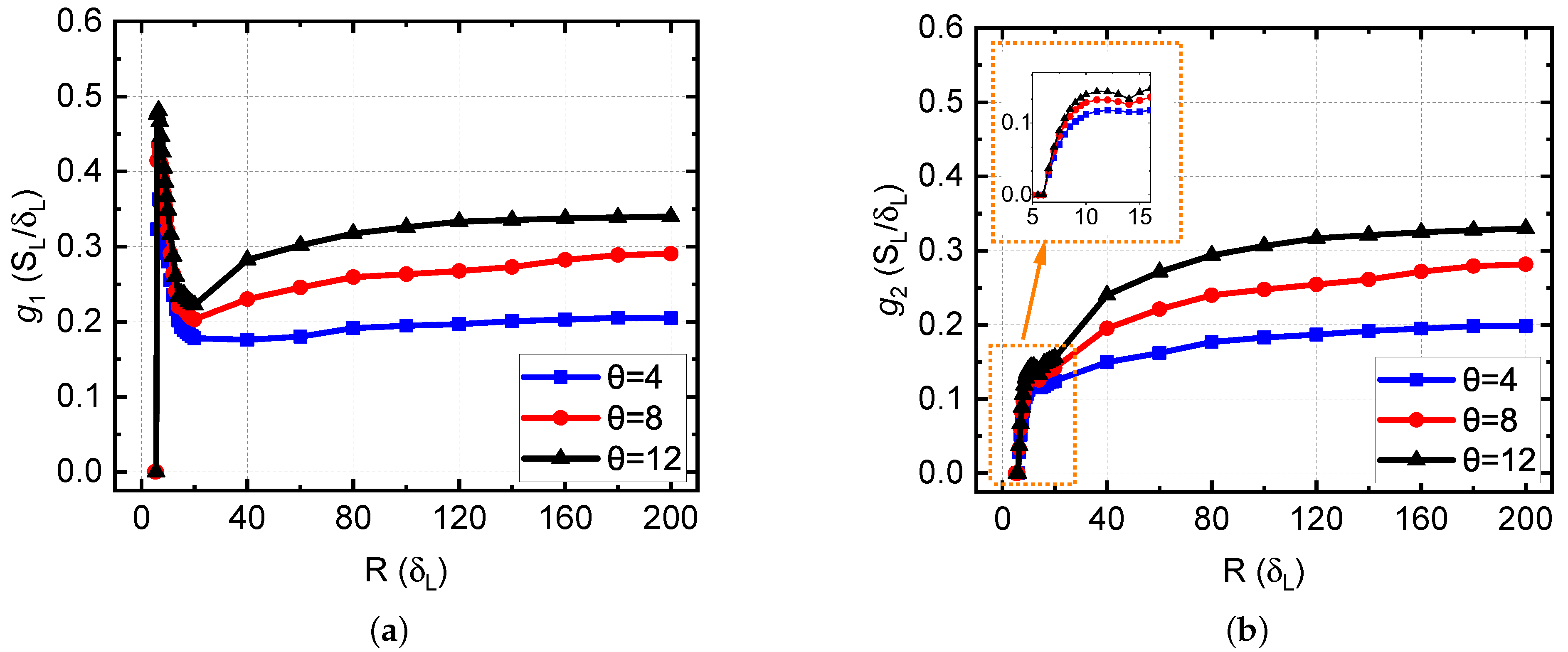
3.1.2. Critical Velocity Gradients for Small to Medium Channel Widths

In this subsection, we quantify the critical velocity gradients for the channel half-widths within the range R / δ L = 6 200 and discuss the influence of the definition of the critical velocity gradient on its trends for the small channel widths. First, we define the critical velocity gradient, which is commonly used as a simplified local characteristic of the flow ahead of a flame tip during the flashback. In accordance with the discussion of Section 2, we consider and compare the two definitions of the critical velocity gradient, g 1 = 2 U m a x R and g 2 = 2 U m a x R ( 1 δ p R ) . Figure 7 illustrates the dependence of the critical velocity gradients g 1 and g 2 on the channel half-width R. It is evident that Figure 7a,b show different trends for smaller channel widths.
It is noted that Lewis and colleagues [6,7,43] used g 1 = 2 U m a x R , and U m a x was calculated based on the mass flow rate. The term δ p / R in g 2 is expected to be small for the experimental studies in wider channels and tubes. For the case of small channel widths, R = 6 20   δ L , Figure 7a shows a decreasing trend for g 1 , while Figure 7b shows an increasing trend for g 2 , indicating an inconsistency in the two definitions for this range of channel widths. Harris et al. [43] pointed out that the CGM model may not be suitable for burners with a very small size. If the channel width is similar to the quenching distance in magnitude, the parabolic shape of the velocity profile at the critical condition would have an impact on the difference between g 1 and g 2 . It is noted that in Figure 7, as the channel width increases beyond 20   δ L , g 1 and g 2 converge for all θ . The reason is that, as the channel width increases, δ p / R becomes smaller, and the velocity profile in the vicinity of δ p becomes almost linear, see Figure 2 for reference. Figure 7 also indicates that for the larger expansion coefficients θ , the critical gradient is larger, i.e. the flashback propensity is higher for the larger thermal expansion.
In Figure 8, the effect of the channel width on the flow structure at the critical condition is further illustrated. The normalized reaction rate w + is shown with contour lines. The negative values of the vertical component of the velocity u y 0 (downward direction of the flow) are shown in uniform gray. It is seen that, as the channel width increases, the gray zone ahead of the flame is shrinking for R = 20 ,   40 ,   60   δ L . However, the difference between the gray zones ahead of flame for R = 60 and 120   δ L is small. This is in agreement with the convergent trend for the critical velocity gradient for the larger channel widths in Figure 7. It can be attributed to the diminishing effect of the channel confinement on the flow around the flame tip. It is seen that the wall-normal component of the velocity just above the flame tip becomes larger as the channel width increases from R = 20   δ L to 60   δ L .
The dependence of the critical velocity gradient on the channel width was discussed by Lewis et al. [6], Lee and Tien [10], and Mallens et al. [11]. The general conclusion is similar: when the channel width is large enough, the critical velocity gradient tends to be independent of the channel width.
The comparison of the consumption speed s c ( y ) and the horizontal component of the upstream velocity u x ( y ) at the critical condition is shown in Figure 9 for different channel widths and θ = 4 . It is seen from Figure 9 that the CGM doesn’t appear to be directly applicable, irrespective of the channel width considered, as generally u x ( y ) is not tangent to s c ( y ) at the critical condition, thus contradicting the basic assumptions of the CGM, see Section 2.2. For a smaller channel half-width R = 20 , s c is generally larger than u x in the vicinity of the wall ( y < δ p ) at the critical condition. For the larger channel half-widths, R = 60 and 120   δ L , the agreement with CGM is somewhat better, the latter showing the best agreement with CGM. Based on Figure 8 and Figure 9, it can be suggested that a stronger influence of thermal gas expansion in narrower channels due to a stronger confinement effect leads to a stronger modification of the flow upstream by the flame. As the result, the flashback can happen at a lower critical gradient as compared to that predicted using the CGM, as corroborated by Figure 9.

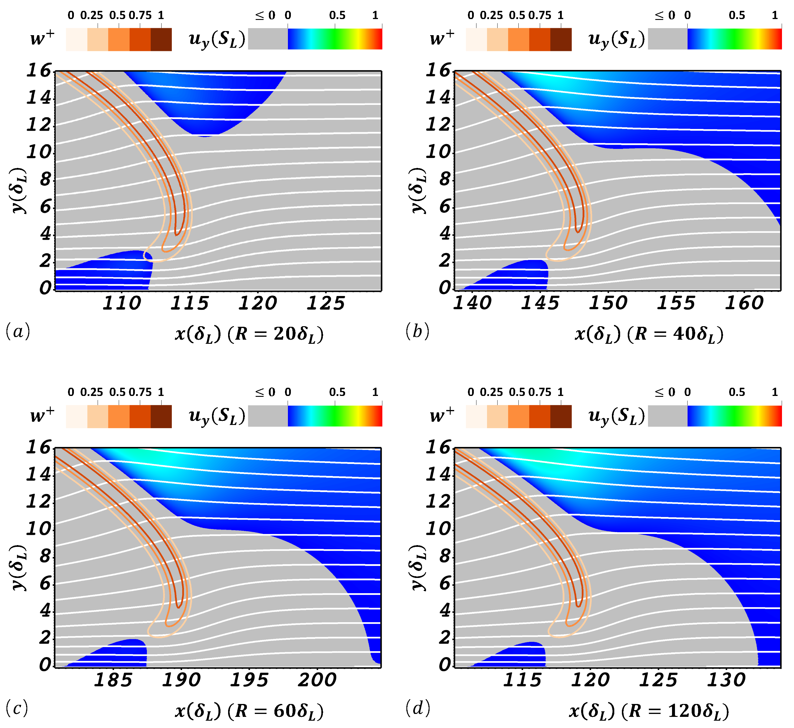
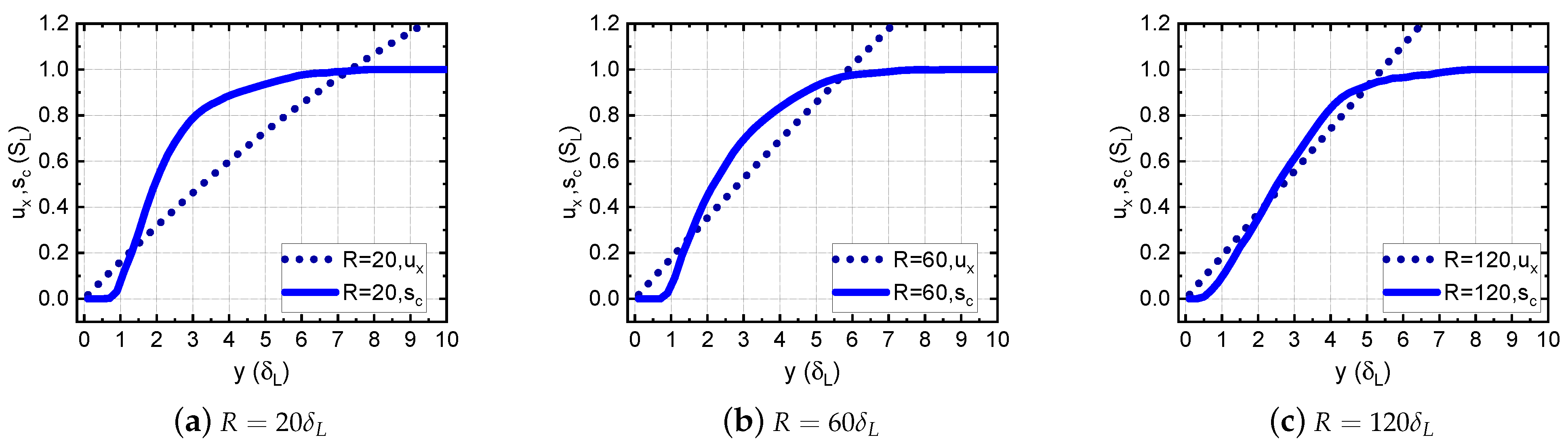
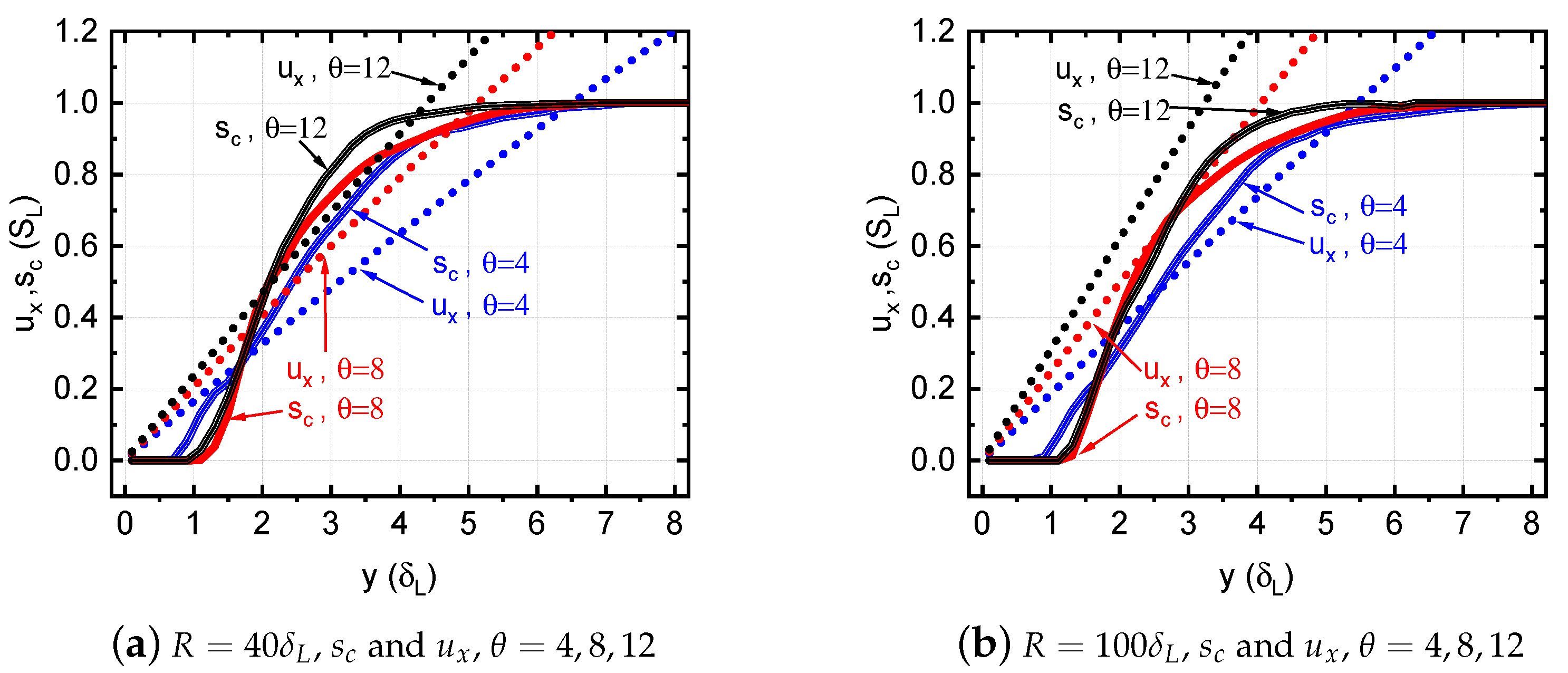
3.1.3. Effect of Thermal Expansion in Channels of Different Width

In this subsection, the effects of the thermal expansion coefficient on the flame characteristics at the critical condition are studied for a range of channel half-widths, and for θ = 4 , 8 , 12 . The dependence of the critical velocity gradient g 2 on the thermal expansion coefficient θ in channels with isothermal walls is shown in Figure 10 for different channel half-widths R. It is seen that the larger the thermal expansion coefficient θ , the larger the critical velocity gradient for a given channel width. This indicates that the gas expansion at the flame front has an impact on the flow upstream of the flame, promoting the upstream flame propagation and affecting the boundary layer flashback limits.
In Figure 11, the flame shapes near the wall are shown for different θ and two different channel widths under the critical condition. From Figure 11, we can see that δ q at the critical condition (as illustrated in Figure 2) does not significantly change with θ in the chosen range of R. For the higher θ , the reaction zone given by w + looks thinner, which can be explained by the same reasoning as presented in the discussion of Figure 3: the smaller the θ , the smaller the Zeldovich number Z e = ϵ ( 1 1 / θ ) , which leads to a thicker reaction zone relative to the total flame thickness. As seen from Figure 11, when flame shapes for different channel widths are overlapped, the flame portion close to the wall remains almost unchanged when R is varied, but the change in θ results in a more significant elongation of the flame tip.
To evaluate the validity of CGM at different θ , the flame consumption speed s c ( y ) and the incoming flow velocity u x ( y ) under the critical condition are plotted in Figure 12 for two values of channel half-width, R = 40   δ L (a) and R = 100   δ L (b). It is seen that for most cases, there is a disagreement with CGM. It is assumed that if the upstream flow remains unperturbed by the flame, there will be a tangency point for s c ( y ) and u x ( y ) , as illustrated in Figure 2. From Figure 12a, we notice that for all θ , s c exceeds u x in a certain range of y at the critical condition, which contradicts the CGM. In Figure 12b, there is a visible agreement with CGM for θ = 8 , however, this appears to be a coincidence, as for the other two values of θ there is no agreement with CGM. From both Figure 12a,b, it can be noted that with an increasing θ , the slope of u x will increase at the critical condition, in agreement with the results of Figure 10, while s c profile will be modified with θ only slightly for a given R.
Overall, from Figure 12, we can conclude that a straightforward application of CGM to s c ( y ) and u x ( y ) , similar to Figure 2, is not very meaningful for realistic gas expansion, as the assumption of no upstream flow modification by the flame is not fulfilled for the range of θ and R considered. The s c ( y ) and u x ( y ) profiles at the critical condition are found to be strongly dependent on the thermal expansion coefficient θ and the channel half-width R.

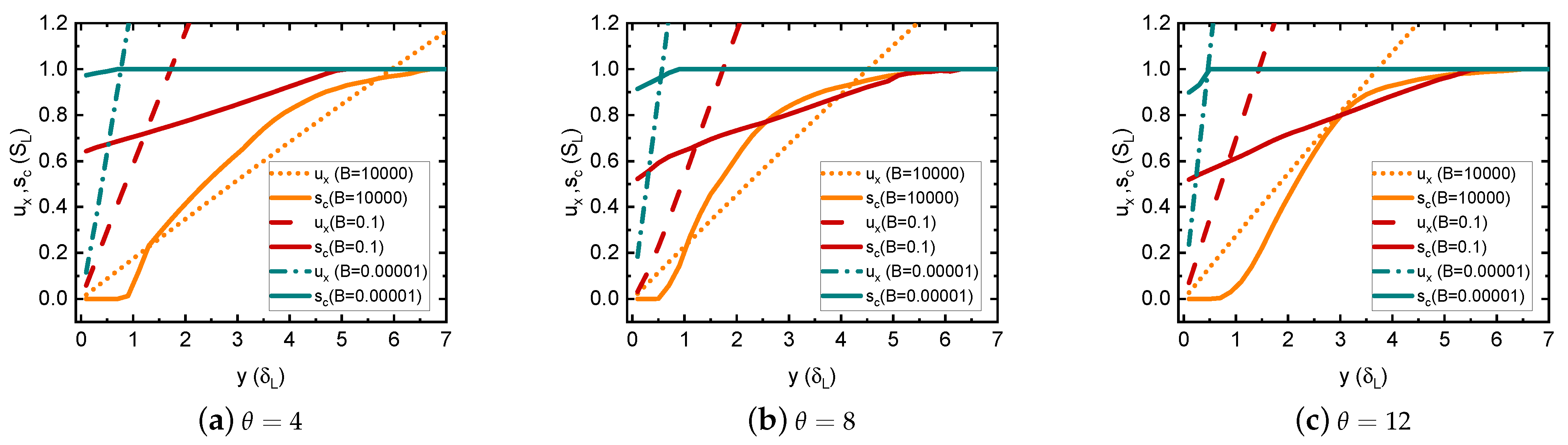
3.2. Effect of Wall Thermal Conditions for Different Thermal Gas Expansion Coefficients

Wall thermal condition is another key factor that affects the flame flashback propensity. In the present numerical study, we use the wall thermal boundary condition described in Section 2.1, that employs the heat transfer parameter B, to regulate the heat flux at the wall. In this section, the channel half-width is set to a constant R = 60   δ L . In the parametric study, three values of θ are used, θ = 4 , 8 , 12 , and the heat transfer coefficient B ranges from 0 to + .
Figure 13 shows the critical velocity gradient g 2 for different thermal gas expansion coefficients θ = 4 12 at the different heat transfer parameters B = 0 , 0.01 , , 10 4 for the same channel half-width R = 60   δ L . It is seen that with the increase of the thermal expansion coefficient θ for a given heat transfer parameter B, the critical velocity gradient becomes larger. Comparing the critical velocity gradients g 2 for different wall thermal conditions in Figure 13b, we can see that for the adiabatic wall, the critical velocity gradient g 2 is higher than that for an isothermal wall and all values of B in between, in qualitative agreement with the results of Ref. [14]. The difference in g 2 for adiabatic and isothermal walls is 5 10 times.
In order to better understand the flame and flow configuration at the critical condition and different B and θ , the reaction rate fields and streamlines are visualized in Figure 14. It is seen that, for a given θ , as the heat transfer parameter B decreases from the very large values (at which B is effectively near-infinity, i.e., the wall is isothermal) to near-zero, the penetration distance δ p decreases significantly, disappearing at lower B. Thus, for a given θ , as B is decreased, the flame moves closer to the wall and becomes harder to be blown downstream.
It is also seen that as the thermal expansion coefficient θ is increased, the divergence of the streamlines increases, indicating the increased propensity of the flame to modify the flow even in a critical condition. This tendency is most noticeable for the larger B (Figure 14a–c).
Finally, we compare the consumption speed s c ( y ) and the incoming flow velocity profiles u x ( y ) at the critical condition in Figure 15 for different θ and B.
It is seen that with the increase of the heat transfer coefficient B, the height (y-coordinate) of the cross-point between s c ( y ) and u x ( y ) is increasing as well. It is noted that for B = 0.1 , flame consumption speed s c is below S L wall for all θ considered. The results indicate that the concept of the critical gradient model (CGM) [6] may, in principle, become inapplicable when the thermal resistance of the walls is high. Based on Figure 14 and Figure 15, it can be suggested that the influence of the thermal gas expansion on the flame-flow interaction is more significant at larger heat transfer coefficients B.

4. Summary

This work is aimed at providing additional insights into tackling the flame flashback problem. The combined effects of the thermal gas expansion, wall thermal conditions, and channel width on the limits of the confined laminar boundary layer flashback in channels are investigated. It is shown that for the small channel widths, the flow upstream of the flame is globally modified at the critical condition. For the larger channel widths, the critical velocity gradient is nearly independent of the channel width. In order to assess the applicability of the critical gradient model for the confined boundary layer flashback, the flame consumption speed and the incoming flow velocity profile near the wall are quantified. Two-dimensional fields of the reaction rate and the streamlines are analyzed for a range of thermal expansion coefficients and wall heat transfer parameters. It is demonstrated that the thermal gas expansion affects the flame shape and the flow ahead of the flame significantly in the critical condition. Generally, this results in a lack of agreement of the simulation results with the critical gradient model (CGM). It is concluded that a straightforward application of the CGM may not be meaningful, as the upstream flow can be modified significantly by the thermal gas expansion, thus invalidating the key assumption of the CGM.
The critical velocity gradient is shown to considerably depend on the thermal expansion coefficient in both isothermal and adiabatic limits for the wall thermal condition. The effects of the channel width, the thermal gas expansion, and the wall thermal conditions, on the critical condition for the confined laminar BLF, are summarized as follows:
  • In narrow channels, with the channel half-width R 20   δ L , the centerline velocity at the critical condition U m a x , c depends on the channel width non-monotonically;
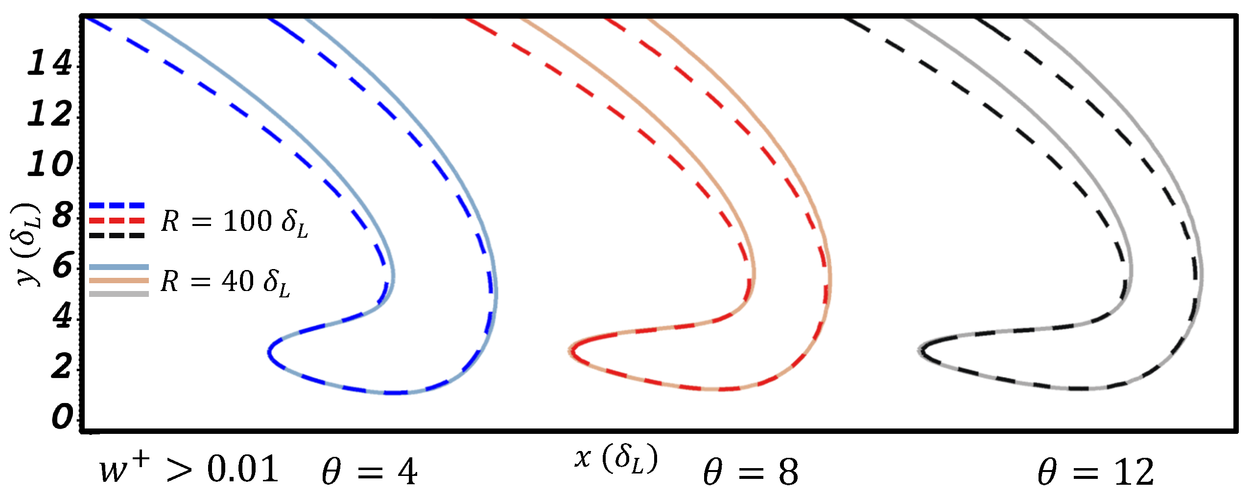
  • In wider channels, R > 20   δ L , the critical velocity gradient g c grows gradually with the channel width, reaching a nearly constant value for a given gas expansion coefficient;
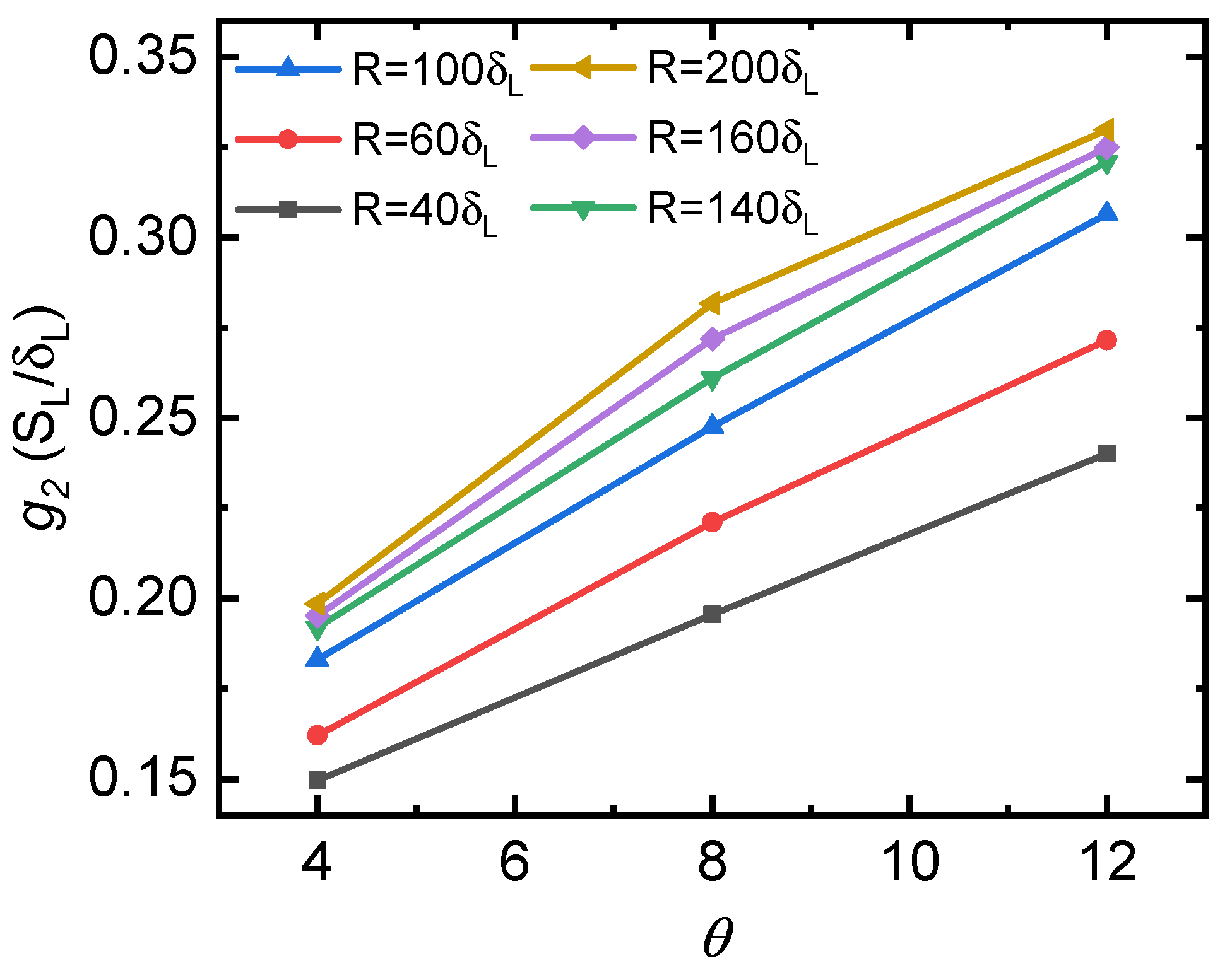
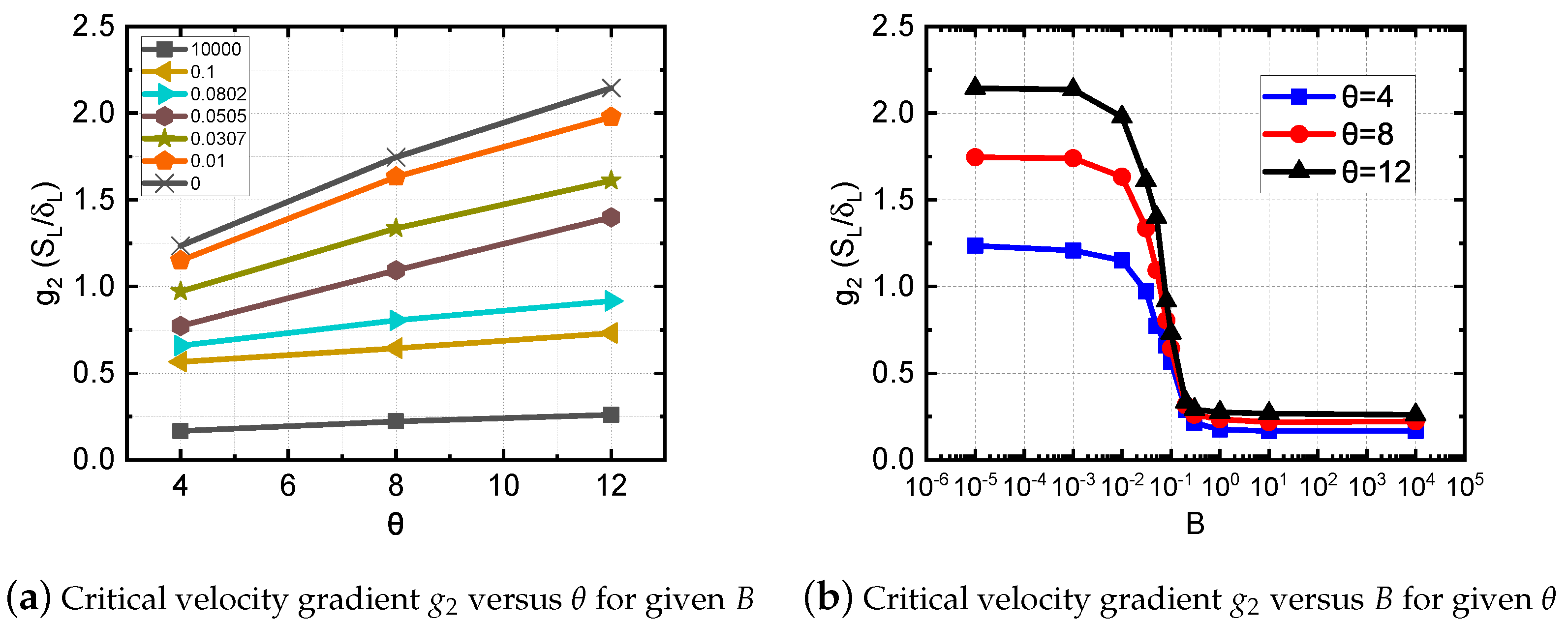
  • The critical velocity gradient increases with the gas expansion coefficient for given channel width and wall thermal condition;
  • It is confirmed that the critical velocity gradient for the adiabatic wall can be an order of magnitude higher than that for the isothermal wall.
From a practical standpoint, it can be concluded that the flashback propensity is larger when the thermal resistance of the wall is high, and when the unburnt-to-burnt density ratio is large.

Author Contributions

Conceptualization, D.M.V.; methodology, K.H., D.M.V. and H.Z.; software, H.Z., K.H. and D.M.V.; validation, K.H.; resources, D.M.V.; writing—original draft preparation, K.H. and D.M.V.; writing—review and editing, H.Z. and W.H.; investigation, K.H.; visualization, K.H.; supervision, D.M.V.; funding acquisition, D.M.V. and W.H. All authors have read and agreed to the published version of the manuscript.

Funding

This research was funded by the National Natural Science Foundation of China (NSFC) grant numbers 52176118 and 51750110503, and by the State Key Laboratory of Explosion Science and Technology (Beijing Institute of Technology) through the opening of Project No. KFJJ21–10M. W.H. is supported by Shaanxi Institute of Applied Physical Chemistry grant number 6142602210408. Computations and data handling were enabled by resources provided by the Swedish National Infrastructure for Computing (SNIC) at High Performance Computing Center North (HPC2N), partially funded by the Swedish Research Council through Grant Agreement No. 2018-05973. The APC was funded by MDPI.

Institutional Review Board Statement

Not applicable.

Data Availability Statement

The data presented in this study are available on request from the corresponding author. The data are not publicly available due to large disk usage.

Acknowledgments

The authors are grateful to Kun Zhang for implementing the thermal boundary conditions. D.V. is grateful to Andrea Gruber for useful discussions.

Conflicts of Interest

The authors declare no conflict of interest. The funders had no role in the design of the study; in the collection, analyses, or interpretation of data; in the writing of the manuscript; or in the decision to publish the results.

Abbreviations and Nomenclature

BLFboundary layer flashback
CGMcritical gradient model
CIVBcombustion-induced vortex breakdown
Bwall heat transfer parameter
c s sound speed
C P heat capacity at constant pressure
C V heat capacity at constant volume
E a activation energy
gvelocity gradient
lcell size
L e Lewis number
M a flame propagation Mach number
Ppressure
porder of truncation error decay
P r Prandtl number
q j energy diffusion vector
Qenergy release from the reaction
Rchannel half-width
R p universal gas constant
S c Schmidt number
s c consumption speed
S L unstretched laminar burning velocity
ttime
Ttemperature
U , u velocity
wreaction rate
xaxial coordinate
yradial coordinate
Ymass fraction of fuel
Z e Zeldovich number
δ i j Kronecker delta
δ L laminar flame thickness
δ q quenching distance
δ p penetration distance
ε total energy per unit volume
ϵ Arrhenius number
η i j stress tensor
γ adiabatic index
θ gas expansion ratio
μ dynamic viscosity
ρ density
τ R factor of time dimension in the Arrhenius law
Subscripts
0initial value
bburnt gas
ccritical
m a x maximum (centerline)
t i p flame tip
Superscripts
+normalized value
Other designations
scaled value

References

  1. Kalantari, A.; McDonell, V. Boundary layer flashback of non-swirling premixed flames: Mechanisms, fundamental research, and recent advances. Prog. Energy Combust. Sci. 2017, 61, 249–292. [Google Scholar] [CrossRef]
  2. Leicher, J.; Schaffert, J.; Cigarida, H.; Tali, E.; Burmeister, F.; Giese, A.; Albus, R.; Görner, K.; Carpentier, S.; Milin, P.; et al. The Impact of Hydrogen Admixture into Natural Gas on Residential and Commercial Gas Appliances. Energies 2022, 15, 777. [Google Scholar] [CrossRef]
  3. Jiang, X.; Tang, Y.; Liu, Z.; Raman, V. Computational Modeling of Boundary Layer Flashback in a Swirling Stratified Flame Using a LES-Based Non-Adiabatic Tabulated Chemistry Approach. Entropy 2021, 23, 567. [Google Scholar] [CrossRef] [PubMed]
  4. Vigueras-Zuniga, M.O.; Tejeda-del Cueto, M.E.; Vasquez-Santacruz, J.A.; Herrera-May, A.L.; Valera-Medina, A. Numerical Predictions of a Swirl Combustor Using Complex Chemistry Fueled with Ammonia/Hydrogen Blends. Energies 2020, 13, 288. [Google Scholar] [CrossRef]
  5. Eichler, C.T. Flame Flashback in Wall Boundary Layers of Premixed Combustion Systems. Ph. D. Thesis, Technical University of Munich, Munich, Germany, 2011. [Google Scholar]
  6. Lewis, B.; von Elbe, G. Stability and structure of burner flames. J. Chem. Phys. 1943, 11, 75–97. [Google Scholar] [CrossRef]
  7. Von Elbe, G.; Mentser, M. Further studies of the structure and stability of burner flames. J. Chem. Phys. 1945, 13, 89–100. [Google Scholar] [CrossRef]
  8. Berlad, A.L.; Potter, A.E. Relation of boundary velocity gradient for flash-back to burning velocity and quenching distance. Combust. Flame 1957, 1, 127–128. [Google Scholar] [CrossRef]
  9. Potter, A.E. 5-Flame Quenching. In Progress in Combustion Science and Technology; Ducarme, J., Gerstein, M., Lefebvre, A.H., Eds.; Pergamon Press: New York, USA, 1960; Volume 1, pp. 145–181. [Google Scholar] [CrossRef]
  10. Lee, S.T.; T’ien, J.S. A numerical analysis of flame flashback in a premixed laminar system. Combust. Flame 1982, 48, 273–285. [Google Scholar] [CrossRef]
  11. Mallens, R.M.M.; De Goey, L.P.H. Flash-back of Laminar Premixed Methane/Air Flames on Slitand Tube Burners. Combust. Sci. Technol. 1998, 136, 41–54. [Google Scholar] [CrossRef]
  12. Kurdyumov, V.; Fernández, E.; Liñán, A. Flame flashback and propagation of premixed flames near a wall. Proc. Combust. Inst. 2000, 28, 1883–1889. [Google Scholar] [CrossRef]
  13. Kurdyumov, V.N.; Fernandez-Tarrazo, E. Lewis number effect on the propagation of premixed laminar flames in narrow open ducts. Combust. Flame 2002, 128, 382–394. [Google Scholar] [CrossRef]
  14. Kurdyumov, V.; Fernández-Tarrazo, E.; Truffaut, J.M.; Quinard, J.; Wangher, A.; Searby, G. Experimental and numerical study of premixed flame flashback. Proc. Combust. Inst. 2007, 31, 1275–1282. [Google Scholar] [CrossRef]
  15. Jiménez, C.; Fernández-Galisteo, D.; Kurdyumov, V.N. DNS study of the propagation and flashback conditions of lean hydrogen-air flames in narrow channels: Symmetric and non-symmetric solutions. Int. J. Hydrogen Energy 2015, 40, 12541–12549. [Google Scholar] [CrossRef]
  16. Eichler, C.; Baumgartner, G.; Sattelmayer, T. Experimental investigation of turbulent boundary layer flashback limits for premixed hydrogen-air flames confined in ducts. J. Eng. Gas Turbines Power 2012, 134, 011502. [Google Scholar] [CrossRef]
  17. Wu, M.H.; Wang, C.Y. Reaction propagation modes in millimeter-scale tubes for ethylene/oxygen mixtures. Proc. Combust. Inst. 2011, 33, 2287–2293. [Google Scholar] [CrossRef]
  18. Kuznetsov, M.; Denkevits, A.; Veser, A.; Friedrich, A. Flame propagation regimes and critical conditions for flame acceleration and detonation transition for hydrogen-air mixtures at cryogenic temperatures. Int. J. Hydrogen Energy 2022, 47, 30743–30756. [Google Scholar] [CrossRef]
  19. Ebi, D.; Clemens, N.T. Experimental investigation of upstream flame propagation during boundary layer flashback of swirl flames. Combust. Flame 2016, 168, 39–52. [Google Scholar] [CrossRef]
  20. Ranjan, R.; Clemens, N.T. Insights into flashback-to-flameholding transition of hydrogen-rich stratified swirl flames. Proc. Combust. Inst. 2021, 38, 6289–6297. [Google Scholar] [CrossRef]
  21. Gruber, A.; Chen, J.H.; Valiev, D.; Law, C.K. Direct numerical simulation of premixed flame boundary layer flashback in turbulent channel flow. J. Fluid Mech. 2012, 709, 516–542. [Google Scholar] [CrossRef] [Green Version]
  22. Eriksson, L.E. A Third Order Accurate Upwind-Biased Finite-Volume Scheme For Unsteady Compressible Viscous Flow; Volvo Aero Corporation: Trollhättan, Sweden, 1993. [Google Scholar]
  23. Eriksson, L.E. Flow solution on a dual-block grid around an airplane. Comput. Methods Appl. Mech. Eng. 1987, 64, 79–93. [Google Scholar] [CrossRef]
  24. Valiev, D.; Bychkov, V.; Akkerman, V.; Law, C.K.; Eriksson, L.E. Flame acceleration in channels with obstacles in the deflagration-to-detonation transition. Combust. Flame 2010, 157, 1012–1021. [Google Scholar] [CrossRef]
  25. Demirgok, B.; Ugarte, O.; Valiev, D.; Akkerman, V. Effect of thermal expansion on flame propagation in channels with nonslip walls. Proc. Combust. Inst. 2015, 35, 929–936. [Google Scholar] [CrossRef]
  26. Valiev, D.; Bychkov, V.; Akkerman, V.; Eriksson, L.E.; Law, C.K. Quasi-steady stages in the process of premixed flame acceleration in narrow channels. Phys. Fluids 2013, 25, 096101. [Google Scholar] [CrossRef]
  27. Han, Y.; Modestov, M.; Valiev, D.M. Effect of momentum and heat losses on the hydrodynamic instability of a premixed equidiffusive flame in a Hele–Shaw cell. Phys. Fluids 2021, 33, 103608. [Google Scholar] [CrossRef]
  28. Poinsot, T.; Veynante, D. Theoretical and Numerical Combustion; RT Edwards, Inc.: Morningside, QLD, Australia, 2005. [Google Scholar]
  29. Adebiyi, A.; Abidakun, O.; Akkerman, V. Acceleration of Premixed Flames in Obstructed Pipes with Both Extremes Open. Energies 2020, 13, 4094. [Google Scholar] [CrossRef]
  30. Feng, R.; Gruber, A.; Chen, J.H.; Valiev, D.M. Influence of gas expansion on the propagation of a premixed flame in a spatially periodic shear flow. Combust. Flame 2021, 227, 421–427. [Google Scholar] [CrossRef]
  31. Ding, S.; Huang, K.; Han, Y.; Valiev, D. Numerical study of the influence of wall roughness on laminar boundary layer flashback. Phys. Rev. Fluids 2021, 6, 023201. [Google Scholar] [CrossRef]
  32. Feng, R.; Valiev, D. Influence of gas expansion on the velocity and stability limits of stationary curved flames in channels. Combust. Sci. Technol. 2022. [Google Scholar] [CrossRef]
  33. Schlichting H, G.K. Boundary-Layer Theory, 9th ed.; Springer: Berlin/Heidelberg, Germany, 2016. [Google Scholar]
  34. Kagan, L. On the transition from deflagration to detonation in narrow channels. Math. Model. Nat. Phenom. 2007, 2, 16. [Google Scholar] [CrossRef] [Green Version]
  35. Kagan, L.; Sivashinsky, G. On the Transition from Deflagration to Detonation in Narrow Tubes. Flow Turbul. Combust. 2010, 84, 423–437. [Google Scholar] [CrossRef]
  36. Huang, J.; Han, W.; Gao, X.; Wang, C. Effects of heat loss and viscosity friction at walls on flame acceleration and deflagration to detonation transition. Chin. Phys. B 2019, 28, 074704. [Google Scholar] [CrossRef]
  37. Zeldovich, I.B.; Barenblatt, G.I.; Librovich, V.B.; Makhviladze, G.M. Mathematical Theory of Combustion and Explosions; Consultants Bureau: New York, NY, USA, 1985. [Google Scholar]
  38. Law, C.K. Combustion Physics; Cambridge University Press: Cambridge, UK, 2006. [Google Scholar]
  39. Valiev, D.; Bychkov, V.; Akkerman, V.; Eriksson, L.E.; Marklund, M. Heating of the fuel mixture due to viscous stress ahead of accelerating flames in deflagration-to-detonation transition. Phys. Lett. A 2008, 372, 4850–4857. [Google Scholar] [CrossRef]
  40. Versteeg, H.; Malalasekera, W. An Introduction to Computational Fluid Dynamics: The Finite Volume Method; Pearson Education Limited: London, UK, 2007. [Google Scholar]
  41. AlKhabbaz, M.; Kodakoglu, F.; Valiev, D.; Akkerman, V. Impacts of wall conditions on flame acceleration at the early stages of burning in channels. Phys. Rev. Fluids 2022, 7, 013201. [Google Scholar] [CrossRef]
  42. Dugger, G.L. Flame stability of preheated propane-air mixtures. Ind. Eng. Chem. 1955, 47, 109–114. [Google Scholar] [CrossRef]
  43. Harris, M.; Grumer, J.; Elbe, G.V.; Lewis, B. Burning velocities, quenching, and stability data on nonturbulent flames of methane and propane with oxygen and nitrogen 1: Application of theory of ignition, quenching, and stabilizationto flames of propane and air. Symp. Combust. Flame Explos. Phenom. 1948, 3, 80–89. [Google Scholar] [CrossRef]
  44. Alliche, M.; Haldenwang, P.; Chikh, S. Extinction conditions of a premixed flame in a channel. Combust. Flame 2010, 157, 1060–1070. [Google Scholar] [CrossRef]
  45. Takizawa, K.; Igarashi, N.; Takagi, S.; Tokuhashi, K.; Kondo, S. Quenching distance measurement of highly to mildly flammable compounds. Fire Saf. J. 2015, 71, 58–68. [Google Scholar] [CrossRef]
  46. Akkerman, V.; Bychkov, V.; Petchenko, A.; Eriksson, L.E. Flame oscillations in tubes with nonslip at the walls. Combust. Flame 2006, 145, 675–687. [Google Scholar] [CrossRef]
  47. Hackert, C.; Ellzey, J.; Ezekoye, O. Effects of thermal boundary conditions on flame shape and quenching in ducts. Combust. Flame 1998, 112, 73–84. [Google Scholar] [CrossRef]
  48. Kim, N.I.; Kataoka, T.; Maruyama, S.; Maruta, K. Flammability limits of stationary flames in tubes at low pressure. Combust. Flame 2005, 141, 78–88. [Google Scholar] [CrossRef]
  49. Bioche, K.; Vervisch, L.; Ribert, G. Premixed flame-wall interaction in a narrow channel: Impact of wall thermal conductivity and heat losses. J. Fluid Mech. 2018, 856, 5–35. [Google Scholar] [CrossRef]
  50. Lee, S.T.; Tsai, C.H. Numerical investigation of steady laminar flame propagation in a circular tube. Combust. Flame 1994, 99, 484–490. [Google Scholar] [CrossRef]
Figure 1. Sketch of the numerical setup, δ p is the penetration distance, and δ q is the quenching distance (see the inset).
Energies 16 01844 g001
Figure 2. Illustration of the critical condition for the boundary layer flashback. Solid line depicts the profile of the flame consumption speed s c ( y ) , lines 1 to 4 stand for various profiles of the incoming flow velocity.
Energies 16 01844 g002
Figure 3. Influence of the thermal gas expansion on the flame structure. Shown is the variation of the normalized temperature T + , fuel mass fraction Y + , and reaction rate w + with the vertical distance y for different thermal expansion coefficients θ = 4 , 8 , and 12, for the freely propagating planar flame.
Energies 16 01844 g003
Figure 4. Response of the reaction zone shape to the change in channel width for the critical condition in small channels. Solid lines are the isolines of the reaction rate w + = 0.01 , θ = 4 .
Energies 16 01844 g004
Figure 5. Centerline velocity U m a x , c versus channel half-width R at the critical condition. θ = 4 , 8 , 12 .
Energies 16 01844 g005
Figure 6. Comparison of the flame shapes for different channel widths at the critical condition. Flame shapes are illustrated by the reaction rate field and the temperature contour lines. Streamlines are shown in white. Channel half-width R = 6.5 ,   12 ,   20   δ L , θ = 4 , isothermal wall.
Energies 16 01844 g006
Figure 7. Dependence of g 1 = U m a x R (a) and g 2 = U m a x R ( 1 δ p R ) (b) on the channel half-width R, isothermal walls.
Energies 16 01844 g007
Figure 8. Flame shapes (based on the reaction rate isolines) and streamlines for different channel widths at the critical condition, θ = 4 . Subplots (ad) are for R = 20 ,   40 ,   60 ,   120   δ L respectively. The normalized reaction rate is illustrated by the contour lines. Pseudo-color field shows the vertical component of the velocity u y . u y 0 is highlighted in gray.
Energies 16 01844 g008
Figure 9. Comparison of the local consumption speed s c ( y ) and the incoming flow velocity u x ( y ) for R = 20 ,   60 ,   120   δ L (subplots (ac), respectively) at the critical condition ( θ = 4 ).
Energies 16 01844 g009
Figure 10. Critical inlet velocity gradient g 2 versus thermal expansion coefficient θ for different channel half-widths R, isothermal wall.
Energies 16 01844 g010
Figure 11. Flame shape under critical velocity condition for different channel half-widths R = 40 , 100   δ L and gas expansion coefficients θ = 4 , 8 , 12 (isothermal walls). Lines show the zone of normalized reaction rate w + > 0.01 .
Energies 16 01844 g011
Figure 12. Comparison of the consumption speed s c ( y ) and the incoming flow velocity u x ( y ) under the critical condition for the channel half-widths R = 40 ,   100   δ L and θ = 4 , 8 , 12 (isothermal walls).
Energies 16 01844 g012
Figure 13. The influence of wall thermal condition ( B = 0 , 0.01 , , 10 4 ) and thermal gas expansion ( θ = 4 , 8 , 12 ) on the critical velocity gradient g 2 ( R = 60   δ L ).
Energies 16 01844 g013
Figure 14. Flame shapes (given by the normalized reaction rate w + and streamlines at the critical condition for θ = 4 , 8 , 12 and B = 10 5 , 0.1 , 10 5 ( R = 60   δ L ).
Energies 16 01844 g014
Figure 15. Comparison of the consumption speed s c ( y ) and the incoming flow velocity u x ( y ) for heat transfer coefficients B = 10 4 , 0.1 , 10 5 and thermal gas expansion coefficients θ = 4 , 8 , 12 at the critical condition ( R = 60   δ L ).
Energies 16 01844 g015
Table 1. Resolution tests for the flame flashback speed U t i p ( θ = 8 , B = 10 , R = 60   δ L , U m a x = 3   S L ).
l / δ L U tip / S L Δ U tip / U tip
0.400.402N/A
0.200.47415.15%
0.100.4862.46%
0.050.4890.74%
Disclaimer/Publisher’s Note: The statements, opinions and data contained in all publications are solely those of the individual author(s) and contributor(s) and not of MDPI and/or the editor(s). MDPI and/or the editor(s) disclaim responsibility for any injury to people or property resulting from any ideas, methods, instructions or products referred to in the content.

