Article

Design Optimization of an Axial Flux Magnetic Gear by Using Reluctance Network Modeling and Genetic Algorithm

by
Gerardo Ruiz-Ponce
1,*,
Marco A. Arjona
1,
Concepcion Hernandez
1 and
Rafael Escarela-Perez
2
1
La Laguna Institute of Technology, TNM, Torreon 27000, Mexico
2
Energy Department, Metropolitan Autonomous University, Azcapotzalco, Ciudad de Mexico 02128, Mexico
*
Author to whom correspondence should be addressed.
Energies 2023, 16(4), 1852; https://doi.org/10.3390/en16041852
Submission received: 22 December 2022 / Revised: 12 January 2023 / Accepted: 6 February 2023 / Published: 13 February 2023

Abstract

:
The use of a suitable modeling technique for the optimized design of a magnetic gear is essential to simulate its electromagnetic behavior and to predict its satisfactory performance. This paper presents the design optimization of an axial flux magnetic gear (AFMG) using a two-dimensional (2D) magnetic equivalent circuit model (MEC) and a Multi-objective Genetic Algorithm (MOGA). The proposed MEC model is configured as a meshed reluctance network (RN) with permanent magnet magnetomotive force sources. The non-linearity in the ferromagnetic materials is accounted for by the MEC. The MEC model based on reluctance networks (RN) is considered to be a good compromise between accuracy and computational effort. This new model will allow a faster analysis and design for the AFMG. A multi-objective optimization is carried out to achieve an optimal volume-focused design of the AFMG for future practical applications. The performance of the optimized model is then verified by establishing flux density comparisons with finite element simulations. This study shows that with the combination of an MEC-RN model and a GA for its optimization, a satisfactory accuracy can be achieved compared to that of the finite element analysis (FEA), but with only a fraction of the computational time.

1. Introduction

Magnetic gears (MG) are increasingly studied as potentially useful tools for an efficient mechanical power transmission without the issues associated with conventional mechanical gears. MGs hold important advantages over their mechanical counterparts. They can realize speed change and torque transmission between the input and output shafts by a contactless mechanism with quiet operation and overload protection. The most studied MGs technology is focused on radial flux topology [1,2,3,4,5]. However, the axial flux magnetic gears (AFMGs) are thought to be more practical for contactless mechanical power transmission applications due to their simpler mechanical structure and compact design [6]. Mezani et al. [7] investigated one of the early AFMG topologies. Lubin et al. [8] developed a 2D model to predict the magnetic field distribution in AFMGs, encouraging the analytical study of this MG topology. The analysis of the magnetic field distribution in the air gap is of utmost importance for predicting and optimizing the performance of MGs, hence, the modeling method is very important in their design process. The magnetostatic finite element analysis (FEA) and the analytical methods are mainly used to carry out massive calculations to evaluate the magnetic field distribution in the air gap. However, although these methods have high-level accuracy and can yield excellent results, their attractive use is reduced due to its high computational cost [9]. The magnetic equivalent circuit based on reluctance networks (MEC-RN) offers an alternative modeling method. This method is a mesh-based circuit representation. With this configuration, more details can be taken into consideration, and a satisfactory accuracy can be achieved compared to that of FEA, but with only a fraction of the computational time. The MEC method can support steady-state and dynamic simulations. Steady-state characteristics can reveal the main transmitting capability of the MGs; they have been proposed as the basis for design optimization [10]. MEC modeling has been used moderately for the design and analysis of MGs [11,12,13,14,15,16,17,18,19,20]. However, these works mainly consider the radial flux topology.
To obtain a competitive design of the AFMG for future practical applications, the MG must be optimized. In [21], a summary is given of the state of the art on the latest research carried out on various electrical machine topologies, including MGs, and the optimization methods used in the design process.
The design optimization of MGs can be considered as a state-of-the-art design methodology whose target is to define the best set of parameters to satisfy certain specifications and design constraints. This process is usually multi-objective in nature. Depending on the application for which an MG is designed, the objective functions can be to maximize the torque density, generated torque, and efficiency, or minimize the volume, cost, magnet quantity, and cogging torque. Additionally, a combination of them can be considered. Optimization parameters involve the topology, materials, geometrical dimensions, and the number of magnetic poles in the rotors of the MG. Hence, some experience in electrical engineering is required to properly address MG design optimization problems and select a suitable optimization procedure.
Regarding the original architecture and the optimization of its standard design, the study of the AFMG is still under development, mainly to minimize the volume and improve the transmitted torque density [20]. It can be verified in the literature that there are not enough publications on the optimization of AFMGs to have exhausted their study on this topic. Some optimization works have been carried out on the AFMG topology in a magnetically geared machine (MGM) configuration. However, it has only been individually optimized using the particle swarm optimization (PSO) method [22], but not yet with the GA.
To the authors’ knowledge, no literature on the MEC modeling with the GA-based optimization of AFMGs has been published yet. The present paper presents an optimal design for an AFMG using a steady-state 2D MEC-RN modeling based on a mesh flux formulation. The optimization process is performed by employing MOGA to minimizing the volume and is subject to the constraints of the rated electromagnetic torques. The optimization is applied to critical parameters related to their influence on the volume and transmitted torque of the MG.
The emphasis in the development of this work aims to investigate the right balance between the computational effort and the modeling accuracy. The configuration of the considered AFMG is based on the architecture studied by Lubin et al. [8]. Its operating principles are described, and the MEC formulation is systematically explained. The solution of the overall system of equations is obtained using the Newton–Raphson method. From the reluctance network describing the MEC, an MATLAB-based modular program was developed to simulate different scenarios and analyze their results. To compare the performance and validate the results of the optimized MEC model, a 3D-FEM model was created in the ANSYS Maxwell finite element simulation software package. The results in Section 5 show that the rotor magnetic flux density distribution with the MEC-RN is small and follows the one obtained using the Maxwell 3D-FEA.

2. MEC-RN Model of the AFMG

2.1. Operation Principle and Configuration

Magnetic gears are mechanisms that are suitable for several applications. They can be utilized in wind power generation, increasing the speed of the wind energy to match the specification of the electric generator. Based on this application, AFMG was selected to be studied. Figure 1 shows the basic structure of the AFMG. This structure mainly consists of two rotors, each with a different number of axially oriented permanent magnets (PMs) mounted on their surfaces. Between both of the rotors and separated from each one of them by a small air gap, there is an arrangement of ns stationary ferromagnetic pole pieces that form a modulator. The low-speed rotor (prime mover) includes a back iron disk and pl PMs pole pairs; the high-speed rotor consists of a back iron disk and ph PMs pole pairs.
According to the working principle of a typical magnetic gear [23], the ferromagnetic pole pieces modulate the magnetic fields produced by both rotors and create space harmonics in the air gaps. The magnetic field produced by the pl magnetic pole pairs is modulated by ns ferromagnetic pole pieces. This modulated field interacts with the magnetic field that is produced by the ph magnetic pole pairs to transmit the torque to the load. For the chosen configuration in this paper, the low-speed rotor has pl = 7 PMs pole pairs, and the high-speed rotor has ph = 2 PMs pole pairs. To attain the highest torque density, the magnetic pole pair numbers on the low-speed rotor and the high-speed rotor and the number of ferromagnetic pole pieces should satisfy the following equation:
n s = p l + p h
Hence, the number of the pole pieces of the modulator is given by the sum of the magnetic pole pairs of the rotors, i.e., ns = 9. When (1) is satisfied, the magnetic gearing effect occurs, and the corresponding gear ratio (Gr) is calculated by
G r = p l p h
To verify if pl, ph, and ns values are a good combination, we can evaluate the severity of the ripple torque, which results in the rotors’ cogging torque. The cogging torque is due to the interaction of the PMs on the rotors with the stationary ferromagnetic pole pieces. The rotor with fewer PM pole pairs usually has a higher cogging torque (high-speed rotor in this configuration). The combination pl, ph, and ns should be one with the minimum cogging torque. An indication of the severity of the cogging torque is given by a parameter called the cogging torque factor (Cf), which is defined as
C f = 2 p n s N C
where p represents the number of magnetic pole pairs on one of the PMs rotors and NC is the smallest common multiple between the magnetic pole number, 2p, and the ferromagnetic pole pieces, ns, [24]. For a minimum cogging torque, a unity cogging torque factor is preferred, and for the configuration presented in this paper, this condition is satisfied, i.e., Cf = 1.

2.2. Layer Division and Categorization of Reluctances

Although the MEC method received great interest in the late 1980s due to the analysis of electrical machines, it remains a useful alternative for new developments requiring a magnetostatic analysis. The MEC method has been considered as a compromise between the FEM and lumped parameter models, representing the device as a lumped parameter magnetic circuit (reluctance network as passive elements) with magnetomotive force (MMF) sources (as active elements) [25].
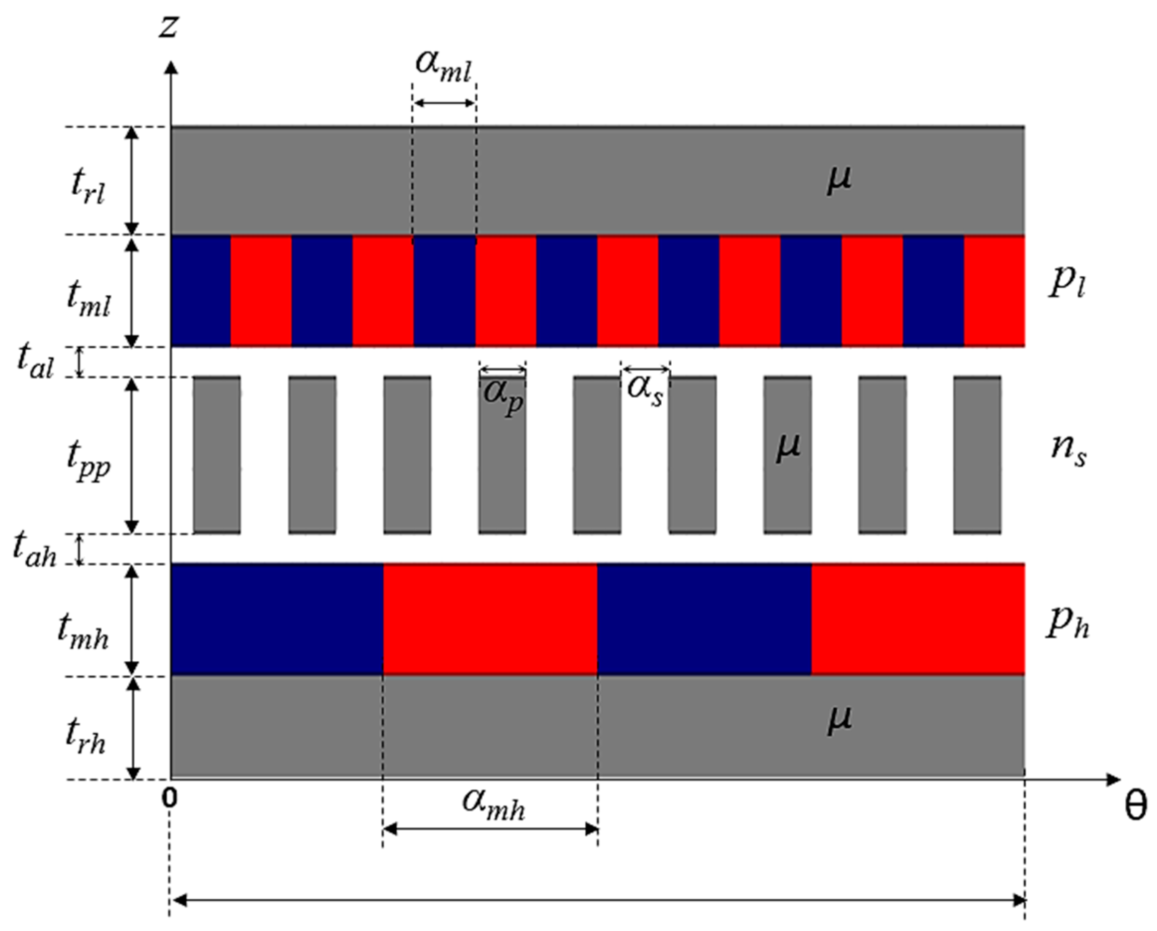
In addition to the advantages that MEC can have over FEM, such as moderate computational complexity and accuracy, the MEC method allows easy and quick access to the structure of the model to parameterize it in a way that is more in accordance with the design requirements. These attributes of the MEC can be used to study magnetic gears. In order to model the AFMG, a 2D model is proposed in this paper using the MEC method. According to [8], the AFMG is unrolling at the mean radius of the magnets. The resulting 2D model is shown in Figure 2.
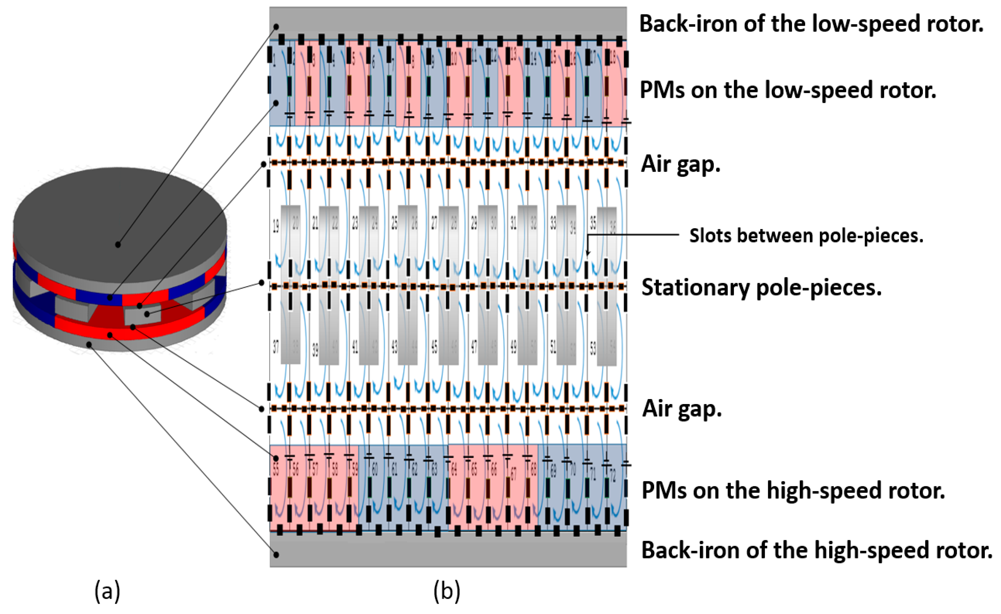
For the chosen configuration, i.e., pl = 7, ph = 2, and ns = 9, the AFMG is divided into seven layers in the axial direction (z) to take into account the different materials. The minimum repetitive unit in that direction, i.e., the ferromagnetic pole pieces, determines the number of divisions in the circumferential (θ) direction [26]. Each ferromagnetic pole piece and each slot between them is divided into an integer number of reluctance blocks. Hence, the accuracy of the results is proportional to the number of pole piece divisions. Figure 3 shows the RN representing the MEC of the AFMG. The model is based on flux mesh equations rather than nodal equations. Under non-linear operating conditions, the computational performance of the mesh-based MEC formulation is superior to that of the nodal-based formulation [27].
The mesh-based RN is the basis for the MEC formulation. The base geometry form for each reluctance element is a sector layer, where for 2D modeling, only the axial (z) and circumferential (θ) components are considered, as shown in Figure 4.
The 2D model formulation considers both the linear and non-linear behaviors in the reluctance elements to describe their magnetic nature according to the material they represent.
Linear reluctance elements are defined only by their geometries. They represent the permanent magnets, the air gaps, and the slots between the pole pieces in the modulator.
From the geometrical parameters in Figure 4, the values of which are shown in Table 1, the axial reluctances (Rz) and the circumferential reluctances (Rθ), respectively, are given by
R z = 2 L μ 0 μ r α r 0 2 - r i 2
and
R θ = α μ 0 μ r L ln r o r i

2.3. Considering Non-Linearity in Ferromagnetic Materials

Non-linear reluctance elements depend on both the geometry and the magnetic non-linearity of the BH curve, corresponding to the magnetic material. This dependency allows us to take into account the saturation of the magnetic material. These non-linear reluctances (Rm) represent the rotors’ yokes and the ferromagnetic pole pieces. They are expressed in terms of the magnetic flux (ϕ) and the parameters describing the relation between the magnetic field intensity (H) and the magnetic flux density (B) [14]:
R m ϕ = a 1 l A + a n l A n ϕ n - 1
where l and A are, respectively, the length of the magnetic path and the cross-sectional area of the element.
The parameters a1, an, and n, are the approximation coefficients of a polynomial function of order n, which has proved to be effective at representing the magnetic non-linear relation between H and B,
H B = a 1 B + a n B n
In (7), the first term represents the lineal condition (in fact, a1 is a reluctivity parameter), and the second term reflects the saturation effect (an is the non-linear parameter). The order n depends on the degree of saturation of the material and is determined by the material’s non-linearity [13]. For the material considered in this paper, a1 = 1.08 A·T−1·m−1, an = 0.02 A·T−13·m−1, and n = 13.
The sources are represented by the PMs, which are modeled by magnetomotive force (MMF) sources of a rectangle function. The MMF source of each PM (F) is defined by
F θ = - H c l z 2 π tan - 1 b sin p θ
where Hc is the coercive force of the magnet material, which is supposed to be the same for all of the PMs; lz is the magnetic path length in the axial direction, b is coefficient of the FMM function of the PM, and p is the number of pole pairs in the corresponding rotor.

3. System Solution

Once the reluctances have been classified and assigned to the different layers of the modeled structure, they are connected in a network to build the MEC. Nodal- and mesh-based ones are two alternative formulations to construct a matrix system of non-linear algebraic equations that mathematically model the MEC. Nodal- and mesh-based formulations have different numerical properties. Some works have shown that mesh-based ones have better convergence when a Newton–Raphson algorithm is used to solve the algebraic system [27].

3.1. Matrix System Assembly Using a Mesh-Based Formulation

The MEC-RN is represented by a non-linear algebraic equations system. For a mesh-based formulation, a system of mesh equations is established using the analog Kirchhoff’s voltage law (KVL) for the magnetic circuits. In this formulation, the magnetic reluctance relates the MMF to the magnetic flux flowing through the reluctance element according to Hopkinson’s law.
For some studies, the MEC model is a practical tool used to explore steady-state behavior in electromagnetic systems; the model is configured as a system of mesh equations, where the MMFs are inputs, and the mesh fluxes are outputs. On this basis, the overall system is defined in the following form:
R φ = F θ
where R is a symmetric matrix composed of the different reluctance elements, φ is the vector of mesh fluxes, and F is the vector of MMF sources which are functions of the rotor position, θ.

3.2. Solution of the Mesh-Based MEC Model

The non-linear algebraic equations of the MEC with lumped parameters are numerically solved using a Newton–Raphson algorithm. For such purposes, an iterative solution was implemented in an MATLAB program. The target is to calculate an updated vector of mesh fluxes. The flowchart describing the different steps of the steady-state model of the MEC-RN is shown in Figure 5.
To solve the system in (9), the overall solution procedure starts by establishing a set of initial conditions for the given positions of the rotors.
In the iterative solver, the first calculation is performed for the flux in each branch, computing the difference between the adjacent mesh fluxes,
Φ b r i = φ m _ c u r r i - φ m _ a d j i
where φ m _ c u r r i is the mesh flux in current mesh, and φ m _ a d j i is the mesh flux in the adjacent mesh.
The next calculation is the flux density in each branch, both in the axial and circumferential directions,
B b r = Φ b r A b r
where Bbr is the is the flux density the branch, Φbr is the flux through the branch, and Abr is the average cross-sectional area of the reluctance element, which is normal to the flux direction.
After that, the reluctances matrix, (R), is updated, considering the linear and non-linear elements according to Equations (4)–(6). Similarly, the Jacobian matrix, (J), is updated being formed by the set of linear reluctances and the partial derivatives of non-linear reluctances that are dependent on the flux, according to the Newton–Raphson formulation,
J = R + R φ m i , Φ φ m i
Then, the vector of the mesh fluxes is computed with the Newton–Raphson formula.
φ m i + 1 = φ m i - J φ m i - 1 R φ m i - F θ
The solution of this model required relatively few iterations, with no need for a relaxation factor.
The MMFs distribution of both rotors is given by (8). Finally, the electromagnetic torque for each rotor is computed using the next formula [13]:
τ = n θ 2 π k = 1 n θ Φ b r P M Δ F P M
where nθ is the number of rotor division in the circumferential direction, Φ b r P M is the flux at each branch of PMs, and FPM is the difference of MMFs in PMs according to (8).

4. Optimization and Validation of the MEC-RN Model

The optimization of electrical machines and electromagnetic devices, including magnetic gears, often comprises multiple objectives that must be considered simultaneously. From this, it follows that in a multi-objective optimization problem, there may not exist a best solution with respect to the set of defined objectives. Since there is no unique solution that is better than another one, any proposed solution can be considered as acceptable. Hence, it is convenient to have a precise knowledge of the nature of the problem to choose the most appropriate solution. Some studies establish an intelligent way to solve multi-objective problems [28,29]; they propose a transformation of the original problem into a single-objective one by weighting the objectives with a weight factor. Hence, for a multi-objective optimization problem, any single-objective optimization algorithm can be used, but with a solution dependent on the weight factor that is used in the weighting process. Although the optimization problem that has been developed in the investigation of this paper is of multi-objective nature, only the results related to the torque density maximization of the magnetic gear studied are reported. The purpose is to highlight the benefit of analyzing an AFMG with the combination of MEC-RN modeling and GA for an optimized design.

4.1. Genetic Algorithms

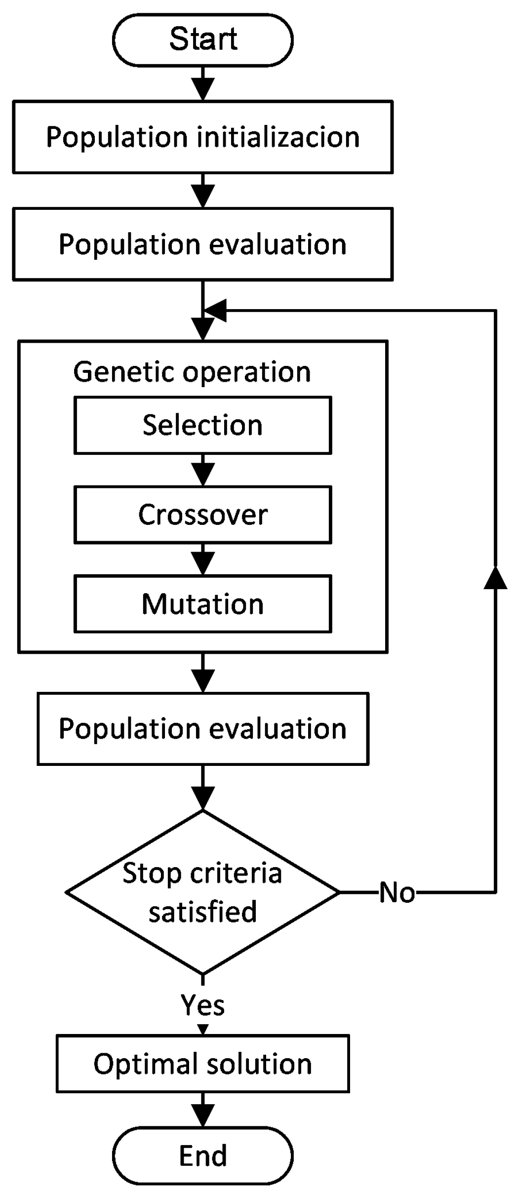
GAs have turned out to be adaptive intelligent algorithms for solving practical problems in engineering and science. Inspired by Darwin’s theory, they work as a stochastic search means, emulating biological evolutionary theories to solve optimization problems. These algorithms exhibit speed and robustness without the need to rigorously mathematically model the physical system. A prominent property defining GAs is that these algorithms work based on a population of points in a space known as the Pareto optimal front; this is extremely important since some objectives are often contradictory. The parallel search from a population of points avoids being stuck in a limited optimal solution. Figure 6 illustrates a general flowchart that explains the operation of GAs optimization.
According to [30], and as shown in Figure 6, the GA starts with a population that can be considered as all of the possible solutions for a given problem. Then, using an analogy with the human population, solutions from one population (known as a parent) are taken and used to form a new population (known as children or offspring). This is represented by a fitness function that takes a desired solution as the input, providing the suitability of this solution as an output. In some cases, it is the same as the objective function, while in others, it could be different. This action is carried out by three fundamental genetic operations: selection, crossover, and mutation. These operations actually alter the genetic composition of the new solutions related to the fitness function. In this scheme, solutions which are used to generate new solutions (children or offspring) are selected in terms of their fitness, which means that the more suitable they are, the more opportunities they have to reproduce in the evolutionary process [30,31].

4.2. Multi-Objective Function

In order to obtain an optimized model of the magnetic gear, a multi-objective cost function f(x) is defined based on the current design strategy using the MEC-RN and the advantages of the MOGA process. The multi-objective cost function is given by Equations (15)–(19).
min f ( x ) = f 1 x , f 2 x , f 3 x
s.t.
f 1 x = π r 0 2 l a x i a l
where
l a x i a l = t r l + t m l + t r h + t m h + t p p + 2 t a
f 2 x = τ l s - τ l s r a t e d
f 3 x = τ h s - τ h s r a t e d
x l x x u
where l a x i a l is the active axial length of the MG defined as a function of the thickness of its main components whose parameters are shown in Table 2. The three cost functions f1, f2, and f3 are related to the magnetic gear volume, low-speed magnetic gear torque, and high-speed magnetic gear torque, respectively. They are represented as normalized values in the optimization solution process. In the above equations, x is the design variable vector, whereas the subscripts l and u indicate the lower and upper bounds, respectively. τ r a t e d represents the rated magnetic gear torque.

4.3. Optimization Results

The AFMG parameters for the MEC configuration are shown in Table 1; these are the current values used by Lubin et al. in their original design [8]. To minimize the volume of the MG, which is equivalent to a torque density maximization, eight design variables were chosen. These variables are shown in Table 2, where the bound constraints imposed on each variable and the optimized values after applying the GA can be observed. The multi-objective optimization was executed using the following parameters: 800 generations, a population of 200, a tournament size of 2, a crossover fraction of 0.8, a crossover ratio of 1.0, a migration fraction of 0.2, and a Pareto front fraction of 0.35.
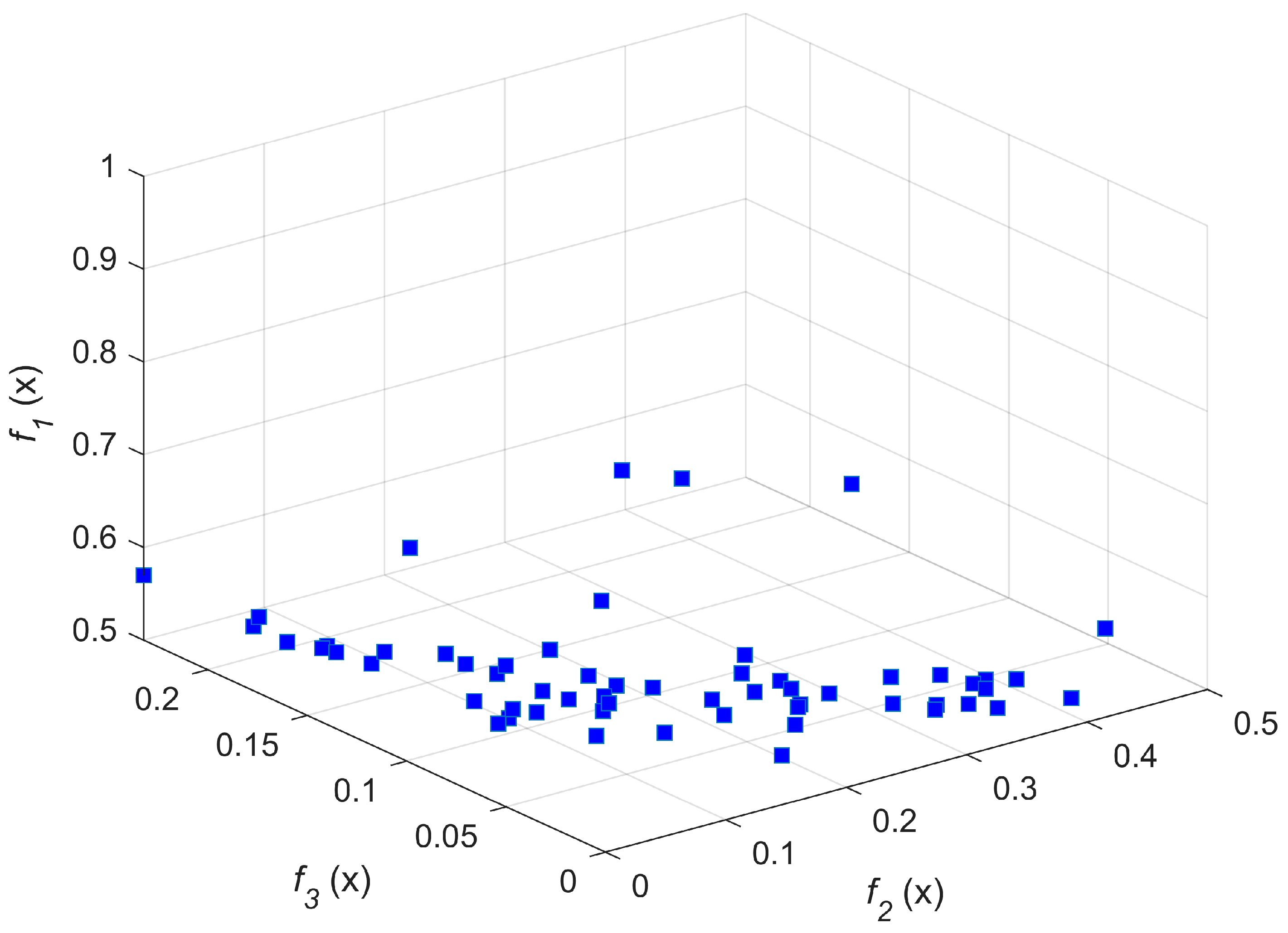
Figure 7 shows the Pareto front fraction of the objective functions considered in the optimization process. On this basis, the AFMG volume determined from the optimization process for the MEC-RN in this paper is 4.9632 × 10⁻⁴ m3, which is equivalent to a decrease that is close to 23.3% with respect to the model of Lubin et al. [8], which indicates an increase in the torque density of the same value.

5. MEC-RN Evaluation and Performance Analysis of the Optimized AFMG

In order to verify the performance of the optimized MEC-RN model, the results in MATLAB were compared to a 3D-FEA magnetostatic model created in the ANSYS Maxwell® version 17.0 finite element simulation software package. Both the models were based on the dimensions presented in Table 1, which were updated with the values of the design parameters determined during the optimization process using MOGA. With an MG configurated as a magnetic speed multiplier, the analysis focuses on the high-speed rotor, since the most pronounced effects occur on the load side, which is mainly due to cogging torque. The air gap flux density and the values of the torques generated in both of the rotors are investigated during the analyses. Related graphs and simulation results are shown below.
The 3D-FEA simulation is used to predict the best results in terms of the mesh balancing reliability. Figure 8 shows the mesh plot of the 3D-FEA magnetostatic model used for the comparison. The reasonableness of the grid division applied to the AFMG structure is based on using an acceptable level of the FE mesh discretization of the model, which can give good numerical results. To achieve a reasonably accurate solution, usually, thousands of FE nodes are needed. Hence, considerable computational effort is required to solve the FE equations that describe the system. The 3D finite element mesh of the studied MG has 206,397 elements. The mesh quality has enough elements to represent the MG regions to guarantee the accuracy of the numerical computation. In MEC, the nodes creating a mesh over the studied regions are connected to each other by reluctances. The reluctances represent the flux paths over the cross-section areas in the MG. In the MEC model, the mesh density is defined by setting the number of divisions in the circumferential direction. The basis of this division is the smallest circumferential repetitive unit represented by each pole piece of the modulator. Thereby, the pole pieces are divided equally into an integral number to increase the mesh density. However, too coarse meshes can lead to unreasonable results. For the proposed optimized MEC-RN model, acceptable results were obtained with 54 divisions in the circumferential direction, considering that each pole piece and the slots between them are divided equally into three parts. Therefore, the AFMG model was divided into 432 mesh elements.
The flux density distribution vectors and their directions are shown in Figure 9. Figure 9a illustrates the results from a 3D model, while Figure 9b is the representation of the flux density vectors in different regions of optimal AFMG from a 2D model. As seen in the figure, the flux direction indicates that opposite PMs are facing different poles.
Figure 10 shows the paths of flux density lines in a 2D model of the optimized AFMG. It is clear that the flux density is higher in close proximity to the MMF sources represented by the PMs. Figure 11 shows the calculated variation of the axial component of magnetic flux density in the middle height and radius of high-speed rotor air gap for the pl = 7 and ph = 2 configuration. In the plot, it can be found that the modulation of the ferromagnetic pole pieces on the magnetic field distribution in the air gap determined in the MEC-RN exhibits a close tendency to that which is presented by the 3D-FEM model. From these results, it can be considered that the complicated distribution of the magnetic flux density in the air gap can be predicted with acceptable accuracy by using an MEC-RN model.
To entirely satisfy the proposed objective function, the torques generated in both of the rotors were calculated. The results of the optimization of the MEC-RN model showed that for the high-speed rotor, the torque is 13.5962 Nm, while for the low-speed rotor, the torque is 47.3711 Nm. From these values, the Gr calculated by the MEC-RN optimized model is 3.484, which is quite consistent, as expected according to Equation (2).

6. Conclusions

In this paper, an optimal design method using MEC-RN modeling with an MOGA process has been presented to optimize and analyze the performance of an AFMG. The MEC modeling allows us to easily parameterize a reluctance network to represent different topologies of magnetic gears. Magnetic flux density has been calculated and compared to a 3D-FEA model. The results show a close agreement. This demonstrates that an MEC-RN model can predict the complicated distribution of the magnetic field density in the air gap when the parameterization of this model is compatible with the FEA model. The applied MOGA over MEC-RN resulted in an optimized geometry, with 23% decrease in volume and the same percentage of increase in torque in relation to the original geometry of Lubin et al. [8]. This work has allowed us to show that with the combination of an MEC-RN model and an MOGA for its optimization, a satisfactory accuracy can be achieved compared to that of FEA.

Author Contributions

Conceptualization, G.R.-P. and M.A.A.; methodology, G.R.-P. and M.A.A.; software, C.H. and M.A.A.; validation, G.R.-P., M.A.A. and C.H.; formal analysis, G.R.-P. and M.A.A.; investigation, G.R.-P. and M.A.A.; resources, M.A.A.; data curation, M.A.A.; writing—original draft preparation, G.R.-P.; writing—review and editing, G.R.-P. and M.A.A.; visualization, G.R.-P., M.A.A., C.H. and R.E.-P.; supervision, M.A.A.; project administration, G.R.-P. and M.A.A. All authors have read and agreed to the published version of the manuscript.

Funding

This research received no external funding.

Data Availability Statement

Not applicable.

Acknowledgments

The authors would like to thank La Laguna Institute of Technology (TNM) for the financial support to carry out this research.

Conflicts of Interest

The authors declare no conflict of interest.

References

  1. Jian, L.; Chau, K.T. Analytical Calculation of Magnetic Field Distribution in Coaxial Magnetic Gears. Prog. Electromagn. Res. 2009, 92, 1–16. [Google Scholar] [CrossRef]
  2. Li, X.; Chau, K.T.; Cheng, M.; Hua, W.; Du, Y. An improved coaxial magnetic gear using flux focusing. In Proceedings of the International Conference on Electrical Machines and Systems (ICEMS), Beijing, China, 20–23 August 2011; pp. 1–4. [Google Scholar]
  3. Gardner, M.C.; Jack, B.E.; Johnson, M.; Toliyat, H.A. Comparison of Surface Mounted Permanent Magnet Coaxial Radial Flux Magnetic Gears Independently Optimized for Volume, Cost, and Mass. IEEE Trans. Ind. Appl. 2018, 54, 2237–2245. [Google Scholar] [CrossRef]
  4. Desvaux, M.; Sire, S.; Hlioui, S.; Ben Ahmed, H.; Multon, B. Development of a Hybrid Analytical Model for a Fast Computation of Magnetic Losses and Optimization of Coaxial Magnetic Gears. IEEE Trans. Energy Convers. 2019, 34, 25–35. [Google Scholar] [CrossRef]
  5. Wang, J.; Qian, L.; Xu, S.; Mo, R. Analysis of Electromagnetic Performance of Modulated Coaxial Magnetic Gears Used in Semi-Direct Drive Wind Turbines. J. Ass. Energy Eng. 2021, 118, 251–264. [Google Scholar] [CrossRef]
  6. Zhu, D.; Yang, F.; Du, Y.; Xiao, F.; Ling, Z. An axial-field flux-modulated magnetic gear. IEEE Trans. Appl. Supercond. 2016, 26, 0604405. [Google Scholar] [CrossRef]
  7. Mezani, S.; Atallah, K.; Howe, D. A high-performance axial-field magnetic gear. J. Appl. Phys. 2006, 99, 08R303. [Google Scholar] [CrossRef]
  8. Lubin, T.; Mezani, S.; Rezzoug, A. Development of a 2-D analytical model for the electromagnetic computation of axial-field magnetic gears. IEEE Trans. Magn. 2013, 49, 5507–5521. [Google Scholar] [CrossRef]
  9. Zhou, T.; Huang, Y.; Dong, J.; Guo, B.; Zhang, L. Design and modeling of axial flux permanent magnet machine with yokeless and segment armature using magnetic equivalent circuit. In Proceedings of the 2014 17th International Conference on Electrical Machines and Systems (ICEMS), Hangzhou, China, 22–25 October 2014; pp. 618–623. [Google Scholar]
  10. Amrhein, M.; Krein, P.T. 3-D Magnetic Equivalent Circuit Framework for Modeling Electromechanical Devices. IEEE Trans. Energy Convers. 2009, 24, 397–405. [Google Scholar] [CrossRef]
  11. Fukuoka, M.; Nakamura, K.; Ichinokura, O. Dynamic analysis of planetary-type magnetic gear based on reluctance network analysis. IEEE Trans. Magn. 2011, 47, 2414–2417. [Google Scholar] [CrossRef]
  12. Holehouse, R.C.; Atallah, K.; Wang, J. A linear magnetic gear. In Proceedings of the 2012 XX International Conference on Electrical Machines (ICEM), Marseille, France, 2–5 September 2012; pp. 563–569. [Google Scholar]
  13. Fukuoka, M.; Nakamura, K.; Ichinokura, O. A method for optimizing the design of SPM type magnetic gear based on reluctance network analysis. In Proceedings of the 2012 XX International Conference on Electrical Machines (ICEM), Marseille, France, 2–5 September 2012; pp. 563–569. [Google Scholar]
  14. Fukuoka, M.; Nakamura, K.; Ichinokura, O. RNA-Based optimum design method for SPM type magnetic Gears. J. Magn. Soc. Jpn. 2013, 37, 264–267. [Google Scholar] [CrossRef] [Green Version]
  15. Wu, Y.-C.; Juan, B.-S. Magnetic field analysis of a coaxial magnetic gear mechanism by two-dimensional equivalent magnetic circuit network method and finite-element method. Appl. Math. Modell. 2015, 39, 5746–5758. [Google Scholar] [CrossRef]
  16. Thyroff, D.; Meier, S.; Hahn, I. Modeling integrated magnetic gears using a magnetic equivalent circuit. In Proceedings of the 2015 41st Annual Conference of the IEEE Industrial Electronics Society (IECON2015), Yokohama, Japan, 9–12 November 2015; pp. 002904–002908. [Google Scholar]
  17. Benlamine, R.; Hamiti, T.; Vangraefschèpe, F.; Dubas, F.; Lhotellier, D. Modeling of a coaxial magnetic gear equipped with surface mounted PMs using nonlinear adaptive magnetic equivalent circuits. In Proceedings of the 2016 XXII International Conference on Electrical Machines (ICEM), Lausanne, Switzerland, 4–7 September 2016; pp. 1888–1894. [Google Scholar]
  18. Feshki Farahani, H. Magnetic equivalent circuit modelling of coaxial magnetic gears considering non-linear magnetising curve. IET Sci. Meas. Technol. 2020, 14, 454–461. [Google Scholar] [CrossRef]
  19. Beirami, A.; Feshki Farahani, H.; Mohammad Rahimi, R.; Amini, S. Dynamic analysis of Halbach coaxial magnetic gears based on magnetic equivalent circuit modelling. IET Circuits Devices Syst. 2021, 15, 260–271. [Google Scholar] [CrossRef]
  20. Johnson, M.; Gardner, M.C.; Toliyat, H.A. A Parameterized Linear Magnetic Equivalent Circuit for Analysis and Design of Radial Flux Magnetic Gears—Part I: Implementation. IEEE Trans. Energy Convers. 2018, 33, 784–791. [Google Scholar] [CrossRef]
  21. Cavagnino, A.; Bramerdorfer, G.; Tapia, J.A. Optimization of electric machine designs-Part I. IEEE Trans. Ind. Electron. 2017, 64, 9716–9720. [Google Scholar] [CrossRef]
  22. Sepaseh, J.; Rostami, N.; Reza Feyzi, M.; Bannae Sharifian, M.B. Optimal design of an axial magnetic gear by using particle swarm optimisation method. IET Electr. Power Appl. 2022, 16, 723–735. [Google Scholar] [CrossRef]
  23. Atallah, K.; Calverley, S.D.; Howe, D. Design, analysis and realization of a high-performance magnetic gear. IEE Proc. Electric Power Appl. 2004, 151, 135–143. [Google Scholar] [CrossRef]
  24. Zhu, Z.Q.; Howe, D. Influence of design parameters on cogging torque in permanent magnet machines. IEEE Trans. Energy Convers. 2000, 15, 407–412. [Google Scholar] [CrossRef]
  25. Amrhein, M.; Krein, P.T. Induction machine modeling approach based on 3-D magnetic equivalent circuit framework. IEEE Trans. Energy Convers. 2010, 25, 339–347. [Google Scholar] [CrossRef]
  26. Perho, J. Reluctance Network for Analysing Induction Machines, Doctor of Science in Technology; Helsinki University of Technology: Espoo, Finland, 2002. [Google Scholar]
  27. Derbas, H.W.; Williams, J.M.; Koenig, A.C.; Pekarek, S.D. A comparison of nodal- and mesh-based magnetic circuit models. IEEE Trans. Energy Convers. 2009, 24, 388–396. [Google Scholar] [CrossRef] [Green Version]
  28. Dias, A.H.F.; Vasconcelos, J.A. Multiobjective Genetic Algorithms Applied to Solve Optimization Problems. IEEE Trans. Magn. 2002, 38, 1133–1136. [Google Scholar] [CrossRef]
  29. Osyczka, A. Multicriteria optimization for engineering design. In Design Optimization; Gero, J.S., Ed.; Academic Press, Inc.: Orlando, FL, USA, 1985; pp. 193–227. [Google Scholar]
  30. Lei, G.; Jianguo Zhu, J.; Youguang Guo, Y. Multidisciplinary Design Optimization Methods for Electrical Machines and Drive Systems; Springer: Berlin/Heidelberg, Germany, 2016; pp. 107–159. [Google Scholar]
  31. Kalyanmoy, D. Multi-Objective Optimization Using Evolutionary Algorithms; John Wiley & Sons, Ltd.: Chichester, UK, 2001. [Google Scholar]
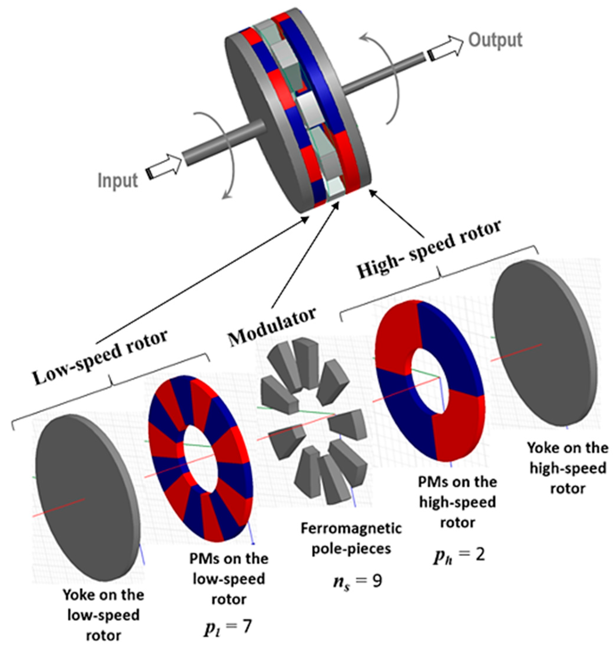
Figure 1. Topology of the AFMG.
Energies 16 01852 g001
Figure 2. Two-dimensional model of the AFMG.
Energies 16 01852 g002
Figure 3. Two-dimensional MEC-RN model of the AFMG: (a) structure; (b) RN configuration.
Energies 16 01852 g003
Figure 4. Geometry of a typical reluctance element. φz: axial flux; φθ: circumferential flux.
Energies 16 01852 g004
Figure 5. Flowchart of the overall procedure for MEC-RN solution.
Energies 16 01852 g005
Figure 6. Flowchart for general GAs.
Energies 16 01852 g006
Figure 7. Pareto front of the feasible optimal solutions.
Energies 16 01852 g007
Figure 8. The 3D-FEA magnetostatic model mesh plot of the AFMG.
Energies 16 01852 g008
Figure 9. Flux density distribution and its direction: (a) 3D model; (b) 2D model.
Energies 16 01852 g009
Figure 10. Magnetic flux lines path in a 2D AFMG model.
Energies 16 01852 g010
Figure 11. Axial flux density in the high-speed rotor air gap.
Energies 16 01852 g011
Table 1. Parameters of the AFMG *.
SymbolQuantityValue
plPole pair numbers of low-speed rotor7
phPole pair numbers of high-speed rotor2
nsNumber of ferromagnetic pole pieces9
GrGear ratio3.5
trlLow-speed rotor yoke thickness7 mm
tmlLow-speed rotor permanent magnet thickness7 mm
talAir gap near the low-speed rotor2 mm
tppLength of the ferromagnetic pole pieces10 mm
tahAir gap length near the high-speed rotor2 mm
tmhHigh-speed rotor permanent magnet thickness7 mm
trhHigh-speed rotor yoke thickness7 mm
riInner radius30 mm
roOuter radius70 mm
alPole-arc-to-pole-pitch ratio of low-speed PMs1
ahPole-arc-t- pole-pitch ratio of high-speed PMs1
αmlWidth of the low-speed rotor permanent magnet0.4488 rad
αmhWidth of the high-speed rotor permanent magnet1.5708 rad
αsSlot opening0.3491 rad
αpWidth of the ferromagnetic pole piece0.3491 rad
BrRemanence of the magnets1.25 T
HcCoercive force−995 kA/m
* Based on [8].
Table 2. Optimum design variables.
Design VariableLower Bound (mm)Upper Bound (mm)Optimum Value (mm)
roGear outer radius (x1)507159.49
riGear inner radius (x2)203127.56
trlLow-speed rotor yoke thickness (x3)6126.62
tmlLow-speed PM thickness (x4)6128.55
tppFerromagnetic pole pieces thickness (x5)91511.2
tmhHigh-speed PM thickness (x6)6127.51
trhHigh-speed rotor yoke thickness (x7)6126.97
taAir gaps length (x8)141.85
Disclaimer/Publisher’s Note: The statements, opinions and data contained in all publications are solely those of the individual author(s) and contributor(s) and not of MDPI and/or the editor(s). MDPI and/or the editor(s) disclaim responsibility for any injury to people or property resulting from any ideas, methods, instructions or products referred to in the content.