Article

Investigation of the Properties of Anode Electrodes for Lithium–Ion Batteries Manufactured Using Cu, and Si-Coated Carbon Nanowall Materials

1
Department of Electrical Engineering, Hanbat National University, Daejeon 34158, Republic of Korea
2
Department of Chemical and Biological Engineering, Hanbat National University, Daejeon 34158, Republic of Korea
3
Department of Advanced Materials Science and Engineering, Hanbat National University, Daejeon 34158, Republic of Korea
*
Author to whom correspondence should be addressed.
Energies 2023, 16(4), 1935; https://doi.org/10.3390/en16041935
Submission received: 12 January 2023 / Revised: 3 February 2023 / Accepted: 14 February 2023 / Published: 15 February 2023
(This article belongs to the Section D2: Electrochem: Batteries, Fuel Cells, Capacitors)

Abstract

:
The fabrication of high-capacity, binder-free Li–ion battery anodes using a simple and efficient manufacturing process was reported in this research. The anode material for lithium–ion batteries utilized is a combination of two-dimensional (2D) carbon nanowalls (CNWs) and Cu nanoparticles (improved rate performance and capacity retention) or Si (high capacity) nanoparticles. A methane (CH4) and hydrogen (H2) gas mixture was employed to synthesize CNWs on copper foil through microwave plasma-enhanced chemical vapor deposition (PECVD). The Cu or Si nanoparticles were then deposited on the CNW surface using an RF magnetron sputtering equipment with four-inch targets. To analyze the electrochemical performance of the LIBs, CR2032 coin-type cells were fabricated using anode materials based on CNWs and other components. It was confirmed that the Cu−CNW demonstrates improved rate performance, increased specific capacity, and capacity retention compared with traditional anodes. Additionally, CNW combined with Si nanoparticles has enhanced the capacity of LIB and minimized volume changes during LIB operation.

1. Introduction

Over the past 20 years, considerable attention has been paid to the use of lithium–ion batteries (LIBs) as one of the most alluring energy storage devices [1,2]. A lithium–ion battery’s working capacity depends on the constant flow of lithium ions from the anode to the cathode and vice versa. The movement of lithium ions during discharge causes an electrical current to flow from the cathode to the anode. During charging, the ions move back to the cathode in a reversed process. The electrolyte facilitates the movement of ions and prevents direct contact between the electrodes, avoiding a short circuit in the battery (Figure 1) [3,4]. To further enhance LIB performance, an essential and urgent step in the process is to maximize the energy and power density of LIB for the development and manufacture of anode electrode materials with their outstanding specific capacity and efficiency durability [5,6].
Although among the carbon-based materials, the CNTs have been shown to be potential anode material candidates for providing LIBs with high reversible capacitance, there are still significant restrictions before applying CNTs in commercial products [7,8,9]. It is interesting to observe that simple adjustments to the synthesis process lead to the production of carbon nanowalls (CNWs) instead of CNTs [10]. Carbon nanowalls possess a distinctive structure with vertically developed graphene walls, which offer excellent electrical conductivity, and quickly moving electrons because of their massive graphene surface area [11,12,13,14]. The latest research also reveals that reversible capacities for carbon nanowalls can extend from 300 to 700 mAhg−1. Unfortunately, as carbon nanowall materials were just recently discovered, commercial CNW anodes currently available on the market have several drawbacks, including a limited theoretical Li storage capacity and the detrimental impacts of having metallic lithium plated on the anode [15,16]. The methods of manufacturing CNWs with the appropriate structures in terms of diameters, layers, lengths, degrees of defects, and electrical properties have not yet been sufficiently optimized.
Currently, the research and technical development field have paid a great deal of attention to Si as an anode material in lithium secondary batteries due to its extraordinarily high storage ability theoretically (4200 mAhg−1) [17,18,19]. However, two significant problems restrict the full operation of Si anodes and prevent the commercial usage of Si powder. Firstly, silicon has a poorer conductivity, which makes it challenging for the current collector to draw current. Secondly, silicon experiences a significant change of up to 300% during the alloying and de-alloying reaction with Li+ ions [20,21,22]. The volume expansion of silicon can result in a constant generation and destruction of the solid electrolyte interface (SEI) layer, which consumes a lot of electrolytes. The creation of a stress buffer system not only supports lowering the agglomeration problem but also considerably lowers the volume effect of Si materials, thereby increasing electrochemical performance as nano-silicon is mixed with other conductive active materials [23,24]. As a result, composite anodes of CNWs and an amount of Si have also been identified as a good option since Si can significantly boost the capacity of LIBs, while the flexible CNWs matrix can efficiently release the stress on by the volume change of Si during the charge and discharge process, prevent direct contact of the Si surface with the electrolyte, and offer highways for the movement of electron and Li+ [25,26].
Numerous studies have discovered using copper (Cu) coatings on graphite materials can suppress volume expansion and increase electronic conductivity for anode materials of LIBs. Theoretically, sputtered copper films would support net electrode conductivity while offering good adherence to the electrode material [27,28,29]. In addition, reduced electrode volume expansion and contraction can be expected during battery cycling. Nanoscale copper particles were uniformly and compactly coated on the surface of carbon nanowalls to help lessen the co-intercalation of soluble lithium–ion. The Cu coating minimizes direct contact between the active surface of the graphite carbon and the solid electrolyte interface (SEI) membrane [30,31,32,33]. In conclusion, the Cu–coated graphene carbon performs better than the original graphene carbon in terms of electrochemical performance and anode material cycling. The overall effectiveness of battery cycling would be enhanced.
The lithium storage capacity of electrode materials is extremely reliant on manufacturing methods. It is worth mentioning that employing the plasma-enhanced chemical vapor deposition (PECVD) approach to manufacturing CNWs has a number of advantages over the chemical vapor deposition method. Through the development of the plasma sheath, the plasma generates an electric field that can efficiently direct CNW growth toward the substrate surface, resulting in the development of vertically oriented CNW structures [34,35,36]. Through special, electric-field-driven polarization effects, the diffusion barriers of nucleation might well be decreased, increasing the growth and nucleation speeds. By increasing the temperature through plasma exposure, the procedure allows for effective customization of the shape, diameter, and crystallinity of CNWs [37,38,39,40]. Additionally, sputtering is a widely utilized technique to deposit different materials in the material industry. Its demand for a low substrate temperature is one of its benefits, making it an attractive selection in many applications. In theory, the sputtering film should provide high adhesion to the electrode material while promoting pure electrical conductivity [32,41,42]. In this study, we focus on a few state-of-the-art methods for fabricating materials for high-performance LIBs. A graphene-based anode electrode was made using a plasma-enhanced chemical vapor deposition system at standard pressure and gas flow rate, with CNWs created in place of CNTs. The RF magnetron sputtering is then chosen as a production technique for the deposition of nanoparticles because highly energy radioactive particles (Cu and Si, in this instance) are released from a firmly attached film.

2. Experimental Details

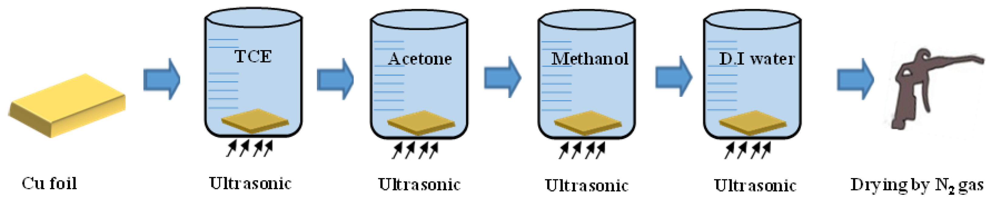
2.1. Preparing Substrate and Carbon Nanowall Growth

The schematic diagram of the cleaning procedure for the Cu foil used as the current collector in a lithium–ion battery is shown in Figure 2. To remove the foreign substances, the copper foil was washed separately in an ultrasonic cleaner and then dried using nitrogen (N2) gas. The CNW was grown on Cu foil using plasma-enhanced chemical vapor deposition (PECVD) (Figure 3a). During this stage, the carbon nanowall (CNWs) were synthesized for twenty minutes, with the pressure inside the chamber maintained at a vacuum state of 5 × 10⁻⁵ Torr. A reaction gas mixture composed of hydrogen and methane (H2/CH4 = 2:1) was introduced into the chamber of Microwave PECVD. The temperature and power of Microwave PECVD were 550 °C and 1200 W, respectively. The internal vacuum of the chamber was 4 × 10⁻² Torr during the synthesis of CNWs. After the synthesis, the chamber was cooled to below room temperature. Table 1 shows the conditions for growing the CNW via PECVD.

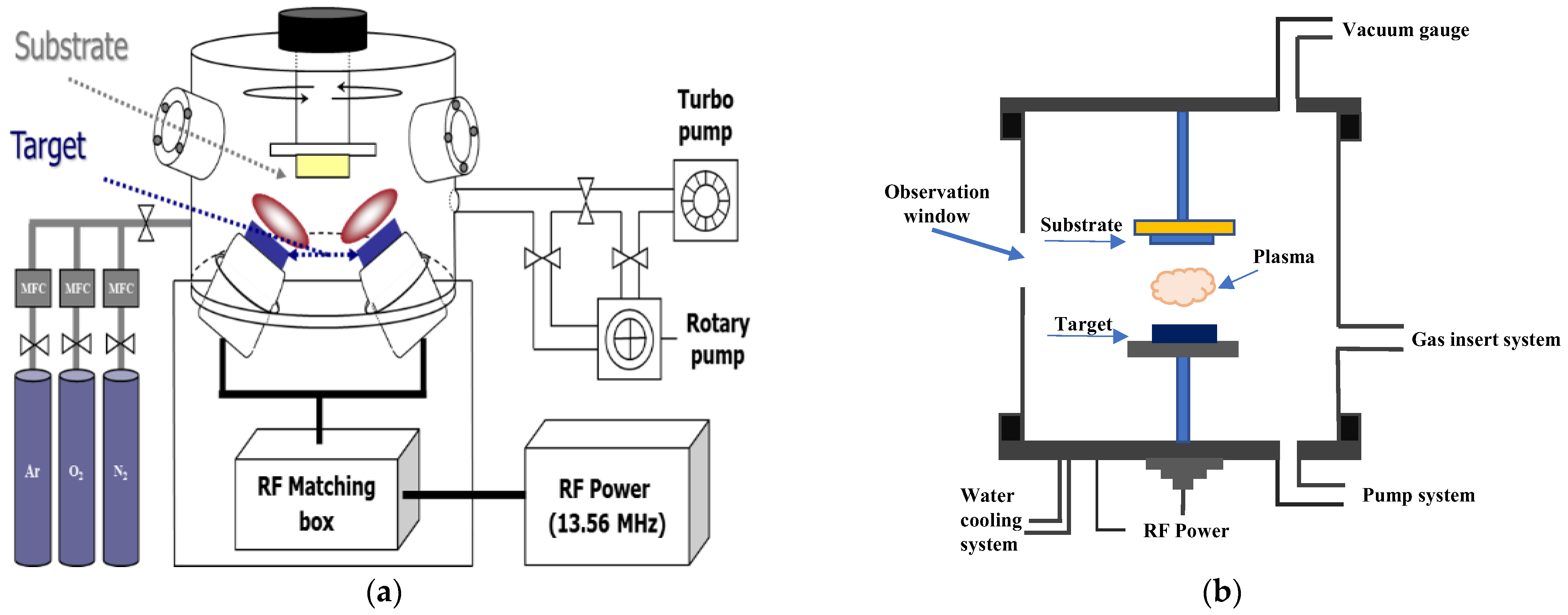
2.2. Preparation of Substrate and Carbon Nanowall Growth

The CNWs were then placed in a radio frequency (RF) magnetron sputtering system (Figure 3b) chamber with a base vacuum maintained below 10−5 Torr. Argon gas was introduced as the sputtering gas at a rate of 40 standard cubic centimeters per minute, and the pressure inside the chamber was kept at 3 × 10⁻³ Torr during the process. Cu target was sputtered for 10 min, while the Si target was sputtered for 25 min at 100 W RF power and 1.0 × 10⁻² Torr working vacuum. The detailed deposition conditions for the Cu and Si targets are shown in Table 2.

2.3. Fabrication of Lithium–Ion Battery

The coin cell (CR2032, Wlcos, Gunpo, Republic of Korea) was manufactured in a glove box filled with argon gas VAC (Vacuum Atmosphere Cooperation, H2O < 1 ppm, O2 < 0.1 ppm). The working electrodes were layer-coated CNWs, while the counter electrode was lithium metal with a thickness of 150 m. All coin cells employed polyethylene (Celgard, 20 m, Daejeon, Republic of Korea) as the separator and 1 M LiPF6 (Panax Etec, Daejeon, Republic of Korea) as the electrolyte in EC/DMC = 4/6 (v/v). The specific capacities were determined based on the weight of graphene, Cu, and Si materials. The average weight of CNW, Cu−CNW, and Si−CNW materials was 0.021 g, 0.026 g, and 0.023 g, respectively. Figure 4 displays the schematic diagram of the coin cell’s construction and assembly.

2.4. Analysis and Measurement

In this study, field emission scanning electron microscopy (FE-SEM, Hitachi S-4800), energy-dispersive spectroscopy (EDS, Hitachi S-4800), and Raman spectrometry (micro-Raman Spectrometer, FEX, Seongnam, Republic of Korea) were performed to analyze the structural characteristic of the anode materials. To analyze the electrochemical properties, lithium–ion batteries are fabricated with anode materials of carbon-based materials. Impedance analysis (PGSTAT, Autolab, Daejeon, Republic of Korea), cyclic voltammetry (CV, WizECM-1200, Daejeon, Republic of Korea), and galvanostatic charge–discharge test (SC, PNE solution, Daejeon, Republic of Korea)) were performed for the fabricated lithium–ion batteries, respectively. Impedance analysis is intended to measure the resistance of the ion movement path from the copper foil to the electrolyte of the manufactured lithium–ion batteries. The cyclic voltage current method is a method of analysis designed to observe whether an oxidation reaction and a reduction occur when charging and discharging a lithium–ion battery. The constant current charging and discharging test is a means to measure stability and capacity retention by repeatedly charging and discharging for many cycles.

3. Results and Discussion

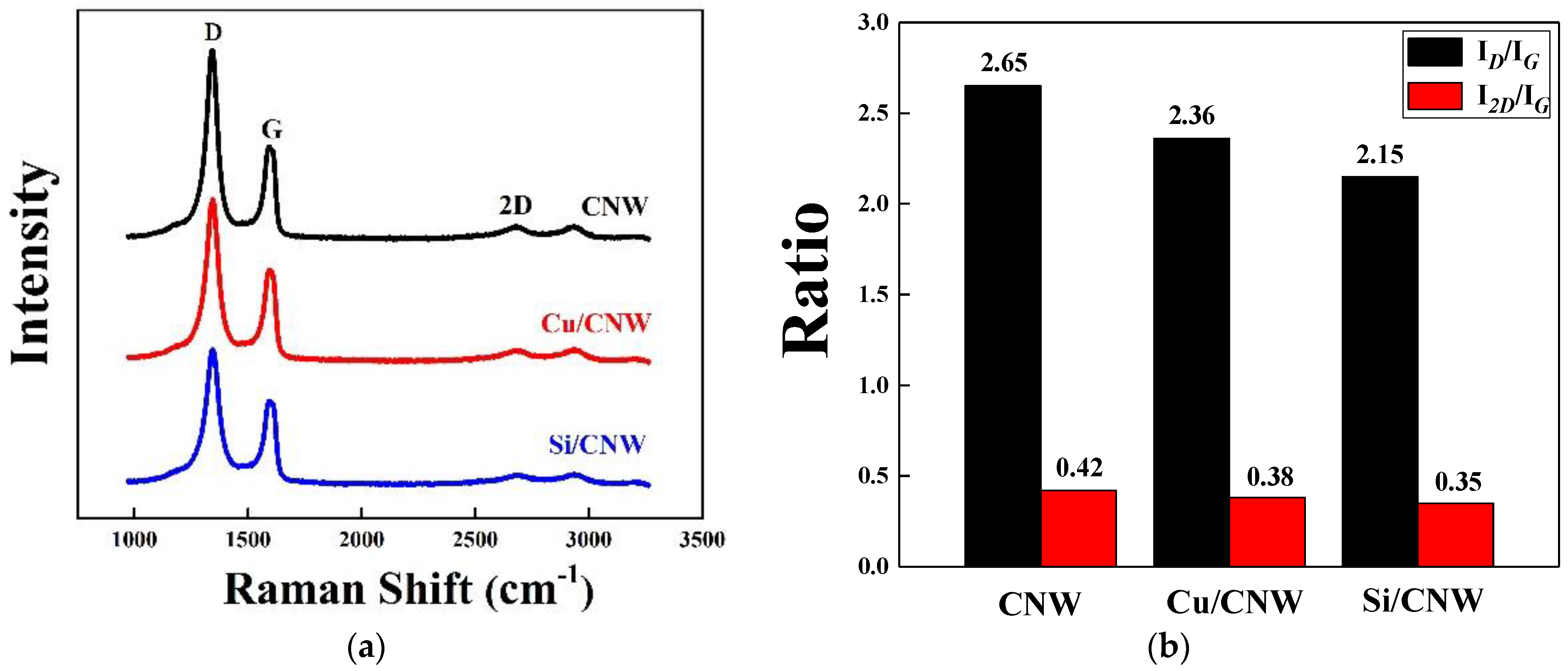
3.1. Morphology and Microstructure of the Synthesized Anode Materials

To establish a good CNW surface for uniform distribution of Cu and Si nanoparticles across the CNW matrix, the proper duration, power, and temperature must be determined. Following a comprehensive analysis of the morphology, microstructure, and electrochemical performance of the CNWs produced under distinct conditions, we came to the decision that the CNW sample manufactured using PECVD equipment at 550 °C for 20 min has the optimal morphology and microstructure.
In Figure 5a1,b1,c1, the as-synthesized CNWs were grown into uniform shapes and to heights of about 1.8 µm on Cu substrates. The carbon nanowall (CNWs) formed a thin single layer with a distinctive labyrinthine structure, and the two-dimensional carbon layers were robustly grown upright on the substrates. It deserves to be highlighted that the homogeneous distribution of the CNW surface layer results in a buffer matrix that is important for the insertion and extraction of lithium ions.
In Figure 5b1,b2, when copper and silicon nanoparticles were deposited on CNWs surface, the morphology and structure of the CNWs were well maintained. Both sides of the CNWs were uniform and smooth, and did not have any observable agglomeration. Since the coated films are extremely thin, it is challenging to confirm the thickness of the sputtered copper coating on the CNW surface through FE-SEM measurement. However, the walls of the CNWs were thickened as a result of the particles penetrating all samples to a depth of around 0.6 µm from the CNW surfaces. This suggests that the CNWs thickened when a significant amount of copper was deposited at their ends.
Figure 5c1,c2 shows the FE-SEM images of the Si-coated CNWs at RF power 100 W and 25 min of deposition time. The Si nanoparticles entered the CNWs surface at a depth of approximately 0.6 µm, indicating a similar trend to those of the Cu nanoparticles. However, due to the effect of different deposition rates as well as the differences in the thermal conductivity of Cu and Si on substrates with the Si coating, this is deemed to indicate that the CNW surface was coated with a smaller particle volume, resulting in thinner walls than that of the Cu−CNWs.
Owing to the uniform distribution of all Cu and Si nanoparticles in the CNW matrices and the considerable volume of Cu and Si that was synthesized at the ends of the CNWs, a buffer for the insertion and extraction of lithium ions was established.
For further investigation, EDS analyses were carried out to verify the elements and the component ratios of the carbon-based anode materials. As can be seen from Table 3, the results regarding the main element of the anode electrode were found to be carbon, Cu, and Si without impurities. The EDS results of the Cu-sputtered anodes showed the existence of both carbon and copper. The weight percentage of carbon was 87.64 and its atomic percentage was 97.39, while the weight percentage of copper was 12.36 and its atomic percentage was 2.61. These results confirmed that the silicon component was the least present, with a weight percentage of 8 and an atomic percentage of 1.62. Meanwhile, the weight percentage of carbon was 92 and its atomic percentage was 98, although the deposition time of Si is more extended than that of Cu. This might be a consequence of the influence of different deposition rates, as explained and proven by the FE-SEM results.
Raman analysis was conducted to examine the structural characteristics of the CNW samples, and the results are summarized in Figure 6a. In this study, the D peak, G peak, and 2D peak were confirmed in all the samples. The strong D peak that was seen at 1343–1345 cm−1 was a result of the defects in the CNWs, such as distortions, vacancies, and grain boundaries, which were caused by the high edge density of the nanowall. The presence of the G peak, which is a characteristic of graphene and commonly seen in carbon materials, was observed at 1575–1577 cm−1. Additionally, the 2D peak is due to a second-order process that can be identified as observed at 2688–2694 cm−1, and its appearance confirms that CNWs have successfully grown on the Cu foil [43,44].
In contrast to CNW with sputtered copper or sputtered silicon nanoparticles, the D peak of CNWs was measured with a particularly strong intensity. The bonding of the CNW with Cu or Si particles appears to have diminished the wall-shaped structure of the CNW, and the silicon material that was deposited appears to be a mixture of nanocrystalline and phases. A characteristic feature of CNW is that the D peak was larger than the G peak due to the presence of defects and sp3 hybridized carbon bonding in the nanostructure. In addition, the size and shape of carbon nanowalls, with their high aspect ratio and large surface area, can also contribute to the increased intensity of the D peak. An appropriate Si nanomaterial might provide extra benefits for the creation of next-generation LIB anode materials because the nanocrystal phase adds nanolayer stability to the material.
Figure 6b shows the ID/IG ratios expressing the defect levels of the samples and the I2D/IG ratios representing the number of graphene layers [40]. Moreover, a lower ID/IG ratio indicates superior crystal quality and fewer defects [45,46,47]. Among the samples, the ID/IG ratio of the CNW was the highest, while that of the Si−CNW was the lowest. This indicates that the CNWs deposited with nano Si−particles had the most outstanding crystal quality and the fewest defects. On the other hand, this result suggests that lattice screws and scattering during the formation of carbon nanowalls have proceeded more than CNW growth with Cu or Si deposition. It is believed that the defects were reduced due to the effect of the additional Cu and Si particles.

3.2. Electrochemical Performance of Cu, Si-Coated CNWs Based LIBs

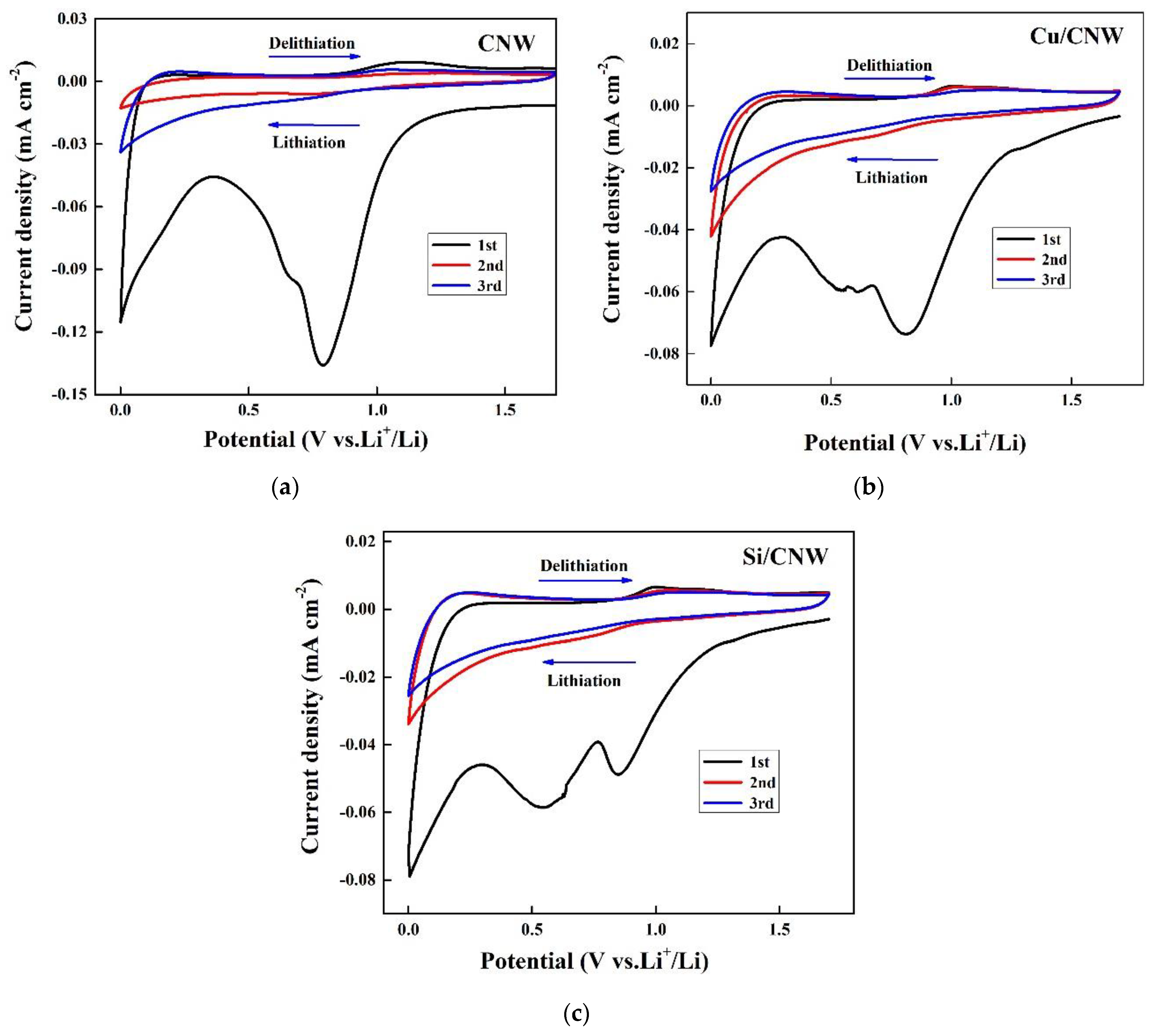
  • Cyclic voltammetry of lithium–ion batteries
Figure 7 shows specific capacities obtained during the initial three charge and discharge cycles of manufactured LIBs. The CV was measured within a voltage window of 0~1.7 V and the scan rate was 0.1 mV/s for the 12th cycle. Figure 7a shows the three reduction peaks at ∼0.77 V, ∼0.58 V, and ∼0.01 V. Figure 7b shows three reduction peaks at ∼0.77 V, ∼0.54 V, and ∼0.01 V, while Figure 7c shows the two reduction peaks at ∼0.77 V, and ∼0.01 V. From the CV graph, we can notice that reduction peaks appear in the cathodic scan of the 1st cycle and disappear completely in the following cycles. The strong cathodic peak at ∼0.77 V resulted from the irreversible decomposition of the electrolyte at the electrode surface and the subsequent creation of the solid electrolyte interphase (SEI). After the initial discharge, the thin, stable SEI coating might prevent direct contact electrode from direct contact with the electrolyte, protecting the electrode’s structural integrity. When oxidation occurs, a second cathodic peak at a lower voltage (∼0.01 V) coexists with an anodic peak at ∼0.17 V. This redox pair is persistent and reversible over subsequent cycles. Furthermore, the first cycle of Figure 7c shows a reduction peak at approximately 0.58 V, which is due to the creation of LiC6 and LixSi alloy as a result of Li insertion into graphene and amorphous/nanocrystalline Si.
The oxidation peak represents the charging process of the LIB when lithiation happens in the anode materials. The cyclic voltammetry (CV) graph of CNW is displayed in Figure 7a, which shows two oxidation peaks at approximately 1.1 V and 0.17 V. Figure 7b depicts the CV graph of Cu−CNW, with two oxidation peaks at approximately 0.9 V and 0.17 V. Similarly, Figure 7c represents the CV graph of Si−CNW, featuring two oxidation peaks at approximately 1.0 V and 0.17 V. The increase in the oxidation peak indicates an increase in specific capacity and long-term stability during the charging process and is observed in Figure 7b,c. Additionally, the intensity of the current peaks increases as the cycle proceeds, and this result can be related to the increased activation of the anode materials. However, comparing the CVs for the LIBs based on Cu−CNW, Si−CNW, and CNW, the CV graph of CNW does not show the increment in the oxidation peaks. As we can see from the CVs of the LIBs based on CNW in Figure 7a, the strength of the oxidation peak gradually diminishes as the number of cycles rises, indicating a weaker Li extraction kinetics. According to the above results, Si and CNWs in the composite material support Li+ ion insertion and extraction.
  • Impedance analysis of lithium–ion batteries
EIS measurement was utilized to obtain the typical Nyquist plot to better comprehend the electrode kinetics of LIBs based on CNW. Published papers indicate that the charge-transfer impedance at the electrode/electrolyte interface is the cause of the semicircle in the high-frequency region, while the semicircle in the medium-frequency region is attributed to the SEI film and/or contact resistance. The inclined line at roughly a 45° angle to the real axis represents the lithium diffusion process within the carbon electrodes [48,49,50]. Figure 8 shows that all of the samples have a semicircle in the high-frequency region and an approximately straight line in the low-frequency region, which is a typical Nyquist curve. There is no significant difference in electrolyte resistance (Re) because the same electrolyte is used. Based on these Nyquist plots, the CNW electrode showed the highest RSEI value compared to those of the Cu−CNW and Si−CNW electrodes due to the largest interaction between the electrode and electrolyte, SEI on the CNW electrode surface becoming the thickest. On the contrary, for the Cu−CNW electrode, the diameter of the semicircle has the lowest RSEI value. This result supports our analysis that the addition of Cu nanoparticles can reduce ion diffusion distance and increase reaction electrochemical kinetics, resulting in better anode electrochemical performance. It has been demonstrated that sputtered copper (Cu) coatings on CNW materials improve electronic conductivity.
In LIBs based on Cu−CNW and Si−CNW, the semicircular diameter of the negative electrode coated with Si nanoparticles is smaller than that of the negative electrode coated with Cu nanoparticles in the high-frequency region, indicating that the electrode coated with Si has a lower charge transfer resistance. However, the presence of Si nanoparticles can improve the speed and smoothness of the diffusion of lithium ions and electrons from the copper foil to the electrolyte. Finally, Figure 8 illustrates electrochemical impedance spectroscopy (EIS) to explain the excellent enhancement of Cu and Si-doped graphene anode in battery performance.
  • Charge–discharge behavior of lithium–ion batteries
The galvanostatic charge/discharge (GCD) profiles of the three electrodes are presented in Figure 9a–c. The charge and discharge tests were performed up to a total of 100 cycles, with a voltage range of 0 to 1.5 V, and a fixed rate at 0.1 C in the first cycle, 0.2 C in the second cycle, and 0.5 C in the subsequent cycles. As shown in Figure 9, the voltage plateau at about 0.7 V in the first charge curve does not appear in the following cycles. For all samples, this might be the result of solid electrolyte interface (SEI) layer formation and electrolyte deterioration. However, after the second cycle, the charge/discharge curves started to slope without any evident plateaus. The charge/discharge curves nearly merge with the corresponding earlier ones after 50 cycles (except the first discharge curve). This remarkable result demonstrates that the generated SEI layer is stable and that the CNW anode material exhibits exceptional stability after the first cycle.
In addition, it can be observed in Figure 9d that the first charge and discharge capacities of Si−CNW and Cu−CNW are 779 mA h/g and 480 mA h/g, respectively, which are much larger than those of CNW at 443 mA h/g. The corresponding Coulombic efficiencies are 26%, 24%, and 18%. The Coulombic efficiency of electrodes based on CNW is relatively low in the initial cycle, which is a common occurrence for carbon electrodes with a large surface area. Moreover, these observations indicate that SEI formation on the copper, silicon-sputtered CNW composite anodes is much slower than on the original CNW electrode, which indicates that these electrodes have higher coulombic efficiency and less irreversible capacity than the CNW anode. It is also significant to mention that the amount of Li+ ions required to create the SEI is directly correlated with the area of direct contact between the electrode and the electrolyte. These findings suggest that the formation of the SEI layer consumes a significant amount of Li+ ions, reflecting the primary cause of the irreversible capacity loss in the first cycle. The lithium–ion/electron diffusion can be accelerated by the high surface area and unique architecture, which can greatly reduce the diffusion length and result in improved recyclability. It is worthwhile to mention that among all the anodes, the electrode coated by Cu nanoparticles exhibits the highest coulombic efficiency in most of the cycles. This is because the copper that has been covered with graphene prevents the tiny amount of exposed silicon from making contact with the electrolyte and instead creates a stable SEI layer that reduces irreversible capacity loss. Cu−CNW exhibits electrochemical stability findings with greater coulombic efficiency when compared to the CNW anode. These results also provide evidence that loading CNW with silicon boosts solid electrolyte stability, reduces silicon volume expansion, and improves electrochemical performance. The presence of a small amount of Si nanoparticle significantly improves specific capacity as well as the Coulombic efficiency of LIBs based on CNW.

4. Conclusions and Future Work

In this study, the CNW and layer-coated CNWs are prepared as anode materials to investigate the properties of LIBs. FE-SEM, EDS analysis, and Raman spectroscopy were performed to investigate the surface and cross−section structure as well as the structural characteristics of carbon−based materials fabricated for anode material. To analyze the electrochemical performance, lithium–ion batteries are fabricated with anode materials of carbon-based materials. Impedance analysis, cyclic voltammetry, and galvanostatic charge–discharge tests were performed for fabricated lithium–ion batteries, respectively. Based on these results, we have successfully designed nanostructured carbon material-based anode, namely CNWs, with a stable structure, considerable specific surface area, flexibility, and enhanced conductivity. Carbon nanowalls have been demonstrated to be very efficient buffers and can function as the structural core of nanostructured anode materials because they prevent the structural integrity degradation that frequently results from the substantial volume fluctuations brought on by charging and discharging. Furthermore, in these nanostructured anode materials, increased electron transport is provided by highly conductive carbon nanowalls. Owing to the uniform distribution of all Cu and Si nanoparticles in the graphite matrices and the considerable volume of Cu and Si that was synthesized at the ends of the CNWs, a buffer for the insertion and extraction of lithium ions can be established. The synthesized CNW can reduce defects occurring in the wall structure of CNW with the presence of Cu and Si nanoparticles. CNW also offers the advantage of storing many lithium ions in a small mass. The characteristics and electrochemical performance of high-energy LIBs were also found to be enhanced by copper, or silicon nanoparticles sputtered on carbon-based materials.
According to our research, Si−CNW is the best material for boosting structural stability, which enhances anode electrochemical properties. This result also reflected that, given its superior conductivity and compatibility with CNW, it is reasonable to assume that a composite Cu−CNW system would enhance anode conductivity, flexibility, and bonding to Cu current collectors, making it a promising option for practical, long-lasting anodes. The Si and Cu contents on carbon nanowalls can have a significant impact on the electrochemical performance of lithium–ion batteries because an excessive Cu and Si coating will prevent lithium–ion movement. Further research is needed to fully understand the relationship between the Si and Cu contents and the electrochemical performance of lithium–ion batteries, as well as the optimal amount of Si and Cu to use for specific applications. Moreover, it is crucial to pick the right fabrication parameters to manufacture CNWs with the right characteristics, such as proper structure, diameter, thickness, length, and minimal defects, as well as the necessary number of Cu and Si nanoparticles.

Author Contributions

M.T.T.: Conceptualization, Investigation, Writing—original draft. C.K. and S.K.: Methodology, Formal analysis. H.K., J.M.K. and J.K.: Writing—review and editing, Supervision. W.C.: Writing—review and editing, Supervision, Funding acquisition. All authors have read and agreed to the published version of the manuscript.

Funding

This work was supported by the Korea Institute of Energy Technology Evaluation and Planning(KETEP), the Ministry of Trade, Industry & Energy(MOTIE) of the Republic of Korea (No. 20204030200080), and the National Research Foundation of Korea(NRF) grant funded by the Korea government(MSIT) (No. 2022R1A2C1009709).

Institutional Review Board Statement

Not applicable.

Informed Consent Statement

Not applicable.

Data Availability Statement

No data were used for the research described in the article.

Conflicts of Interest

The authors declare no conflict of interest.

References

  1. Nitta, N.; Wu, F.; Lee, J.T.; Yushin, G. Li-ion battery materials: Present and future. Mater. Today 2015, 18, 252–264. [Google Scholar] [CrossRef]
  2. Chen, Y.; Kang, Y.; Zhao, Y.; Wang, L.; Liu, J.; Li, Y.; Liang, Z.; He, X.; Li, X.; Tavajohi, N.; et al. A review of lithium-ion battery safety concerns: The issues, strategies, and testing standards. J. Energy Chem. 2021, 59, 83–99. [Google Scholar] [CrossRef]
  3. Nzereogu, P.U.; Omah, A.D.; Ezema, F.I.; Iwuoha, E.I.; Nwanya, A.C. Anode materials for lithium-ion batteries: A review. Appl. Surf. Sci. Adv. 2022, 9, 100233. [Google Scholar] [CrossRef]
  4. Pargoletti, E.; Arnaboldi, S.; Cappelletti, G.; Longhi, M.; Meroni, D.; Minguzzi, A.; Mussini, P.R.; Rondinini, S.; Vertova, A. Smart interfaces in Li-ion batteries: Near-future key challenges. Electrochim. Acta 2022, 415, 140258. [Google Scholar] [CrossRef]
  5. Mageto, T.; Bhoyate, S.D.; de Souza, F.M.; Mensah-Darkwa, K.; Kumar, A.; Gupta, R.K. Developing practical solid-state rechargeable Li-ion batteries: Concepts, challenges, and improvement strategies. J. Energy Storage 2022, 55, 105688. [Google Scholar] [CrossRef]
  6. Zhang, L.; Zhu, C.; Yu, S.; Ge, D.; Zhou, H. Status and challenges facing representative anode materials for rechargeable lithium batteries. J. Energy Chem. 2022, 66, 260–294. [Google Scholar] [CrossRef]
  7. Zhao, F.; Zhao, M.; Dong, Y.; Ma, L.; Zhang, Y.; Niu, S.; Wei, L. Facile preparation of micron-sized silicon-graphite-carbon composite as anode material for high-performance lithium-ion batteries. Powder Technol. 2022, 404, 117455. [Google Scholar] [CrossRef]
  8. Lim, S.Y. Amorphous-silicon nanoshell on artificial graphite composite as the anode for lithium-ion battery. Solid State Sci. 2019, 93, 24–30. [Google Scholar] [CrossRef]
  9. Wang, Q.; Yang, H.; Meng, T.; Yang, J.; Huang, B.; Gu, F.L.; Zhang, S.; Meng, C.; Tong, Y. Boosting electron transfer with heterointerface effect for high-performance lithium-ion storage. Energy Storage Mater. 2021, 36, 365–375. [Google Scholar] [CrossRef]
  10. Tran Thi, M.; Lee, S.; Choi, W. Adhesion and stability increased carbon nanowall for the application to lithium-ion batteries. J. Electr. Eng. Technol. 2022, 17, 3613–3618. [Google Scholar] [CrossRef]
  11. Kim, S.Y.; Choi, W.S.; Lee, J.H.; Hong, B. Substrate temperature effect on the growth of carbon nanowalls synthesized via microwave PECVD. Mater. Res. Bull. 2014, 58, 112–116. [Google Scholar] [CrossRef]
  12. Höltig, M.; Ruhmlieb, C.; Strelow, C.; Kipp, T.; Mews, A. Synthesis of carbon nanowalls and few-layer graphene sheets on transparent conductive substrates. Z. Phys. Chem. 2015, 229, 301–316. [Google Scholar] [CrossRef] [Green Version]
  13. Tran Thi, M.; Kwon, S.; Kang, H.; Kim, J.H.; Yoon, Y.K.; Choi, W. Growth properties of carbon nanowalls on nickel and titanium interlayers. Molecules 2022, 27, 406. [Google Scholar] [CrossRef]
  14. Yu, K.; Bo, Z.; Lu, G.; Mao, S.; Cui, S.; Zhu, Y.; Chen, X.; Ruoff, R.S.; Chen, J. Growth of carbon nanowalls at atmospheric pressure for one-step gas sensor fabrication. Nanoscale Res. Lett. 2011, 6, 202. [Google Scholar] [CrossRef] [PubMed] [Green Version]
  15. Mumlyakov, A.M.; Shibalov, M.V.; Timofeeva, E.R.; Trofimov, I.V.; Porokhov, N.V.; Evlashin, S.A.; Nekludova, P.A.; Pershina, E.A.; Anufriev, Y.V.; Tagachenkov, A.M.; et al. Fabrication and characterization of quasi-three-dimensional capacitor structure based on carbon nanowalls. Carbon 2021, 184, 698–705. [Google Scholar] [CrossRef]
  16. Choi, H.; Kwon, S.; Kang, H.; Kim, J.H.; Choi, W. Adhesion-increased carbon nanowalls for the electrodes of energy storage systems. Energies 2019, 12, 4759. [Google Scholar] [CrossRef] [Green Version]
  17. Liu, H.; Sun, Q.; Zhang, H.; Cheng, J.; Li, Y.; Zeng, Z.; Zhang, S.; Xu, X.; Ji, F.; Li, D.; et al. The application road of silicon-based anode in lithium-ion batteries: From liquid electrolyte to solid-state electrolyte. Energy Storage Mater. 2023, 55, 244–263. [Google Scholar] [CrossRef]
  18. Silicon and Silicon–Copper Composite Nanorods for Anodes of Li-Ion Rechargeable Batteries—Tìm Trên Google. Available online: https://www.google.com/search?q=Silicon+and+silicon–copper+composite+nanorods+for+anodes+of+Li-ion+rechargeable+batteries.&oq=Silicon+and+silicon–copper+composite+nanorods+for+anodes+of+Li-ion+rechargeable+batteries.&aqs=chrome.0.69i59.610j0j4&sourceid=ch (accessed on 27 December 2022).
  19. Yang, Z.; Dong, Y.; Liu, C.; Feng, X.; Jin, H.; Ma, X.; Ding, F.; Li, B.; Bai, L.; Ouyang, Y.; et al. Design and synthesis of high-silicon silicon suboxide nanowires by radio-frequency thermal plasma for high-performance lithium-ion battery anodes. Appl. Surf. Sci. 2023, 614, 156235. [Google Scholar] [CrossRef]
  20. Wang, Q.; Meng, T.; Li, Y.; Yang, J.; Huang, B.; Ou, S.; Meng, C.; Zhang, S.; Tong, Y. Consecutive chemical bonds reconstructing surface structure of silicon anode for high-performance lithium-ion battery. Energy Storage Mater. 2021, 39, 354–364. [Google Scholar] [CrossRef]
  21. Ou, J.; Li, B.; Deng, H.; Li, K.; Wang, H. A carbon-covered silicon material modified by phytic acid with 3D conductive network as anode for lithium-ion batteries. Adv. Powder Technol. 2023, 34, 103891. [Google Scholar] [CrossRef]
  22. Hsu, Y.C.; Hsieh, C.C.; Liu, W.R. Synthesis of double core-shell carbon/silicon/graphite composite anode materials for lithium-ion batteries. Surf. Coat. Technol. 2020, 387, 125528. [Google Scholar] [CrossRef]
  23. Uxa, D.; Jerliu, B.; Hüger, E.; Dörrer, L.; Horisberger, M.; Stahn, J.; Schmidt, H. On the lithiation mechanism of amorphous silicon electrodes in li-ion batteries. J. Phys. Chem. C 2019, 123, 22027–22039. [Google Scholar] [CrossRef]
  24. Tan, Y.; Wang, K. Silicon-based anode materials applied in high specific energy lithium-ion batteries: A review. Wuji Cailiao Xuebao/J. Inorg. Mater. 2019, 34, 349–357. [Google Scholar] [CrossRef]
  25. Schmidt, H.; Jerliu, B.; Hüger, E.; Stahn, J. Volume expansion of amorphous silicon electrodes during potentiostatic lithiation of Li-ion batteries. Electrochem. Commun. 2020, 115, 106738. [Google Scholar] [CrossRef]
  26. Roiban, L.; Koneti, S.; Wada, T.; Kato, H.; Cadete Santos Aires, F.J.; Curelea, S.; Epicier, T.; Maire, E. Three dimensional analysis of nanoporous silicon particles for Li-ion batteries. Mater. Charact. 2017, 124, 165–170. [Google Scholar] [CrossRef]
  27. Au, M.; He, Y.; Zhao, Y.; Ghassemi, H.; Yassar, R.S.; Garcia-Diaz, B.; Adams, T. Silicon and silicon-copper composite nanorods for anodes of Li-ion rechargeable batteries. J. Power Sources 2011, 196, 9640–9647. [Google Scholar] [CrossRef]
  28. Gao, J.; Fu, L.J.; Zhang, H.P.; Zhang, T.; Wu, Y.P.; Wu, H.Q. Suppression of PC decomposition at the surface of graphitic carbon by Cu coating. Electrochem. Commun. 2006, 8, 1726–1730. [Google Scholar] [CrossRef]
  29. Nobili, F.; Dsoke, S.; Mancini, M.; Tossici, R.; Marassi, R. Electrochemical investigation of polarization phenomena and intercalation kinetics of oxidized graphite electrodes coated with evaporated metal layers. J. Power Sources 2008, 180, 845–851. [Google Scholar] [CrossRef]
  30. Wang, Q.; Zhang, Y.; Jiang, H.; Li, X.; Cheng, Y.; Meng, C. Designed mesoporous hollow sphere architecture metal (Mn, Co, Ni) silicate: A potential electrode material for flexible all solid-state asymmetric supercapacitor. Chem. Eng. J. 2019, 362, 818–829. [Google Scholar] [CrossRef]
  31. Nguyen, C.C.; Song, S.W. Characterization of SEI layer formed on high performance Si-Cu anode in ionic liquid battery electrolyte. Electrochem. Commun. 2010, 12, 1593–1595. [Google Scholar] [CrossRef]
  32. Yen, J.P.; Chang, C.C.; Lin, Y.R.; Shen, S.T.; Hong, J.L. Sputtered copper coating on silicon/graphite composite anode for lithium ion batteries. J. Alloys Compd. 2014, 598, 184–190. [Google Scholar] [CrossRef]
  33. Koike, S.; Fujieda, T.; Sakai, T.; Higuchi, S. Characterization of sputtered vanadium oxide films for lithium batteries. J. Power Sources 1999, 81–82, 581–584. [Google Scholar] [CrossRef]
  34. Cui, L.; Chen, J.; Yang, B.; Sun, D.; Jiao, T. RF-PECVD synthesis of carbon nanowalls and their field emission properties. Appl. Surf. Sci. 2015, 357, 1–7. [Google Scholar] [CrossRef]
  35. Mori, S.; Ueno, T.; Suzuki, M. Synthesis of carbon nanowalls by plasma-enhanced chemical vapor deposition in a CO/H2 microwave discharge system. Diam. Relat. Mater. 2011, 20, 1129–1132. [Google Scholar] [CrossRef]
  36. Gao, J.M.; Song, X.F.; Hu, J.; Guo, S.C.; Fang, L.; Wu, F.; Wei, D.P. Superhydrophobic graphenic carbon nanowalls fabricated by one-step PECVD. Mater. Lett. 2016, 184, 273–277. [Google Scholar] [CrossRef]
  37. Lee, S.; Choi, W.S.; Yoo, J.; Lim, D.G.; Kim, H.J.; Lee, J.H.; Hong, B. Fabrication of metal-coated carbon nanowalls synthesized by microwave plasma enhanced chemical vapor deposition. J. Nanosci. Nanotechnol. 2014, 14, 9189–9193. [Google Scholar] [CrossRef]
  38. Lee, S.; Kwon, S.; Kim, K.; Kang, H.; Ko, J.M.; Choi, W. Preparation of carbon nanowall and carbon nanotube for anode material of lithium-ion battery. Molecules 2021, 26, 6950. [Google Scholar] [CrossRef]
  39. Kwon, S.; Choi, H.; Lee, S.; Lee, G.; Kim, Y.; Choi, W.; Kang, H. Room temperature gas sensor application of carbon nanowalls using electrical resistance change by surface adsorption of toxic gases. Mater. Res. Bull. 2021, 141, 111377. [Google Scholar] [CrossRef]
  40. Kwon, S.H.; Kim, H.J.; Choi, W.S.; Kang, H. Structural and electrical characteristics of carbon nanowalls synthesized on the polyimide film. J. Nanosci. Nanotechnol. 2018, 18, 6309–6311. [Google Scholar] [CrossRef]
  41. Bhasin, V.; Nayak, C.; Biswas, A.; Halankar, K.K.; Tokas, R.B.; Ghosh, S.K.; Bahadur, J.; Bhattacharyya, D. Remarkably high capacity Li ion batteries with rf sputter deposited TiO2 thin film anodes on SS substrates. Appl. Surf. Sci. 2022, 592, 153273. [Google Scholar] [CrossRef]
  42. Liao, C.L.; Wu, M.T.; Yen, J.H.; Leu, I.C.; Fung, K.Z. Preparation of RF-sputtered lithium cobalt oxide nanorods by using porous anodic alumina (PAA) template. J. Alloys Compd. 2006, 414, 302–309. [Google Scholar] [CrossRef]
  43. Choi, H.; Choi, C.; Kwon, S.H.; Park, Y.; Choi, W. Characteristics of Carbon Nanowalls According to the Indium Tin Oxide Interlayer Thickness. Sci. Adv. Mater. 2020, 12, 1261–1264. [Google Scholar] [CrossRef]
  44. Ferrari, A.C. Raman spectroscopy of graphene and graphite: Disorder, electron-phonon coupling, doping and nonadiabatic effects. Solid State Commun. 2007, 143, 47–57. [Google Scholar] [CrossRef]
  45. Kim, C.; Kim, K.; Kwon, S.; Kang, H.; Hong, B.; Choi, W. Innovative variation in the morphological characteristics of carbon nanowalls grown on a molybdenum disulfide interlayer. Nanomaterials 2022, 12, 4334. [Google Scholar] [CrossRef] [PubMed]
  46. Park, J.K.; Shin, S.K.; Kim, H.; Joung, Y.H.; Kang, H.; Kim, J.H.; Kim, H.J.; Choi, W.S. Properties of carbon nanowalls grown on glass substrates according to the etching microwave power. J. Nanosci. Nanotechnol. 2016, 16, 10740–10743. [Google Scholar] [CrossRef]
  47. Kwon, S.; Choi, H.; Choi, W.; Kang, H. Wettability of CNW/ITO micro structure for modification of surface hydrophilicity. Appl. Sci. 2020, 10, 142. [Google Scholar] [CrossRef] [Green Version]
  48. Tröltzsch, U.; Kanoun, O.; Tränkler, H.R. Characterizing aging effects of lithium ion batteries by impedance spectroscopy. Electrochim. Acta 2006, 51, 1664–1672. [Google Scholar] [CrossRef]
  49. Singh, P.; Vinjamuri, R.; Wang, X.; Reisner, D. Fuzzy logic modeling of EIS measurements on lithium-ion batteries. Electrochim. Acta 2006, 51, 1673–1679. [Google Scholar] [CrossRef]
  50. Xie, Y.; Li, J.; Yuan, C. Mathematical modeling of the electrochemical impedance spectroscopy in lithium ion battery cycling. Electrochim. Acta 2014, 127, 266–275. [Google Scholar] [CrossRef]
Figure 1. A schematic diagram showing how a lithium–ion battery works.
Energies 16 01935 g001
Figure 2. Schematic diagram of the Cu foil cleaning.
Energies 16 01935 g002
Figure 3. Schematic of (a) the PECVD and (b) RF magnetron sputtering system.
Energies 16 01935 g003
Figure 4. Schematic diagram of the structure and assembly of a coin cell.
Energies 16 01935 g004
Figure 5. FE-SEM surface image of (a1) CNW, (b1) Cu−CNW, and (c1) Si−CNW; and FE-SEM cross-section image of (a2) CNW, (b2) Cu−CNW, and (c2) Si−CNW.
Energies 16 01935 g005
Figure 6. (a) Raman shift of the CNW, Cu−CNW, and Si−CNW, (b) ID/IG; and I2D/IG ratio of CNW, layer−coated CNWs from Raman shift.
Energies 16 01935 g006
Figure 7. CV graphs of (a) CNW, (b) Cu−CNW, and (c) Si−CNW for 1, 2, and 3 cycles.
Energies 16 01935 g007
Figure 8. Impedance spectra of LIBs based on CNW, Cu−CNW, and Si−CNW.
Energies 16 01935 g008
Figure 9. Charging and discharging profiles of LIBs based on CNW (a), Cu−CNW (b), Si−CNW (c), and Cycling performance of LIBs based on CNW, Cu−CNW, and Si−CNW (d).
Energies 16 01935 g009
Table 1. Conditions for growing CNW via PECVD.
SubstrateBase PressureWorking PressureChamber AtmosphereTemperatureGrowth Time
Cu foil5 × 105 Torr4 × 102 TorrH2:CH4 = 2:1550 °C20 min
Table 2. Conditions of deposition of Cu and Si layers via RF sputtering.
TargetCuSi
RF power100 W100 W
Base pressure1 × 10−5 Torr1 × 10−5 Torr
Working pressure3 × 10−3 Torr3 × 10−3 Torr
Sputtering gasAr: 40 sccmAr: 40 sccm
Rotation speed1700 rph1700 rph
Deposition time10 min25 min
Deposition temperatureRoom temperatureRoom temperature
Table 3. The element ratio of Cu and Si-coated CNWs samples.
SampleWeight %Atomic %
Cu/CNWCCuCCu
87.6412.3697.392.61
Si/CNWCSiCSi
928981.62
Disclaimer/Publisher’s Note: The statements, opinions and data contained in all publications are solely those of the individual author(s) and contributor(s) and not of MDPI and/or the editor(s). MDPI and/or the editor(s) disclaim responsibility for any injury to people or property resulting from any ideas, methods, instructions or products referred to in the content.

