1. Introduction
Pneumatic motors are widely used in the robotic, automation, and automotive industries. Compared to electric motors, a pneumatic motor has the benefits of large payload-to-weight and payload-to-volume ratios, and high speed and force capabilities [
1,
2,
3,
4,
5,
6]. By using an air motor to provide rotary actuation instead of electric motors in robotic actuators, they receive high power-to-weight and power-to-size ratios, good compliance, and resistance to environmental hazards [
1]. A hybrid pneumatic combustion engine also enhances the fuel economy by recovering wasted energy during engine braking [
2,
3]. A pneumatic engine is capable of storing energy in the form of compressed air in combustion engines to save 30% fuel consumption in small combustion engines [
4,
5]. Pneumatic motors are compact and lightweight. A pneumatic motor also has adjustable torque by regulating inlet gas pressure, and there is no overheating problem. Moreover, to avoid electricity usage, pneumatic motors can work under explosive and volatile atmospheres [
7].
A significant shift towards renewable energy has been the primary focus of many areas and countries in the last decade. New applications for pneumatic motors such as small-scale expanders have been fit in effective exhaust or cooling systems such as the organic Rankine cycle and Kalina cycle [
8,
9] because heat-driven power generation process is exceptionally effective at low-temperature heat conversion. Waste-heat recovery has been a recent implementation and yields more efficient energy conversion that, in turn, decreases harmful pollution emissions on a large scale. A similarly structured machine is also used as an expander in the power generation system of the organic Rankine cycle (ORC) and energy storage system of compressed air energy storage [
10], which is a vital component for system performance.
Different types of pneumatic motors (or gas expanders) are available, including the scroll [
11], screw [
12], piston [
13] and vane [
14] types. Pneumatic radial piston motor has advantages over the commonly used rotary vane-type motor: higher efficiency, torque, and power output. Bianchi et al. [
15,
16] used a radial piston expander with three cylinders placed at 120
that shared a crankshaft in their ORC system. The expander and connected generator generated 250–1200 W of electricity with a constant total efficiency of around 40%. Two semiempirical models of a radial piston expander were compared and used for more comprehensive unexplored operational conditions; the results indicated that the lumped parameters model had better accuracy than that of a polynomial fitting model. Han et al. [
17] tested a radial piston expander with five cylinders in an ORC system; the results showed the highest isentropic efficiency of 64.8% and the highest mechanical efficiency of 51.0%. Fukuta et al. [
18], and Ferrara et al. [
19] used a radial piston expander in CO
refrigeration systems to conduct work recovery by replacing the throttling valve. The former study achieved mechanical efficiency of 50–60% and overall expander efficiency of about 40%. The measured total efficiency of the used expander in the latter study was 19%, which increased the refrigeration cycle’s efficiency by 7.4%.
Although there are several researchs don on modelling of compression and compressors [
20], the modelling and simulation of a radial piston motor/expander have rarely been reported. In this study, a commercial pneumatic radial piston motor was modelled and experimentally tested. Volume equation, heat transfer correlation, thermodynamic energy conservation equation, and motion equation were linked to the simulation of the rotation of this motor. One of the crucial parameters of the motor, the overall friction coefficient, was used to simplify the modelling; however, its value was unknown and impossible to obtain through the calculations.
This article aims to model a radial pneumatic piston motor. Previous studies were carefully considered because of the lack of similarities shared between small-scale expanders. The technology for the pneumatic radial piston motor is exceptionally recent. However, using the ORC and Kalina cycle’s highest-rated expanders opens up a wide range of resources. Experimental results are fitted into functions to support the accuracy of the simulation. Using the same method as that developed in [
21] for scroll expander modelling and simulation, we fed the experimental results into the simulation to determine the value of this coefficient and obtain an accurate simulation that could be used to numerically study the system performance within a broader range of operational conditions, and guide the further design and optimisation of such motors/expanders. This allows for the additional exploration of the geometrical model and its performance. The expander is first geometrically and thermodynamically described, followed by stabilising the whole model and simulation. The experimental results are presented to give further insight into parameters that are tough to test or measure, such as the overall system friction factor, and to validate the simulation.
2. Working Principle
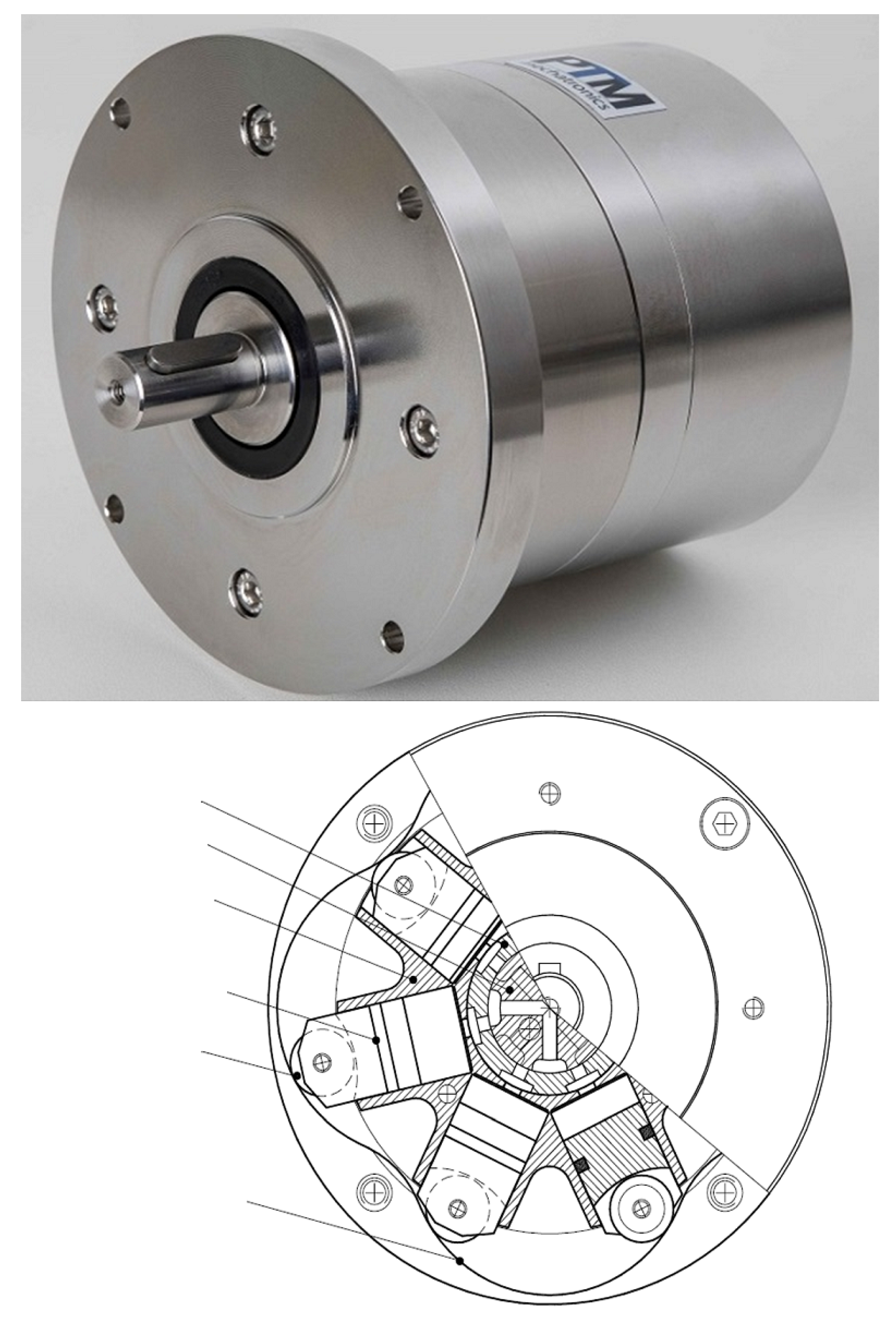
The pneumatic radial piston motor used in this study was supplied by PTM Mechatronics (model no.: PTM3600 VA G3 B1 Ex S) (
https://ptm-mechatronics.com/en/products/compressed-air-motors/stainless-steel-motor/), and its photo and interior structure are shown in
Figure 1. It has an innovative design of seven pistons in a star pattern moving along an inner curved piston guide. Sustainable efficiency could be achieved with high torque at minimal gas intake, low rotational speed, and reversible rotating direction. It also operates without piston rods or a crankshaft and has a long service life with little maintenance, in addition to instantaneous stop-and-starts with a high starting torque. In manipulating the inlet gas pressure, each piston cylinder uses a single valve to compress, expand, intake, and discharge the working gas. The motor works without a crankshaft or piston rods, has a 1:2 gear ratio, its rotational speed is between 60 and 600 rpm, with minimal and maximal torques of 1.5 and 16 Nm, respectively. The motor could generate maximal power of about 250 W. The application temperature range of the working gas was from −10 to 80
C. The operating pressure was in the range of 2–8 bar.
The motor has seven piston cylinders arranged in a star pattern. Each piston is connected to a guide roller at the bottom, allowing for the piston to glide along the curved inner surface of the housing. High-pressure gas enters the motor through the fixed piston control shaft via the floating piston control ring to individual pistons. The motor has four cross-arranged inlets and four cross-arranged outlets, as shown in
Figure 1. When it rotates, the working gas in the piston cylinders changes between charge and discharge.
During rotation, three of the seven piston cylinders are primarily responsible for generating a positive torque for rotation. The pressure difference between the working gas and back (ambient) pressure generates the force exerted at the contact point of the roller and guide curve along the direction from the motor centre to the roller centre (the normal direction of the piston), as shown in
Figure 2. This force can be divided into two component forces: one drives rotation, while the other presses perpendicularly on the glide surface, which generates friction.
2.1. Geometric Description of the Expander
Before modelling, the primary issue is to geometrically understand the piston motor. The detailed geometric information was obtained by analysing the cross-section, drawn as given in
Figure 1. The motor manufacturer gave the housing diameter (2R
) and the distance from the motor centre to the upper surface of the piston cylinder (R
). On the basis of the available R1, other dimensional parameters were proportionally calculated, as illustrated in
Figure 3. The calculated values are presented in
Table 1. The method was reliable, as there was only a minor error when comparing the calculated R4 and the value provided by the motor manufacturer.
The unique piston glide curve leads to complicated geometric calculations for the piston cylinder, which encompasses cycle segments with two different diameters, one concave with a larger radius R
, and the other convex with a smaller radius R
. Locating the centres of these circular segments and knowing their diameters are essential for understanding the rotation of pistons. Knowing the positions of the joint points of circle segments is also crucial. This study set the rotational angle at 0
when the piston cylinder was at the position shown in
Figure 3, and the rotation was clockwise. A critical rotational angle,
, is defined as the angle when the roller transits from gliding on the concave circle to the convex circle, as shown in
Figure 4a. The following equations were used to calculate
:
When rotational angle
satisfies i
/2 −
≤
≤ i
/2 +
, where (i = 0, 1, 2, 3), the piston roller glides along the concave circle curve as shown in
Figure 4b; otherwise, the roller glides along the convex circle curve as shown in
Figure 4c. The length from the motor centre to the piston roller centre L4 in
Figure 4 is the critical parameter to calculate the interior volume of the piston cylinder. Equations (6) and (7) were used to calculate L4 in
Figure 4b, and Equations (8) to (10) were used to calculate L
in
Figure 4c.
Volumetric change in the piston cylinder could be calculated from 0 to
/4, mirrored from
/4 to
/2, and the same variation can be repeated to 2
at every
/4. Once
is known, the interior volume of a single piston cylinder can be determined by calculating the following equation:
The result is presented in
Figure 5; one piston experienced 4 times the gas charge and discharge in each motor rotation.
2.2. Thermodynamic Model
The process inside the pneumatic motor follows the first thermodynamic law in an open control volume, as given in the following equation.
where
m is the mass of the gas inside the control volume,
u is the specific internal energy,
is the heat transferred from the surroundings to the gas inside the cylinder,
P is the gas pressure,
V is the gas volume,
t is the time,
is the inlet gas mass flow rate,
is the inlet gas enthalpy,
is the outlet gas mass flow rate, and
h is the gas enthalpy. The equation can be reorganised by replacing internal energy with
h-
(
v is the specific volume) as given in the following equations:
For the gas suction process, the following equation is obtained considering that no gas was exiting:
During compression and expansion, there is no gas leakage between cylinder and the atmosphere, and no gas entering and exiting; the following equation is obtained:
For the gas discharge process, considering that no gas was entering, and the enthalpy of exiting gas was the same as the gas enthalpy within the cylinder, the same equation as Equation (
17) was obtained. The heat transfer between the gas inside the piston cylinder and the ambient air is unique because the piston undergoes four different progressions. The heat transfer rate can be calculated with the following equation:
where
h is the heat transfer coefficient,
k is thermal conductivity,
is thickness, and subscripts a, c, and g represent the ambient air, cylinder wall, and working gas, respectively.
is the contact surface area of the working gas with the cylinder, which varies as the piston moves inside the cylinder.
is the heat transfer coefficient of natural air convection.
can be determined by using the following empirical correlation proposed by Tuhovcak et al. [
22]:
where
is the Nusselt number,
is the Reynolds number,
is the Prandtl number, and a, b, and c are constants. Due to the movement of the piston, the Reynolds number and constants are different for suction, compression, discharge, and expansion processes, which are detailed in
Table 2. The used
is the piston speed, and
is the effective gas velocity caused by suction or discharge, which the following equation can determine:
2.3. Dynamic Motion
The rotational speed of the motor relies on the pressure difference between supplied gas and ambient air. The following motion equation determines the rotational speed:
where
J is the inertia of the rotational parts,
is the rotational angle speed (rad/s), and
and
are the summaries of the driving torque generated by each piston and the overall friction torque of the motor, respectively. Torques can be calculated on the basis of the forces exerted on the contact points of the piton roller and glide curve, as shown in
Figure 6. The working gas was sealed in the cylinder, but within the shell, there was still ambient air; therefore, the pressure difference between the internal working gas and the ambient air generates the force driving the rotation. The force had a direction from the motor centre to the roller centre, which can be determined with the following equation:
where
is the cross-sectional area of the piston,
i indicates a different piston, and a indicates the ambience.
The force can be divided into two component forces:
follows the direction from the glide curve centre to the roller centre, and
follows the corresponding perpendicular direction, as shown in
Figure 6.
causes friction that holds back the rotation. The driving force for the rotation,
, can have both positive and negative effects on the rotational subjects on the rotational angle. For example, rotating in the clockwise direction,
in
Figure 6 had a negative effect, and the gas inside the cylinder underwent compression. During expansion,
flips its direction and positively affects the rotation. Simultaneously, the motor had seven rotating pistons, and the total effect of
positively drove the motor. Angle
between the directions of
F and
, as shown in
Figure 6, could be calculated with the following equations:
where Equation (
23) is valid when the roller glides on a concave cycle, and Equation (
24) is valid when the roller glides on the convex cycle.
should be given a negative sign when 0 <
≤
because both
and
have adverse effects on rotation; then,
is positive when
and repeats every
.
Then, the motion equation can be rewritten as follows:
where
is the roller friction factor,
is the overall system friction coefficient, and
is the distance from the tough point of the roller and the glide curve to the motor centre.
is usually unknown and difficult to estimate. In the current study, experimental results were introduced into the simulation to fit the equation and determine the value of
.
2.4. Modelling Algorithm
There were seven cylinders in the studied motor. However, only a single piston was simulated because of the consistency of the others. We hypothesised the following to reasonably simplify the motor simulation.
The gas leakage through the reed valve was negligible.
The pressure drop through the inlet/outlet was predefined at a fixed value (1 kPa); therefore, the gas pressure inside the motor had no change during suction and discharge stages under constant supplied gas pressure and back pressure.
To support the assumption of negligible leakage (
Figure 7), there was the reverse relationship between rotational speed and the amount of leakage. Leakage for expanders at higher rotational speeds converges to zero; as a result, the efficiency of the motor is better at higher rotational speed [
23].
Air was used as the working gas for this simulation and experimental validation. The thermophysical properties of air, including specific heat, density, enthalpy, thermal conductivity, and viscosity, were correlated as the function of temperature, pressure, and humidity [
24,
25]. The following procedure was used for the motor simulation.
The motion equation was solved on the basis of the previous gas state inside the cylinder and the present rotational speed, and the rotational angle was obtained.
The present rotational angle was used to determine the present cylinder volume.
The present rotational angle was used to determine the stage of the process, i.e., compression, discharge, expansion, or suction.
The thermodynamic equation and heat transfer correlation were used to calculate the present gas pressure, temperature, and other thermodynamic properties on the basis of the determined stage of the process and the gas volume.
The mass flow rates at the suction and discharge stages were determined on the basis of the invariable gas pressure at these two stages.
The calculation iterates until it reaches steady-state operation or the predefined operational time.
The flowchart of the model is illustrated in
Figure 8.
3. Simulation Model
The mathematical model incorporated several parameters of the given expander. The validation of the simulation was measured using the test results. Choosing a correct time step is essential to obtain precise results, and it must be understood when evaluating the simulation time incrementation. First, i < 5000 increments were used, and the rotational speed levelled out consistently. The change in time was set at dt = 0.000075 s, and i < 5000 steps simulated only 0.375 s. After ignoring the first 4500 time steps, the rotational speed flattened out and accurately gave the average speed in RPM. Results were compared, increasing from 5000 to 10,000, which ranged from 0.375 to 0.75 s. Taking into consideration the computational time, 9000 steps were chosen to yield the most promising results.
One simulated dynamic rotation process is exemplified in
Figure 9 with inlet air pressure at 2.0 bar (absolute pressure). Once the motor had been connected to the compressed air, the rotation of the motor quickly reached a steady state; in this specific case (2 bar), the rotational speed reached an almost constant value of around 395 rpm.
5. Results and Discussion
In order to understand if the model is working properly, in the first step, the model needed to be validated. Therefore, further analyses were carried out to analyse the expander efficiency and the sensitivity analysis of the effective parameters on the performance of the expander.
The overall motor friction coefficient (
) in Equation (
25) was carefully determined by comparing the simulated and experimental results (inlet air pressure vs. rotational speed) while adjusting the input value of
in the simulation. The value of 0.0625 Nm was obtained, which led to satisfactory agreement between the experimental and simulated values of the rotational speed at different inlet air pressure levels, as shown in
Figure 11.
Figure 11 shows the inlet pressure, and experimental and simulated results varying the friction factor. In
Figure 11, inlet pressure starting at 1.6–2 bar was investigated. The overall system friction values were also estimated at the given value. The resulting rotational speed was averaged over 5000–9000 steps to reveal a result in rpm. Eventually, the friction factor of 0.064 started to align with the test results.
Under close observation, the values were in a similar range, varying by 3 to 4 rpm with a change of 0.007 to the friction factor. Values above 0.064 were dismissed because of the low outputs. With the use of the experimental results, the unknown friction factor was easily detected. Throughout the literature, many CFD models follow the same method. The value is tough to measure and involves complex mathematical analysis. The overall factor involves several moving components, and as a system, changes between each process fluctuate with unknown parameters. Due to friction, energy dissipation and internal flow losses are experienced. The expander is an open-drive system without a generator in both experimental tests and simulations. Studies were confronted with constant mechanical loss [
26] with the absence of a generator.
If a system were connected to an electrical generator, the expander loss would be proportional to the generator’s energy loss.
Comparing the simulated model to known results lies within the system’s desired performance. Below are the experimental test results with estimated overall frictional coefficients of 0.064, 0.0633, and 0.0625 Nm from a given inlet pressure.
The experimental results skewed more at 1.7 and 2 bar than at 12 rpm. However, considering more than 71% of the remaining data points shows a tightly correlated relationship, which suggests the successful validation of the simulation. The overall friction factor of 0.0625 Nm was the most promising in terms of accuracy. Likewise, the value was 0.064 because numerous other inputs have failed to show capable results. The rotational speed was averaged over the time range from 0.0375 to 0.675 s and was stable. As the rotational speed increased, it began to stabilise because friction is proportional to the drag torque, and at a specific point, friction becomes too large. The drag slows down the driving force and rotational inertia.
The model allows for a new design attempt too, primarily investigating the diameter inlet point, the diameter of the cylinder, and piston length in terms of overall performance. Changing the design parameters while using the same inlet pressure and outputting a higher rotational speed achieved better performance. On the basis of the simulation, the diameter of the piston was adjusted from the design value of 24.02517 mm. In
Figure 12, the results of the piston diameter are expressed. The optimisation of the simulation began by increasing the diameter of the piston. The highest rotational speeds were achieved using a diameter of 25.8 mm. The original design parameter is shown as the bottom line in
Figure 12.
According to
Figure 13, the mass of the fluid inside the chamber had a direct relationship with the volume of the chamber (see
Figure 5). The mass remained constant at the beginning of the expansion and compression stages; however, the exhaust/intake valve had been open before expansion/compression was completed. On the other hand, pressure remains constant during the intake and exhaust stages (the exhaust pressure level is lower than the intake). The sharp peak of the pressure profile is due to the valve motion and the sudden presence of the high-pressure gas in the chamber. In an expander, a pressurised fluid’s energy is transformed into mechanical energy by increasing its volume and decreasing its pressure. According to
Figure 14, the peak of outlet mass flow rate of the expander (sum of all 7 cylinders) was 0.02 kg/s and 5 times higher than the inlet mass flow rate. However, the minimal value of the mass flow rate in the outlet was half of the value in the inlet.
6. Conclusions
This study presented the detailed models and simulation processes of a pneumatic radial piston motor (expander). One of the crucial parameters, the overall friction coefficient of the motor , was used to simplify the modelling. However, its value was unknown. The value was determined by introducing the experimental test results to the simulation, of which the value was 0.0625 Nm. Such a method is generic and does not need cumbersome relation formulation. A new build for the expander could be examined by changing the design parameters. The same inlet pressure was used, and greater rotational speeds were achieved by increasing the cylinder’s diameter to 25.8 mm. Accurate values of the of each motor or motor–load system should be determined by feeding several groups of experimental test results into a simulation. Then, the simulation with the correct overall friction coefficient can be used to guide the design and optimisation of the motor, and to predict the motor performance in a broader range of operational conditions. The model can also estimate other design parameters of expanders; in this paper, a design diameter of 25.8 mm was suggested for the highest rotational speed.


