Article

Dimensioning Air Reactor and Fuel Reactor of a Pressurized Chemical Looping Combustor to Be Coupled to a Gas Turbine: Part 1, the Air Reactor

1
Instituto de Carboquímica (C.S.I.C.), C. Miguel Luesma Castán 4, 50018 Zaragoza, Spain
2
Department of Energy, Systems, Territory and Construction Engineering, University of Pisa, Largo Lucio Lazzarino 1, 56122 Pisa, Italy
3
State Key Laboratory of Coal Combustion, Huazhong University of Science and Technology, Wuhan 430074, China
4
Department of Industrial Engineering, University of Perugia, Via G. Duranti 67, 06125 Perugia, Italy
*
Author to whom correspondence should be addressed.
Energies 2023, 16(5), 2102; https://doi.org/10.3390/en16052102
Submission received: 4 July 2022 / Revised: 26 October 2022 / Accepted: 4 November 2022 / Published: 21 February 2023
(This article belongs to the Special Issue New Frontiers in Chemical Looping Technology for Fuel Conversion)

Abstract

:
This paper provides a simple methodology for the design of the air reactor of a chemical looping combustor to optimize its characteristics when it is employed connected to a turbo expander to produce power. The design process, given a certain objective (e.g., electric power) defines the reactor specifics, namely height and diameter, taking into account the following aspects: solids inventory of the air reactor; gas velocity; air reactor transport disengaging height (TDH); solids concentration profile along the reactor height, dense bed height; freeboard height; pressure drop depending on air reactor injectors design and configuration. The total air reactor height was about 9.5 m, while the diameter was about 1.8 m. The total inventory was about 10,880 kg; while the circulation rate in the air reactor was about 110 kg/s. The operating pressure and temperature were, respectively, 12 bar and 1200 °C. The average velocity of the gases inside the reactor was about 4 m/s. The fluidization regime resulted to be comprised between turbulent and fast fluidization. Further work must be directed into the estimate of the pressure drop of the reactor, which will affect the plant efficiency in a considerable way.

1. Introduction

In both the Fifth Assessment and the Shared Socioeconomic Pathways reports, the Intergovernmental Panel on Climate Change (IPCC) identifies Bioenergy with Carbon Capture and Storage (BECCS) as a key set of technologies to meet the goal of limiting the increase in the global temperature to less than 2 °C, see [1]. BECCS is still under development; nevertheless, Chemical Looping Combustion (CLC) is considered to be a promising technology to implement it effectively–see for the recent work of [2]. Several aspects of chemical looping, see for example [3,4,5,6], have already been addressed, and there is a rising interest in Pressurized CLC (PCLC), as recently reported in [7]. This allows the capability to use both gaseous and solid fuels and simultaneously reach conversion efficiencies comparable to the state of the art of electric energy conversion represented by Natural Gas Combined Cycles (NGCC) via internal combustion such as in the gas turbines case, while having intrinsic separation of CO2. Nevertheless, work on coupling of PCLC reactors with turbo expanders is still not complete, given that there are many challenges to address and considering the relative novelty of CLC technology.
In this context, a Marie Curie project has been funded by the European Commission and managed in the Spanish National Research Council (CSIC), Instituto de Carboquimica (ICB) in Zaragoza–with the name of “GTCLC-NEG”–which wants to develop a Carbon Negative Technology able to burn multiple biofuels derived from biomass (e.g., pyrolysis oil, biogas, and syngas) and to capture the CO2 emissions at a low cost. In this way, there will be negative GHG emissions due to the use of Bioenergy as a fuel jointly with Carbon Capture and Storage, so that the carbon removed from the atmosphere by photosynthesis is then captured with high efficiencies and permanently sequestrated. The proposed plant is based on the coupling of a Chemical Looping Combustor to a turbo expander, as proposed in Figure 1.
As seen from Figure 1, compressed air is used to oxidize the oxygen carrier and then expanded in a turbo expander to produce electricity. Dealing with the coupling of the reactor with the turbo expander, different strategies can be adopted; among them, of interest is the analysis of the coupling with a choked flow turbine, including part load simulations, can be of interest. This data could be used as inputs for the turbo expander model in Aspen. Which is modelled with an isentropic efficiency type of calculation.
In the fuel reactor, biofuels (e.g., biogas, biomethane, syngas, pyrolysis oils, biodiesel, bioethanol, and pulverized solids biofuels) are used to reduce the oxygen carrier. The gases exiting the fuel reactor are mainly composed of CO2 and water vapor. They can also expand into a turbo expander and provide electrical energy. After the expansion process, the gases at the outlet of the fuel reactor can exchange energy with the compressed air entering the air reactor.
After having recovered the waste heat of the exhaust gases exiting the fuel reactor the water vapor contained in the gases can be condensed and separated from the CO2, which is sent to a compression section that at the end will produce liquefied CO2. In addition, the gases that have expanded in the turbine at the exit of the air reactor are used to recover heat to produce steam in a HRSG. The steam produced by the HRSG can be sent to a steam turbine.

Pressurised Chemical Looping Combustor Design Methodology

Based on what has been reported in the introduction, it is of key importance to develop methodology to design Pressurized Chemical Looping Combustion (PCLC) plants that have to be coupled to gas turbines.
Chemical Looping Combustion is an innovative process of combustion where the oxygen is given by a metal oxide (see Figure 2), generating only water vapor and carbon dioxide as combustion products. This implies that once that the water vapor is condensed, the remaining carbon dioxide can be captures at a very low cost.
If we consider the classical steps that have been followed in the design of chemical looping combustion plants, we can think of the methodology reported in [8]. In this work, the first assumption is that the dual Circulating Fluidized Bed (CFB) configuration can be usefully employed to build a PCLC reactor. For the sake of completeness, it can be considered that other types of reactors can be packed beds–see [9,10,11,12,13]. According to [8], the advantages of the dual Circulating Fluidized Bed configuration are the following:
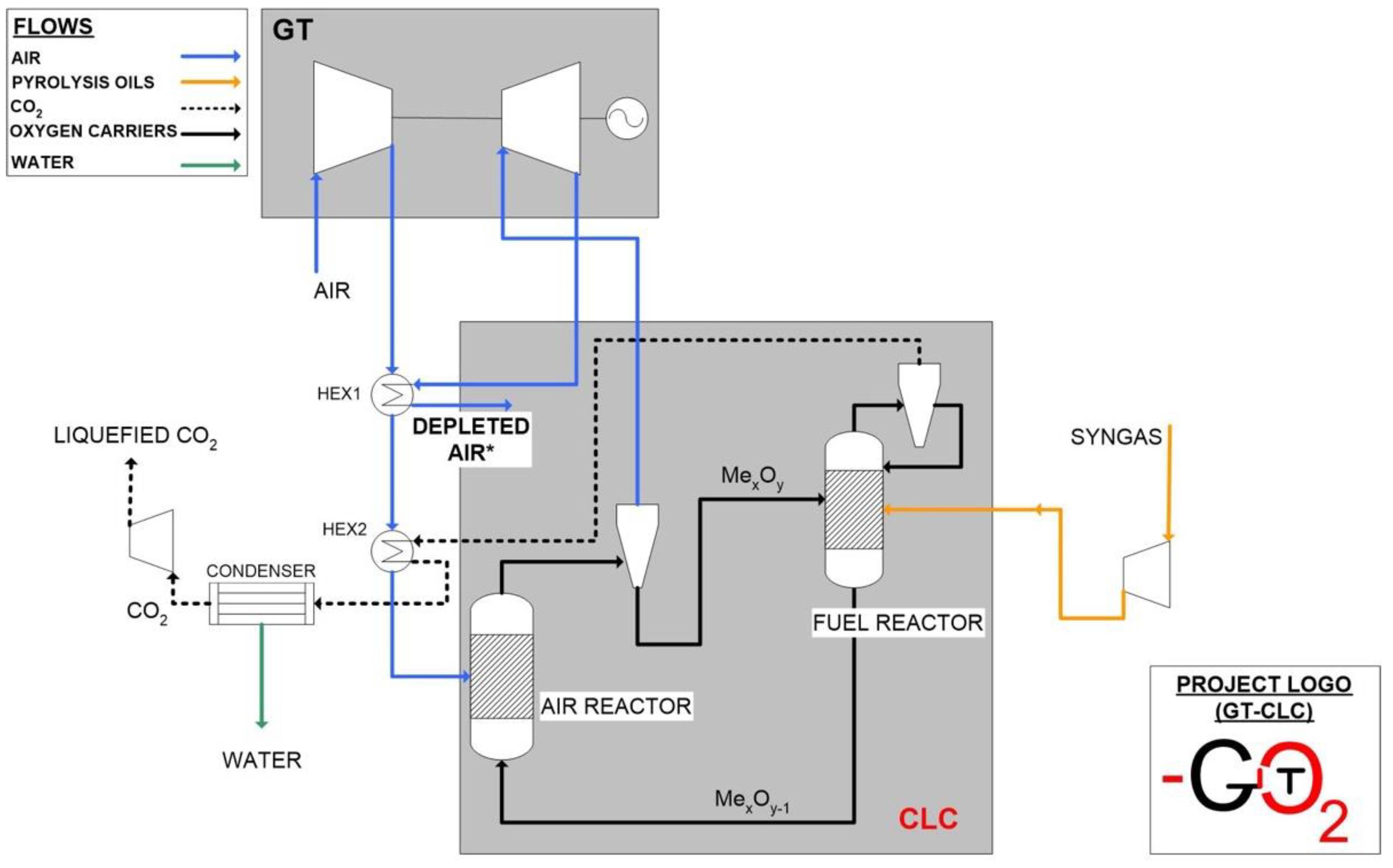
  • It can grant effective solid material circulation between the two reactors, ensuring oxygen to the fuel reactor and heat distribution among the two reactors.
  • Through an accurate management of the solids inventory across the height of both the reactors’ bodies, a satisfactory conversion of the gases fed to the air and to the fuel reactor can be achieved.
  • This is one of the more promising configurations that minimizes gas leakages between the two reactors through the presence of a loop seal, which enables to handle pressure differences among them.
Based on these considerations, we have introduced a revised procedure to design pressurized chemical looping combustors that have to be coupled to turbo expanders in power plants. In this case, the first difference we can note is that the air mass flow and the fuel mass flow are determined by the power that will be produced by the turbo expander connected to the air reactor. In this case, the revised design procedure for the whole plant is that shown in Figure 3. In this sense, this work can be considered an application of the previous theory developed in [14] with the aid of Aspen Plus.
We see from Figure 3 that for the design of the pressurized Chemical Looping Plant to be coupled to a gas turbine the following steps have to be undertaken:
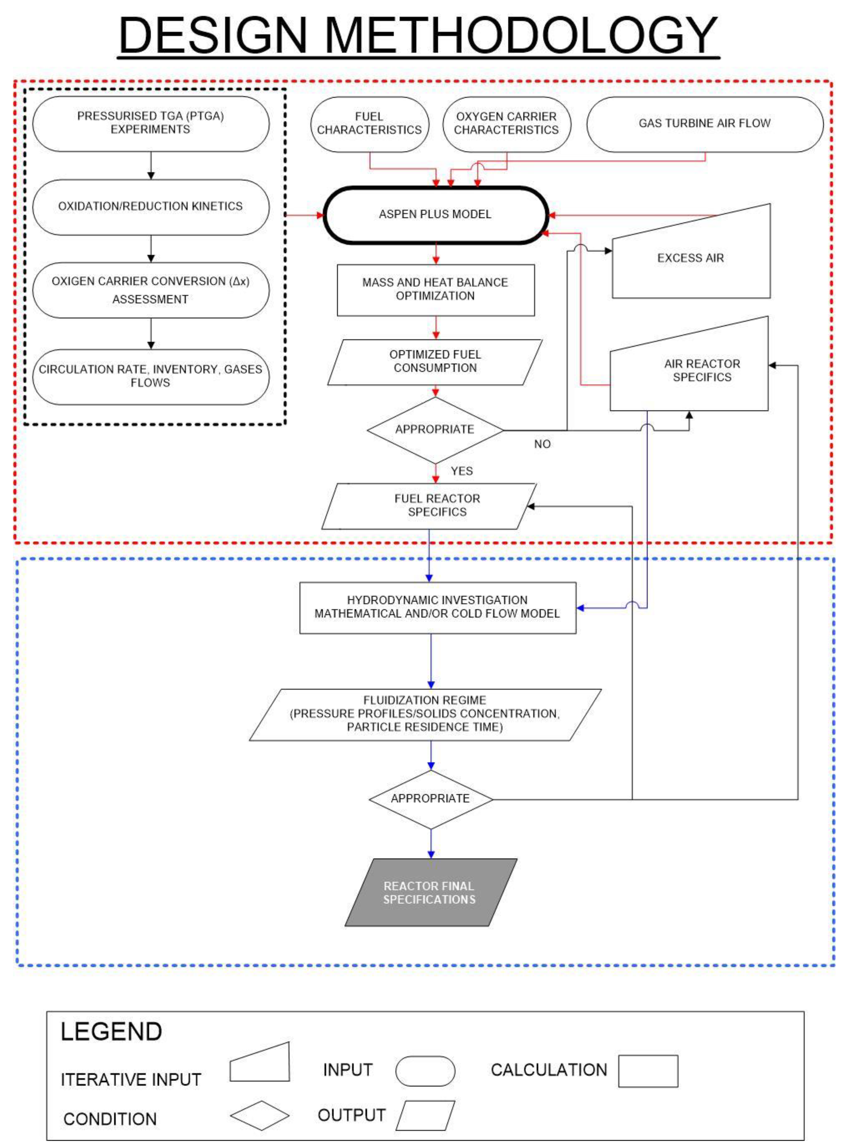
  • Firstly the power capacity of the gas turbine is considered and based on this the air mass flow is calculated, using Aspen Plus and assuming an excess air value which is iteratively optimized trying to reduce fuel consumption and maintaining a Turbine Inlet Temperature constant at 1200 °C;
  • Then from the stoichiometric air flow the fuel consumption is calculated (and it is used iteratively to optimize excess air consumption);
  • From the optimization process the air reactor and fuel reactor specification are determined, which are used to calculate the mass and energy balances of the air reactor and fuel reactor;
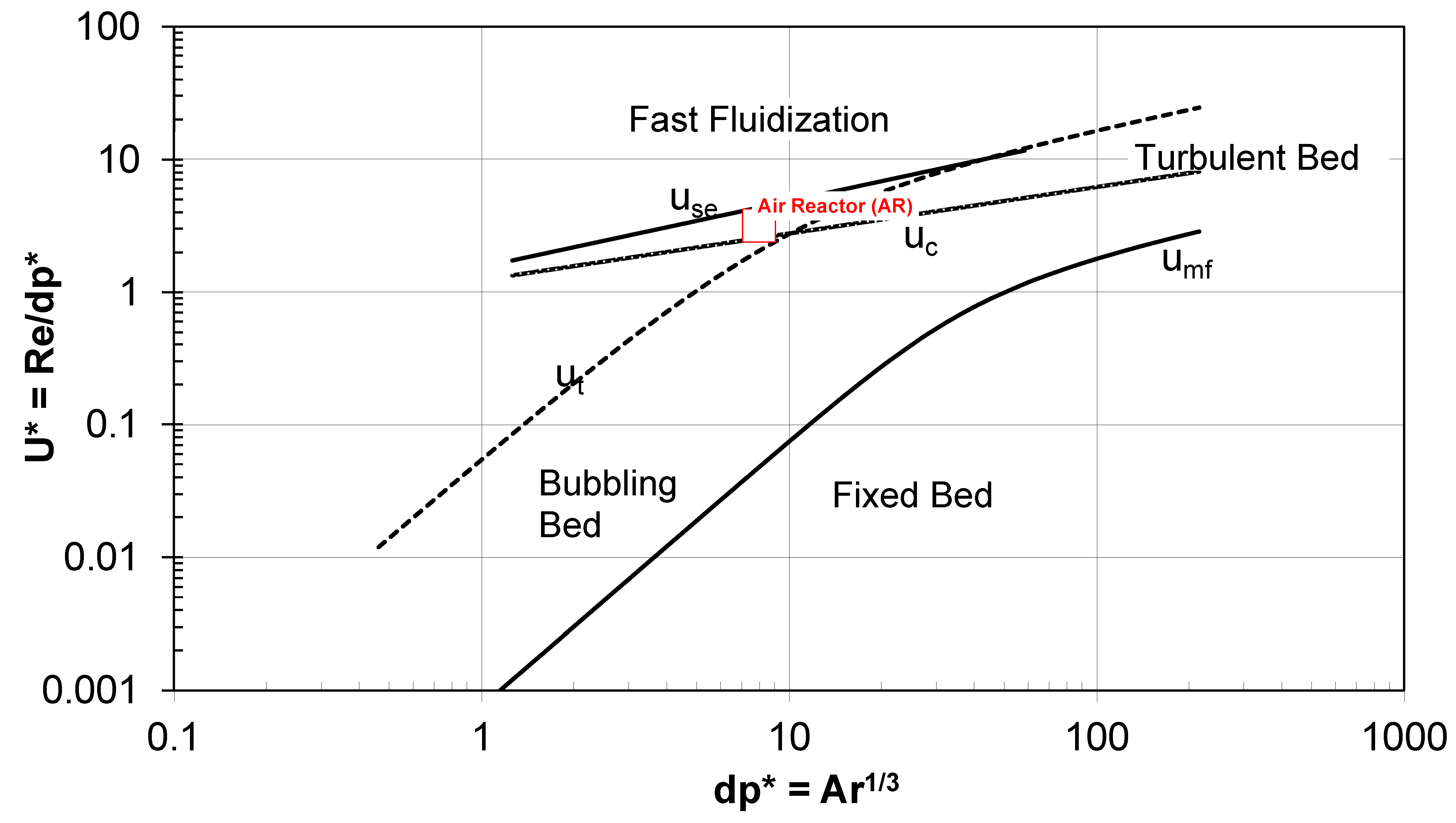
  • Then from the box delimited with red dotted lines which is about mass and energy balances optimization we pass to the box delimited with blue dotted lines which is instead on the hydrodynamics optimization we want in fact that both the air reactor and the fuel reactor are close to the fast fluidization regime which allows us to reduce the inventory and so also the operating costs of the plant. This is done by drawing the Grace diagram as it will be shown in the last paragraphs of this paper.
In this paper, we don’t design the whole plant, but focus only on the design of the air reactor which is one half of the total chemical looping combustor.
The aim of the study is to explore the impact of all the main factors affecting the design of Pressurized Air Reactors to be coupled with a turbo expander.

2. Materials and Methods

2.1. Fuel Mass Flow Calculation

A clear way to identify the inventory in the air rector is to refer to data on the kinetics of the oxidation reaction in pressurized conditions. Table 1 shows all the studies available on the subject.
As it can be seen from Table 1, the greater part of kinetic studies in pressurized conditions focuses on the reduction reaction which, as mentioned, is slower than the oxidation reaction. Nevertheless, to make an estimation of what should be the AR inventory, the oxidation kinetics is what to look at. In this respect, some data are provided by: [16,35,36]. In all the cited works, there is no hint at the final inventory needed in the air reactor, so we refer for this to the equation which has been reported in [17] and also the work published previously at the Instituto de Carboquimica–see [37,38].
In [37] for example, it is clearly shown how to calculate the solids inventory for both the air reactor and the fuel reactor. In [37] where the reactor design influence on reactivity is explained, we see that the first parameter to be identified is the circulation rate, so as to guarantee the required amount of oxygen and be sure to have full reduction in the fuel reactor. Then, the solids inventory can be calculated from the solids circulation rate.
The two units of measure of the solids inventory and of the circulation rate are reported in Table 2, according to [38].
From Table 2, it can be seen that the units of measure of both the inventory and the circulation rate are related to the power of the specific combustor. The difference between the inventory and the circulation rate is that while the inventory is a mass, the circulation rate is a mass flow. To calculate the total mass of oxygen carrier per reactor (fuel reactor and air reactor) and the circulation rate we need to know the power of the combustor. In the specific case in which a CLC combustor is connected with a turbo expander, the power of the combustor is linked to the power of the expander.
For example, let us assume that we have already developed in Aspen Plus V11 a power plant working with nickel-based oxygen carrier and using syngas obtained from biomass as a fuel. The power plant is based on the power of the turbo expander of 12 MWe. To produce this power, it is calculated by the Aspen plus model that about 135 t/h of air must be compressed at about 12 bars, and then expanded in the gas turbine. Now we have to consider that the excess air that expands in the gas turbine must be as high as possible–see for example what it is reported in [14] and also in [39], in which an excess air ratio up to 3.7 is proposed. At a constant Turbine Inlet Temperature (that we assume to be close to 1200 °C), if the excess air is high, the fuel consumption to obtain the same effect will be low and so the efficiency of the plant will be maximized.
If we chose an excess air of 3, we obtain that based on stoichiometric calculations, the stoichiometric air-to-fuel ratio for a syngas composed of 50 v% of CO and 50 v% of H2 is: 4.6 kg air/kg syngas. We have considered the air-to-fuel stoichiometric ratio for H2 is equal to about 34.7, as reported in [40], while the stoichiometric air-to-fuel ratio of CO combustion is about 2.5. This means that if we have a flow of 135 t/h air, the flow of methane will be equal to 9.7 t/h (equal to 90 moles/s of hydrogen and 90 moles/s of carbon monoxide). The mass of fuel has been calculated according to Equation (1).
m ˙ F = m ˙ AIR α / ATFR
where α is the excess air and ATFR is the Air to Fuel Ratio. Once the mass of the fuel is known, the circulation rate and the solids inventory will be calculated.

2.2. Solids Circulation Rate in the Air Reactor

The circulation rate is calculated mainly based on a mass balance applied to the fuel reactor and depends on the conversion variation of the oxygen carrier obtained in the fuel and air reactor. More on the solids conversion will be explained in Figure 4 at the end of this paragraph.
Now that we have the flow of syngas, we can calculate the circulation rate, according to Equation (2), which gives the total mass.
m ˙ ox = b r M NiO F f Δ X f / ( x NiO Δ X s )
where:
-
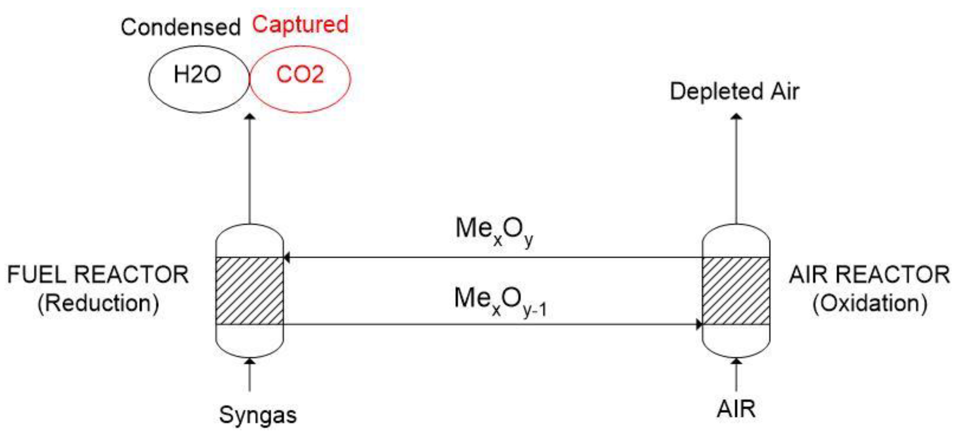
br is the stoichiometric factor in the reduction reactions (see number 3 and 4), expressed in mol of solid reacting per mol of fuel gas. In particular, if we refer to the fuel reactor, we will have to consider the following reactions:
NiO + CO → Ni + CO2
NiO + H2 → Ni + H2O
In reality, in the case of the use of oxygen carriers based on nickel oxides, we also must consider the water-gas-shift reaction, as will be explained in the further paragraphs.
-
In Equation (2), M is the molecular weight of the material, expressed in g per mole;
-
Ff is the molar flow of the fuel gas, expressed in moles/s;
-
ΔXf is the conversion rate of the fuel gas, which is assumed to be equal to 1;
-
xNiO is the mass fraction of NiO in the fully oxidized sample; this is indicated in many cases in the name of the catalyst, for example if we take into consideration the oxygen carrier Fe20γAl (which is used in [41]), this contains 20% in mass of active iron while the remaining is represented by the support (which in this case is gamma alumina). The content of metal oxide is usually measured with ICP-AES. In this specific case, we will consider Ni40Al-FG (where the two last letters mean freeze granulation) because it has been tested in pressurized conditions at the Instituto de Carboquimica, see [17];
-
ΔXs represents the conversion of the solids. In fact, not all the solids that are circulating in the reactor are fully converted; we can assume that 0.3 of the solids is converted, as reported for example in [37].
Equation (2) gives the total mass flow of the oxygen carrier; the quantity is not related to the fuel input. To relate the mass flow of the oxygen carrier to the fuel input we must consider the following [37]:
m ˙ OC = b r M NiO x NiO Δ H C 0 1 Δ X S , FR = m ˙ C Δ X S , FR
where ΔHC0 is the standard heat of combustion of the gas, which is indicated in kJ/mol. m ˙ C is the characteristic circulation rate, which is calculated as:
m ˙ C = b r M NiO x NiO Δ H C 0 = 2 dM O R 0 , OC Δ H C 0
The parameter d indicates the stochiometric factor in the fuel combustion reaction with oxygen, expressed in mol O2 per mol of fuel. As can be seen from Equation (7), another key parameter of the oxygen carrier is the R0, which is the oxygen transport capacity of the active metal oxide. The term “active metal oxide” indicates the part of the metal oxide that has not reacted with the support and so can actively behave as an oxygen carrier. The mass fraction of the metal oxide and the oxygen transport capacity are indicated in Table 2 for Ni40Al-FG and are also key parameters for the design of the fuel and air reactor. R0 can be calculated according to Equation (8);
R0 = (mox − mred)/mox
where mox and mred are the masses of the oxidized and reduced form of the oxygen carrier, respectively.
-
XS,o is the solids conversion in the oxidation reaction and can be calculated from Equation (9).
X S , o = 1 m ox m m ox R 0 x NiO
where m is the mass of the sample. In reality, in this case, we assume that:
-
in the air reactor, the oxygen carrier enters with Xo = 0.5 and exits with Xo = 0.8;
-
in the fuel reactor, the oxygen carrier enters with Xr = 0.2 and exits with Xr = 0.5
-
the solids conversion rate for reduction (ΔXr) and the solids conversion rate for oxidation (ΔXo) are both equal to 0.3.
The above cited values are reported in Figure 4. The main characteristics of the oxygen carrier used are shown in Table 3.
As said before, the oxygen carrier is derived from a freeze granulation preparation process, performed at Chalmers University, according to what is reported in [42]. Based on Equations (2) and (3), the final calculation of the circulation rate is equal to 111 kg/s, which is not excessive for a power plant producing 12 MWe and also considering other values reported in literature–see [36].

2.3. Solids Inventory Calculation for the Chemical Looping Combustion Plant

The solids inventory–as well as the solid circulation rate–is an important design parameter that is obtained from a mass balance performed at the air reactor and at the fuel reactor. Thus, in this case we will have an optimal inventory for the air reactor and an optimal inventory of the fuel reactor. As mentioned previously, these inventories will influence the bed particles distribution, the height, and the pressure drop inside the two reactors.
For what has been said above, the mass of oxygen carrier that is totally oxidized can be calculated based on the molar flow of the fuel gas [37], see the following equations:
m ox , FR = ρ NiO b r F f x NiO ( r ¯ NiO ) r
m ox , AR = M NiO M Ni ρ NiO b r F f x NiO ( r ¯ Ni ) o
where:
-
mOX,FR and mOX,AR are the inventory in the fuel reactor and in the air reactor, respectively.
-
ρNiO is the density of the oxygen carrier, as reported in Table 2;
-
( r ¯ NiO ) r and ( r ¯ Ni ) o are the average reaction rates of the oxygen carrier per unit volume of the reacting solid, which can be calculated as follows:
( r ¯ NiO ) r = ρ m , NiO dX ¯ s , r dt = ρ m , NiO 0 tr dX S , r dt E FR ( t ) dt
( r ¯ Ni ) o = ρ m , Ni dX ¯ s , o dt = ρ m , Ni 0 to dX S , o dt E AR ( t ) dt
where XS,r and XS,o are the conversion of the solids in the fuel reactor and in the air reactor, respectively. They can be calculated using the following equations:
XS,r = t/τr
XS,o = t/τo
The terms with the hat mean essentially that we are considering averaged values. We must also consider that:
dX S , r dt = 1 τ ¯ r
dX S , o dt = 1 τ ¯ o
In this case, 1 τ ¯ r and 1 τ ¯ o are given by the following equations:
t τ r = 1 ( 1 X r ) 1 / 3                   τ r = ρ m r g b r k r ( C n C eq n )
t τ o = 1 ( 1 X o ) 1 / 3                   τ o = ρ m r g b o k o ( C O 2 n )
The equations shown are derived using a Shrinking Core Model (SCM) with sphere-like geometry, which is the one correspondent to the nickel catalyst that we are considering in this study. The term Cneq considers the thermodynamic equilibrium in the reactant gas when nickel is used as an oxygen carrier.
EFR(t) and EAR(t) represent the residence time distributions of the carrier particles in the two beds (assuming that they behave as a completely mixed flow reactor, CMFR), and they can be calculated through the following equations:
E FR ( t ) = e t / t ¯ FR / t ¯ FR
E AR ( t ) = e t / t ¯ AR / t ¯ AR
where:
-
t ¯ FR and t ¯ AR are the mean residence times in the two reactors (respectively, fuel and air reactor) and depend on the circulation rate and the reactor volume, assuming that the solids circulate with plug flow behavior.
-
To first define tr and to, we must make the assumption that the oxygen carrier that enters the fuel and air reactor is already partially converted (as it was also shown in Figure 4). The values of conversion at the inlet of the reactors are indicated, respectively, as: X ¯ r ,   in   FR and X ¯ o ,   in   AR and are higher than 0. Once this has been cleared, the quantities of tr and to are defined as the time needed for a particle to react from conversion equal to zero to the maximum variation of oxygen conversion (i.e., 1 − X ¯ r ,   in   FR and 1 − X ¯ o ,   in   AR ). The two equations indicating tr and to are presented below.
t r = ρ m , NiO L NiO b r k r C ¯ f n ( 1 X ¯ r , inFR )
t r = ρ m , NiO L NiO b o k o C ¯ O 2 n ( 1 X ¯ o , inAR )
L is the layer thickness of the reacting solid; this is calculated considering the Active Surface Area (ASA) obtained from H2 chemisorption and the weight fraction of active metal oxide in the oxygen carrier particle.
The two terms C ¯ f n and C ¯ O 2 n represent the average concentration of reacting gas in the fuel reactor and the average concentration of oxygen in the air reactor. These can be both calculated with a general equation, which integrates the gas concentration along the length of the reactor.
C ¯ g n = Δ X g C g , 0 n X g , in X g , out [ 1 + ε g X g 1 X g ] n dX g
where the parameter εg represents the volume variation, due to the reactions happening in the fuel and in the air reactor, the volume variation is 0 for H2 and CO because 1 mole of H2 gives 1 mole of H2O and 1 mole of CO gives 1 mole of CO2. For the oxidation reaction, we have a value of −0.21 because the oxygen in the air (expressed in volume percentage) is “loaded” in the oxygen carrier and practically disappears from the gases contained in the reactor.
From the calculations shown above (especially in Equations (10) and (11)), the final equation to evaluate the inventory of the oxygen carrier for the fuel reactor can be derived:
m OC = y g Δ X g 2 dM O R 0 τ ¯ r Φ FR
Equation (25) is used for the determination of the solids inventory of the fuel reactor. For the determination of the inventory of the oxygen carrier in the air reactor we simply substitute the τ ¯ r and the Φ FR with τ ¯ o and Φ AR .
Dealing with the other parameters contained in Equation (25):
-
yg can be considered equal to 1.
-
Δ X g is equal to 0.999.
-
R0 (as already said) is a parameter which is typical of the oxygen carrier.
-
d is typical of the reaction.
-
Mo is the molecular mass of oxygen (so it is 16).
In fact, d is the stochiometric factor in the fuel combustion reaction with oxygen (expressed in mol O2 per mol of fuel). As already said, the expression: 2 dM O R 0 represents the characteristic circulation rate (also identified with the symbol: m ˙ c ) and it is analogous to that reported in Equation (7).
We must consider that the enthalpy of the reaction can be also included at the denominator of Equation (25) if we want to express the characteristic circulation rate, based on the MW of primary energy of the reactor.
The parameter ΦFR is the characteristic reactivity, which depends on the solid conversion at the inlet, Xr,in and the conversion variation ΔXr, see [38]. The characteristic reactivities for the two considered reactors are calculated based on the following equations.
Φ FR = [ τ r dX s ¯ dt ] FR
Φ AR = [ τ o dX s ¯ dt ] AR
The characteristic reactivity can be also expressed as a function of the solids conversion at the inlet of the reactor and the conversion variation inside the reactor; in this way, we obtain two equations: the first for spherical grain geometry and the second for plate-like geometry, see [38].
Φ j = 3 [ 1 X ¯ o , in   j 2 / 3 exp ( ( 1 X ¯ o , in   j 1 / 3 ) Δ X s Φ j ) ] 6 Δ X s Φ j [ 1 X ¯ o , in   j 1 / 3 exp ( ( 1 X ¯ o , in   j 1 / 3 ) Δ X s Φ j ) ] + 6 Δ X s 2 Φ j 2 [ 1 exp ( ( 1 X ¯ o , in   j 1 / 3 ) Δ X s Φ j ) ]
Φ j = 1 exp ( ( 1 X ¯ o , in   j 1 / 3 ) Δ X s Φ j )
As the oxygen carrier used, in this case, spheric-like geometry, equation number 29 was considered. The final inventory of the whole plant is given by the sum of the inventory of the fuel reactor and that of the air reactor. If we have a fuel, like syngas, composed of two burning species (like H2 and CO), the inventory of the air reactor will be the sum of the inventories that are necessary to oxidise hydrogen and carbon monoxide.
Applying the above determined equations, we calculated a final inventory for the air reactor of about 2720 kg. It must also be considered that, as reported in [43], the real inventory that is needed can be 2–10 times higher than the theoretical one. Thus, we foresee that the real inventory for the air reactor would be about 10,880 kg (about four times the theoretical one).

2.4. Particle Size Distribution inside the Air Reactor

To model the Particle Size Distribution inside the air reactor, a PSD mesh is used and it is shown in Table 4, as calculated with Apen Plus V11. To realize the mesh, a distribution function is built. This is based on the GGS (Gates–Gaudin–Schuhmann) approach, see [44]. The dispersion parameter is set to 1.5 and the maximum diameter is set to 10 mm.

2.5. Transport Disengaging Height (TDH) and Elutriation Models: Influence on Circulation Rate and on Air Velocity Inside the Reactor

Once the circulation rate has been calculated, we have to see which is the optimal velocity to ensure that circulation happens with the desired rate. If we have fixed the mass flow of air, the only way we have to set the velocity to the desired values is to change the section of the reactor. We also know that the average value of the cross section area for both the air and the fuel reactor has been identified to be close to the number of 0.2 m2/MWth [43]. If we consider the layout proposed in Figure 1, we can see that by adjusting the diameter of the air reactor to about 1.8 m we obtain that the cyclone can separate about 110 kg/s of solids, which can then be recirculated; thus, we finally found the geometrical parameter that grants a predetermined circulation rate.
The circulation rate is clearly caused by the elutriation of the particles in the air reactor and is also caused by the fact that the transport disengaging height is higher than the height of the reactor.
The equation used to model the elutriation process is the following:
ki,∞ = A × ρG × uB × expo (C – ut,i/u)
where:
-
ki,∞ is the elutriation coefficient, expressed in kg/(m2s);
-
ρG, is the gas density expressed in kg/m3;
-
ut,I is the particle terminal velocity, expressed in m/s;
-
u is the fluidizing velocity, expressed in m/s.
While the elutriation model refers to the formulation of Tasirin Geldart [45], for the Transport Disengaging Height, the model of [46] is considered. In reality, there are several empirical models available in the literature to estimate the Transport Disengaging Height (TDH)–see for example: [47]. To understand how it influences the circulation rate, it is better to have clear the theory behind it.
The phenomenon is practically due to bubble bursting in the surface of a bubbling fluidized bed, which then projects particles in the freeboard. Depending on the terminal velocity of the particles (Ut) and the gas velocity (U), the particles can be entrained in the flow of the gas at different heights. On the other hand, the solids concentration (kg solids/m3 gas) will decline with the height of the reactor.
The upper part of the bed where the solids concentration definitely decreases is called the transport disengaging height. The dilute phase transport zone is an area where only fine particles with Ut < U are present. Their concentration further decreases to a constant value. The most important aspect of the Transport Disengaging Height is that it influences the entrainment rate [48], the circulation rate [49], and also the reaction rate in the freeboard [50]. The transport disengaging height can be easily correlated with the pressure gradient inside the freeboard of the reactor [47].
This parameter affects the design of the air reactor in an important way. First, together with the diameter of the reactor, we must choose the height. Let us assume that the diameter of the reactor was chosen to have a superficial velocity that is around 2–4 m/s and grants that the reactor is in a fast fluidization regime. This will happen with a diameter of 1.8 m. At this point, Aspen Plus V11 provides two Transport Disengaging Heights:
-
the first is calculated from correlation;
-
the second is calculated based on the volume fraction profile.
While the one based on the solid volume fraction profile is about 1.8 m, the other is much higher because in the air reactor, elutriation is needed to grant recirculation of the oxygen carrier; thus, in this sense, it is not a negative phenomenon. The ratio between the diameter and height in this case resembles that reported in [7].

3. Results

3.1. Final Design of the Air Reactor

The air reactor, which consist of a riser, has been modeled with Aspen Plus, V11.
This version of the software already has a model to implement a fluidized bed, which is available in the section “solids” with the reactor “Fluidbed”. The input parameters used to model the fluidized bed are reported in Table 5, while the final results are proposed in Table 6. The bed mass is derived directly from the inventory of the air reactor. As already said, the diameter and the height of the air reactor are, respectively: diameter: 1.8 m, height: 9.5 m.
The diameter is selected to grant a velocity that is typical of the fast fluidization regime; the height is granted to provide a concentration of solids that is similar to that encountered in the circulation riser.
Dealing with the difference between the:
-
Transport Disengaging Height calculated by correlation;
-
Transport Disengaging Height based on solids volume fraction profile;
This is clearly reported in [54], from which we understand that the TDH calculated by correlation is basically very dependent of what are reactor characteristics and its behavior while TDH calculated on solids volume fraction profile is a calculation done internally by Aspen Plus based on the same definition of the TDH which is the height at which solids entrainment does not change significantly or the height at which the solids loading is declining.

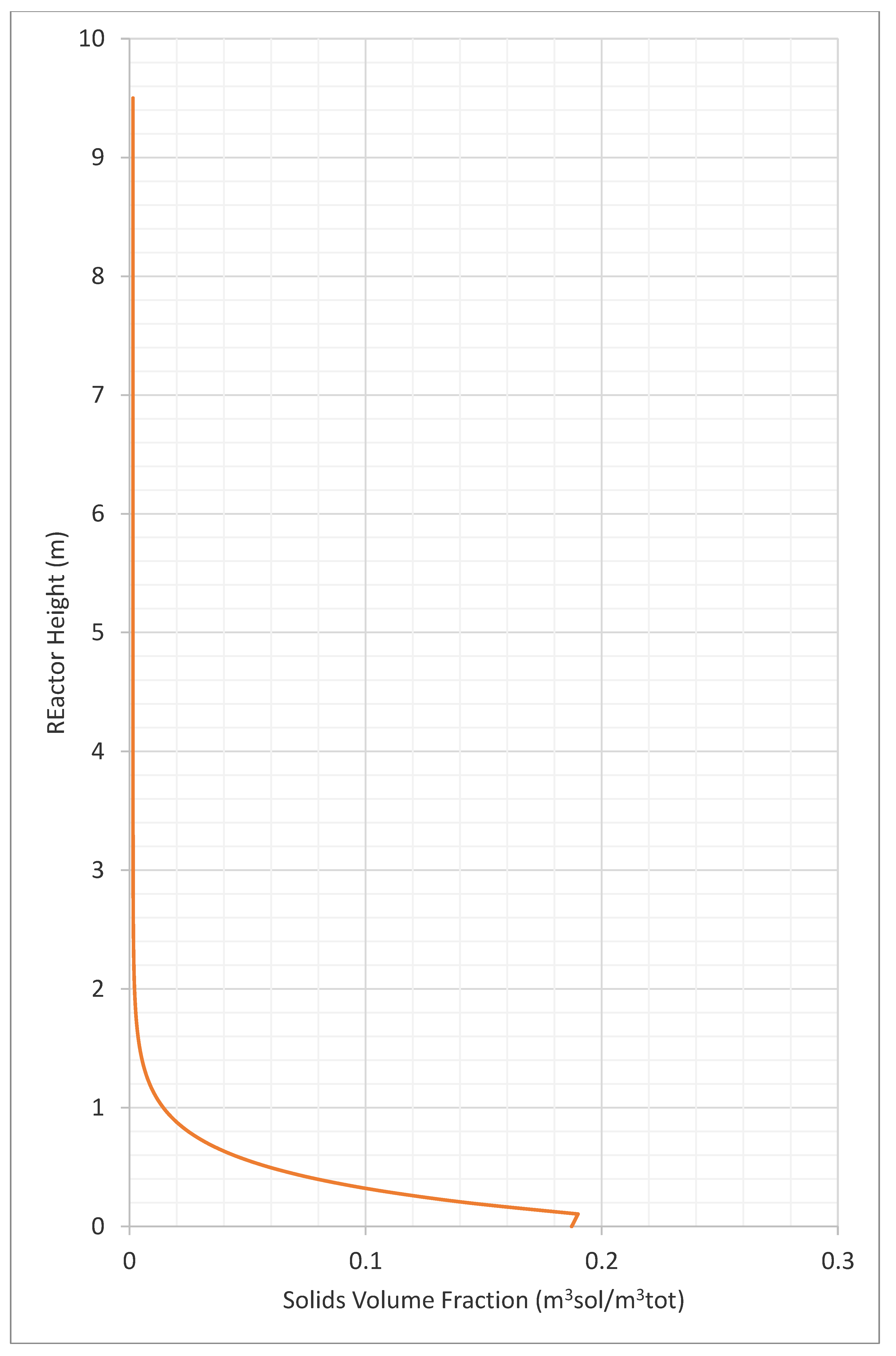
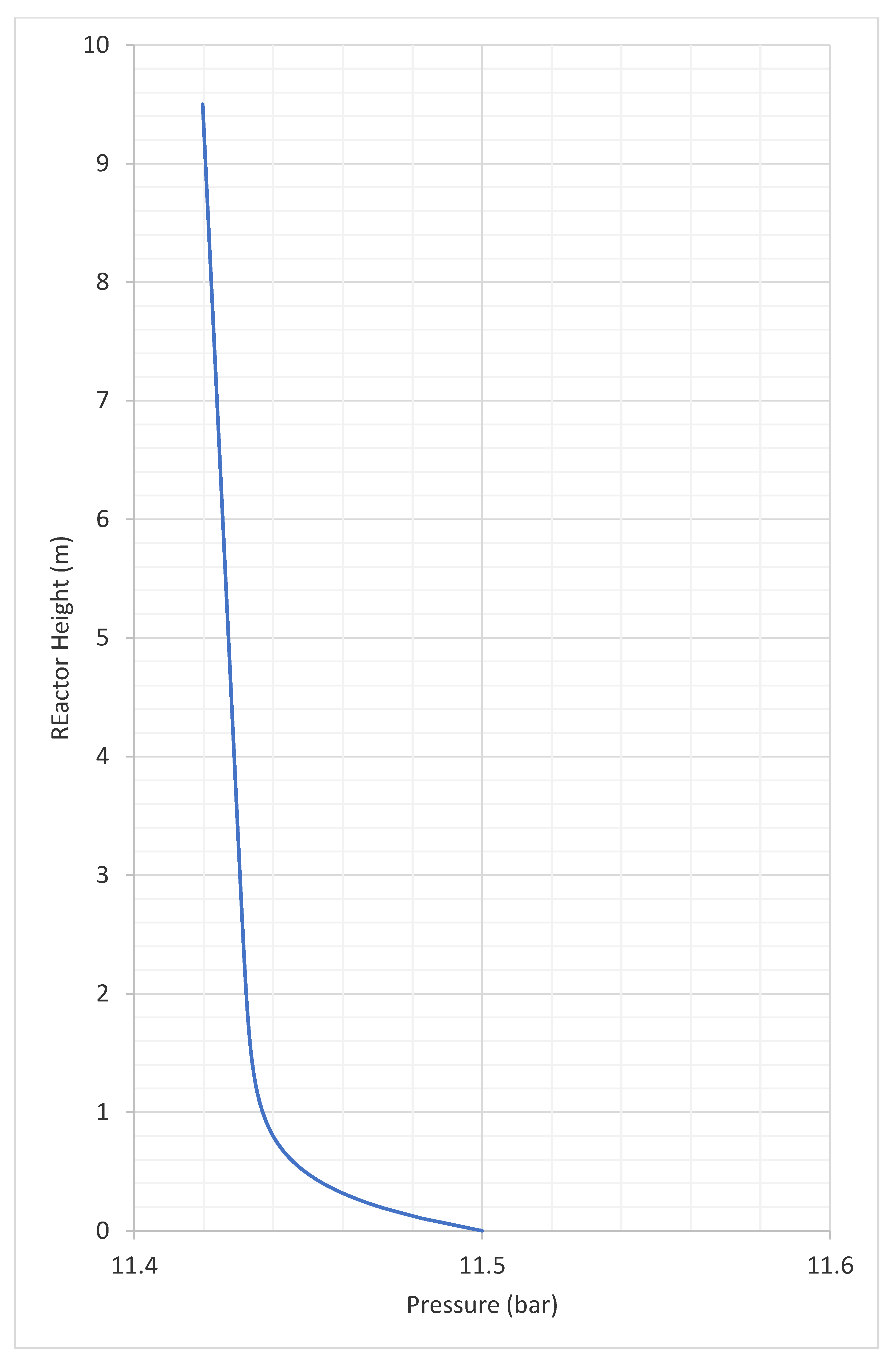
3.2. Profiles of Velocity, Solids Volume Fraction

The final profiles of:
-
superficial velocity (m/s)
-
interstitial velocity (m/s)
-
solids volume fraction (-)
-
pressure (bar).
The velocities profiles inside the air reactor are proposed in Figure 5.
As it can be seen from Figure 5, the bed of the air reactor is full of particles up to the height of 1–2 m; in this way, the interstitial velocity is higher than the superficial velocity and decreases rapidly when the freeboard begins. These numbers are correspondent to the order of magnitude of the velocities, which are reported in Kronberger et al., 2005 [7]. The solids volume fraction in the air reactor is presented in Figure 6.
As said before in Figure 6, it can be seen that the lower part of the air reactor hosts a bed of particles, which then decrease their concentration. The pressure trend inside the air reactor is shown in Figure 7.
In the air reactor, there is the need to entrain the greater part of the solids in the flow of air, to bring them to the cyclone, and then recirculate them. Thus, after 2 m of height, the particles result to be very rarified.
Finally, we propose in Figure 8 the description of the fluidization regime based on the Grace diagram and theory [56]. The two parameters described in the graph are given by the following equations:
u* = Re/dp*
dp* = Ar1/3
Ar = dp3ρgp − ρg)g/υp
Re = ρgudpg
The Reynolds number is that referred to the particles given by the following equation (taken from [57]): where:
-
ρg is the density of the gas;
-
u is the velocity of the gas (m/s);
-
dp is the diameter of the particles (m);
-
μg is he gas viscosity (cp).
Figure 8. Pressure trend in the circulating riser. Modified from [58,59].
Energies 16 02102 g008
As it can be seen from the scheme, we have a flow regime that is comprised between the turbulent and the fast fluidization regime. We have been iterating with this while finalizing the design, according to the proposed methodology, to doublecheck being in the appropriate fluidization regime.

4. Conclusions

The paper has presented a model for the dimensioning of an air reactor to be coupled to a gas turbine of the power of about 12 MW, based on the hot air mass flow requirements to produce such a power. The fluidized bed is designed by choosing geometry parameters and making a detailed analysis of the influence of geometry on velocity profiles, solids concentration, and pressure drop characteristics. It can be seen from the analysis presented in this paper that the diameter of the fluidized bed is mainly influenced by the mass flow of the air in the reactor, while the height of the reactor is mainly influenced by the elutriation and transport disengaging height calculations. A further step will be to couple the air reactor model with a model of the fuel reactor and to introduce more effective models of chemical reactions. A complete enthalpy balance of reduction and oxidation reactions can be realized through CFD software.

Author Contributions

Conceptualization, A.A. and F.F.; methodology, M.Z. and A.B.; software, L.W. and H.Y.; validation, A.C. and M.d.L.O.L.; P.B. paper writing and conceptualization. All authors have read and agreed to the published version of the manuscript.

Funding

This work has been partially funded by the GTCLC-NEG project that has received funding from the European Union’s Horizon 2020 research and innovation programme under the Marie Sklodowska-Curie grant agreement No. 101018756.

Data Availability Statement

Data are publicly available in the project repository in Zenodo: https://zenodo.org/deposit?page=1&size=20 (accessed on 15 January 2023).

Acknowledgments

This work has been funded by the GTCLC-NEG project that has received funding from the European Union’s Horizon 2020 research and innovation programme under the Marie Sklodowska-Curie grant agreement No. 101018756. Special Acknowledgments are given to William A. Rogers of the National Energy Technology Laboratory (US) for helping in the concluding remarks on the arrangements needed to carefully model the effect of pressure on the PCLC plant.

Conflicts of Interest

The authors declare no conflict of interest.

References

  1. Fridahl, M.; Lehtveer, M. Bioenergy with carbon capture and storage (BECCS): Global potential, investment preferences, and deployment barriers. Energy Res. Soc. Sci. 2018, 42, 155–165. [Google Scholar] [CrossRef]
  2. Rydén, M.; Lyngfelt, A.; Langørgen, Ø.; Larring, Y.; Brink, A.; Teir, S.; Havåg, H.; Karmhagen, P. Negative CO2 emissions with chemical-looping combustion of biomass–a Nordic energy research flagship project. Energy Procedia 2017, 114, 6074–6082. [Google Scholar] [CrossRef]
  3. Zhao, X.; Zhou, H.; Sikarwar, V.S.; Zhao, M.; Park, A.-H.A.; Fennell, P.S.; Shen, L.; Fan, L.-S. Biomass-based chemical looping technologies: The good, the bad and the future. Energy Environ. Sci. 2017, 10, 1885–1910. [Google Scholar] [CrossRef] [Green Version]
  4. Lyngfelt, A.; Brink, A.; Langørgen, Ø.; Mattisson, T.; Rydén, M.; Linderholm, C. 11,000 h of chemical-looping combustion operation—Where are we and where do we want to go? Int. J. Greenh. Gas Control 2019, 88, 38. [Google Scholar]
  5. Bhui, B.; Vairakannu, P. Prospects and issues of integration of co-combustion of solid fuels (coal and biomass) in chemical looping technology. J. Environ. Manag. 2019, 231, 1241–1256. [Google Scholar] [CrossRef] [PubMed]
  6. Yu, L.; Zhou, W.; Luo, Z.; Wang, H.; Liu, W.; Yin, K. Developing Oxygen Carriers for Chemical Looping Biomass Processing: Challenges and Opportunities. Adv. Sustain. Syst. 2020, 4, 2000099. [Google Scholar] [CrossRef]
  7. Osman, M.; Khan, M.N.; Zaabout, A.; Cloete, S.; Amini, S. Review of pressurized chemical looping processes for power generation and chemical production with integrated CO2 capture. Fuel Processing Technol. 2021, 214, 10668. [Google Scholar]
  8. Kronberger, B.; Lyngfelt, A.; Löffler, G.; Hofbauer, H. Design and Fluid Dynamic Analysis of a Bench-Scale Combustion System with CO2 Separation−Chemical-Looping Combustion. Ind. Eng. Chem. Res. 2005, 44, 546–556. [Google Scholar] [CrossRef]
  9. De Leeuwe, C.; Zaheer Abbas, S.; Alexandros Argyris, P.; Zaidi, A.; Amiero, A.; Poultson, S.; Wails, D.; Spallina, V. Thermochemical syngas generation via solid looping process: An experimental demonstration using Fe-based material. Chem. Eng. J. 2022, 453, 139791. [Google Scholar] [CrossRef]
  10. Abbas, S.Z.; Fernández, J.R.; Amieiro, A.; Rastogi, M.; Brandt, J.; Spallina, V. Lab-scale experimental demonstration of CaCu chemical looping for hydrogen production and in-situ CO2 capture from a steel-mill. Fuel Processing Technol. 2022, 237, 107475. [Google Scholar] [CrossRef]
  11. Alexandros Argyris, P.; de Leeuwe, C.; Abbas, S.Z.; Amieiro, A.; Poultson, S.; Wails, D.; Spallina, V. Chemical looping reforming for syngas generation at real process conditions in packed bed reactors: An experimental demonstration. Chem. Eng. J. 2022, 435, 134883. [Google Scholar] [CrossRef]
  12. Argyris, P.A.; Wright, A.; Taheri Qazvini, O.; Spallina, V. Dynamic behaviour of integrated chemical looping process with pressure swing adsorption in small scale on-site H2 and pure CO2 production. Chem. Eng. J. 2022, 428, 132606. [Google Scholar] [CrossRef]
  13. Ugwu, A.; Arnaiz del Pozo, C.; Zaabout, A.; Nazir, S.M.; Kalendar, N.U.; Cloete, S.; Szima, S.; Fogarasi, S.; Donat, F.; van Diest, G.; et al. Gas switching technology: Economic attractiveness for chemical looping applications and scale up experience to 50 kWth. Int. J. Greenh. Gas Control 2022, 114, 103593. [Google Scholar] [CrossRef]
  14. Bischi, A.; Langørgen, Ø.; Saanum, I.; Bakken, J.; Seljeskog, M.; Bysveen, M.; Morin, J.-X.; Bolland, O. Design study of a 150 kWth double loop circulating fluidized bed reactor system for chemical looping combustion with focus on industrial applicability and pressurization. Int. J. Greenh. Gas Control 2011, 5, 467–474. [Google Scholar]
  15. Bartocci, P.; Abad, A.; Cabello Flores, A.; de las Obras Loscertales Navarro, M.; Pelucchi, M.; Andrea, T.; Wang, L.; Haiping, Y.; Haibo, Z.; Qing, Y. Integration of multiphase CFD models with detailed kinetics to understand the behavior of oxygen carriers under pressurized conditions. In Proceedings of the 13th International Conference on Applied Energy (ICAE2021), Online, 29 November–2 December 2021; pp. 1–6. [Google Scholar]
  16. García-Labiano, F.; Adánez, J.; de Diego, L.F.; Gayán, P.; Abad, A. Effect of Pressure on the Behavior of Copper-, Iron-, and Nickel-Based Oxygen Carriers for Chemical-Looping Combustion. Energy Fuels 2006, 20, 26–33. [Google Scholar] [CrossRef] [Green Version]
  17. Abad, A.; García-Labiano, F.; de Diego, L.F.; Gayán, P.; Adánez, J. Reduction Kinetics of Cu-, Ni-, and Fe-Based Oxygen Carriers Using Syngas (CO + H2) for Chemical-Looping Combustion. Energy Fuels 2007, 21, 1843–1853. [Google Scholar] [CrossRef] [Green Version]
  18. Siriwardane, R.; Poston, J.; Chaudhari, K.; Zinn, A.; Simonyi, T.; Robinson, C. Chemical-Looping Combustion of Simulated Synthesis Gas Using Nickel Oxide Oxygen Carrier Supported on Bentonite. Energy Fuels 2007, 21, 1582–1591. [Google Scholar] [CrossRef]
  19. Gu, H.; Shen, L.; Xiao, J.; Zhang, S.; Song, T.; Chen, D. Evaluation of the Effect of Sulfur on Iron-Ore Oxygen Carrier in Chemical-Looping Combustion. Ind. Eng. Chem. Res. 2013, 52, 1795–1805. [Google Scholar] [CrossRef]
  20. Zhang, S.; Xiao, R.; Zheng, W. Comparative study between fluidized-bed and fixed-bed operation modes in pressurized chemical looping combustion of coal. Appl. Energy 2014, 130, 181–189. [Google Scholar] [CrossRef]
  21. Xiao, R.; Song, Q.; Zhang, S.; Zheng, W.; Yang, Y. Pressurized Chemical-Looping Combustion of Chinese Bituminous Coal: Cyclic Performance and Characterization of Iron Ore-Based Oxygen Carrier. Energy Fuels 2010, 24, 1449–1463. [Google Scholar] [CrossRef]
  22. Xiao, R.; Song, Q.; Song, M.; Lu, Z.; Zhang, S.; Shen, L. Pressurized chemical-looping combustion of coal with an iron ore-based oxygen carrier. Combust. Flame 2010, 157, 1140–1153. [Google Scholar] [CrossRef]
  23. Luo, S.; Zeng, L.; Xu, D.; Kathe, M.; Chung, E.; Deshpande, N.; Qin, L.; Majumder, A.; Hsieh, T.-L.; Tong, A. Shale gas-to-syngas chemical looping process for stable shale gas conversion to high purity syngas with a H 2: CO ratio of 2: 1. Energy Environ. Sci. 2014, 7, 4104–4117. [Google Scholar]
  24. Deshpande, N.; Majumder, A.; Qin, L.; Fan, L.-S. High-pressure redox behavior of iron-oxide-based oxygen carriers for syngas generation from methane. Energy Fuels 2015, 29, 1469–1478. [Google Scholar]
  25. Hamers, H.; Gallucci, F.; Williams, G.; Cobden, P.; van Sint Annaland, M. Reactivity of oxygen carriers for chemical-looping combustion in packed bed reactors under pressurized conditions. Energy Fuels 2015, 29, 2656–2663. [Google Scholar]
  26. San Pio, M.; Gallucci, F.; Roghair, I.; van Sint Annaland, M. Gas-solids kinetics of CuO/Al2O3 as an oxygen carrier for high-pressure chemical looping processes: The influence of the total pressure. Int. J. Hydrog. Energy 2017, 42, 12111–12121. [Google Scholar] [CrossRef] [Green Version]
  27. Lu, X.; Rahman, R.A.; Lu, D.Y.; Ridha, F.N.; Duchesne, M.A.; Tan, Y.; Hughes, R.W. Pressurized chemical looping combustion with CO: Reduction reactivity and oxygen-transport capacity of ilmenite ore. Appl. Energy 2016, 184, 132–139. [Google Scholar]
  28. Tan, Y.; Ridha, F.N.; Lu, D.Y.; Hughes, R.W. Reduction kinetics of ilmenite ore for pressurized chemical looping combustion of simulated natural gas. Energy Fuels 2017, 31, 14201–14210. [Google Scholar] [CrossRef]
  29. Tan, Y.; Ridha, F.N.; Duchesne, M.A.; Lu, D.Y.; Hughes, R.W. Reduction kinetics of ilmenite ore as an oxygen carrier for pressurized chemical looping combustion of methane. Energy Fuels 2017, 31, 7598–7605. [Google Scholar] [CrossRef]
  30. Chen, L.; Kong, L.; Bao, J.; Combs, M.; Nikolic, H.S.; Fan, Z.; Liu, K. Experimental evaluations of solid-fueled pressurized chemical looping combustion–The effects of pressure, solid fuel and iron-based oxygen carriers. Appl. Energy 2017, 195, 1012–1022. [Google Scholar] [CrossRef] [Green Version]
  31. Tian, Q.; Su, Q. Performance of a Cu-based oxygen carrier with pressurized CH4 in a fixed bed CLC process. In Proceedings of the 2017 2nd International Conference on Civil, Transportation and Environmental Engineering (ICCTE 2017), Shenzhen, China, 10–11 May 2017. [Google Scholar]
  32. Lee, D.; Nam, H.; Kim, H.; Hwang, B.; Baek, J.-I.; Ryu, H.-J. Experimental screening of oxygen carrier for a pressurized chemical looping combustion. Fuel Processing Technol. 2021, 218, 106860. [Google Scholar] [CrossRef]
  33. Nordness, O.; Han, L.; Zhou, Z.; Bollas, G.M. High-pressure chemical-looping of methane and synthesis gas with Ni and Cu oxygen carriers. Energy Fuels 2016, 30, 504–514. [Google Scholar] [CrossRef]
  34. Guo, X.; Li, Y.; Zhu, Q.; Hu, X.; Ma, J.; Guo, Q. Reactivity of iron-based oxygen carriers with coal ash in pressurized chemical looping gasification. Fuel Processing Technol. 2021, 219, 106890. [Google Scholar]
  35. Díez-Martín, L.; Grasa, G.; Murillo, R.; Martini, M.; Gallucci, F.; van Sint Annaland, M. Determination of the oxidation kinetics of high loaded CuO-based materials under suitable conditions for the Ca/Cu H2 production process. Fuel 2018, 219, 76–87. [Google Scholar]
  36. Rana, S.; Sun, Z.; Mehrani, P.; Hughes, R.; Macchi, A. Ilmenite oxidation kinetics for pressurized chemical looping combustion of natural gas. Appl. Energy 2019, 238, 747–759. [Google Scholar] [CrossRef]
  37. García-Labiano, F.; de DIEGO, L.F.; Adánez, J.; Abad, A.; Gayán, P. Reduction and oxidation kinetics of a copper-based oxygen carrier prepared by impregnation for chemical-looping combustion. Ind. Eng. Chem. Res. 2004, 43, 8168–8177. [Google Scholar]
  38. Abad, A.; Adánez, J.; García-Labiano, F.; Luis, F.; Gayán, P.; Celaya, J. Mapping of the range of operational conditions for Cu-, Fe-, and Ni-based oxygen carriers in chemical-looping combustion. Chem. Eng. Sci. 2007, 62, 533–549. [Google Scholar] [CrossRef] [Green Version]
  39. Oh, D.-H.; Lee, C.-H.; Lee, J.-C. Performance and Cost Analysis of Natural Gas Combined Cycle Plants with Chemical Looping Combustion. ACS Omega 2021, 6, 21043–21058. [Google Scholar] [CrossRef]
  40. Ji, C.; Xin, G.; Wang, S.; Cong, X.; Meng, H.; Chang, K.; Yang, J. Effect of ammonia addition on combustion and emissions performance of a hydrogen engine at part load and stoichiometric conditions. Int. J. Hydrog. Energy 2021, 46, 40143–40153. [Google Scholar] [CrossRef]
  41. Cabello, A.; Abad, A.; García-Labiano, F.; Gayán, P.; de Diego, L.F.; Adánez, J. Kinetic determination of a highly reactive impregnated Fe2O3/Al2O3 oxygen carrier for use in gas-fueled Chemical Looping Combustion. Chem. Eng. J. 2014, 258, 265–280. [Google Scholar] [CrossRef] [Green Version]
  42. Cho, P.; Mattisson, T.; Lyngfelt, A. Comparison of iron-, nickel-, copper- and manganese-based oxygen carriers for chemical-looping combustion. Fuel 2004, 83, 1215–1225. [Google Scholar] [CrossRef]
  43. Abad, A.; Adánez, J.; García-Labiano, F.; de Diego, L.F.; Gayán, P. Modeling of the chemical-looping combustion of methane using a Cu-based oxygen-carrier. Combust. Flame 2010, 157, 602–615. [Google Scholar] [CrossRef] [Green Version]
  44. Schuhmann, R. Technical Publication 1189; American Institute of Mining and Metallurgical Engineers: New York, NY, USA, 1940. [Google Scholar]
  45. Tasirin, S.; Geldart, D. The elutriation of fine and cohesive particles from gas fluidized beds. Chem. Eng. Commun. 1999, 173, 175–195. [Google Scholar] [CrossRef]
  46. Do, H.T.; Grace, J.R.; Clift, R. Particle ejection and entrainment from fluidised beds. Powder Technol. 1972, 6, 195–200. [Google Scholar] [CrossRef]
  47. Brems, A.; Chan, C.W.; Seville, J.P.; Parker, D.; Baeyens, J. Modelling the transport disengagement height in fluidized beds. Adv. Powder Technol. 2011, 22, 155–161. [Google Scholar]
  48. Geldart, D.; Broodryk, N.; Kerdoncuff, A. Studies on the flow of solids down cyclone diplegs. Powder Technol. 1993, 76, 175–183. [Google Scholar]
  49. George, S.; Grace, J. Heat transfer to horizontal tubes in the freedboard region of a gas fluidized bed. AIChE J. 1982, 28, 759–765. [Google Scholar] [CrossRef]
  50. Baeyens, J.; van Puyvelde, F. Fluidized bed incineration of sewage sludge: A strategy for the design of the incinerator and the future for incinerator ash utilization. J. Hazard. Mater. 1994, 37, 179–190. [Google Scholar]
  51. Ergun, S. Fluid flow through packed columns. Chem. Eng. Prog. 1952, 48, 89–94. [Google Scholar]
  52. George, S. Entrainment of particles from aggregative fluidized beds. AIChE Symp. Ser. Fluid. 1978, 176, 67–74. [Google Scholar]
  53. Tasirin, S.; Geldart, D. Entrainment of FCC from fluidized beds—A new correlation for the elutriation rate constants Ki∞. Powder Technol. 1998, 95, 240–247. [Google Scholar]
  54. Cahyadi, A.; Neumayer, A.H.; Hrenya, C.M.; Cocco, R.A.; Chew, J.W. Comparative study of Transport Disengaging Height (TDH) correlations in gas–solid fluidization. Powder Technol. 2015, 275, 220–238. [Google Scholar]
  55. Bartocci, P.; Bidini, G.; Abad, A.; Bischi, A.; Cabello, A.; Loscertales, M.D.L.O.; Zampilli, M.; Massoli, S.; Garlatti, S.; Fantozzi, F. Pressurised Chemical Looping Combustion (PCLC): Air Reactor design. J. Phys. Conf. Ser. 2022, 2385, 012127. [Google Scholar] [CrossRef]
  56. Bi, H.T.; Grace, J.R. Flow regime diagrams for gas-solid fluidization and upward transport. Int. J. Multiph. Flow 1995, 21, 1229–1236. [Google Scholar] [CrossRef]
  57. Zhou, Z.; Han, L.; Bollas, G. Overview of chemical-looping reduction in fixed bed and fluidized bed reactors focused on oxygen carrier utilization and reactor efficiency. Aerosol Air Qual. Res. 2014, 14, 559–571. [Google Scholar]
  58. Kolbitsch, P.; Pröll, T.; Bolhar-Nordenkampf, J.; Hofbauer, H. Design of a chemical looping combustor using a dual circulating fluidized bed (DCFB) reactor system. Chem. Eng. Technol. 2009, 32, 398–403. [Google Scholar]
  59. Lim, K.; Zhu, J.; Grace, J. Hydrodynamics of gas-solid fluidization. Int. J. of Multiph. Flow 1995, 21, 141–193. [Google Scholar] [CrossRef]
Figure 1. The GTCLC-NEG concept.
Energies 16 02102 g001
Figure 2. The GTCLC-NEG concept.
Energies 16 02102 g002
Figure 3. Design procedure for a power plant using a pressurized chemical looping combustor coupled with a turbo expander, adapted with permission from [14].
Energies 16 02102 g003
Figure 4. Oxygen carrier conversion rate in the air and fuel reactor, assumed values.
Energies 16 02102 g004
Figure 5. Velocities profiles inside the air reactor, adapted from (using logarithmic scale) [55].
Energies 16 02102 g005
Figure 6. Solids volume fraction in the air reactor [55].
Energies 16 02102 g006
Figure 7. Pressure trend in the air reactor [55].
Energies 16 02102 g007
Table 1. Pressurized TGA (PTGA) tests on oxygen carriers [15].
GroupFuelOCSource
CSIC, SpainSyngasCuO/Al2O3, Fe2O3/Al2O3, NiO/Al2O3[16,17]
USDOESyngasNiO[18]
Southeast UniversityCO, CoalHematite[19,20,21,22]
The Ohio State UniversityCH4, H2Fe2TiO5[23,24]
Eindhoven University of TechnologyCO, H2CuO/Al2O3
NiO/CaAl2O4
[25,26]
Canmet ENERGY & North China Electric Power UniversityCOFeTiO3[27,28,29]
University of KentuckyCoal charFeTiO3, Red mod[30]
University of Science and Technology BeijingCH4Cu-based[31]
Korea Institute of Energy ResearchCH4NiO, Mn3O4, CuO, Fe2O3[32]
University of ConnecticutCH4Ni & Cu Ocs[33]
Ningxia UniversityCoalFe2O3/Al2O3[34]
Table 2. Solids inventory and solids circulation rate units of measures and definitions.
ParameterDefinitionUnits of Measure
CLC Plant InventoryAmount of solids contained in both the reactors (air and fuel reactor)kg OC MWf−1
Solids circulation rateIs the mass flow of OC totally oxidizedkg OC s−1MWf−1
Table 3. Ni40Al-FG Oxygen carrier characteristics [17].
ParameterValueUnit of Measure
Active NiO content40wt%
Oxygen transport capacity, R00.084-
Particle size0.2(μm)
Porosity0.36%
Specific surface area (BET)0.8m2/g
Solid density5380kg/m3
Table 4. PSD inside the air reactor calculated with ASPEN Plus V11.
IntervalLower LimitUpper LimitWeight FractionCumulative Weight Fraction
1010.03162280.0316228
2120.05781990.0894427
3230.0748740.164317
4340.08866540.252982
5450.1005710.353553
6560.1112050.464758
7670.1209040.585662
8780.129880.715542
9890.1382730.853815
109100.1461851
Table 5. Fluidized bed model input parameters.
ParameterValueUnit of Measure
Voidage at minimum fluidization0.5-
Geldart classificationB-
Minimum fluidization velocity calculation methodErgun [51]-
Transport disengagement Height ModelGeorge and Grace [52]-
Maximum dCv/dh1 × 10−5-
Elutriation modelTasirin & Geldart [53]-
Decay constant3-
TG parameter A123.7-
TG parameter A214.5-
TG parameter B12.5-
TG parameter B22.5-
TG parameter C1−5.4-
TG parameter C2−5.4-
Constant diameter--
Cross sectioncircular-
Solids discharge location95% of total height-
Gas distributionBubble cap nozzle-
Distributor pressure drop0.04bar
Table 6. Reactor characteristics are derived from the ASPEN Plus V11 model.
ParameterAir ReactorUnit of Measure
Total reactor height9.5m
Reactor diameter1.8m
Inventory10,880kg
Circulation rate111kg/s
Operating pressure12bar
Height of bottom zone1.8m
Height of freeboard7.7m
Transport Disengaging Height calculated by correlation18.4m
Transport Disengaging Height based on solids volume fraction profile3.7m
Number of particles in bed1.1 × 1011-
Surface area21,864sqm
Minimum fluidization velocity0.1m/s
Disclaimer/Publisher’s Note: The statements, opinions and data contained in all publications are solely those of the individual author(s) and contributor(s) and not of MDPI and/or the editor(s). MDPI and/or the editor(s) disclaim responsibility for any injury to people or property resulting from any ideas, methods, instructions or products referred to in the content.

