Article

Discontinuous Deformation Characteristics of Deep Buried Roadway Roofs and Linkage Control of Thick Layer Cross-Boundary Anchorage: A Case Study

1
Key Laboratory of Deep Coal Resource Mining, Ministry of Education of China, School of Mines, China University of Mining and Technology, Xuzhou 221116, China
2
School of Civil Engineering, Xuzhou University of Technology, Xuzhou 221116, China
3
School of Mine Safety, North China Institute of Science and Technology, Langfang 065201, China
4
Shandong Yanmei Heibao Mining Equipment Co., Ltd., Jining 272000, China
*
Authors to whom correspondence should be addressed.
Energies 2023, 16(5), 2160; https://doi.org/10.3390/en16052160
Submission received: 18 December 2022 / Revised: 25 January 2023 / Accepted: 21 February 2023 / Published: 23 February 2023

Abstract

:
After deep mining, the discontinuous deformation characteristics of roadway roofs become more and more obvious, resulting in the emergence of separation fractures in the rock mass, which seriously affects the stability of the roof rock mass. By taking the air return roadway 21204 (ARR 21204) in Hulusu Coal Mine as the engineering background, this article reveals the discontinuous deformation characteristics of deep buried roadway roofs through field research, numerical simulation, theoretical analysis and engineering practice. After roadway excavation, the rock masses in different shallow roof horizons show different degrees of stress unloading, resulting in the occurrence of discontinuous deformation phenomena in rock masses. With the rise of the roof rock horizon, the degree of discontinuous deformation fades away until a continuous deformation zone with small deformation and stable rock strata appears. In addition, with the increase in the roadway buried depth, the extent of the discontinuous deformation of the roof and its extended range tend to increase. In view of the discontinuous deformation control of the roof, the technology of linkage control of thick layer cross-boundary anchorage is proposed. By establishing the thick anchorage ring of the roof, the bolts cross the discontinuous deformation zone to support the stable rock strata in the deep continuous deformation zone, thereby realizing the linkage control of the large and small displacement of the rock masses in these two zones and limiting the progressive damage of the roof rock mass from shallow to deep. The industrial test shows that the scope of the separation fracture zone on the roof is controlled at the shallow stratum of 0.85 m due to the great decrease in the surface displacement of roadway, which effectively restricts the progressive upward extension of the discontinuous deformation zone of the roof. The research results can provide references for the safe and efficient control of roadway roofs under deep mining conditions.

1. Introduction

After coal resources enter deep mining, the safe maintenance control of deep roadway roofs with high stress has become one of the major technical problems in deep mining [1,2,3]. The rock mass on a deep roadway roof with high stress is in a high-stress environment which is close to or exceeding its own strength. The development of fractures inside the rock mass and the serious damage of the rock mass are often accompanied by great deformation and large supporting difficulty [4,5,6]. Safety accidents of deep roadway roofs with high stress happen occasionally, seriously restricting the safe and efficient mining of coal resources [7,8,9].
Aiming at the deformation failure law of roadway roofs and its control principle, a large number of scholars have carried out detailed research. As to the great technical problem of roof collapse in deep mining roadways, Ma et al. analyzed and explained the influence law of the bidirectional pressure ratio of roadway-surrounding rock and the direction of mining stress on the stability of roadway roofs and proposed the supporting technology of connecting the long bolts, which obtained a good supporting effect [10]. Li et al. studied the influence law of supporting resistance on the main stress field of rock strata on deep roadway roofs along the gob area as well as on distribution characteristics of the butterfly leaf plastic zone and revealed the formation mechanism of “low resistance micro variation” in the butterfly leaf plastic zone of deep gob-side roadways [11]. Yuan et al. studied the deformation and failure mechanisms of roadways under strong mining conditions and introduced a principle of thick anchor and trans-boundary supporting [12]. Mazurek et al. believed that the current support technology cannot provide direct support for the roof strata of deep roadways, which result in the deformation and stress concentration of the rock mass [13]. Based on the gradient failure mechanism of roadway-surrounding rock and the equal-strength beam supporting model of rectangular roadways, Zuo et al. proposed the equal-strength supporting control theory of deep roadways, which provided theoretical and practical guidance for control of deep roadway roofs [14,15]. Kang et al. studied the basic principle of fracture mechanics of roadway roofs under high abutment load. They put forward that shear sliding was the combination of tensile cracking of intact rock and sliding on the bedding plane and cross joint [16]. Colwell and Frith addressed that horizontal and vertical stress-driven slender beam and column behavior were, respectively, the dominant roadway roof behavioral mechanisms and verified them through scientific methods [17]. Aiming at the difficulty in supporting a coal and rock compound roof in a deep roadway, Xie et al. revealed that the key to the structural stability of coal and rock was to maintain a relatively low dissipated energy. He proposed a targeted supporting control principle according to the energy balance theory and achieved a good control effect [18]. An et al. studied the zonal failure characteristics of a thick coal roadway roof, found the critical failure height of a thick coal seam roof and proposed a technical scheme of supporting by a thick anchorage layer and reinforcement by rock mass on the roof surface, thereby effectively controlling the deformation of the surrounding rock [19]. Jia et al. used numerical simulation research to analyze the effect of heterogeneity on the failure mode and failure mechanism of rock around deep underground excavations under tri-axial stress and found that the distance between fractures and the number of fractures have a close correlation with the rock mass heterogeneity [20]. Wu et al. studied and clarified the mechanism of the zonal disintegration phenomenon (ZDP) by means of physical experiments and theoretical analysis and obtained the critical depth of ZDP according to the rock mass mechanical index and stress concentration coefficient [21].
The above research provides effective guidance for the effective control of the deformation failure characteristics of deep buried roadway roofs under high stress. However, there is still a lack of research on the discontinuous deformation law of roadway roofs in deep mining. After entering deep mining, the zonal disintegration phenomenon of a rock mass on a roadway roof is increasingly obvious, and the discontinuous deformation zone appears in a shallow rock mass. The large extended range of the discontinuous deformation zone of deep roadway roofs, which approaches or exceeds the range of the bolt anchorage area in conventional foundation supporting, results in serious development of separation fractures in the rock mass in the anchorage area [22,23,24]. Furthermore, bolt shear failure is more likely to occur, restricting the transmission of support stress, which finally leads to rock mass collapse. Combined with the typical engineering cases, this article obtained the discontinuous deformation characteristics of a deep roadway roof and its extended range and specifically proposed the technology of linkage control of thick layer cross-boundary anchorage, which was verified by engineering practice. The research results can provide a reference for safe and efficient control of roadway roofs in deep mining.

2. Engineering Geological Conditions

2.1. Roadway Location and Overview of Conditions

Hulusu Coal Mine is located in Ordos City, Inner Mongolia Autonomous Region, China, with a designed production capacity of 13 million t/a. Working face 21204 is the first mining face in the second panel area of coal seam 2-1, which has an average buried depth of 650 m (Figure 1); the dip angle of coal seam is less than 2 degrees. The total length of ventilation roadway on working face 21204 is 5500 m, and the roadway section shape is rectangular with a design width of 5.4 m and a height of 3.2 m. The roadway is driven along the coal seam roof, and the thickness of coal seam is 2.4 m. This coal seam is simple in structure, generally containing a 0.2 m-thick dirt band layer, which is mainly sandy mudstone, so it is a half-coal and half-rock roadway in the heading section of the roadway. There is 0.2 m-thick shale on the false roof of the roadway, 0.3 m-thick mudstone on the intermediate roof and 13.3 m-thick siltstone on the basic roof.

2.2. Original Supporting Scheme and Maintenance Effect

2.2.1. Original Supporting Scheme

During the heading period, a combined supporting scheme of “bolt + cable” is adopted for the roadway roof (Figure 2).
(1) Roof support
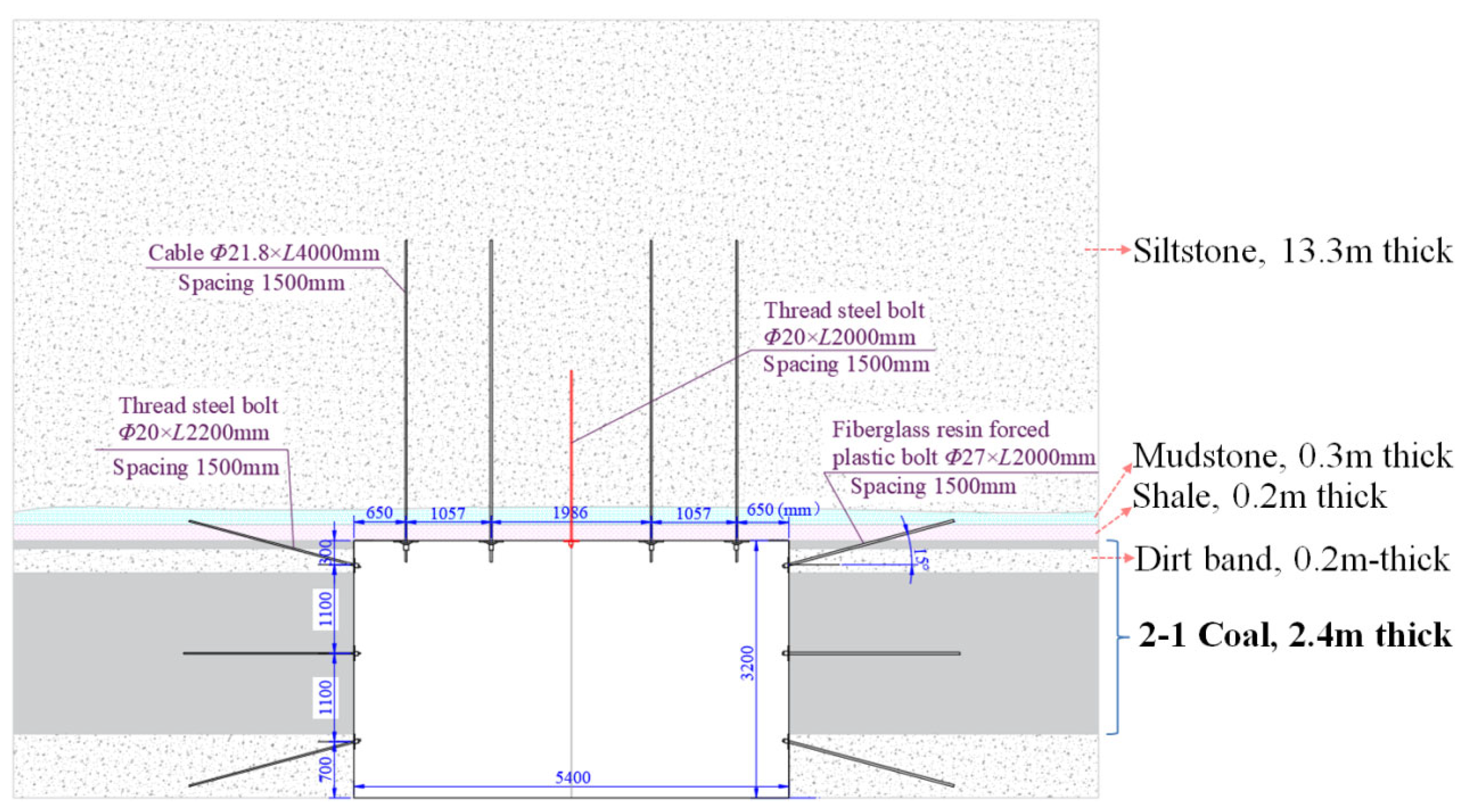
  • Bolt support: The roof is supported by six left-hand threaded steel bolts of Φ20 × 2200 mm in each row. The spacing between bolts is different, and the row spacing is 1000 mm. At the shoulder angle of roof, the bolts are installed at an outward tilt of 15°, and the remaining bolts are installed perpendicular to the roof. Each bolt is anchored by one MSK2350 mm resin cartridge and one MSCK2350 mm resin cartridge, and the pretension torque of each bolt is 100 N·m.
  • Cable support: Three cables with a diameter of 17.8 × 6200 mm are arranged every three rows of bolts on the roof to strengthen the support, and the cables are all installed perpendicular to the roadway roof. The spacing between cables is 1500 mm, and the row spacing is 3000 mm. Each cable is anchored by three MSK2350 mm resin cartridges, and the pretension force is 150 kN.
(2) Coal rib support
  • Non-mining rib: The non-mining rib of the roadway is supported by three left-hand threaded steel bolts of Φ20 × 2200 mm in each row. The spacing between bolts is 1100 mm, and the row spacing is 1000 mm. At the shoulder depression and bottom corner of the coal rib, the bolts are installed at an outward tilt of 15°, and the middle bolts are installed perpendicular to the rock surface. Each bolt is anchored by one MSK2350 mm resin cartridge and one MSCK2350 mm resin cartridge, and the pretension torque of each bolt is 100 N·m.
  • Mining rib: The mining rib is supported by three fiberglass bolts of Φ27 × 2000 mm in each row. The spacing between bolts is 1100 mm, and the row spacing is 1000 mm. At the shoulder depression and bottom corner of the coal rib, the bolts are installed at an outward tilt of 15°, and the middle bolts are installed perpendicular to the rock surface. Each bolt is anchored by one MSK2350 mm resin cartridge, and the pretension torque of each bolt is 100 N·m.

2.2.2. Maintenance Effect

The average buried depth of ARR 21204 is 650 m, the vertical stress is up to 16 MPa and the lithology of the roadway roof manifests variable occurrence, so this roadway belongs to the deep compound roof roadway category. During roadway driving, the surface displacement of surrounding rock is large, and the maximum displacement of the roof reaches more than 100 mm. Moreover, the displacement of the two ribs reaches more than 130 mm. The integrity of the roof rock strata affected by drilling is shown in Figure 3. The surrounding rock fractures and separation are relatively developed within 2 m of the roof, and there are still slight fractures at 3.1 m.

2.3. Problems

High-density bolts with a length of 2.2 m are used as the fundamental support on the roof, and low-density cables with a length of 6.2 m are used to strengthen the support. Due to the high density of the bolts, the foundation supporting composed of the 2.2 m-long bolts on the roof is crucial to the stability control of roof. As shown above, the surrounding rock fractures and separation are relatively developed within 2 m of the roof, and there are still slight fractures at 3.1 m. In other words, the development of separation fractures still exists both inside and outside the anchorage ring of foundation supporting, and the development degree of fractures decreases with the increase in roof depth.
The separation is caused by the discontinuous deformation of rock masses within and between the roof strata. The separation is the main cause of shear failure of bolts, obstruction of support stress transfer and loosening and collapse of rock mass. Therefore, it is crucial to make clear the discontinuous deformation law of roof rock mass and find the anchorage technology for controlling the discontinuous deformation of roofs.

3. Discontinuous Deformation Characteristics of the Deep Roadway Roof

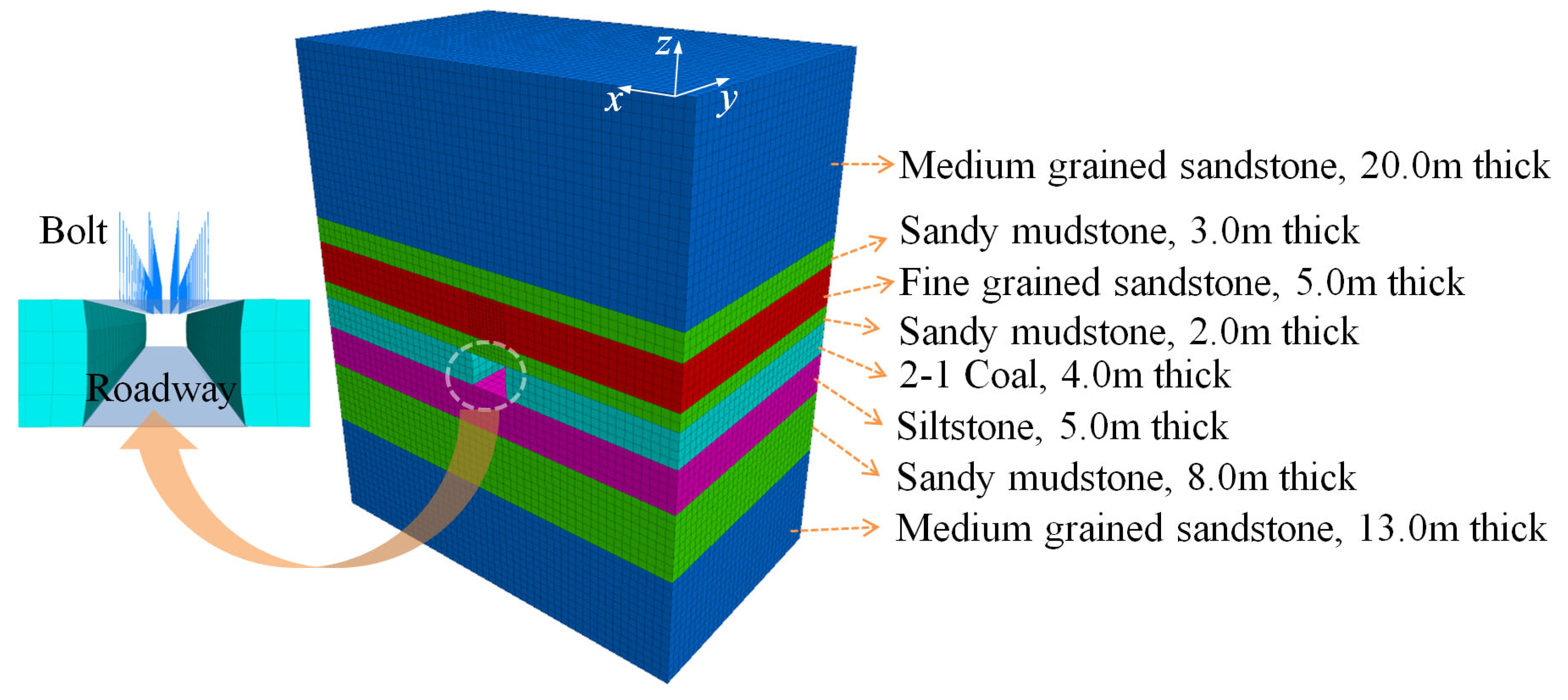
3.1. Model Establishment

To obtain the discontinuous deformation characteristics of the deep roadway roof through comparative analysis, the FLAC3D numerical calculation model of the roadway at different buried depths is established (Figure 4). Without loss of generality, this model is simplified and established on the basis of the engineering geological conditions of ARR 21204 in the Hulusu Coal Mine. Among four groups of roadway models, the buried depths of the coal seam are 200 m, 400 m, 600 m and 800 m, respectively. The thickness of the coal seam is 4 m, and the roadway size is width × height = 5 m × 4 m. The roadway is driven along the roof and floor of the coal seam. According to the section size of the roadway and the influence range of the heading face, the model size is selected as width (x) × height (z) × thickness (y) = 50 m × 60 m × 30 m. The model mesh size is width (x) × height (z) × thickness (y) = 1.0 m × 1.0 m × 1.0 m, and the mesh size near the roadway is refined (reduced by one times) to ensure the calculation accuracy.
The distance between the coal seam and the upper boundary of the model is 30 m, and the actual buried depth is simulated by applying an equivalent load (25 KPa/m) to the upper boundary of the model. Therefore, the vertical loads applied to the upper boundary of the roadway model at the buried depths of 200 m, 400 m, 600 m and 800 m are 4.3 MPa, 9.3 MPa, 14.3 MPa and 19.3 MPa, respectively, and the side pressure coefficient is taken as 1.0. The left, right and lower boundaries of the model are fixed by eliminating the displacement. The mechanical parameters of each rock stratum in the model are shown in Table 1. The Mohr-Coulomb criterion is adopted for operation calculation.

3.2. Discontinuous Deformation Characteristics of the Deep Roadway Roof

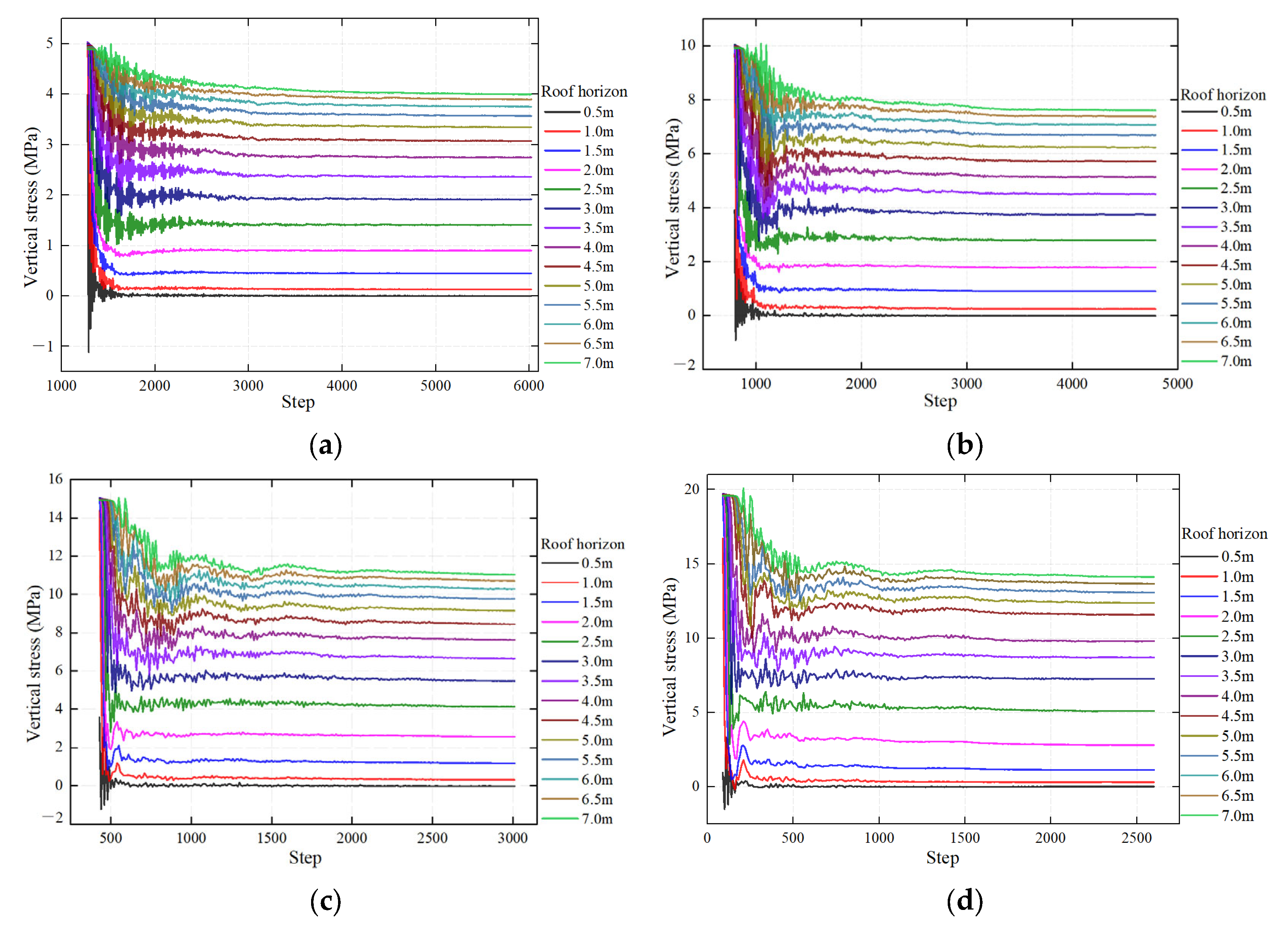
3.2.1. Stress Evolution Law of Rock Masses at Different Horizons of the Roadway Roof

(1) Simulation method
Calculation process: Calculate the original rock stress to initial balance first, then drive the ARR 21204 by 30 m at a time and calculate the stress balance.
Monitoring method: In order to monitor the stress evolution law of rock masses at different horizons of the roadway roof, 14 vertical stress monitoring points are arranged at 0.5 m, 1.0 m, 1.5 m, 2.0 m, 2.5 m, 3.0 m, 3.5 m, 4.0 m, 4.5 m, 5.0 m, 5.5 m, 6.0 m, 6.5 m and 7.0 m, respectively.
(2) Result analysis
The stress monitoring results of rock masses at different horizons of the roadway roof at different buried depths are shown in Figure 5, and the stress attenuation rates of rock masses at different strata are also shown in Figure 6. Therefore, it can be obtained:
a. After the excavation of the roadway, the stress of the rock mass within the monitoring range of the roadway roof at different buried depths is in an unloading state. The reason for this phenomenon is the stress readjustment and stress transfer of roof rock mass after roadway heading. The low stress zone of shallow roof rock mass is caused by the rock mass damage and energy storage decrease during the stress adjustment and transfer, which is in an unloading state.
b. The stress attenuation degree of the rock mass at different horizons of the roof is different, gradually decreasing with the rise of the rock mass horizon in the roadway roof. The stress attenuation rate of the rock mass within 2 m of the roof reaches more than 80%, and the stress attenuation rate of the rock mass above the roof stratum of 5 m gradually decreases to below 40%. Therefore, with the increase in roof depth, the effect on rock mass by heading and unloading disturbance is gradually weakened, and the stress unloading amplitude (stress attenuation rate) gradually decreases.
c. For the rock mass at the same roof stratum, the stress attenuation rate tends to increase with the increase in roadway buried depth. The larger the roadway buried depth, the higher the stress level. The range and intensity of the unloading disturbance to the roof rock mass by roadway heading accordingly increase.
Figure 5. Stress evolution of rock masses at different horizons of the roadway roof: (a) roadway at the buried depth of 200 m; (b) roadway at the buried depth of 400 m; (c) roadway at the buried depth of 600 m; (d) roadway at the buried depth of 800 m.
Energies 16 02160 g005
Figure 6. Stress attenuation rate of rock masses at different horizons of the roadway roof.
Energies 16 02160 g006

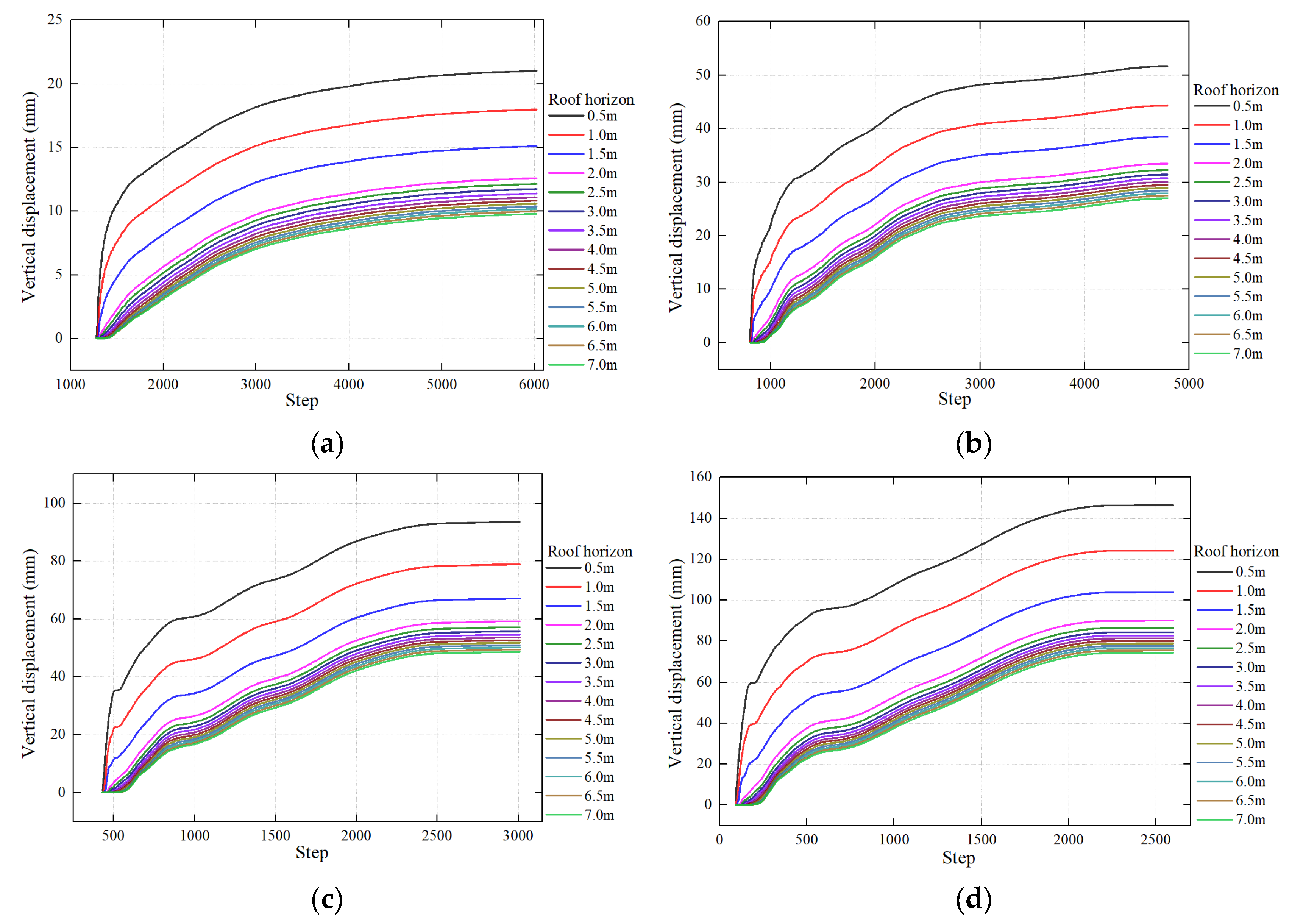
3.2.2. Displacement Distribution Law of Rock Mass in Different Roof Horizons

(1) Simulation method
Calculation process: same as above.
Monitoring method: In order to monitor the displacement evolution of the rock mass at different roof horizons of the roadway, 14 vertical displacement monitoring points are arranged at 0.5 m, 1.0 m, 1.5 m, 2.0 m, 2.5 m, 3.0 m, 3.5 m, 4.0 m, 4.5 m, 5.0 m, 5.5 m, 6.0 m, 6.5 m and 7.0 m, respectively.
(2) Result analysis
The displacement monitoring results of rock masses at different horizons of the roadway roof at different buried depths are shown in Figure 7. In order to display the uncoordinated and discontinuous deformation law between two monitoring points of the roof more intuitively, the displacement difference between the two monitoring points is defined as the degree of discontinuous deformation. The monitoring results are shown in Figure 8. Therefore, it can be obtained:
The displacement of rock masses on the roadway roof at different buried depths show the trend of gradual decrease from shallow to deep. For the rock mass within 0.5~2 m of the roof, the displacement is large; for the rock mass beyond the 2 m horizon of the roof, the displacement gradually decreases and tends to be stable.
The rock mass within the scope where the displacement difference of two monitoring points is larger than 2 mm is defined as the discontinuous deformation zone, and the rock mass within the scope where the displacement difference is smaller than 2 mm is defined as the continuous deformation zone. For the rock masses at different horizons of the roadway roof at the same buried depth, the degree of discontinuous deformation (separation fractures) tends to gradually decrease from shallow to deep. For the rock mass at the same horizon of roadway roof at different buried depths, the degree of discontinuous deformation (separation fractures) increases with the increase in the roadway buried depth.
The depth within the scope of the discontinuous deformation zone of the roadway roof increases with the increase in the roadway buried depth. When the buried depth of the roadway is 200 m or 400 m, the depth within the scope of the discontinuous deformation zone of the roof is 2 m; and when the buried depths of the roadway increase to 600 m or 800 m, the depths within the scope of the discontinuous deformation zone of the roof are increased to 2.5 m and 3.0 m, respectively.

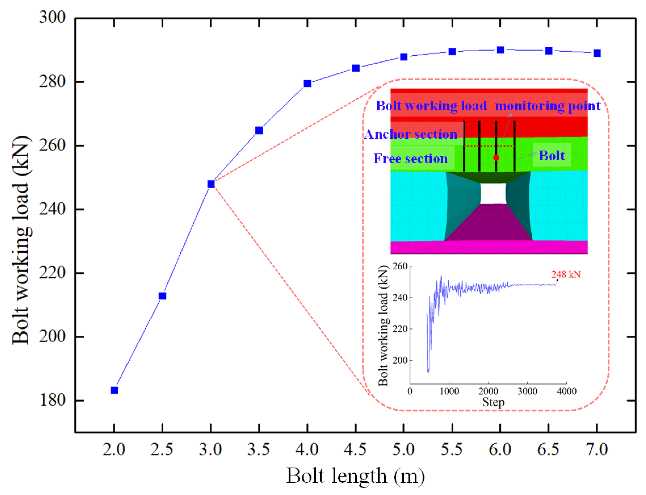
3.3. High Efficiency Bearing Characteristics of Bolt in Thick Anchorage Layer of Roof

(1) Simulation method
Calculation process: Select the numerical calculation model of the roadway at the buried depth of 600 m and calculate the original rock stress to initial balance, then drive the ARR 21204 by 30 m at a time, and at the same time carry out the bolt support of the roof and calculate the stress balance.
The bolt support is simulated by a cable unit. The prestressed bolt is simulated by controlling the different mechanical parameters of free sections and anchorage sections of the bolts. A total of seven supporting schemes with different anchorage thicknesses are set up. In these seven supporting schemes, four bolts are used for supporting in each row. The spacing between bolts is 1000 mm, and the row spacing is 1000 mm. The diameter of bolt is 22 mm and the prestress is 200 kN. The lengths of bolt are 2.0 m, 2.5 m, 3.0 m, 3.5 m, 4.0 m, 4.5 m, 5.0 m, 5.5 m, 5.5 m, 5.5 m, 6.0 m, 6.5 m and 7.0 m respectively, and the method of lengthening anchorage is adopted.
Monitoring method: In order to monitor the bearing characteristics of bolts with different anchorage thicknesses of roofs, a working load monitoring node was arranged in the middle of the free section of the second bolt on the right side of the same row of the roof, and its final stability value was recorded.
(2) Result analysis
The working load monitoring results of bolts with different anchorage thicknesses of roofs are shown in Figure 9. When the length of the bolt is 2.0–4.0 m, the load of the bolt increases rapidly with the increase in bolt length. Specifically, when the bolt length is 2.0 m, the load of the bolt is 183.3 kN; when the bolt length is increased to 4.0 m, the load of the bolt gradually increases to 279.5 kN, with a large increase range. When the length of the bolt is 4.0–5.5 m, the growth rate of the load of the bolt obviously decreases with the increase in bolt length; when the length of bolt exceeds 5.5 m, the load of the bolt will no longer show significant change.
The reasons for the above phenomenon are as follows: known from Figure 8, the depth within the scope of the discontinuous deformation zone of the roadway roof at the buried depth of 600 m is 2.5 m. In other words, the separation and fractures with a width of more than 2 mm, which are caused by great discontinuous deformation, exist in the rock mass within 2.5 m of the roof. When the length of bolt is smaller than 2.5 m, the bolt is within the development range of damage fractures in the roof, and the deformation difference of rock mass within the anchorage range of the bolt is small, the bearing performance of the bolt is poor and the working load is less than the pretension force (in order to adapt to the deformation of the shallow rock mass, the pretension force may in part be lost).
Since the rock mass displacement in the continuous deformation zone is small, the displacement difference between adjacent rock masses is also small (the degree of fracture damage is small), showing good integrity. When the length of the bolt is increased to 2.5–4 m, so as to pass through the discontinuous deformation zone to reach the continuous deformation zone, it mobilizes the deep rock mass to participate in bearing. Under this circumstance, the deformation difference of the rock mass within the anchorage range increases, and the load of the bolt increases accordingly. The deformation of the shallow rock mass is limited by the rapid increase in resistance.
When the length of bolt is further increased to 4.0–7.0 m, the displacement of the rock mass at the end of bolt tends to be stable. In other words, the displacement difference of the rock mass within the anchorage range tends to be stable [17], and the working load of the bolt will not change any more accordingly.

4. Cross-Boundary Linkage Control Principle of Thick Anchorage Layer

After roadway excavation, the rock masses at different shallow horizons of the roof have different degrees of stress attenuation and damage deformation, leading to the emergence of the discontinuous deformation zone of the rock mass. In the discontinuous deformation zone, the separation fractures of the rock mass are relatively developed. With the increase in roof depth, the degree of discontinuous deformation gradually decreases until the roof rock mass shows continuous deformation. With the increase in roadway buried depth (increase in stress level), the depth within the scope of the discontinuous deformation zone shows a tendency of progressive upward extension.
As revealed by the numerical simulation results, when the roadway buried depth is increased from 200 m to 400 m under specific conditions, the degree of discontinuous deformation of the shallow rock mass on the roof increases. In other words, the development degree of the separation fractures in the rock mass increases, but the depth within the scope of the discontinuous deformation zone is 2 m (Figure 10a,b). Then the bolts with a length of 2.0–2.5 m can enact a certain control effect on it. When the roadway buried depth is gradually increased to 600–800 m, the depth within the scope of the discontinuous deformation zone increases to 2.5–3 m (Figure 10c,d). Then the bolts with a length of 2.0–2.5 m are all in the discontinuous deformation zone, where the separation fractures are relatively developed. The bolt has a poor foundation strength and moves with the damaged shallow rock mass in the roof as a whole. The resistance cannot be increased in time to limit the deformation of the shallow rock mass, and the bearing efficiency of the bolt support is poor.
The support whose anchorage layer thickness is near the boundary of the damaged fracture zone of roof is called the critical support or in-boundary support. In this thin bearing zone, it is difficult to limit the progressive upward extension of the discontinuous deformation zone. In other words, it is difficult to limit the progressive damage failure of the shallow rock mass from shallow to deep. The separation fractures in the rock mass are relatively developed within the range of the anchorage zone, and the bearing efficiency of the bolt is low. Eventually, the accumulation of macroscopical deformation failures of the roof is large, and large deformation often occurs.
To solve this problem, an efficient cross-boundary linkage control technology of a thick layer is proposed. The principle of this technology holds that during roadway heading, a thick bearing layer of the roof should be constructed in time to cross the potential discontinuous deformation zone of shallow rock mass to reach the stable rock stratum of the deep continuous deformation zone, so as to increase the working load of the bolts (bearing performance of deformation with rapid increase in resistance). The small displacement of the stable rock mass in the deep continuous deformation zone is used to limit the large displacement of the rock mass with fracture damage in the shallow discontinuous deformation zone, so as to realize the large and small displacement linkage of the rock mass in the deep and shallow parts of the roof [25,26,27]. Thereby, it controls the progressive upward extension within the scope of the discontinuous deformation zone of the roof (Figure 11), therefore controlling the progressive damage failure of the rock mass from shallow to deep [28,29].

5. Industrial Test

5.1. Cross-Boundary Linkage Control Supporting Scheme of the Thick Anchorage Layer

(1) Roof support
Cables are used to build a thick layer of roof to support the roadway roof (Figure 12). It is supported by four cables of Φ21.8 × 4300 mm in each row. The cables are all installed perpendicular to the roadway roof. The spacing between cables from the first one to the fourth one on the left side is 1057 mm, 1986 mm and 1057 mm, respectively, and the row spacing is 1500 mm. Each cable is anchored by one CK2370 resin cartridge and one Z2370 resin cartridge, and the pretension force is 200 kN.
As the spacing between two cables in the middle of each row of roof is nearly 2.0 m and the shallow rock stratum is easily loosened and broken, one bolt of Φ20 × 2000 mm is constructed in the middle of every two rows of roof to strengthen the support.
(2) Coal rib support
The row spacing is increased from 1.0 m to 1.5 m on the basis of the original supporting scheme for the two coal ribs. The other parameters are consistent with the original supporting scheme, which will not be explained any more here.

5.2. Effect Analysis

5.2.1. Surface Displacement of the Roadway

The cross-section method is utilized to monitor the surface displacement of ARR 21204 under the cross-boundary linkage control supporting scheme of the thick anchorage layer. Two monitoring stations are arranged in total. Each monitoring station is arranged on the heading face of the roadway to monitor and record the surface displacement law of the roadway during the period from the disturbance of the bolt dynamic pressure to stability. The monitoring results are shown in Figure 13.
When the lag head is within 100 m, the roof subsidence and the displacement of the two ribs increase rapidly, basically showing a linear growth trend, in the heading disturbance stage. Then, as the working face continues to advance, the influence of the heading disturbance tends to be weak, and the displacement rate and displacement amount gradually tend to be stable. After stabilization, the monitoring results of these two monitoring stations show that the roof subsidence is within 10–12 mm and the displacement of the two ribs is within 12–16 mm. To conclude, the surface displacement of the roadway can be effectively controlled.

5.2.2. Monitoring of Fractures in the Roof Rock Stratum

In order to assess the development conditions of the roof fractures under the cross-boundary linkage control supporting technology of the thick anchorage layer, a high-definition peeping instrument is used to monitor the roof rock stratum by drilling holes. The monitoring results are shown in Figure 14.
Within 0.24~0.85 m of the roof, separation fractures with different degrees of breakage are developed, which are mainly in a circular shape. The roof rock mass at the depth of 0.85 m is relatively intact, and no separation fractures are found. Therefore, the cross-boundary linkage control supporting technology of the anchorage layer can use the small displacement of the rock mass in the deep continuous deformation zone to limit the large displacement of the rock mass in the shallow discontinuous deformation zone, so as to realize the size and displacement linkage of the rock mass in the deep and shallow parts of the roof. Furthermore, it limits the damage depth of roof fractures within the range of the shallow rock mass, and effectively controls the progressive upward extension of the discontinuous deformation zone.

5.2.3. Picture of Roadway Control Effect

The on-site picture of the roadway control effect is shown in Figure 15. The roadway roof and the coal ribs are relatively smooth, and breakage of the shallow coal and rock mass does not occur. To conclude, the control effect on the surrounding rock is good, and the stability of the surrounding rock is effectively guaranteed.

6. Conclusions

According to the deformation and failure law of the roof of the deep roadway, the characteristics of the discontinuous deformation of the roof of the deep roadway were studied and found. The technology of linkage control of thick layer cross-boundary anchorage was put forward pertinently, and the industrial test was carried out; the stability of the roadway roof has been greatly improved. From these studies, the following conclusions are drawn:
(1)
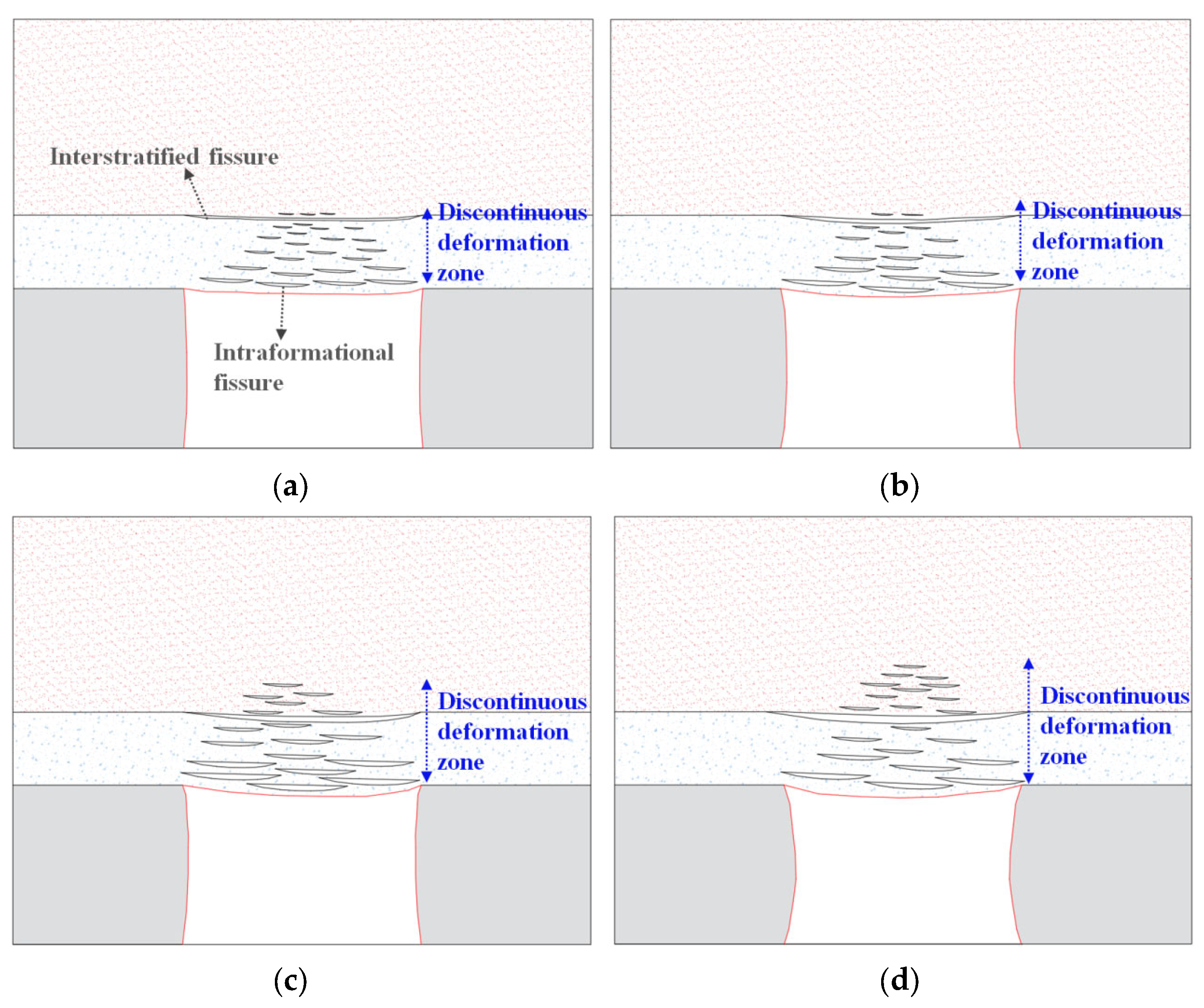
The discontinuous deformation degree and expansion range of the roof of the deep roadway are significantly increased. The excavation of the roadway leads to the stress unloading of the rock mass at different shallow horizons of the roof, resulting in the deformation of the rock mass. The stress attenuation degree and deformation degree of the rock mass at different horizons of roof are different, resulting in discontinuous deformation of rock mass. The degree of discontinuous deformation tends to gradually decrease from the shallow to the deep part of the roof until the continuous deformation zone with small deformation and stable rock strata appears. With the increase in the roadway buried depth, the discontinuous deformation degree of roof and its extended range show an increasing trend.
(2)
Bolt support in the thick anchorage layer can effectively improve the bearing capacity of the support. In the same roadway roof, increasing the length of the bolts (the thickness of the anchorage layer) can anchor the end of the bolts in the continuous deformation zone with small deep deformation and stable rock mass. As the deformation difference of the rock mass within the anchorage range of the bolt increases, the load of the bolt can rapidly increase to limit the deformation of the shallow rock mass. When the length of bolt is increased to a certain range, the displacement difference of the rock mass within the anchorage range tends to be stable, and the working load tends to be stable as well.
(3)
The cross-boundary linkage control technology of the thick anchorage layer was put forward. The construction of the thick anchorage layer of the roof can make the bolt cross the potential discontinuous deformation zone of the shallow rock mass to reach the stable rock strata in the deep continuous deformation zone. In other words, this technology uses the small displacement of the stable rock mass in the deep continuous deformation zone to limit the large displacement of the rock mass with fracture damage in the shallow discontinuous deformation zone. The linkage between the large and small displacements of rock mass can control the progressive upward extension of the discontinuous deformation zone of the roof, that is, control the progressive damage failure of rock mass from shallow to deep.
(4)
The industrial test on cross-boundary linkage control of the thick anchorage layer of the deep buried roadway roof was carried out. The results show that the deformation control effect on the roadway-surrounding rock is good; the deformation value of the roof when stable is less than 12 mm, and the displacement of the two ribs is less than 16 mm. Moreover, the scope of the discontinuous deformation zone (separation fracture zone) of the roof is controlled at the shallow horizon of 0.85 m, and no separation fracture is found in the deep rock mass, which effectively limits the progressive upward extension of the discontinuous deformation zone of the roof.

Author Contributions

Formal analysis, N.Z. and Q.Z.; Investigation, Q.Z. and K.S.; Writing—original draft, C.H. and H.Y.; Writing—review & editing, N.Z., H.Y. and K.S.; Funding acquisition, C.H. All authors have read and agreed to the published version of the manuscript.

Funding

This work was supported by the Fundamental Research Funds for the Central Universities (2019QNA23).

Data Availability Statement

Data is contained within the article.

Acknowledgments

The authors are very grateful to the reviewers for carefully reading the manuscript and providing valuable suggestions. The authors are also very grateful to Jihan Liu and Yongjin Huo of Zhongtian Hechuang Energy Co. Ltd. for their contributions in roadway pressure monitoring.

Conflicts of Interest

The authors declare no conflict of interest.

Abbreviations

ARR 21204air return roadway 21204

References

  1. Xie, H.P.; Ju, Y.; Ren, S.H.; Gao, F.; Liu, J.Z.; Zhu, Y. Theoretical and technological exploration of deep in situ fluidized coal mining. Front. Energy 2019, 13, 603–611. [Google Scholar] [CrossRef]
  2. Xie, H.P.; Gao, M.Z.; Zhang, R.; Peng, G.Y.; Wang, W.Y.; Li, A.Q. Study on the Mechanical Properties and Mechanical Response of Coal Mining at 1000m or Deeper. Rock Mech. Rock Eng. 2019, 52, 1475–1490. [Google Scholar] [CrossRef]
  3. Qi, Q.Q.; Pan, Y.S.; Li, H.T.; Jiang, D.Y.; Shu, L.Y.; Zhao, S.K.; Zhang, Y.J.; Pan, J.F.; Li, H.Y.; Pan, P.P. Theoretical basis and key technology of prevention and control of coal-rock dynamic disasters in deep coal mining. J. China Coal Soc. 2020, 45, 1567–1584. [Google Scholar]
  4. Chen, X.J.; Li, L.Y.; Wang, L.; Qi, L.L. The current situation and prevention and control countermeasures for typical dynamic disasters in kilometer-deep mines in China. Saf. Sci. 2019, 115, 229–236. [Google Scholar] [CrossRef]
  5. Zhan, Q.J.; Zheng, X.G.; Du, J.P.; Xiao, T. Coupling Instability Mechanism and Joint Control Technology of Soft-Rock Roadway with a Buried Depth of 1336 m. Rock Mech. Rock Eng. 2020, 53, 2233–2248. [Google Scholar] [CrossRef]
  6. Yang, H.Q.; Han, C.L.; Zhang, N.; Pan, D.J.; Xie, Z.Z. Research and Application of Low Density Roof Support Technology of Rapid Excavation for Coal Roadway. Geotech. Geol. Eng. 2020, 38, 389–401. [Google Scholar] [CrossRef]
  7. Mandal, P.K.; Das, A.J.; Kumar, N.; Bhattacharjee, R.; Tewari, S.; Kushwaha, A. Assessment of roof convergence during driving roadways in underground coal mines by continuous miner. Int. J. Rock Mech. Min. Sci. 2018, 108, 169–178. [Google Scholar] [CrossRef]
  8. Alejano, L.R.; Taboada, J.; Garcia-Bastante, F.; Rodriguez, P. Multi-approach back-analysis of a roof bed collapse in a mining room excavated in stratified rock. Int. J. Rock Mech. Min. Sci. 2008, 45, 899–913. [Google Scholar] [CrossRef]
  9. Hebblewhite, B.K.; Lu, T. Geomechanical behaviour of laminated, weak coal mine roof strata and the implications for a ground reinforcement strategy. Int. J. Rock Mech. Min. Sci. 2004, 41, 147–157. [Google Scholar] [CrossRef]
  10. Ma, N.J.; Zhao, X.D.; Zhao, Z.Q.; Li, J.; Guo, X.F. Stability analysis and control technology of mine roadway roof in deep mining. J. China Coal Soc. 2015, 40, 2287–2295. [Google Scholar]
  11. Li, J.; Peng, B.; Yuan, P. A formation mechanism of “low resistance and slight change” in plastic zone of butterfly leaf on the roof in deep roadway. J. Min. Saf. Eng. 2019, 36, 465–472. [Google Scholar]
  12. Yuan, Y.X.; Han, C.L.; Zhang, N.; Feng, X.W.; Wang, P.; Song, K.; Wei, M. Zonal Disintegration Characteristics of Roadway Roof Under Strong Mining Conditions and Mechanism of Thick Anchored and Trans-boundary Supporting. Rock Mech. Rock Eng. 2022, 55, 297–315. [Google Scholar] [CrossRef]
  13. Mazurek, K.; Szygula, M.; Figiel, A.; Filipowicz, K. Continuous Support for Roadways. Energies 2021, 14, 5801. [Google Scholar] [CrossRef]
  14. Zuo, J.P.; Wen, J.H.; Hu, S.Y.; Zhao, S.K. Theoretical model and simulation study of uniform strength beam support in deep coal mine roadway. J. China Coal Soc. 2018, 43, 1–11. [Google Scholar]
  15. Zuo, J.P.; Wen, J.H.; Liu, D.J.; Wu, L.L.; Sun, Y.J. Control theory of uniform strength support in deep roadway. J. Min. Sci. Technol. 2021, 6, 148–159. [Google Scholar]
  16. Kang, H.P.; Li, J.Z.; Yang, J.H.; Gao, F.Q. Investigation on the Influence of Abutment Pressure on the Stability of Rock Bolt Reinforced Roof Strata Through Physical and Numerical Modeling. Rock Mech. Rock Eng. 2017, 50, 387–401. [Google Scholar] [CrossRef]
  17. Colwell, M.; Frith, R. Utilising the scientific method to demonstrate that slender beam/column behaviour is the dominant behavioural mechanism leading to roof/rib failure. Int. J. Min. Sci. Technol. 2021, 31, 867–887. [Google Scholar] [CrossRef]
  18. Xie, Z.Z.; Zhang, N.; Yuan, Y.X.; Xu, G.; Wei, Q. Study on Safety Control of Composite Roof in Deep Roadway Based on Energy Balance Theory. Sustainability 2019, 11, 3688. [Google Scholar] [CrossRef] [Green Version]
  19. An, Y.P.; Zhang, N.; Zhao, Y.M.; Xie, Z.Z. Field and numerical investigation on roof failure and fracture control of thick coal seam roadway. Eng. Fail. Anal. 2021, 128, 105594. [Google Scholar] [CrossRef]
  20. Jia, P.; Zhu, W.; Zhang, S. Effect of heterogeneity on occurrence of zonal disintegration around deep underground openings. Int. J. Min. Sci. Technol. 2014, 24, 859–864. [Google Scholar] [CrossRef]
  21. Wu, H.; Guo, Z.; Fang, Q.; Zhang, Y.; Liu, J. Mechanism of zonal disintegration phenomenon in enclosing rock mass around deep tunnels. J. Cent. South Univ. Technol. Engl. Ed. 2009, 16, 303–311. [Google Scholar] [CrossRef]
  22. Wu, Q.S.; Jiang, L.S.; Wu, Q.L.; Xue, Y.C.; Gong, B. A study on the law of overlying strata migration and separation space evolution under hard and thick strata in underground coal mining by similar simulation. Dyna 2018, 93, 175–181. [Google Scholar] [CrossRef] [PubMed] [Green Version]
  23. Tan, Y.L.; Zhao, T.B.; Xiao, Y.X. Researches on floor stratum fracturing induced by antiprocedure mining underneath close-distance goaf. J. Min. Sci. 2010, 46, 250–259. [Google Scholar] [CrossRef]
  24. Jiang, Z.W.; Wang, Q.Y. Risk Assessment on Ground Fissure Disasters of Xi’an Metro Line 3. Adv. Mater. Res. 2011, 255–260, 3841. [Google Scholar] [CrossRef]
  25. Yang, H.Q.; Han, C.L.; Zhang, N.; Sun, Y.T.; Pan, D.J.; Sun, C.L. Long High-Performance Sustainable Bolt Technology for the Deep Coal Roadway Roof: A Case Study. Sustainability 2020, 12, 1375. [Google Scholar] [CrossRef] [Green Version]
  26. Zhang, N.; Han, C.L.; Xie, Z.Z. Theory of continuous beam control and high efficiency supporting technology in coal roadway. J. Min. Strat. Control Eng. 2019, 1, 48–55. [Google Scholar]
  27. Xie, Z.Z.; Zhang, N.; Feng, X.W.; Liang, D.X.; Wei, Q.; Weng, M.Y. Investigation on the evolution and control of surrounding rock fracture under different supporting conditions in deep roadway during excavation period. Int. J. Rock Mech. Min. Sci. 2019, 123, 104122. [Google Scholar] [CrossRef]
  28. Yang, H. Experimental Study on Mechanical Properties of Fully Bonded Bolts with Varied Bond Length. Geotech. Geol. Eng. 2022, 40, 4083–4094. [Google Scholar] [CrossRef]
  29. Xie, Z.; Zhang, N.; Han, C.; An, Y. Research on principle and application of roof thick layer cross-boundary anchorage in coal roadways. Yanshilixue Yu Gongcheng Xuebao/Chin. J. Rock Mech. Eng. 2021, 40, 1195–1208. [Google Scholar] [CrossRef]
Figure 1. Layout of the working face and roadway location.
Energies 16 02160 g001
Figure 2. Original supporting scheme.
Energies 16 02160 g002
Figure 3. Distribution of roof separation fractures in ARR 21204.
Energies 16 02160 g003
Figure 4. Modeling.
Figure 4. Modeling.
Energies 16 02160 g004
Figure 7. Displacement evolution of rock masses at different horizons of the roadway roof: (a) roadway at the buried depth of 200 m; (b) roadway at the buried depth of 400 m; (c) roadway at the buried depth of 600 m; (d) roadway at the buried depth of 800 m.
Energies 16 02160 g007
Figure 8. Displacement difference of rock masses at different horizons of the roadway roof.
Energies 16 02160 g008
Figure 9. Distribution of the working load of the bolt with different anchorage thicknesses of roofs.
Energies 16 02160 g009
Figure 10. Distribution law of the discontinuous deformation zone of the roadway roof at different buried depths: (a) roadway at the buried depth of 200 m; (b) roadway at the buried depth of 400 m; (c) roadway at the buried depth of 600 m; (d) roadway at the buried depth of 800 m.
Energies 16 02160 g010
Figure 11. Cross-boundary linkage control technology of the thick anchorage layer of the roof: (a) roadway roof not supported at the buried depth of 600 m; (b) thick anchorage layer of the roadway roof supported at the buried depth of 600 m.
Energies 16 02160 g011
Figure 12. Cross-boundary linkage control supporting scheme of the thick anchorage layer.
Energies 16 02160 g012
Figure 13. Surface displacement law of the roadway under the new supporting technology: (a) monitoring results of monitoring station 1; (b) monitoring results of monitoring station 2.
Energies 16 02160 g013
Figure 14. Distribution of separation fractures in the roadway roof under the new supporting technology.
Energies 16 02160 g014
Figure 15. Picture of the roadway maintenance effect: (a) roadway roof; (b) roadway coal rib.
Energies 16 02160 g015
Table 1. Rock occurrence and mechanical parameters.
NumberLithologyThickness (m)Density (kg·m−3)Bulk Modulus (GPa)Shear Modulus (GPa)Internal Friction Angle (°)Cohesion
(MPa)
Tensile Strength (MPa)
4Medium grained sandstone20.025983.51.830.01.31.6
3Sandy mudstone3.024004.63.235.02.02.5
2Slight grained sandstone 5.026353.01.628.01.51.5
1Sandy mudstone2.024004.63.335.02.02.5
03-1 Coal4.012911.30.325.01.10.5
−1Siltstone5.025673.01.628.01.53.9
−2Sandy mudstone8.024004.63.235.02.02.5
−3Medium grained sandstone13.025983.51.830.01.31.6
Disclaimer/Publisher’s Note: The statements, opinions and data contained in all publications are solely those of the individual author(s) and contributor(s) and not of MDPI and/or the editor(s). MDPI and/or the editor(s) disclaim responsibility for any injury to people or property resulting from any ideas, methods, instructions or products referred to in the content.

