Abstract
The design of hydrokinetic plants in hydropower canals involves the choice of the array layout, rotor geometry, turbine spacing, and array spacing, and necessitates the control of the resultant backwater to avoid upstream flooding hazards. Several works in the literature have shown that array power optimization is feasible with small spacings between the arrays, disregarding the limitation in the power output induced by backwater upstream. In this study, a 1-D channel model with a Double Multiple Streamtube code and wake sub-models are integrated to predict an array layout that will maximize the array power. The outputs of the conducted sensitivity analysis confirm that this design enabled improved power conversion with closely spaced turbines and largely spaced arrays, thus allowing for a partial recovery of the total head variation for a new array deployed upstream. In addition to the quantitative assessment of the mechanical power converted, the tool enables depth control from the downstream undisturbed flow station to the backwater exhaustion far upstream, thereby increasing its flexibility. Furthermore, it overcomes the limitations of actuator disc models by considering rotor’s fluid dynamic losses. The results show that power output linearly scales for a limited number of arrays (≤5), whilst the variation in water depth variation follows a power law from the most downstream array towards upstream, regardless of the plant size. Finally, the maximum upstream inflow depth is demonstrated to become asymptotic for large multi-array plants under ideal conditions.
1. Introduction
The idea of integrating existing hydropower plants with hydrokinetic turbines was suggested by Liu and Packey [1] for the development of Combined-Cycle Hydropower Systems, for which the objective was to harvest additional energy from the tailwater of the flows exiting dams.
The energy recovery of hydropower canals was then discussed by Cacciali et al. [2] to attempt the installation of cross-flow HK devices in inlet hydropower canals, i.e., artificial waterways connecting basins with a subcritical flow, with lateral banks that conveniently accommodate structural works. This application is suitable in some parts of northern Italy, which is a mountainous area with several hydroelectric plants built more than a hundred years ago. An example of a hydro–hydro application is illustrated in Figure 1 concerning the rotors being tested by HE Powergreen S.r.l. [3] in the Biffis canal, i.e., a waterway used to supply the hydropower plant in Bussolengo (VR), Italy.
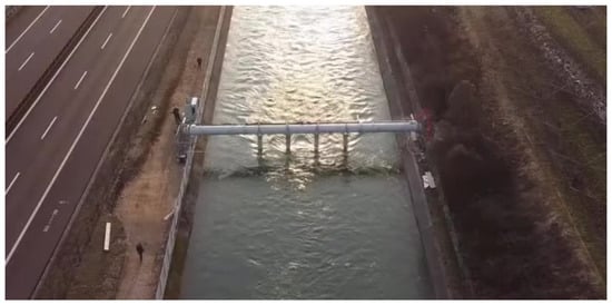
Figure 1.
An array of aligned vertical-axis cross-flow hydrokinetic turbines deployed in a regular canal. Image from HE Powergreen S.r.l. [3].
The deployment of multiple arrays represents a trade-off between power optimization and environmental control. Indeed, besides the energy harvested, an adverse effect is posed by the backwater generated from the operating turbines, thus implying the requirement for automated depth measurement. This forces the designer to strictly design the array such that it limits the backwater induced by the plant. On the other hand, the basin operator cannot allow flooding hazards to occur due to faulty design.
The most relevant works intended for canals and fluvial applications are presented in the following material; some of these are dedicated to array power optimization in tidal flows, including assessments of turbine spacing and array spacing.
Turbine arrays were investigated by Gauvin-Tremblay and Dumas [4] in aligned and staggered configurations; the investigation showed that the local blockage and turbine–wake interaction affect the performance of an array, which, in turn, dominates the downstream row. The wake deflection originating from the upstream vertical-axis turbines highlighted a negative impact on the staggered configuration and clarified that an aligned layout with inward rotations of the turbines should be selected. Their work demonstrated no advantages in terms of power extraction for the aligned configuration over a staggered layout in a wide channel, whilst higher power output was shown by the aligned configuration in a narrower environment. The authors also observed higher mean power extraction per turbine by increasing the longitudinal spacing between the turbine arrays; however, they also affirmed that the larger the lateral spacing, the higher the total power. Almost all the aforementioned results were confirmed by the model presented in our work, except for those regarding lateral spacing, as will be clarified later.
Gonzalez-Gorbeña et al. [5] conducted an interesting optimization of turbine arrays with a surrogate-based method for regular and irregular channels in both uniform and non-uniform flow scenarios. Inline and staggered arrays were investigated, leading to the determination of capacity factors and profitability. Polynomial and radial basis function surrogate methods were used to fit an objective function based on two variables: the lateral and the longitudinal spacings. This method is promising, although the downstream flow does not seem to affect the upstream flow, wherein horizontal rotors were simplified as actuator discs.
Okulov et al. [6] tested longitudinally aligned horizontal axis hydrokinetic turbines with particle image velocimetry to measure the flow properties upstream and downstream of the devices including up to four elements, highlighting the interference of the turbine wake on the downstream turbine, which was closely deployed. The authors remarked on a continuous drop in turbine performance due to the upstream wake reducing the inflow speed with higher turbulence. Unlike Okulov, we clarify that optimal rotor placement in a narrow canal or riverbed should enable the rotor’s detachment from reduced longitudinal spacings due to turbulent phenomena. This was clarified through the on-site experience of H.E. Powergreen S.r.l. [3], which demonstrated evident backwater phenomena due to the variation in rotor speed and lateral spacing.
Septyaningrum et al. [7] investigated co-rotating and counter-rotating turbines and conducted an analysis of turbulence intensity in the interaction zone, thereby demonstrating that flow superposition is not the only reason for flow acceleration, as an additional influence is contributed by a closer spacing between the turbines, which confers a jet-type flow effect for the bypass flow. The authors proved that a faster velocity superposition and lower turbulence intensity are achieved with inward counter-rotating rotors. Although not discussing the backwater phenomenon, the authors indicated that the performance of downstream turbines in a multi-array layout would be sub-optimal if operating in the wake of upstream turbines, concluding that downstream turbines should be placed beyond that area.
Riglin et al. [8] simulated different array layouts with a CFD solver based on RANS equations mimicking a hydro-farm. A substantial drop in power was observed from the upstream to downstream units, showing that the operation of a turbine in the wake of the upstream turbines significantly reduces the energy available downstream.
Vennell et al. [9] reviewed the main parameters affecting the large turbine arrays in tidal flows, highlighting that the enhanced drag due to power extraction reduces the mean flow speed as the flow approaches the rotors. Moreover, the authors specified that optimally tuned turbines in large arrays perform differently from tuned isolated turbines. Some of the effects of a large array discussed by Vennell can be applied to on-land subcritical canals, e.g., in efforts to boost a turbine’s output by adjusting its relative position within an array. In this work, this effect is obtained by modifying the spacing between the turbines. Vennell indicated that higher capacities can be obtained by adding supplementary turbines to an array, but the behavior of the power curve differs among wide and narrow channels.
A major contribution to array-based analytical models can be attributed to Nishino, Willden, and Draper, whereas the confined actuator disc theory was extended in its free surface double-disc version in our previous work [10], which was subsequently updated with a method accounting for the backwater in subcritical flows [2].
Although staggered turbine layouts have been assessed in relation to tidal flows [11,12,13], their actual application in hydropower canals is questionable, as closely spaced rows would cause an increase in turbulent effects and hydrostatic depth, which is only tolerable to a small extent, and which will be explained further later. With aligned rotors, the hydraulic transition to be solved at each turbine array resembles the solution introduced by Cacciali et al. [2]. Once the equilibrium in hydrostatic pressure is reached upstream of each turbine array, the computation of the average flow speed in the cross-section is iteratively feasible. Since the maximum power output can be reached by respecting the environmental constraints, i.e., avoiding overbank flows due to backwater, only aligned rotors are investigated.
Nishino and Willden [11,12] described the flow disturbance due to multiple turbines involving a large portion of the channel. The flow proximity was ideally assessed on a large scale with actuator discs due to power extraction in a tidal environment, showing that the turbine-scale wake expansion occurs faster than the expansion around the turbine array. Draper and Nishino [13] developed a model for centered and staggered actuator discs and concluded that two arrays should be closely spaced only if staggered; otherwise, centered arrangements should be kept as far apart as possible, which is in agreement with our findings. Subsequently, a theoretical model accounting for both the turbine and array scales was introduced by Vogel et al. [14] for a finite-width array of tidal turbines. However, these analytical approaches are controversial if applied to narrow canals of an arbitrary cross-sectional geometry when a subcritical flow is subject to downstream control.
Since undisturbed subcritical flow occurs downstream of any hydraulic resistance [15], a reference flow speed U∞ can be designated for performance and axial force computations. Alternatively, the use of the inflow speed U0 instead of U∞ at the denominator would complicate the assessment as multiple and contemporary flow speed measurements and data processing would be required at each cross-section. Indeed, the turbine thrust coefficient and the power coefficient are better defined as CT,∞ = T/(½ρATU∞2) and CP,∞ = P/(½ρATU∞3), with ρ denoting the water density, T denoting the turbine thrust force, P representing the mechanical power, AT denoting the rotor swept area, and U∞ representing the far-field flow speed. The array thrust coefficient and power coefficient are given by CTA,∞ = TA,i/(½ρAarrayU∞2) and CPA,∞ = PA,i/(½ρAarrayU∞3), respectively, with TA,i and PA,I denoting the thrust force and power developed at the ith array, and Aarray denoting the array’s transversal area. Since U∞ is constant in a steady flow and is uniquely determined before any assessment, it is preferable to relate the dimensionless coefficients to the undisturbed flow [2].
The hydraulic transition due to the turbine array entails free surface deformation in canals, waterways, and rivers, with a cross-section almost entirely occupied by cross-flow or axial-flow hydrokinetic turbines. In a previous study, Myers and Bahaj illustrated the free surface effects achieved experimentally in water channels at various speeds [16]. Moreover, the variation in the clearance between the top of the turbine and the still water level can also create undesirable phenomena, as clarified further on.
The potential for hydrokinetic energy exploitation has been determined in several works [17,18,19,20,21], with most of them estimating the total head variation in a certain section of the channel without introducing a turbine model. These assessments offer an undoubtable advantage in terms of simplicity and allow for direct access to data when designing hydrokinetic systems.
However, a rigorous estimation of this potential that accounts for the free surface development in the investigated canal stretch has not yet been provided. Due to the complexity and computational cost of the numerical works conducted with CFD simulations on turbine arrays, estimates of the available capacity and effective power output in a simple, quick, and effective manner are rare. In addition, analytical models only provide a macroscopic picture of the energy extraction in water flows that do not differentiate each turbine in the array [4]. We agree that analytical models concerning ideal actuator discs draw interesting conclusions regarding the layouts of the arrays, but they do not include important aspects of turbine operation and turbine–wake interaction. This fact prompted us to consider designing a model that overcomes the limitations of the actuator discs, i.e., including the fluid-dynamic losses of each turbine, and avoiding the excessive computational costs necessitated by CFD models.
Therefore, a tool that quantitatively estimates the exploitable resources in a canal to pre-size the hydrokinetic plant was developed, which incorporated the complete prediction of the free surface variation induced by the rotors from a uniform station (downstream) to the exhaustion of the backwater (far upstream). This has not been presented in other works. Moreover, different prismatic channel geometries can be considered, thus adding flexibility to the simulation.
Real rotors are predicted by this tool, thus overcoming the limitations concerning the approximation of ideal rotors with actuator discs. The fluid flow distant from each rotor is then simplified as a 1-D channel flow based on a subcritical hydraulic regime, i.e., respecting the physics of open channel flows.
However, based on momentum models, this tool does not allow for the direction of rotation of the rotors to be distinguished, nor does it allow for the mutual influence of the wakes to be evaluated. The treatment of the development of wakes is executed by exploiting regressions, and this simplifies the modeling process because power dissipation is treated quantitatively. It is emphasized that the method requires that the wake of an upstream array does not affect the fluid dynamics of the downstream array. Indeed, on an industrial scale, the array problem should be treated over a consistent longitudinal stretch. Unlike some of the cited works, the deployment of rotating elements in the wake of other rotors for systems designed over long, longitudinal stretches seems illogical. For design purposes, it is critical to ensure sufficient longitudinal spacing to recover, albeit partially, the velocity and depth of the flow.
The integrated use of a DMS model for vertical-axis turbines [10] with a hydraulic model for solving the hydraulic transition for single rotors [2], the computation of the level of backwater generation [22], and a simplified investigation of the recovery length downstream of the array from the research in [23,24] enable the rapid prediction of the available and exploitable capacity.
By incorporating these methods, this work aims to model multiple arrays with a numerical procedure with a low computational cost, thus obtaining the expected CT,∞ and CP,∞ of equal turbines in canals of a prismatic shape. With the help of tests performed at the Unitn Hydraulics Laboratory on plates immersed in a water channel, theoretical insights on the asymptotic trend of the maximum backwater from array to array are discussed.
The proposed method is introduced in a single-array and multi-array scheme, which are presented in Section 2.1 and Section 2.2, respectively. Section 2.1.1 includes the definitions of turbine and array blockage ratios, whereas Section 2.1.2 presents an optimization scheme with which to build the power curve of a single turbine and select the best performance at the optimum tip speed ratio. This procedure is repeated for all turbines in the array. When the turbine’s thrust and power are determined, the total thrust force of the array relaxes the inflow blockage and Froude number. Once converged, the code updates each rotor’s power and thrust force. Hence, a scheme between M1 and M2 must be selected. According to scheme M1, an equal rotor speed is assumed for all turbines in the array; according to scheme M2, each turbine is optimized at a certain rotor speed, implying higher array power.
Eventually, an environmental boundary condition can be activated (Section 2.1.3) to limit the backwater to a prescribed depth variation. Section 2.1.4, Section 2.1.5, and Section 2.1.6 are dedicated to the approximation of the near-wake, transition-wake, and far-wake past the turbines. Hence, Section 2.1.7 shows the methods for estimating the reduction in the backwater upstream according to energy or momentum principles.
The results discussed in Section 3 focus on sensitivity analysis (Section 3.1), array design (Section 3.2), and simulations of large plants (Section 3.3). First, a sensitivity analysis is performed concerning turbine spacing and then regarding array spacing for a plant built with four arrays and four turbines per array. The simulations dedicated to the array design in Section 3.2 show the best prediction within a selected number of cases based on a constant blockage ratio and a fixed level of rotor solidity, thereby enabling a reduction in the number of variables. The inclusion of a limit in the backwater would alter the output of this prediction, thus directing the design toward less-expensive and lower-power solutions. Section 3.3 shows the expected free surface variation from a simulation performed for a plant of many arrays. Finally, conclusions and prospects are discussed in Section 4.
2. Methods
In this study, a canal of a double-trapezoid cross-section was investigated to perform simulations with the multi-array optimizer, which initially employed undisturbed flow data (U∞, h∞, and Fr∞). A Manning’s coefficient n of 0.031 at a certain cross-section was calibrated with a design flow rate Qc of 124 m3/s, depth h∞ = 6.52 m, and local bed slope S of 3.84 × 10⁻⁴, along with a determination of the bulk flow speed U∞ (1.439 m/s) and Froude number Fr∞ (0.223). Geometric details of the cross-section depicted in Figure 2 were retrieved from Malini [25]. Technical data were drawn from local sources with authorization and are not disclosed in this work. The Froude number is calculated as Fr∞ = U∞(gA∞/w∞)−1/2, with U∞ denoting the mean far-field flow speed, A∞ representing the transversal wetted area, w∞ denoting the free surface width, and g denoting gravity acceleration.
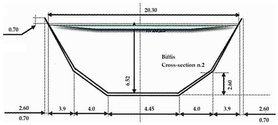
Figure 2.
Cross-section of interest in the Biffis canal from Malini [25], which was modified according to the design specifications of this work.
2.1. Single-Array Scheme
Generally, acoustic doppler velocimetry (ADV) and subsequent data processing at different times allow for flow speed to be averaged spatially and over time. In case of data scarcity, entropy methods [26] offer a reliable alternative for the achievement of the mean flow speed in ungauged streams. Indeed, investigations [27,28] have demonstrated that the entropy parameter does not depend on energy or friction slope Sf. This justifies why the mean value of the entropy parameter at gauged sites remains approximately constant regardless of the level of discharge.
The far-field blockage generated by a turbine array BA,∞ is given by the sum of the turbines’ swept area divided by the wetted area (1).
BA,∞ = NT AT/A∞
Considering a single-turbine array with multiple rotors aligned orthogonally to the direction of the flow, all flow passages are modeled as independent tubes (Figure 3) sharing equal flow conditions upstream {0} and downstream {∞}, similar to the model depicted in [9].
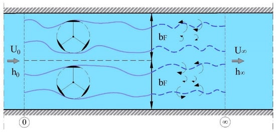
Figure 3.
Control volume of an array of aligned HK turbines in a channel flow.
Each turbine wake is shaped by its flow passage, which, in turn, is bounded by the adjacent tubes and canal walls. The hydrostatic velocity profile is imposed for all tubes to allow the DMS code to be applied. The wetted area in {0} is divided into flow passages from the canal wall to half of the horizontal spacing turbine dT or from a centerline to another centerline, as further illustrated in Figure 4. According to Vogel et al. [14], the turbine blockage is given by Equation (2), with AF,j denoting the flow passage associated with the jth turbine, from left to right, and AT,j denoting the turbine’s swept area.
BT,j = AT/AF,j
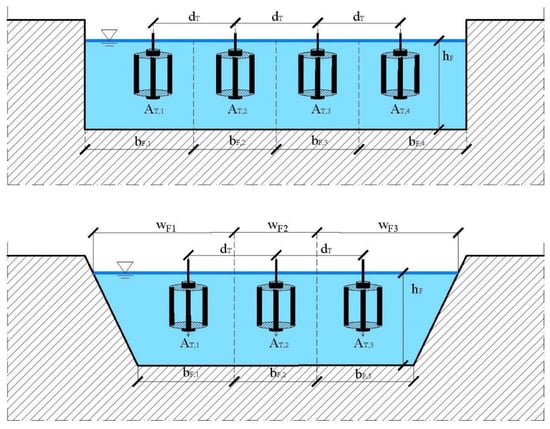
Figure 4.
Flow passages determined for multiple HK turbines.
In this work, an array-scale blockage is built with different flow passages based on the canal cross-section geometry, which is unlike Vogel’s method for tidal turbines. As can be seen in Figure 1, the larger wake released by side rotors suggests that greater blockage is attributable to the rotors deployed at the center of the canal. Since equal blockage for all turbines is feasible only for arrays in wide (and rectangular) channels, this assumption is henceforth discarded.
If the array consists of two rotors symmetrically dividing the wetted area A0, both DMS simulations would predict the same outputs. Otherwise, different values of BT,j would lead to an uneven distribution of thrust and power outputs for the turbines. Figure 4 shows examples of the subdivision of flow passages, in which higher blockage is assigned centrally, and lower blockage is assigned laterally. The inflow speed is assumed to be uniformly distributed upstream of the station {ith}. For a wide cross-section in navigable waterways, the array can be positioned on a side of the channel, resulting in an asymmetrical distribution of the flow through, but this case is not discussed in this work for the sake of brevity.
2.1.1. Iterative Scheme for a Single-Array
In this work, a procedure valid for the entire turbine fence is derived, whilst the scheme for a single rotor is explained in [2]. The inflow factor ϕ = U0/Uref is defined in a domain 0 < ϕ ≤ 1, while the ith array blockage ratio (3) and Froude number (4) are scaled from BA,ref and Frref to iteratively solve the hydraulic transition. Notably, for the first array from downstream Uref = U∞, Frref = Fr∞ and BA,ref = BA,∞, but for the additional arrays, the downstream flow is represented by a reference station, which is simply indicated as “ref”. The array thrust coefficient CTA,ref, i.e., the ratio of the resultant thrust force generated over the entire structure to the reference dynamic pressure force (5), is used to solve the degree of momentum conservation between upstream and downstream stations {0, ref}, whose equation is given in (6).
BA = ϕ/BA,ref
Fr = ϕ3/2 (w0/wref)1/2 Frref
CTA,ref = TA/(½ ρ Uref2 NT AT)
2Frref2 ϕ3 − (CTA,ref BA,ref Frref2) ϕ2 + 1 = 0
The resultant force is the sum of the individual forces, i.e., TA = ∑Tj. Notice that the array area NT × AT appears at the denominator in (5). Hence, the cubic polynomial (6) must be solved numerically for ϕ once CTA,ref is determined, as BA,ref, and Frref are known. This mathematical statement holds for a single turbine and multiple turbines as well, but in this case, array blockage and the resultant axial force are used instead. The DMS model [10] is applied repeatedly for each turbine so that CTA,ref is attained after the accumulation of all thrust forces. The updated solution of (6) is used to yield the new Uref, Bref, and Frref. According to the canal’s shape, a continuity equation must be solved to achieve w0 and thus Fr, as illustrated in Table 1 of [2], whilst the whole cycle is repeated until the convergence of the inflow factor ϕ. To investigate the flow speed variation from the most upstream array to downstream, a global inflow factor ϕg is also defined as U0/U∞.
2.1.2. Power Optimization Schemes
The need for an environmental check may be imposed by the channel manager or by specific regulations requiring the operator to minimize the increase in hydrostatic level upstream of the whole plant. Therefore, an additional flag is introduced, which, if activated, reduces the rotor speed from the point of maximum performance. Refer to the environmental control section for further explanation. A wide range of rotor speeds Ω (rpm) is selected and indexed with k from 1 to NΩ, and for each prescribed Ω, the previous iterative method is executed. The array blockage ratio is then calculated based on the upstream cross-section, and the single-turbine blockage ratio BT(j) is determined through a getBlockage function based on the geometrical separation of the flow passages from the inflow cross-section of depth h0 and area A0, whilst NT represents the number of turbines within the array. The getBlockage function is recalled at each inflow factor iteration, as the change in the cross-section area A0 and depth h0 are both functions of ϕ.
Since the inflow Froude number Fr and blockage ratios BT(j) have been established, the Double Multiple Streamtube function is carried out for all turbines, thus determining the turbine thrust force T, power P, and minimum depth hw (see the paragraph “Near and far wake modeling”), which are consecutively used in the outer process described in the flowchart of the multi-array scheme in Section 2.2. Thus, array thrust force TA and power PA are calculated by integrating all the contributions within the array, thereby yielding the thrust coefficient CTA,ref from (5). The inflow factor ϕ is updated by solving Equation (6). The process is repeated until ϕ converges for a single rotor speed Ω, and then for all rotor speeds. Finally, the array power is optimized and a single rotor speed λ∞,opt is achieved for all rotors.
If the optimization scheme M1 (Figure 5) is chosen, only some of the turbines reach the maximum power coefficient, i.e., the rotor is subjected to a higher blockage ratio, and thus a reduced flow passage. This issue is addressed by choosing a second optimization tool (M2).
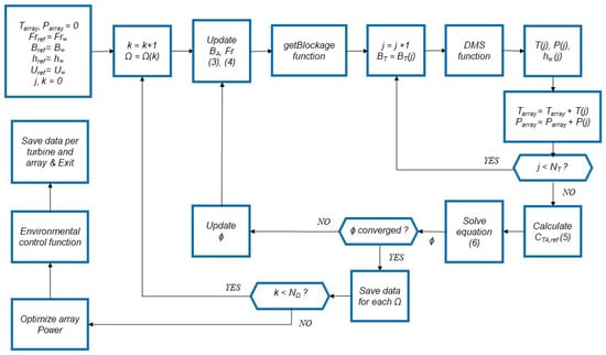
Figure 5.
Flowchart of power optimization scheme (M1) for a single array (equal rotor speed for each turbine).
If the rotor speed is allowed to vary for all turbines (Figure 6), all turbines can reach maximum performance, whilst the array power is achieved at different rotor speeds. Since this optimization scheme predicts higher mechanical power than the previous scheme, this also affects backwater depths. The chosen lateral spacing dT between the turbines influences the performance through the locally generated blockage. Hence, if activated, the environmental control function is recalled before the determination of the array thrust TA and power PA.
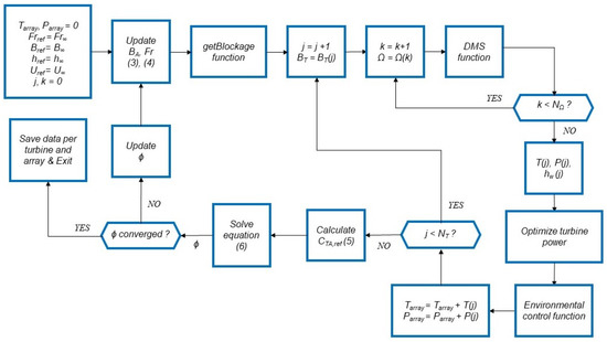
Figure 6.
Flowchart of power optimization scheme (M2) for a single array (different optimum rotor speeds for each turbine).
2.1.3. Environmental Constraint
Environmental control for over-banking risk can be an excellent aid with which to avoid significant hydraulic issues due to excessive backwater. If activated, the previous scheme is carried out once for all arrays. Thus, if one of the inflow depths is higher than the recommended value, i.e., Δhi,∞ > Δhlim, a rotor speed modifier is introduced in the code. By default, this corresponds to a reduction of 1 rpm as a first step, but it can be modified by the user. This is applied first to the most downstream array so that the code re-executes the computations for all arrays with the same rotor speed modifier. The code verifies the environmental constraint once more at the end of the procedure. If the result is negative, the code implements a new step for speed reduction, inducing a drop in the rotor performance to respect the constraint.
2.1.4. Wake Transition
The implemented methods predict the length of the far-wake distribution, with or without pre-setting. Moreover, the approximation of the free surface variation in the near-wake downstream of the turbine serves to illustrate the local effect of each rotor on the flow, as shown in Figure 7.
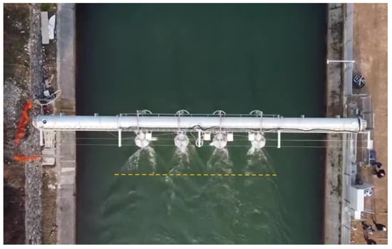
Figure 7.
Near-wake distribution of four cross-flow turbines from [3].
The flow past the turbine shows a non-uniform distribution, which is not representative of the free surface throughout the channel cross-section.
Araya et al. [23] investigated the relation between dynamic solidity σD and the transition to bluff body dynamics in a vertical-axis rotor to determine the wake recovery length. Assuming the ratio of time scales (tv/tconv), i.e., the percentage of convection time required by the blades to close the gaps in between them during rotation, and the geometric factor (RT/c), with RT denoting the turbine radius and c denoting the blade chord, the dynamic solidity is formulated in Equation (7).
ΣA represents the rotor solidity defined by Araya (Nb × c/(2πRT)), while λ is the tip speed ratio (ωRT/U0). Although both definitions are valid, σA differs from our definition of solidity, i.e., σ = Nb × c/(2RT), which is introduced later. The time scale tv represents the time required by the operating turbine to close the gaps between the blades tv = l/(NbU0λ), whilst the convective time scale is denoted as tconv, which is the time required for a free stream particle to travel the distance l = 2πRT(1 − σA), i.e., tconv = l/U0, with l denoting the sum of the gaps in the circumference of the turbine rotorIf λ >> 1, the turbine’s wake mimics that of a full cylinder with with σD ≈ 1, but if λ > 1/(2πσA), the dynamic solidity σD increases monotonically with λ or σA. If λ = 0, the degree of interaction of the incident flow with the blades is unknown as it depends on the orientation of the rotor and since σD is indeterminate; otherwise, if λ < 1/(2πσA), the dynamic solidity is negative σD < 0 with a loss of physical meaning. Based on the spectrum of the Strouhal number St vs. the downstream length (dt/DT), Araya et al. demonstrated the existence of a streamwise point where blade vortices decay to the point where they no longer account for the most energetic fluctuations in the flow so that bluff body oscillations start to dominate the wake dynamics. The far wake exhibited low-frequency oscillations typical of bluff bodies near St = 0.26, which is consistent with HAWT wake studies, e.g., those conducted by Chamorro et al. [29] and Okulov et al. [30].
σD = 1 − (RT/c) (tv/tconv) = 1 − 1/(2 π σA λ)
As a result, Equation (8) revealed a linear correlation with σD and the downstream transition location Xt where a shear-layer instability occurs, thus achieving the near-wake length in turbine diameters DT. This relation was determined by performing a linear regression between the location of the wake transitions and dynamic solidities of different vertical-axis turbines. An increasing σD gave weaker shed vortices with a faster transition into the wake.
dt = DT (4.78 − 4.93 σD)
2.1.5. Wake Recovery
A power law correlating dynamic solidity σD and the absolute minimum velocity was determined by Araya et al. [23], indicating that an increasing σD yields a faster rate or recovery of the velocity deficit into the wake, i.e., the higher the solidity, the greater the initial velocity deficit. The velocity recovery profiles of vertical-axis rotors were aligned to that of a solid cylinder according to the predictions of Schlichting [31] and Iungo and Porté-Agel [32] for turbulent free-shear flows and horizontal-axis wind turbine wakes. Since the maximum Reynolds stress was found on the spanwise plane, it is reasonable to assume that the turbine aspect ratio AR plays a significant role in the wake distribution. Indeed, an increasing aspect ratio produces more significant spanwise fluctuations in the wake recovery. The downstream recovery of the wake velocity deficit is expressed by the power law illustrated by Ouro et al. [24], which can be reversed into Equation (9) to determine the far-wake length df. In this equation, Uw represents the known streamwise velocity in the near wake, i.e., (Uw = αwU0), and a and b represent the power law coefficient and exponent according to Araya [23] for the rotor of a given aspect ratio. From the velocity deficit ΔU, one determines the local flow speed along the centerline U# = ΔU + U0. The length df is found by substituting U# with the undisturbed flow speed U∞; thus, a reduction in velocity yields ΔU = U∞ − U0.
df = DT [(ΔU/U0 + Uw)/a](1/b)
2.1.6. Including Inflow and Wake Regions
The free surface variation over and past a turbine array is modeled to consistently visualize the downstream phenomena. The depth upstream of the single-array h0 was determined via the previous iterative procedure, whilst the depth h∞ is known past the very-downstream array. The inflow region is the region where streamlines are sensitive to the rotor induction, which spans from {0} to the turbine inlet. Its length is assumed by default (d0/DT = 5.0), whereas the Standard [33] indicates (d0/DT = 2.5), according to the modeling of wind turbine inflow [34]. With 2-D modeling, Adamski [35] introduced blockage to include the bottom of a channel for an unbounded rotor. Plots of the dynamic pressure demonstrated that the wake persists further downstream for turbines at the free surface proximity, and the wake expands more uniformly for deeper installation. The minimum wake velocity at the turbine centerline at 20 DT downstream diminished for placement close to the free surface. Adamski demonstrated the enhancement of free surface fluctuations with turbine placement near the free surface, with stationary waves generated downstream and with amplitude decaying in space.
The near-wake region past the turbine is characterized by shed vortices creating a shear layer isolating the low-momentum region of the core flow from the high-velocity region outside of the wake. The transition point is defined as the streamwise coordinate where bluff body oscillations start to dominate the wake dynamics. In the near-wake region, blade vortices decay until they no longer account for high energy fluctuations. According to Ouro et al. [24] and Müller et al. [36], the near-wake region is exhausted within two turbine diameters past the turbine (dw/DT ≤ 2), as drawn approximately with a dashed line in Figure 7.
Within the transition region (2 ≤ dw/Dt ≤ 5), the wake starts to vertically and laterally expand with a larger ambient turbulent flow entrainment that increases the turbulent fluxes and intensity, and momentum starts to recover faster [24]. In the far-wake region, the core momentum is recovered according to turbine dynamic solidity and aspect ratio such that Reynolds stresses decay to their minimum at (df/DT = 14) and (df/DT = 10), respectively. The code automatically determines a near-wake length according to Araya’s procedure once dynamic solidity σD (7) has been derived.
Since the lowest momentum corresponds to the minimum depth past the turbine hw, the free surface deformation over the rotor from downstream hw to upstream h0 can be drawn by a cosine wave of a half amplitude, whose wavelength results in twice the sum (d0 + dw). The depth hw past each turbine is approximated from Equation (10) according to Whelan et al. [37], wherein αw denotes the wake interference factor from free surface actuator disc polynomial and where the effective turbine drag coefficient CD is known iteratively from the DMS code.
hw/h0 = 1 − Fr2/2(CD + αw2 − 1)
Thus, the inflow length dd0 is added to the lengths of the near-wake region dw, transition region dt, and far-wake region df. However, to account for uncertainty due to the mutual disturbance of multi-turbine wakes that carry turbulence further downstream, a correction factor is introduced. This factor has the same function of including an array-scale wake size as illustrated by Nishino and Willden for tidal applications [12]. Since a semi-empirical relation for the recovery length due to the superposition of multi-turbine wakes has not yet been standardized in the literature, a user-dependent parameter was introduced to enhance the far-wake length. A default value of fc = 1.1 is assigned in this work. The transition region’s wake length is also dependent on another default parameter that was set (dt/DT = 3.0) according to the research of Müller et al. [36]. The above procedure is valid for the very-downstream array. The assessment of the additional turbine arrays is described in the multi-array scheme paragraph.
2.1.7. Backwater Region
Since channel geometry, Manning’s coefficient n, bed slope S, and inflow depth h0 are known, a direct step method is developed at this juncture to determine the backwater distribution of the gradually varied flow. This can be performed according to the energy or momentum principle according to Henderson [22]. At each step, the former reduces the water depth slightly from the previous value of a discrete dy so that the new wetted area A, the hydraulic radius Rh, and mean flow speed U can be calculated. Since the Chezy coefficient C is given by the ratio (Rh1/6/n) and the local friction slope Sf is inversely proportional to the square of C according to Manning’s formula, Sf is simply derived from (11). Once the mean values SJ,avg, and Fravg are determined from two steps, the discrete longitudinal specific energy variation (dE/dx)avg is derived from the 1-D Saint-Venant Equation (12). The amount (dE/dx)avg divided by dE (13) yields the distance dx, and the coordinates x and h are collected from the inflow depth h0 to the far-field h∞.
Sf = U2n2/Rh4/3
dE/dx = S − Sf,avg
dE = dy (1 − Fravg2)
The second method is based on the local momentum (14), with denoting the moment of area of the cross-section, and denoting the depth from the surface to the section centroid, according to Henderson [22]. The average shear stress over a step τavg is computed as a function of the friction slope from (15), whilst the longitudinal steps dx are found by averaging the discrete momentum variation dM to the mean step longitudinal area, as shown in (16), with p denoting the wetted perimeter.
τavg = ρg Rh Sf,avg
dx = dM/(A S − p τavg/(ρg))
2.2. Multi-Array Scheme
The macroscopic functional scheme is fully depicted in Figure 8. After the initialization of the parameters for the first array, the optimization tool of Figure 5 or Figure 6 selects cycles to perform by determining the optimum rotor speed that maximizes the array power for each row from 1 to NA, with or without the environmental control. After the estimation of the wake recovery length dW, the first array is placed at the longitudinal coordinate Xarray(1) = Xref + dW, thus establishing the initial downstream coordinate Xref. In our case, Xref = 0, whilst dW yields the distance from the determined zero to the first array’s installation. The latter array is placed at a distance dA from the former. By making use of the backwater estimate, depths and flow velocities are determined for the channel at each discrete step up to recovery.
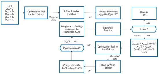
Figure 8.
Flowchart for solving DMS applied to an array of HK turbines.
If the new array’s position anticipates the depletion of the previous backwater, an interpolation at the new Xref(2) yields the reference parameters, i.e., Frref, Bref, Uref, and href. After setting Xref(i) = Xarray(i), the code iterates the optimization tool and the wake function to allow a new Xref to be found at convergence. Indeed, this represents the first estimation, as the wake must develop entirely such that Xref(i) = Xarray(i) − dW. This implies that Xref for the second array is achieved at a gradually varied station immersed in the backwater. At the reference position, the depth from the still water level to the top of the turbines is again determined, allowing the free surface LMADT equations of the turbine model to account for the actual installation depth, which are further updated during the array’s iteration.
Two examples of three and four arrays, deployed with different longitudinal spacings before the decay of the backwater, are illustrated in Figure 9, showing the free surface variation immediately downstream.
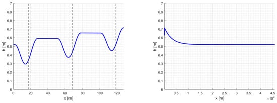
Figure 9.
(Left) Example of free surface variation based on three turbine arrays of four 6 m2 turbines vs. distance with array spacing of 50 m. The local free surface variation past the turbines is visualized for the central rotors. (Right) Effect of the asymptotic backwater past the three turbine arrays.
The image on the left shows that the visualization of the water depth drop is based on the central turbine for each array, but it can be modified according to the user. Backwater is present upstream of each array, although it just slightly noticeable. The image on the right displays the decay of the backwater from the most upstream array up to its complete decay.
If the new array position is placed far upstream beyond the decay of the backwater, equal power is extracted due to identical fluid-dynamic conditions [2] because the channel is idealized as an equally distributed geometry towards infinity, with constant bed slope and roughness and no other hydraulic transitions or obstacles. As a result, equal free surface variation and axial thrust force are expected. However, depending on the slope and Manning’s roughness coefficient, this is likely to occur with extreme spacings between the arrays.
2.3. Optimum Design Solution
The power of the plant consists of the sum of the power contributions from all arrays. In turn, the array power consists of the sum of the power outputs from all the turbines.
Considering turbines with equal geometry and size for all arrays, and replacing the summation of the power coefficients with a function F, P can be written as
Therefore, the optimization consists of finding the power coefficients that maximize the objective function P, with conditions of backwater limitation Δh applied, thus maximizing the investment’s net present value (or minimizing the Levelized Cost of Energy LCoE). LCoE is used to assess and compare different methods of energy production and consists of the ratio of the net present value of the total costs to the net present value of the electrical energy produced over a plant’s lifetime. The design solution that maximizes F with all the constraints is given by
Pmax = [1/2ρATU∞ × max(F), min(Δh), min(LCoE)]
Other conditions can be added, e.g., the minimization of sound emission, the minimization of structural loads to limit the impact of structural works on canal embankments, etc. However, the focus of this work is on power and backwater, and the additional assessments will be presented in another publication.
3. Results and Discussion
The momentum method was tested to investigate the effect of turbine spacing and array spacing on axial forces and power, which indicated an increase in thrust reasonably proportional to the rise in backwater depth. The predictions were carried out based on the concession discharge of the hydropower canal depicted in Figure 2, which was subject to ongoing hydrokinetic turbine testing.
An optimization procedure was thus conducted on some design cases based on different array features. Array blockage and turbine solidity were kept constant to assess the most suitable design solutions, and the turbine aspect ratio was allowed to vary between alternatives to meet the requirements of the fixed array blockage ratio.
A final computation is performed based on the research shown in [38] to predict the distribution of the free surface variation and maximum power output for a large plant incorporating many arrays.
3.1. Sensitivity Analysis
Predictions of the array thrust force and power are collected vs. the global inflow factor ϕg—defined as Ui/U∞, with the subscript (i) related to the actual array—starting from downstream. The same three-bladed geometry of the prototype [37] is used for the simulations, but lower solidity and a higher aspect ratio are chosen to reduce fatigue and torque ripple. In this work, solidity is defined as the chord-to-diameter ratio multiplied by the number of blades, i.e., σ = Nb × c/(2RT). For the first assessment, a rotor size (DT × HT) of 2.0 × 3.0 m is selected, with a shaft diameter D0 of 0.18 m, solidity σ = 0.36, and aspect ratio (AR) of 1.5. The blade profile is an asymmetric DU06W200, which is less prone to dynamic stall at low tip speed ratios, with a chord length c of 0.24 m. Since the computational time increases with the number of arrays, faster simulation is facilitated with an azimuthal displacement of 15 deg, whilst the starting turbine depth is 0.2 m from the still water level. The streamtube expansion is not activated to limit the computational cost of the simulation. For the same reason, no environmental constraint is switched on for the initial predictions. The sensitivity of array thrust and power based on turbine spacing dT and array spacing dA is investigated in the following sections.
3.1.1. Turbine Spacing (dT)
The array thrust coefficient CTA,∞ vs. global inflow factor ϕg for a plant of four arrays is shown on the left side of Figure 10 according to different turbine spacings dT (different colors). Each marker represents the array CTA,∞ from the most upstream array (left side) to downstream (right side).
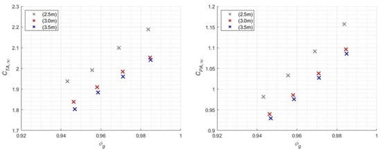
Figure 10.
(Left) Effect of the turbine spacing dT on the array thrust coefficient CTA,∞ vs. global inflow factor ϕg for a plant of four arrays. (Right) Effect of the turbine spacing dT on the array power coefficient CPA,∞ vs. global inflow factor ϕg for a plant of four arrays. The three series of arrays from downstream to upstream are depicted with the same color from the right to left.
Spacings of 2.5 m, 3.0 m, and 3.5 m between each rotor vertical-axis (corresponding to 1¼, 1½, and 1¾ equivalent lengths based on turbine diameters DT) are chosen and the array spacing dA is set to 50 m. The lower turbine spacing of 2.5 m guarantees a safety margin of 0.5 m between the blades of neighboring turbines, while the higher spacing of 3.5 m represents the limit for four turbines (2.0 × 3.0 m in size) in relation to the available wetted area and the selected clearance between the top of the turbine and the still water level as if ideally deployed in the undisturbed flow. On the right side of Figure 10, the array power coefficient CPA,∞ is investigated. CTA,∞ and CPA,∞ are calculated as TA,i/(½ρAarrayU∞2) and PA,i/(½ρAarrayU∞3), respectively.
Both array thrust and power drop as the turbine spacing dT increases; however, for a single simulation of four arrays and proceeding upstream (from right to the left), the array power decreases linearly. The first step in dT of 0.5 m (from 2.5 to 3.0 m) implies the highest drop in CTA,∞ and CPA,∞, while a second step induces a smaller difference. Since the turbine spacing dT defines each flow passage and the turbine blockage ratio BT,j, the higher the dT, the smaller the blockage for the core turbines, which is usually expected to convert more power in the array. Therefore, a reduction in thrust force and power is expected as dT increases. Maximum thrust and power are achieved by the very-downstream array depicted on the right. At each hydraulic transition, mechanical power and total thrust force drop with the reduction in the inflow factor ϕg.
Linearity is demonstrated for the variations in power with a very high correlation (R2 > 0.99) for all simulations. Moreover, linearity holds only for a small plant. As better illustrated in the “Large plants” paragraph, once the scale of the plant is expanded, the behavior is no longer linear.
3.1.2. Array Spacing (dA)
When dT is fixed, thrust and power sensitivity vs. global inflow factor ϕg is tested by varying the array spacing dA from 50 m to 500 m, as illustrated in Figure 11. Since the rotor shape and turbine spacing dT are the same in these predictions, the first array downstream shares the same outputs regardless of dA. Array thrust and power output increase slightly from array to array as dA increases because the backwater reduces progressively with distance, thus determining a higher recovery of the water velocity.
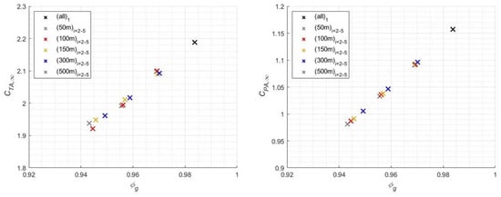
Figure 11.
(Left) Effect of the array spacing dA on the array thrust coefficient CTA,∞ vs. global inflow factor ϕg for a plant of four arrays. (Right) Effect of the array spacing dA on the array power coefficient CPA,∞ vs. global inflow factor ϕg for a plant of four arrays. The most downstream array is indicated with a black marker. The series of arrays from downstream to upstream are depicted with the same color from right to left.
Hence, a greater amount of energy can be harnessed at the farthest array if dA is high. This concept extends to an ideal condition. If the spacing between two arrays exceeds the recovery length of the backwater, the power converted from both is the same. This proves the physical consistency of the model. Hence, from the perspective of pure energy conversion, the best choice would be to ensure that they are place far apart, thus affording as much energy as possible and reducing, albeit partially, the risk of upstream flooding.
Again, CTA,∞ and CPA,∞ reduce progressively at the upstream arrays, suggesting that the upstream rotors are optimized at a lower rotor speed than that of the downstream rotors. In the image, the CPA,∞ from the same plant is linearly distributed over a straight line regardless of array spacing and number. Hence, for a small-scale plant, linearity is again demonstrated with R2 > 0.99. However, the deviation in CTA,∞ and CPA,∞ at the second array between all feasible dA is not large, and it becomes more consistent from the third array onward.
3.2. Array Design
The previous sensitivity analysis demonstrates the improvement in the array power output with a reduced turbine spacing, even though higher axial forces and depths are afforded. Another finding is that highly spaced arrays harness more energy than closer arrays. However, the choice of the array spacing is based on the available length of the channel stretch and the expected investment, and this implies knowledge of the number of arrays. It is expected that a cash flow assessment of the best predictions will be incorporated in future works to achieve the most convenient design solution.
In the ideal scenario considered herein, 1 km of the canal is dedicated to simulations with four turbine arrays, with the target of maintaining a swept area of 24 m2, thus generating a constant blockage ratio (BA,∞) of 0.279 based on Equation (1). Turbines are scaled according to Table 1, assuming a fixed turbine solidity, thus excluding the dependency of CP,∞ on σ. However, the turbine spacing dT cannot be fixed due to the different turbine sizes within a limited canal cross-section. Hence, although BA,∞ and σ are constant, this does not hold for dT, whose variations slightly affect hydrodynamic forces. Notice that the turbine spacing dT is chosen to be as small as possible to increase the turbine blockage and maximize array power extraction. Again, a minimum breadth of 0.5 m is left as a safety margin for all predictions.

Table 1.
Cases investigated with respect to array design. Nomenclature: NA number of arrays, NT number of turbines per array, dA array spacing, dT turbine spacing, AT turbine swept area, AR turbine aspect ratio, DT turbine diameter, HT turbine height, and c blade chord.
By fixing the height of the turbines to 3.0 m and maintaining a level of solidity of σ = 0.36, the diameter is determined from the ratio AT/HT. Moreover, the chord is scaled according to the above definition of σ, yielding c = 0.24 × RT. The investigation is performed with arrays consisting of two larger turbines with an AR of 0.75, three turbines with an AR of 1.125, and four smaller turbines with an AR of 1.5. The longitudinal spacing is fixed, i.e., dA = 250 m. The array power coefficients CPA,∞ and free surface variation Δhi,∞ distributed over the arrays for each turbine aspect ratio are outlined in Figure 12.
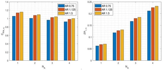
Figure 12.
(Left) Array power coefficient CPA,∞ vs. number of arrays NA. (right) Free surface variation Δhi,∞ vs. number of arrays NA. Different colors indicate the various simulations (blue markers indicate 2-turbine arrays with AR = 0.75, red markers indicate 3-turbine arrays with AR = 1.125, and yellow markers indicate 4-turbine arrays with AR = 1.5).
The prediction demonstrates that a higher CPA,∞ is achieved by four closely spaced turbines with an AR = 1.5. Although CPA,∞ does not vary noticeably between cases (b) and (c), the highest array performance is achieved by a row of four closely spaced turbines with an AR = 1.5, while a poor result is determined for a row of two larger turbines (AR = 0.75). According to the results of Section 3.1, the array power output decreases from the most downstream array toward the upstream direction. The limitation of higher power conversion is represented by the increased free surface variation Δhi,∞ determined with respect to the undisturbed flow depth, i.e., (hi − h∞).
The outputs of the optimum solution of this assessment are shown in Figure 13 from the most downstream array (#1) to the most upstream (#4) array. The schemes on the left column represent the local free surface distribution generated by each turbine over its predicted longitudinal extension. The direction of the flow is from right (inflow) to left (flowing past the area of turbulent dissipation). Since the turbines deployed at the center of the canal convert more power, they generate higher free surface variation, whilst a mild variation occurs for the lateral turbines. The flow past array (#1) represents the undisturbed flow achieved downstream of the hydrokinetic plant.
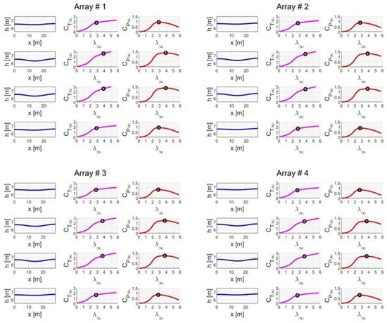
Figure 13.
Optimum design: 4 arrays of 4 turbines with AR = 1.5 operating at λ∞,opt. The left column indicates the local free surface deformation in space for each turbine with flow directed from right to left. The central and last columns represent turbine thrust coefficient CT,∞ and power coefficient CP,∞, respectively, for each turbine of the array.
The central and right schemes represent the thrust coefficient CT,∞ and power coefficient CP,∞ curves, respectively, vs. the tip speed ratio λ∞. Although not evident in these images, the depth in the canal increases from the first to the last array, and the curves of CT,∞ and CP,∞ slightly drop from downstream to upstream. The inflow speed of the arrays placed furthest upstream drops, and this reduces, albeit partially, the performance of the upstream rotors. Notice that the lateral turbines and core turbines are equal when aligned two by two, and thus show equal power coefficients. This is a drawback of the momentum model, which is incapable of catching differences between inward or outward rotation directions.
By activating the environmental constraint to limit the backwater to a value of Δhlim based on specific regulations or channel manager decisions, one may predict different power outputs from each array. If Δhlim is smaller than the expected hydrostatic head variation generated by a certain array of turbines operating at maximum power, a sub-optimal response induced by the rotor speed limitation would be achieved. This would mean a lower power output from the turbines drawn for higher mechanical power, thus limiting the choice of the best array design solution between lower-capacity plants.
3.3. Large Plants
Measurements of the drag forces were carried out at the DICAM Unitn Hydraulic Laboratory with plates (hp 54 mm × wp 280 mm) built from a porous metallic frame deployed to occupy the rectangular channel span (wc = 305 mm) almost entirely. Depth and Froude numbers were allowed to vary according to a subcritical hydraulic regime (Fr < 1) by adjusting the level of downstream drain and thus automatically modifying the blockage ratio.
The images in Figure 14 were obtained by placing two of the perforated plates at a constant spacing and fixed elevation from the channel bed. Notice that the flow is directed from right to left. Considering the limited channel length available in the facility, other plates were allowed to be “added” upstream of the last plate only by repeating the test with a new regulation of the downstream flow through the drain. The previous backwater was recreated downstream for a new test, for which there were no changes in the spacing between the plates. Depths were accurately measured at a precise spacing from the upstream plate to allow for reliable matching with the new regulated depths.

Figure 14.
(Left) Discharge Qc = 32.3 l/s, spacing between the plates d = 0.316 m, height from the bottom yz = 0.115 m, upstream depth h0 = 0.20 m, upstream flow speed U0 = 0.530 m/s, and measured thrust force over the first plate = 7.51 N. (Right) Discharge Qc = 35.7 l/s, spacing between the plates d = 1.0 m, height from the bottom yz = 0.101 m, upstream depth h0 = 0.201 m, upstream flow speed U0 = 0.583 m/s, and measured thrust force over the first plate = 5.54 N.
The aforementioned phenomenon occurs if one approximates the channel as an ideal water body free of obstacles, whose geometric cross-section is uniformly distributed over the length of interest, and with a constant elevation of the plate from the channel bottom. Hence, the steady distribution of depth, flow speed, thrust, and power may be predicted over a certain distance to improve the modeling of combined hydroelectric–hydrokinetic systems.
Since the turbines are expected to operate at maximum performance, the resultant backwater depth is not as severe as that generated at higher rotor speeds. The highest turbine thrust force occurs at a rotor speed at which almost no mechanical power is collected at the shaft and the energy dissipation in the channel flow is maximum. To render a test more consistent with real turbines, the porosity of the plates should be adjusted progressively upstream to approximate the regulation of the optimum turbine tip speed ratio λ∞,opt.
According to the measurements of the drag forces and depth of each plate, an asymptotic trend of the deviation in the inflow depth was speculated for a high number of arrays of optimized turbines.
Figure 15 shows the expected reduction in the water depth variation at the ith array, even though bed slope and exact free surface deformation are neglected in the image. As mentioned, the turbine elevation zd is fixed from the canal bed, with the submergence depth increasing with each successive array. In contrast, if the turbine depth is maintained constant at the free surface proximity, higher depths would be expected upstream.

Figure 15.
The asymptotic trend of water depth variation Δh caused by increasing the number of arrays or turbines. Although not appreciable, backwater depth decreases upstream from each hydraulic transition. (Image is not to scale).
Therefore, a progressive drop in flow speed upstream is inevitable unless the new row is placed after the backwater exhaustion, even when many kilometers away.
A single-turbine test was carried out to most accurately visualize this phenomenon and reduce the inaccuracy resulting from the numerical procedure. For this purpose, a prediction is made wherein a series of equal turbines of the type shown in [38] are positioned with an array spacing of 10 m in the canal illustrated in the same work.
The water depth increases after each hydraulic transition, and the total head variation ΔHi reduces the mechanical power availability. The array (or turbine) power output PA scales linearly for a small number of arrays (≤5); then, it is approximated by a quadratic polynomial to about 20–25 arrays (which is still reasonable for large plants). For an extremely large number of arrays, a logarithmic curve fits the data, with R2 > 0.99.
For the case investigated, the deviation in the inflow depth Δ(hi − hi−1) is approximated with a power law y = a × xb, in which x denotes the number of arrays, the coefficient a > 0, and the exponent b < 0. Ideally, Δ(hi − hi−1) would drop to zero asymptotically, suggesting a constant inflow depth for a large number of arrays. However, this can be approximated as the deviation in water depth Δ(hi − hi−1) approaches the numerical accuracy of the model (i.e., 1 mm) in Figure 16, implying that the inflow hydrostatic head is expected to remain constant after a certain number of arrays within the imposed physical tolerance. Moreover, a slight drop in depth between two arrays is still present due to the backwater. This trend can be generalized for any array layout of aligned turbines.
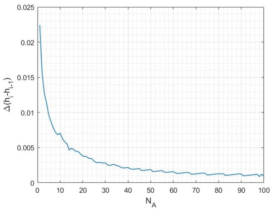
Figure 16.
Deviation in inflow depth Δ(hi − hi−1) vs. the number of arrays NA.
Therefore, the imposed physical tolerance to the model determines the length scale to ascertain the asymptotic deviation Δ(hi − hi−1). If a tolerance of 5 mm was allowed (which is more consistent with the typical sensitivity level of many probes), an asymptotic deviation would be reached after about 15 arrays (in this example). Thus, the expected far-field condition in a large plant of aligned rotors more closely resembles Figure 15, even though this distribution is valid for ideal canals.
The assumptions of an infinitely long channel with a homogeneous, unobstructed geometry and stationary flow do not realistically represent the characteristics of large plants. Indeed, a transient variation in the flow rate would imply that the discharge cannot be assumed to be constant over the entire stretch of a channel at the same time. Turbulence, local head losses, and finite lengths of artificial canals further complicate the real flow distribution.
A similar problem was illustrated by Karteznikova and Ravens [39] with respect to a homogeneous distribution of closely spaced turbines in a regular channel. The authors modeled an almost flat free surface far upstream, speculating that a uniform flow with a change in Manning’s roughness coefficient had been achieved, even though a non-realistic power extraction scheme based on Garrett and Cummins’ equation [40] was included.
4. Conclusions
The presented multi-array tool yields a valuable assessment of turbine arrays along mild slope hydropower canals and can be used to estimate a reliable power output with systematic modeling of each hydraulic transition. The main contributions of this quantitative tool are as follows:
- The exploitable capacity in a channel flow can be estimated with turbines operating at maximum performance and considering canals and rotors’ geometry, turbine spacing, and array spacing.
- The tool incorporates an environmental assessment of a canal, providing visualizations of a 1-D free surface distribution showing the backwater propagating from each successive array from a downstream cross-section.
- By integrating a Double Multiple Streamtube model operating in a confined environment with a variable Froude number and blockage ratio, the tool overcomes the limitations encountered in ideal analytical modeling with actuator discs. Indeed, the model accounts for the turbine’s fluid dynamic losses, turbulent mixing loss, and channel friction losses to calculate upstream free surface propagation.
The simulation outputs based on the cases investigated in this paper show the following results:
- A sensitivity analysis demonstrated that closely spaced turbines in aligned arrays convert more power than widely spaced turbines. Indeed, an increase in turbine spacing shrinks the size of each flow passage and enhances the level of turbine blockage. As confirmed by the predictions, higher turbine blockage is achieved by the rotors deployed at the center of the row, which notoriously, harness more energy.
- If the hydrokinetic plant design involves a canal stretch of a given length, the sensitivity analysis shows that closely spaced arrays perform inadequately in subcritical flows. Wide array spacing allows for the partial recovery of superior flow conditions for the new array, thus implying higher power output.
- Assuming a scheduled number of rows with an equal number of turbines of a given solidity, the comparison of different array layouts for the investigated canal cross-section demonstrates that four small turbines of a high aspect ratio are more beneficial than three medium-size turbines or two large turbines of a small aspect ratio. While constraining the maximum expected free surface variation in the plant, a sub-optimal response induced by the rotor speed limitation may be achieved by the same array designed for higher capacity.
- For a small plant (number of arrays ≤ 5), a row’s maximum power output drops linearly with respect to the number of arrays, whereas for a reasonable number of arrays in a large plant, this measure can be approximated by a quadratic polynomial.
- Since the deviation in the inflow depth ideally tends to be zero for a large multi-array plant, the backwater depth far upstream is speculated to remain constant at each inflow station, even though a reduction in depth within each array spacing is recurrent.
With this tool, an assessment of the capacity enabled by multiple arrays was performed. Future developments will be directed toward the temporal analysis of flow rates via duration curves developed for each channel for which temporal data are known. Therefore, the tool will be timed to calculate new performance curves for the turbines and estimate the annual energy production (AEP) of a plant, as well as a possible computation of its capacity factor.
Author Contributions
Conceptualization, L.C. and L.B.; methodology, L.C.; software, L.C.; validation, L.C.; formal analysis, L.C., L.B. and S.D.; investigation, L.C.; resources, L.C. and L.B.; data curation, S.D.; writing—original draft preparation, L.C.; writing—review and editing, L.C., L.B. and S.D.; visualization, L.C.; supervision, L.B.; project administration, L.B. All authors have read and agreed to the published version of the manuscript.
Funding
This research received no external funding.
Data Availability Statement
Not applicable.
Conflicts of Interest
The authors declare no conflict of interest.
Nomenclature
| A | Cross-section area, m2 |
| AF | Turbine flow-passage area, m2 |
| AT | Turbine swept area, m2 |
| AR | Turbine aspect ratio |
| Moment area, m2 | |
| BA | Array blockage ratio, NTAT/A |
| BT | Turbine blockage ratio, AT/AF |
| CP,∞ | Turbine power coefficient, P/(½ρAU∞3) |
| CPA,∞ | Array power coefficient, PA/(½ρArrayU∞3) |
| CT,∞ | Turbine thrust coefficient, T/(½ρAU∞2) |
| CTA,∞ | Array thrust coefficient, TA/(½ρArrayU∞2) |
| c | Blade chord, m |
| Dh | Hydraulic depth, A/w |
| D0 | Shaft diameter, m |
| DT | Turbine diameter, m |
| d | Wake length, m (see subscripts) |
| dA | Array spacing, m |
| dT | Turbine spacing, m |
| dE | Specific energy variation, m |
| dW | Total wake length, m |
| dx | Discrete longitudinal step, m |
| dy | Discrete variation in water depth, m |
| Fr | Froude number, U/(gDh)½ |
| g | Gravity acceleration, m/s2 |
| HT | Turbine height, m |
| h | Water depth, m |
| M | Channel momentum, m2 |
| NA | Number of arrays |
| NT | Number of turbines |
| NΩ | Number of selected rotor speeds |
| n | Manning’s coefficient, m−1/3s |
| P | Turbine power, W |
| PA | Array power, W |
| Qc | Channel discharge, m3/s |
| Rh | Hydraulic radius, m |
| RT | Turbine radius, m |
| S | Bed slope, m/m |
| Sf | Friction slope, m/m |
| T | Axial thrust force, N |
| TA | Array axial thrust force, N |
| U | Mean flow speed, m/s |
| w | Free surface width, m |
| X | Axial coordinate from the origin, m |
| ΔH | Total head variation, m |
| Δh | Free surface variation, m |
| Δ(hi − hi−1) | Deviation in water depth, m |
| Δhlim | Environmental constraint, m |
| ΔU | Flow speed variation, m/s |
| Ω | Rotor speed, rpm |
| αw | Near-wake interference factor, U/U0 |
| λ | Tip speed ratio, ωRT/U |
| ρ | Fluid density kg/m3 |
| σ | Rotor solidity, Nb c/(2RT) |
| σA | Rotor solidity from [23], Nb c/(2πRT) |
| σD | Dynamic solidity, 1 − 1/(2πσAλ) |
| ϕ | Inflow factor, U0/Uref |
| ϕg | Global inflow factor, U0/U∞ |
| ω | Angular velocity rad/s |
| Subscripts | |
| array | Array position |
| f | Far-wake |
| opt | Optimum |
| ref | Reference |
| t | Transition-wake |
| w | Near-wake |
| Short forms | |
| DMS | Double Multiple Streamtube |
| HK | Hydrokinetic |
| LMADT | Linear Momentum Actuator Disc Theory |
References
- Liu, Y.; Packey, D.J. Combined-Cycle Hydropower Systems-The Potential of Applying Hydrokinetic Turbines in the Tailwaters of Existing Conventional Hydropower Stations. Renew. Energy 2014, 66, 228–231. [Google Scholar] [CrossRef]
- Cacciali, L.; Battisti, L.; Dell’Anna, S. Backwater Assessment for the Energy Conversion Through Hydrokinetic Turbines in Subcritical Prismatic Canals. Ocean Eng. 2023, 267, 113246. [Google Scholar] [CrossRef]
- Available online: https://www.he-powergreen.it/ (accessed on 15 December 2022).
- Gauvin-Tremblay, O.; Dumas, G. Hydrokinetic Turbine Array Analysis and Optimization Integrating Blockage Effects and Turbine-Wake Interactions. Renew. Energy 2022, 181, 851–869. [Google Scholar] [CrossRef]
- Gonzalez-Gorbena, E.; Qassim, R.Y.; Rosman, P.C.C. Optimisation of Hydrokinetic Turbine Array Layouts via Surrogate Modelling. Renew. Energy 2016, 93, 45–57. [Google Scholar] [CrossRef]
- Okulov, V.L.; Naumov, I.V.; Kabardin, I.K.; Litvinov, I.V.; Markovich, D.M.; Mikkelsen, R.F.; Sørensen, J.N.; Alekseenko, S.V.; Wood, D.H. Experiments on Line Arrays of Horizontal-Axis Hydroturbines. Renew. Energy 2021, 163, 15–21. [Google Scholar] [CrossRef]
- Septyaningrum, E.; Hantoro, H.; Utama, I.K.A.P.; Prananda, J.; Nugroho, G.; Mahmashani, H.; Satwika, N.A. Performance Analysis of Multi-Row Vertical Axis Hydrokinetic Turbine-Straight Blade Cascaded (VAHT-SBC) Turbines Array. J. Mech. Eng. Sci. 2019, 13, 5665–5688. [Google Scholar] [CrossRef]
- Riglin, J.; Daskiran, C.; Jonas, J.; Schleicher, W.C.; Oztekin, A. Hydrokinetic Turbine Array Characteristics for River Applications and Spatially Restricted Flows. Renew. Energy 2016, 97, 274–283. [Google Scholar] [CrossRef]
- Vennell, R.; Draper, S.; Funke, S. Designing Large Arrays of Tidal Turbines: A Synthesis and Review. Renew Sustain. Energy Rev. 2015, 41, 454–472. [Google Scholar] [CrossRef]
- Cacciali, L.; Battisti, L.; Dell’Anna, S. Free Surface Double Actuator Disc Theory and Double Multiple Streamtube Model for In-Stream Darrieus Hydrokinetic Turbines. Ocean Eng. 2022, 260, 112017. [Google Scholar] [CrossRef]
- Nishino, T.; Willden, R.H.J. The Efficiency of an Array of Tidal Turbines Partially Blocking a Wide Channel. J. Fluid Mech. 2012, 708, 596–606. [Google Scholar] [CrossRef]
- Nishino, T.; Willden, R.H.J. Two-Scale Dynamics of Flow Past a Partial Cross-Stream Array of Tidal Turbines. J. Fluid Mech. 2013, 730, 220–244. [Google Scholar] [CrossRef]
- Draper, S.; Nishino, T. Centred and Staggered Arrangements of Tidal Turbines. J. Fluid Mech. 2014, 739, 72–93. [Google Scholar] [CrossRef]
- Vogel, C.R.; Houlsby, G.T.; Willden, R.H.J. Effect of Free Surface Deformation on the Extractable Power of a Finite Width Turbine Array. Renew. Energy 2016, 88, 317–324. [Google Scholar]
- Gauvin-Tremblay, O.; Dumas, G. Two-Way Interaction Between River and Deployed Cross-Flow Hydrokinetic Turbines. J. Renew. Sustain. Energy 2020, 12, 034501. [Google Scholar] [CrossRef]
- Myers, L.; Bahaj, J. Wake Studies of a 1/30th Scale Horizontal Axis Marine Current Turbine. Ocean Eng. 2007, 34, 758–762. [Google Scholar] [CrossRef]
- Filizola, N.; Melo, E.; Armijos, E.; McGlynn, J. Preliminary Analysis of Potential for River Hydrokinetic Energy Technologies in the Amazon River; IDB Technical Note (Energy Division), IDB-TN-891; Inter-American Development Bank: Manaus, Brazil, 2015. [Google Scholar]
- Jacobson, J.P. Assessment and Mapping of the Riverine Hydrokinetic Resource in the Continental United States (No. 1026880); Electric Power Research Institute (EPRI): Washington, DC, USA, 2012. [Google Scholar]
- Ridgill, M.; Neill, S.P.; Lewis, M.J.; Robins, P.E.; Patil, S.D. Global Riverine Theoretical Hydrokinetic Resource Assessment. Renew. Energy 2021, 174, 654–665. [Google Scholar] [CrossRef]
- D’Auteuil, S.; Birjandi, A.; Bibeau, E.; Jordan, S.; Soviak, J.; Friesen, D. Riverine Hydrokinetic Resource Assessment Using Low Cost Winter Imagery. Renew. Sustain. Energy Rev. 2019, 105, 293–300. [Google Scholar] [CrossRef]
- Botto, A.; Claps, P.; Ganora, D.; Laio, F. Regional-Scale Assessment of Energy Potential from Hydrokinetic Turbines Used in Irrigation Channels. In Proceedings of the SEEP2010 Conference Proceedings, Bari, Italy, 29th June – 2nd July2010. [Google Scholar]
- Henderson, F.M. Open Channel Flow; MacMillan Company: New York, NY, USA, 1966. [Google Scholar]
- Araya, D.; Colonius, T.; Dabiri, J.O. Transition to Bluff-Body Dynamics in the Wake of Vertical-Axis Wind Turbines. J. Fluid Mech. 2017, 813, 346–381. [Google Scholar] [CrossRef]
- Ouro, P.; Runge, S.; Luo, Q.; Stoesser, T. Three-Dimensionality of the Wake Recovery Behind a Vertical Axis Turbine. Renew. Energy 2019, 133, 1066–1077. [Google Scholar] [CrossRef]
- Malini, C. Il Canale Biffis. Serie Acque e Bonifiche; Sometti Editoriale: Mantova, Italy, 2017; ISBN 8874956762. [Google Scholar]
- Chiu, C.L. Entropy and Probability Concepts in Hydraulics. J. Hydraul. Eng. 1987, 113, 583–599. [Google Scholar] [CrossRef]
- Moramarco, T.; Singh, V.P. Formulation of the Entropy Parameter Based on Hydraulic and Geometric Characteristics of River Cross Sections. J. Hydrol. Eng. 2010, 15, 852–858. [Google Scholar] [CrossRef]
- Farina, G.; Alvisi, S.; Franchini, M.; Moramarco, T. Three Methods for Estimating the Entropy Parameter M Based on a Decreasing Number of Velocity Measurements in a River Cross-section. Entropy 2014, 16, 2512–2529. [Google Scholar] [CrossRef]
- Chamorro, L.P.; Hill, C.; Morton, S.; Ellis, C.; Arndt, R.E.A.; Sotiropoulos, F. On the Interaction Between a Turbulent Open Channel Flow and an Axial-Flow Turbine. J. Fluid Mech. 2013, 716, 658–670. [Google Scholar] [CrossRef]
- Okulov, V.L.; Naumov, I.V.; Mikkelsen, R.F.; Kabardin, I.K.; Sørensen, J.N. A Regular Strouhal Number for Large-Scale Instability in the Far Wake of a Rotor. J. Fluid Mech. 2014, 747, 369–380. [Google Scholar] [CrossRef]
- Schlichting, H. Boundary Layer Theory, 4th ed.; McGraw-Hill: New York, NY, USA, 1960. [Google Scholar]
- Iungo, G.V.; Porté-Agel, F. Volumetric Lidar Scanning of Wind Turbine Wakes Under Convective and Neutral Atmospheric Stability Regimes. J. Atmos. Ocean. Technol. 2014, 31, 2035–2048. [Google Scholar] [CrossRef]
- International Standard IEC. IEC 61400-12; Power Performance Measurements of Electricity Producing Wind Turbines. International Electrotechnical Commission: Geneva, Switzerland, 2005.
- Meyer Forsting, A.R. Modelling Wind Turbine Inflow: The Induction Zone. Ph.D Thesis, Department of Wind Energy Aerodynamic Design, DTU, Richardson, TX, USA, 2017. [Google Scholar]
- Adamski, S.J. Numerical Modeling of the Effects of a Free Surface on the Operating Characteristics of Marine Hydrokinetic Turbines. MSc Thesis, University of Washington, Seattle, WA, USA, 2013. [Google Scholar]
- Müller, S.; Muhawenimana, V.; Wilson, C.; Ouro, P. Experimental Investigation of the Wake Characteristics Behind Twin Vertical Axis Turbines. Energy Conv Manag. 2021, 247, 114768. [Google Scholar] [CrossRef]
- Whelan, J.; Graham, J.; Peiró, J. A Free-surface and Blockage Correction for Tidal Turbines. J. Fluid Mech. 2009, 624, 281–291. [Google Scholar] [CrossRef]
- Cacciali, L.; Battisti, L.; Dell’Anna, S.; Soraperra, G. Case Study of a Cross-Flow Hydrokinetic Turbine in a Narrow Prismatic Canal. Ocean Eng. 2021, 234, 109281. [Google Scholar] [CrossRef]
- Kartezhnikova, M.; Ravens, T.M. Hydraulic Impacts of Hydrokinetic Devices. Renew. Energy 2014, 66, 425–432. [Google Scholar] [CrossRef]
- Garrett, C.; Cummins, P. The Efficiency of a Turbine in a Tidal Channel. J. Fluid Mech. 2007, 588, 243–251. [Google Scholar] [CrossRef]
Disclaimer/Publisher’s Note: The statements, opinions and data contained in all publications are solely those of the individual author(s) and contributor(s) and not of MDPI and/or the editor(s). MDPI and/or the editor(s) disclaim responsibility for any injury to people or property resulting from any ideas, methods, instructions or products referred to in the content. |
© 2023 by the authors. Licensee MDPI, Basel, Switzerland. This article is an open access article distributed under the terms and conditions of the Creative Commons Attribution (CC BY) license (https://creativecommons.org/licenses/by/4.0/).