Article

Thermodynamic Analysis of an Innovative Cold Energy Storage System for Auto-Cascade Refrigeration Applications

1
Institute of Refrigeration and Cryogenic Engineering, School of Energy and Power Engineering, University of Shanghai for Science and Technology, Shanghai 200093, China
2
Technical Center for Mechanical and Electrical Product Inspection and Testing of Shanghai Customs District, Shanghai 200135, China
*
Author to whom correspondence should be addressed.
Energies 2023, 16(5), 2282; https://doi.org/10.3390/en16052282
Submission received: 13 November 2022 / Revised: 20 February 2023 / Accepted: 23 February 2023 / Published: 27 February 2023
(This article belongs to the Section G2: Phase Change Materials for Energy Storage)

Abstract

:
The cooling capacity needed by ultra-low temperature apparatus cannot be reached economically with a single vapor compression refrigeration cycle due to the constraint of the high compressor pressure ratio. The auto-cascade refrigeration cycle is a good alternative. In this work, a novel concept that applies the principle of the auto-cascade refrigeration cycle to store cold energy is conducted. The environment-friendly refrigerants of R600a/R290/R170 zeotropic mixtures are used to study the performance of the modified auto-cascade refrigeration cycle (MACRC) as an alternative for cold-energy applications. The simulation results show that a cooling capacity of 500 W can be provided below −60 °C. The mixture with a mass fraction of 0.25/0.35/0.40 yields a COP of 0.695 and an exergy efficiency of 0.262 at −66 °C. The performance of the MACRC system was investigated at an ambient temperature of 20 to 40 °C for indoor small-scale applications. It is concluded that the performance would be improved by decreasing the ambient temperature. The results of the work should be helpful for the design and optimization of auto-cascade systems.

1. Introduction

Climate change is a global environmental issue that mankind is facing nowadays, puzzling the survival and development of human society. The use of hydrochlorofluorocarbon (HCFC) and hydrofluorocarbon (HFC) refrigerants, which could pose potential hazards such as the global average temperature rising and ecological degradation. The Kyoto Protocol, F-gas regulations, the Paris Agreement, and the Montreal Protocol have imposed stricter restrictions on the usage of these refrigerants [1,2]. Europe is gradually reducing the use of HFCs and there are new proposals that could further restrict or even ban Hydrofluoroolefins (HFOs). The “double carbon” target will make China one of the most effective countries in the world in terms of reducing carbon emissions. It is urgent to explore efficient and environmentally friendly solutions for refrigeration applications.
Ultra-low temperature (ULT) cooling refers to the operation temperature below −50 °C, as defined by the American Society of Heating, Refrigerating and Air-Conditioning Engineers (ASHRAE) [3,4]. In general, the most common methods to obtain ULT are multi-stage vapor compression refrigeration, cascade refrigeration, Linde-Hampson refrigeration, and auto-cascade refrigeration. In particular, cascade refrigeration as well as multi-stage vapor compression refrigeration systems involve more than one compressor and are therefore of a disadvantage in terms of economy. Compared to the Linde-Hampson refrigeration cycle, the auto-cascade refrigeration cycle (ACRC) with a phase separator provides more efficient recovery of lubricant [5,6]. The zeotropic refrigerants used in two-stage ACRC can be divided into two parts: high-temperature loopback and low-temperature loopback, due to the difference in normal boiling point (NBP). Phase separators and cascade condensers are used for the separation of the components and utilization of cooling capacity, respectively [7]. Over the past few years, researchers have worked extensively to provide solutions for more efficient energy use and environmentally sustainable applications, mainly focusing on the optimal use of refrigerants and the improvement of system cycle performance.
With regard to cycle structural modification, some researchers have introduced ejectors into ACRC to improve its performance by reverting expansion work [8]. Yan et al. proposed an ejector-enhanced two-stage ACRC based on an experimental comparison of the pull-down performance with common ACRC, and concluded that the enhanced cycle has a faster cooling rate and less compressor work consumption by thermodynamic analysis [9,10]. Also, they conducted another experimental study on the reliability of two-phase ejectors in ACRC systems during the cooling process, and discussed the effect of critical geometry on ejector performance (entrainment rate and pressure lift ratio) [11]. Yu et al. [12] proposed a flash separation-ejector refrigeration cycle (FSRC) and compared its performance with that of a basic refrigeration cycle by energy and exergy analysis, and found that the FSRC achieved significant performance improvements in terms of both coefficient of performance (COP) and ejector entrainment rate. However, considering the application aspects of ACRC, the operation, and control are still complex, despite the satisfactory system performance achieved by the introduction of ejectors [13].
Some work focused on enhancing the separation efficiency of phase separators to study the performance of ACRC changes. Wang et al. [14] modified the phase separator in the ACRC system with a rectifying column. Based on this design, they investigated the effect of a low-pressure refrigerant mixing position in the recuperator on the performance of a distillation column-enhanced ACRC [15]. Liu et al. [16] added an auxiliary separator located after the expansion unit in ACRC to improve the cycle performance, which further collects vapors rich in low-boiling components, and the COP and exergy efficiency under typical operating conditions have been improved by 16.1%, and 10.23%, respectively. Zhang et al. [17] recommended a fractionation heat exchanger for a two-stage ACRC to enhance the separation efficiency of the refrigerant mixture. However, the results showed that the pull-down temperature is reduced, but it has a decrease in cooling capacity and COP.
In addition, adding an internal heat exchanger is a widely used to reduce system energy losses [13]. Gurudath Nayak and Venkatarathnam [18] explored the effect of the number of cascade heat exchangers on ACRC performance in the presence of optimized hydrocarbons (HCs). Sobieraj and Rosiński [19] added a recuperator to the two-stage ACRC to enhance the phase-separation efficiency, whereas the results showed that the system is very sensitive to the amount of refrigerant charge. Based on these optimizations, some researchers are evaluating the performance of modified cycles through energy and exergy analysis [20,21,22].
In the open literature, there are some works on refrigerant components of ACRC systems. Du et al. [23] experimentally investigated the effect of charge conditions of R23/R134a on two-stage ACRC by varying the concentration of R23. Their results showed that the COP was the highest at a mass fraction of R23 was around 30%. Wang et al. [14] studied the cycle performance of six groups of binary refrigerants in the ACRC system with a freezing temperature of around −60 °C. Sivakumar and Somasundaram [24] did a theoretical study on hydrocarbon refrigerants in ACRC and concluded that a ternary mixture R290/R23/R14 with the mass fraction of 0.218:0.346:0.436 performs best. Rui et al. [25] made an effort to improve the ACRC refrigeration concentration regulation by using the bypass control method and using the mixture R600a/R23/R14 as work fluid to reach −80 °C freezing temperature. Refrigerants with a low global warming potential (GWP) and zero ozone depletion potential (ODP) will be a major trend in the future [26]. Considering the economics of conventional fluorinated refrigerants in ULT technology and the sustainable development strategy, suitable alternative refrigerants with properly suitable properties are being sought. HCs are one of the most common compounds and usually occur in nature due to biological factors. HCs have certain energy efficiency and as the new generation of refrigerants that are non-toxic, environmentally friendly, and harmless to the ozone layer [27]. In the context of an ejector-enhanced refrigeration cycle, to which Rodríguez-Jara et al. [28] applied R1150/R600a, it was shown that HCs can increase COP without adding excessive complexity and cost. From the existing literature, we can conclude that a suitable selection of zeotropic mixtures will contribute to the system’s performance.
The above analysis shows that the cycle characteristics of ACRC with zeotropic refrigerants are more complicated. Currently, there are operational difficulties in the application of ACRC for entire system performance improvement, mainly in the areas of phase separation and ejector enhancement. In this work, a two-stage modified auto-cascade refrigeration cycle is proposed based on the input of fourth-generation refrigeration. An additional cascade condenser is introduced into a common two-stage ACRC to increase the degree of subcooling before throttling. A comprehensive comparative study of MACRC and a common one from the thermodynamic approach was conducted. The thermodynamic performance of MACRC at different condensing temperatures was investigated in detail. This work is intended to provide new directions for the application of ACRC in cryogenic cold storage from a feasibility point of view.

2. Cycle Description and Analysis

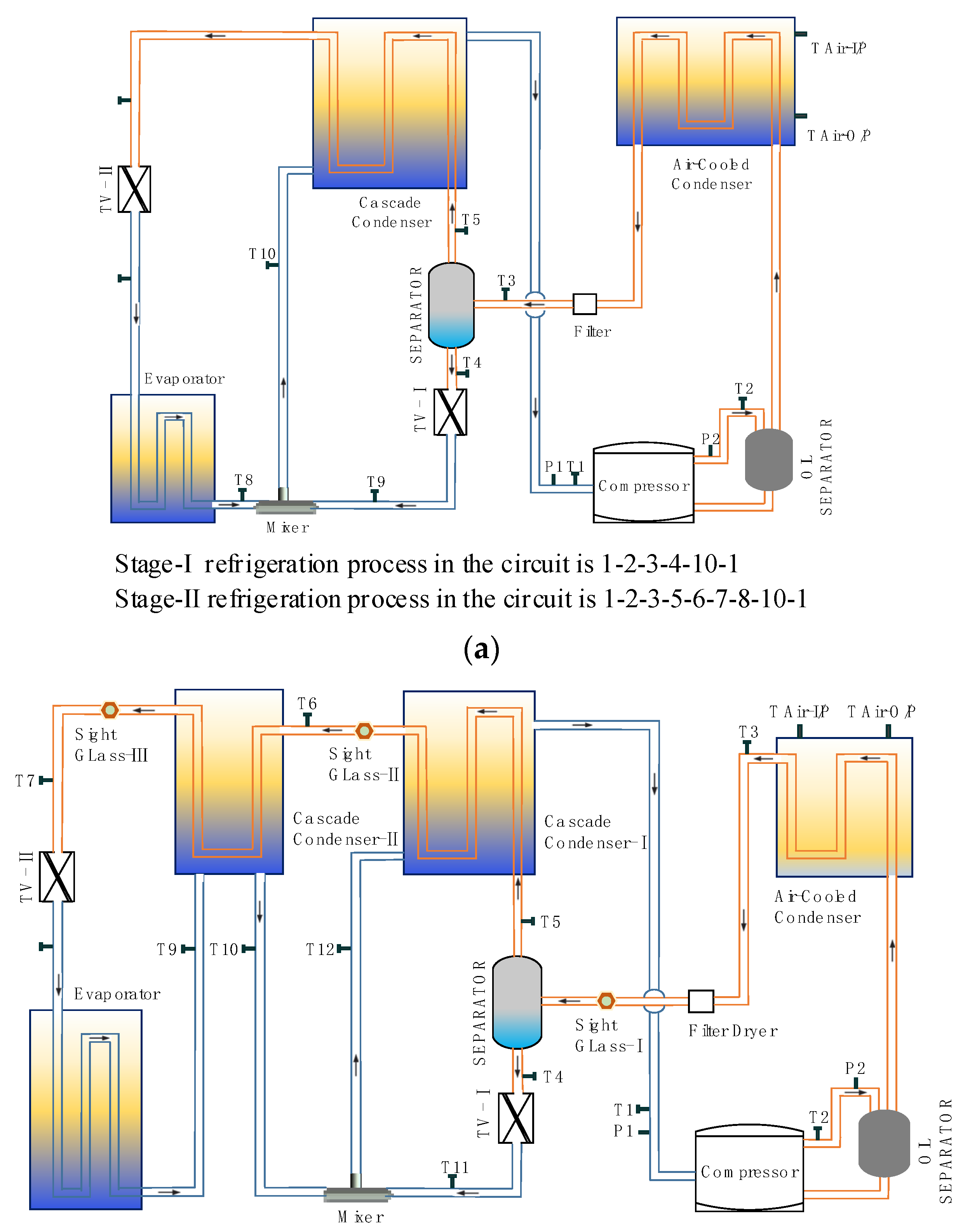
2.1. Cycle Description

Figure 1 shows the schematic diagram of the two-stage ACRC and MACRC. The two systems both comprise mainly of compressors, condensers, separators, cascade condensers, throttle valves, and evaporators. The main difference between MACRC and common ACRC is that the two-phase flow leaving cascade condenser-I can get more heat rejected before entering the throttling valve-II (TV-II). The working principle of the MACRC is as follows: The refrigerant mixture enters the compressor in a superheated state (point 1) and is compressed into a high-temperature and high-pressure vapor state (point 2). Upon entering the condenser, a large amount of high boiling point refrigeration in a gaseous zeotropic mixture is changed into a high-pressure liquid phase through a cooling and condensation process, meaning that the gaseous refrigerant entering the condenser becomes a high-pressure two-phase state before leaving the condenser. During this process, heat is ejected into the surrounding environment, and at the condenser outlet (point 3) is a gas-liquid phase with a temperature nearer to the ambient temperature. Right here is the state before entering the phase separator. The phase separator herein is equivalent to a heat distributor, and its upper and lower outlet channels divide the cycle into two parts: the high-temperature loopback and the low-temperature loopback. The liquid phase of the mixture with a higher boiling point (first refrigerant group) in this part flows out through the lower outlet of the phase separator (point 4). The first refrigerant group enters the throttle valve-I (TV-I) and is throttled to a two-phase state (point 11) to obtain a lower temperature and cooling capacity.
The gas phase of refrigerants (second refrigerant group) separated by the phase separator flows out through the top outlet (point 5). The second refrigerant group flows to the first cascade condenser and then gets further condensed by transferring heat to the counterflow of this heat exchanger. The main components of the fluid after condensation are the liquid low boiling point refrigerants (point 6). Those refrigerants enter the second cascade condenser for further condensation to obtain subcooling (point 7), making them more conducive to throttling down the temperature in the TV-II. The throttled working fluid (point 8) in two-phase passes through the evaporator to be heated by the cooled surroundings. The two-phase fluid vaporizes by absorbing heat from the medium inside of these surroundings and ultimately exit the evaporator (point 9). The gaseous refrigerants that come out of the evaporator enter the low-pressure side of the second cascade condenser and exchange heat with the refrigerants on its high-pressure side to achieve a much higher dryness (point 10). The low-pressure refrigerants vapor that flows out of the second cascade condenser joins the two-phase refrigerants that flow out of the TV-I (point 12). The combined mass fluid enters the low-pressure section of the first cascade condenser to evaporate to a higher dryness (point 1). In this process, it provides cooling to the low boiling point refrigerant gas on the counterflow side.
To analyze the thermodynamic properties of MACRC at different freezing temperatures, the given variable working condition is the evaporation temperature Te within the range of −70 °C to −65 °C. For the selection from HCs, the refrigerant R170, which has a lower triple phase point and a lower NBP than Te, was chosen as the refrigerant for the low temperatures [29]. The refrigerant R600a, commonly used as a refrigerant system, is used as the refrigerant for high temperatures. These two refrigerants together form a zeotropic mixture. However, the working pressure of R170 is very low and R170 is prone to negative evaporation in the system, which inevitably leads to ice blocks in practical applications. In addition, the low vapor pressure can cause flashing of the lubricating oil, which can lead to a loss of lubrication in the compressor, resulting in a high temperature and pressure exhaust. The refrigerant R290 can moderate the vapor pressure in the low-temperature section. A ternary zeotropic mixture of R600a/R290/R170 is used as the working fluid in this work. Some basic properties of the components are given in Table 1. These three refrigerants are flammable and classified as Class A3 in safety. It can be used in small-scale refrigeration devices with a limited refrigerant charge [30].

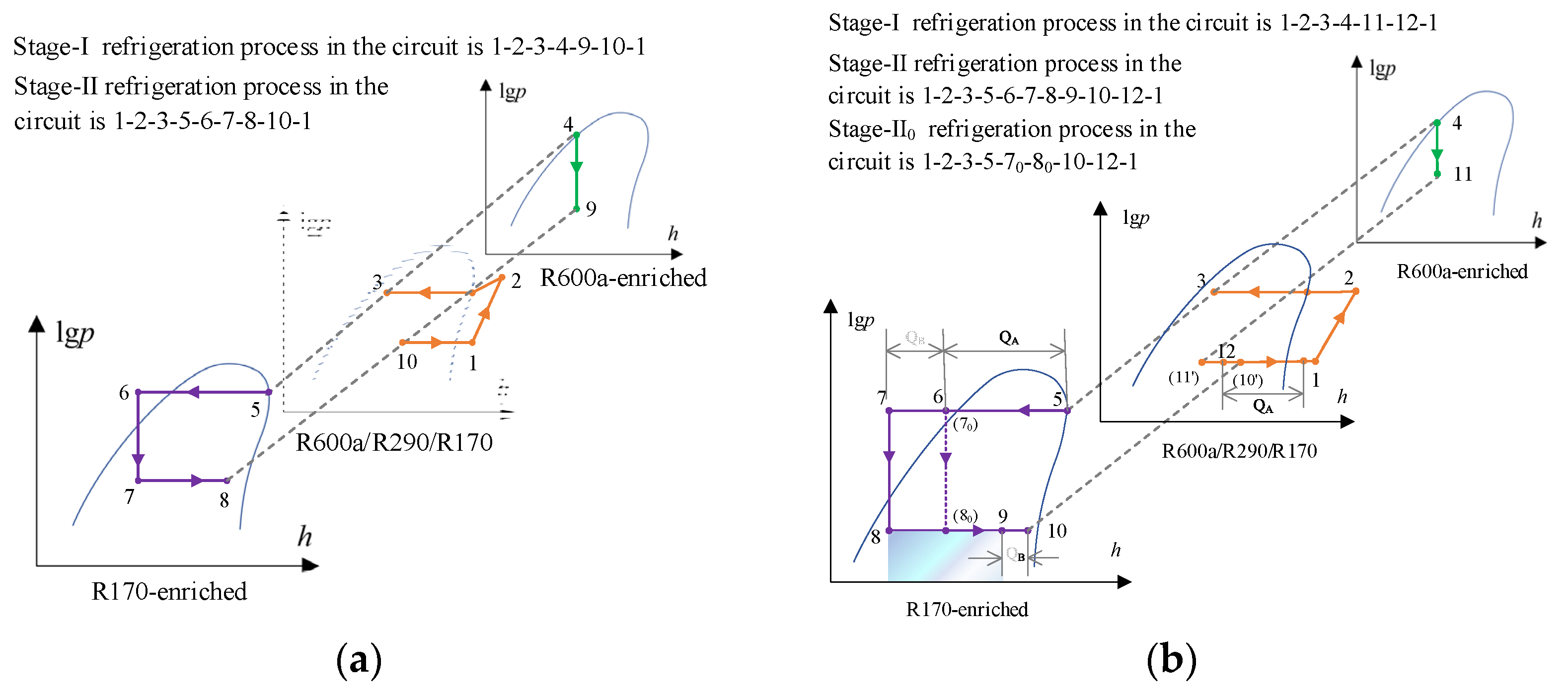
2.2. Theoretical Cycle Analysis

The automatic cascade refrigeration cycle in this work can be represented by a thermodynamic expression diagram composed of pressure-enthalpy diagrams of three planes. The pressure-enthalpy diagrams are given for ACRC and MACRC as shown in Figure 2a,b, respectively. For ACRC, the process of points 1 to 2 displays the compression of the mixture in the compressor. The process of points 2 to 3 indicates the condensation of the mixture from the superheated vapor region to the two-phase region rich in R600a after cooling. Then it is divided into two paths: one for the saturated liquid state at point 4, which is enriched with R600a; the other one is saturated vapor state point 5 where the working fluid at this state point is enriched with R170. Such working fluid flow was further divided into a two-stage pressure-enthalpy change cycle at that time. During state points 4–9, the first refrigerant group is throttled through the TV-I. The second refrigerant group flows into the first cascade condenser at point 5 and continues to be cooled and condensed to point 6. Subsequently, after being expanded through the TV-II, the second refrigerant group has a certain cooling capacity up to point 7. After flowing through the evaporator for evaporation and heat absorption, the working fluid goes to point 8 and joins with the first refrigerant group from the TV-I to point 10. The total returned refrigerants after the convergence in the low-pressure section of the cascade condenser supply the cold energy to the departure process, which absorbs heat and returns to point 1.
The modified auto-cascade refrigeration cycle is mainly characterized by an inter-stage heat exchanger where the refrigerant is re-cooled. The cooling of the last cascade condenser ensures that the low boiling point working fluid can be condensed to a lower pre-valve temperature. In an auto-cascade refrigeration cycle, the high boiling point refrigerants rarely participate the heat absorption in the evaporator. In cascade condensers, the low-pressure mixture mostly provides condensation conditions for the high-pressure mixture. The latent heat of condensation in two stages is expressed as QA and QB, respectively, as shown in Figure 2b. Part of the static pressure changes to dynamic pressure when the refrigerant fluid is throttled, the flow velocity increases drastically to aggravate the turbulent flow, and the friction resistance also increases so that the fluid reaches a pressure drop, i.e., a change in state points 7 to 8. The pressure difference between the front and rear of the throttle valve determines the evaporation refrigerant pressure and temperature in the evaporator [32,33]. The cooling capacity of the refrigerant after throttling is indicated on the pressure-enthalpy diagram. The main refrigerant subcooling through the second cascade condenser has been shown as a change in state points 6 to 7 on the pressure enthalpy diagram. In comparison with process Stage-II0, the new cycle has a larger refrigeration equivalent as shown in the pressure-enthalpy diagram.
The ACRC cycle differs from the traditional refrigeration cycle as there is a variation in the concentration of the operating medium. Figure 3 shows the enthalpy-concentration relationship of R170, the primary refrigerant in the process of evaporation in the MACRC. Points 1 to 12 refer to the states of the MACRC in Figure 1. Pk and P0 are marked to denote the condensing and evaporating pressures of the process, respectively. There are two sets of pressure curves in the diagram, i.e., the upper two represent the isobars in the gas phase, and the lower two represent the isobars in the liquid phase. The primary working refrigerant R170 goes through the cycle of 1-2-3-5-6-7-8-9-10-12-1 in Stage-II, as shown in Figure 2b. As the primary refrigerant in this system needs to fulfill the ULT requirements, the concentration of R170 after entry into Stage II is depicted on the right-hand side of the graph. At the evaporation stage, the concentration is higher. The unit cooling capacity q0 provided by the two stages is also viewed in the figure.

3. Thermodynamic Modeling

3.1. Energetic Models

The thermodynamic analysis is based on the following four model equations, independent of the flow of the whole cycle or the components: (1) mass balance equation (M equation), the total amount of working medium in the cycle remains unchanged. (2) Vapor-liquid equilibrium equation (E equation). (3) the amount of substance (molar composition) balance equation (S equation), the molar composition in the cycle does not change; (4) Energy balance equation (H equation). The above four kinds of equations together are referred to as MESH equations. This work employed thermodynamic analysis to discuss the cycle characteristics. The following assumptions were introduced to simplify the model.
(1)
All components are in steady-state operation, and binary flow is assumed homogeneous.
(2)
The specific enthalpy of the working fluid is consistent for both before and after the throttle valve, and the compression in the compressor and throttling in the throttle valve processes are irreversible and adiabatic.
(3)
Only the condenser disperses heat to the surroundings. The pressure drops in the heat exchanger and connecting pipelines are negligible.
(4)
Kinetic and potential energy changes are ignored.
The governing equations were obtained based on the above assumptions by applying energy and mass balance for each component.
The power consumption of the compressor:
W comp = m ˙ ( h 2 h 1 )
The cooling capacity of the evaporator:
Q evap = m ˙ ( h 9 h 8 )
The heat rejected by the condenser:
Q cond = m ˙ ( h 2 h 3 )
The heat was removed in the condenser-Ⅰ (hot fluid flow):
Q cas - cond - I = m ˙ RI ( h 5 h 6 )
The heat was added in the condenser-Ⅰ (cold fluid flow):
Q cas - evap - I = m ˙ ( h 12 h 1 )
The heat was removed in the condenser-Ⅱ (hot fluid flow):
Q cas - cond - II = m ˙ RI ( h 6 h 7 )
The heat was added in the condenser-Ⅱ (cold fluid flow):
Q cas - evap - II = m ˙ RI ( h 10 h 9 )
The thermodynamic performance of the ACRC system is evaluated by its COP, defined as the ratio of the cooling capacity to the power consumption of the compressor.
COP = Q evap W comp
Thermodynamic laws can be applied to determine optimal directions through equilibrium analysis, which is a process that relies on the combined analysis of the quantity and quality of energy. A thermodynamic analysis identifies defects and suggests the thermodynamic integrity of various devices and systems.

3.2. Exergic Models

The first and second laws of thermodynamics are the fundamental theoretical foundations of thermodynamic analysis. Based on the first law of thermodynamics, the second law analyzes the energy utilization and loss of each part of the system in terms of quantity and quality of energy. The exergy analysis methodology is used to analyze the loss of exergy and obtains the efficiency of the system [34]. The characteristic of this method is that exergy turns into unusable energy in the irreversible process, and the unusable energy is impossible to turn into exergy.
The imperfections and the size of the loss revealed by the two methods are different. Compared with energy analysis, exergy analysis was more scientific and reasonable in revealing the cause and location of loss and pointing out the direction of improvement. As a rule, the exergy in the thermodynamic cycle can be given as:
e x = h T 0 s
e x = ( h h 0 ) T 0 ( s s 0 )
where s0 and h0 are the entropy and enthalpy of the working fluid at ambient temperature T0, respectively.
The utmost potential for converting the energy in the form of heat and internal energy depends on the states T0 and p0 of the ambient medium. The exergy value of the environmental medium is zero, so any energy emitted into the environment cannot be accumulated and reconverted into useful work, and therefore the energy accumulated in the environment cannot be used. The calculation that energy may be converted into work in all forms is based on the environmental state.
The exergy destruction of primary components is expressed as:
E ˙ x d = m ˙ in e x in m ˙ out e x out + Q ˙ ( 1 T 0 T ) + W
For each component, the exergy destruction efficiency (μi) relative to total power consumption is given by:
μ i = E ˙ x d i W comp
The exergy destruction of each component in the MACRC can be obtained as follows:
For the compressor, the exergy loss:
E ˙ x d comp = m ˙ T 0 ( s 2 s 1 )
μ comp = E ˙ x d comp W comp
For the condenser, the exergy loss:
E ˙ x d cond = m ˙ ( h 2 T 0 s 2 ) m ˙ ( h 3 T 0 s 3 ) Q cond ( 1 T 0 T cond )
μ cond = E ˙ x d cond W comp
For the cascade condenser-I, the exergy loss:
E ˙ x d cas - cand - I = m ˙ RI ( ( h 5 h 6 ) T 0 ( s 5 s 6 ) ) + m ˙ ( ( h 12 h 1 ) T 0 ( s 12 s 1 ) )
μ cas - cond - I = E ˙ x d cas - cond - I W comp
For the cascade condenser-II, the exergy loss:
E ˙ x d cas - cand - II = m ˙ RI ( ( h 7 h 6 ) T 0 ( s 7 s 6 ) + ( h 9 h 10 ) T 0 ( s 9 s 10 ) )
μ cas - cond - II = E ˙ x d cas - cond - II W comp
For the TV-I, the exergy loss:
E ˙ x d TV - I = m ˙ RII ( ( h 4 h 11 ) T 0 ( s 4 s 11 ) )
During the throttling process in stage-I, h 4 = h 11 , Equation (21) can be written as:
E ˙ x d TV - I = m ˙ RII T 0 ( s 11 s 4 )
μ TV - I = E ˙ x d TV - I W comp
For the TV-II, the exergy loss:
E ˙ x d TV - II = m ˙ RI ( ( h 7 h 8 ) T 0 ( s 7 s 8 ) )
During the throttling process in stage-II, h 8 = h 7 , Equation (24) can be written as:
E ˙ x d TV - II = m ˙ RI T 0 ( s 8 s 7 )
μ TV - II = E ˙ x d TV - II W comp
For the evaporator, the exergy loss:
E ˙ x d evap = m ˙ RI ( h 8 T 0 s 8 ) m ˙ RI ( h 9 T 0 s 9 ) Q evap ( 1 T 0 T evap + T )
where: Δ T = 5   ° C , the temperature difference between the media in the cooled surroundings and refrigerant at the exit of the evaporator outlet, Tevap.
μ evap = E ˙ x d evap W comp
For mixer, m ˙ = m ˙ RI + m ˙ RII , the exergy loss:
E ˙ x d Mix = T 0 ( m ˙ s 12 ( m ˙ RI s 10 m ˙ RII s 11 ) )
The following equation gives overall exergy destruction in the MACRC as the sum of exergy destruction:
E ˙ x d total = E ˙ x d i
The entire exergy efficiency of the cycle is given by:
η x = 1 E ˙ x d total w ˙ comp
The thermodynamics laws analyze the direction of the process in terms of the combination of the quantity and quality of energy through equilibrium analysis. That allows imperfections in the thermodynamic process to be identified and indicates the degree of thermodynamic integrity of the various devices and systems.

4. Results and Discussion

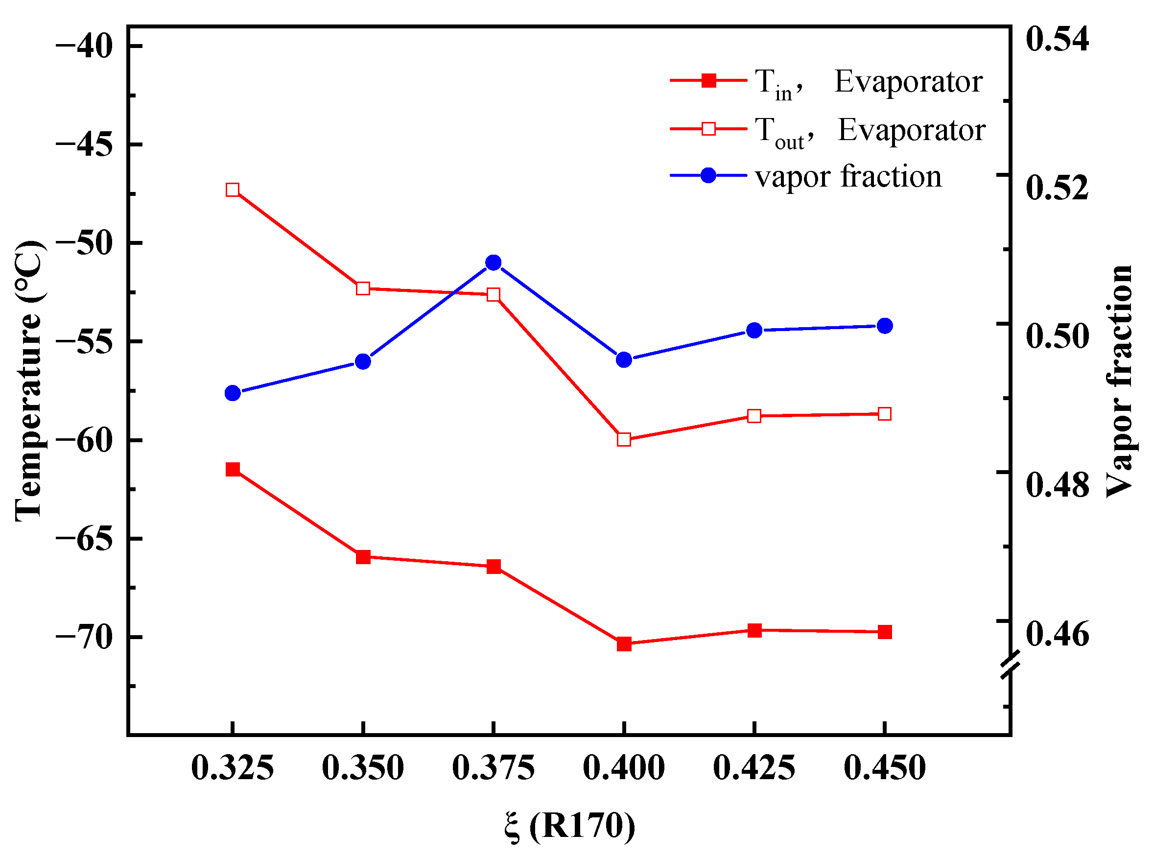
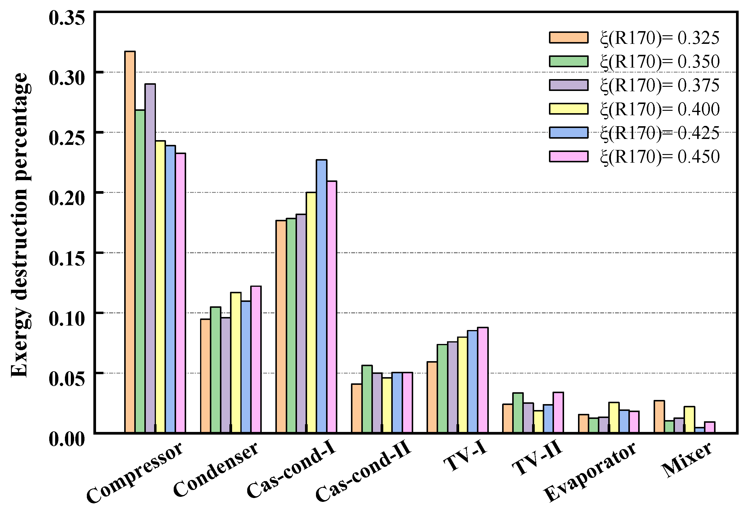
4.1. Performance under a Typical Operating Condition with Initial Composition

The vapor-liquid phase calculation uses the Peng-Robinson (PR) equation, which is more accurate in calculating the liquid density [35]. The modelling calculation process is conducted by Aspen Plus.11, which is employed to evaluate the system performance. In this work, the system characteristics of the MACRC system are investigated when the refrigerant R600a/R290/R170 provides a cooling capacity of 500 W. Considering the influence of parameters, we chose to set constant the highest boiling point refrigerant, and step change the ratio of medium and low-temperature refrigerant. The calculation results for several different initial components as shown in Table 2.
Figure 4 shows the changes in evaporator inlet temperature, outlet temperature, and vapor fraction at different concentrations of low boiling point refrigerant R170 (0.325–0.450). From the graph, the inlet temperature of the evaporator shows a downward trend as the concentration of R170 increases. As a result of the increased mass fraction of R170 in the entire ULT system, the flow into the stage-II has increased, and there is less influence from the pressurization of the higher concentration refrigerant. It allows the low boiling point refrigerant to pass through the throttle valve, resulting in a reduction in temperature at the rear of the valve.
Through further analysis, it is noted from the graph that at low concentrations of low- temperature refrigerants, the evaporator outlet temperature is generally 15 °C over inlet temperature. It also indicates that the temperature glides at 15 °C under the cooling demand. As the mass fraction of low-temperature refrigerant R170 increases, the degree of temperature glide decreases. The principal reason is that the main refrigerant involved in stage-II of the MACRC is R170. The increase in the percentage of R170 moderates the extent of the variation in evaporation temperature change. The vapor fraction at the evaporator outlet tends to increase and then decrease as the R170 percentage ratio increases. This trend is of a similar nature to the direction in evaporator inlet and outlet temperatures when the R170 percentage is greater than 0.4. The outlet vapor phase fraction of the evaporator at several concentration percentages is around 0.5, which is of a lower value. In general, the evaporator outlet temperatures have reached below −60 °C, but the demand for dropping to −65 °C still has to be at a higher mass fraction of R170.
The variation in exergy efficiency for each system component at different concentrations is displayed in Figure 5. The compressor has the most exergy destruction, followed by the cascade condenser-I, which has more exergy destruction than that of the condenser. Accordingly, the cascade condenser requires more amount of condensing energy. The exergy destruction percentage of the cascade condenser-I increases as the mass fraction of R170 increases. The exergy destruction percentage of the compressor decreases as the percentage of the low-temperature refrigerant concentration increases in the MACRC system, yielding a larger concentration of cryogenic refrigerant demand when taking into account only the efficiency of the compressor. Furthermore, comparing two cascade heat exchangers, the heat transfer of the first one is more than that of the second, resulting from the exergy destruction percentage.
The variations in COP, exergy efficiency, and outlet vapor fraction of the evaporator at different concentrations of cryogenic refrigerant are displayed in Figure 6. In the low-temperature process, with increasing the mass fraction of R170 in this MACRC system, the power consumption increases, and the highest efficiency is obtained at the concentration of 0.35. The COP, however, is highest at a concentration of 0.375. The exergy efficiency and COP reduce with increasing the mass fraction of R170 beyond the two highest points. The reason is a higher content of the primary refrigerant increases the power consumption and heat removal of the compressor. Considering the above presentations and combining these two thermodynamic performances, the need for a lower vapor fraction at the evaporator outlet is the best option. A relatively positive thermodynamic performance is presented when the refrigerant R600a/R290/R170 with a mass fraction of 0.25/0.35/0.40. It is known from Table 1 that at this initial refrigerant composition, the suction temperature of the compressor is −13.1 °C. The higher suction temperature ensures the safe operation of the compressor. Meanwhile, the inlet temperature of the evaporator is −65.9 °C, which meets the temperature requirements of the ULT. When the compact MACRC system is applied indoors, the ambient temperature is within the range of 20 to 40 °C. We investigated the cycle characteristics under different ambient temperatures when the initial refrigerant composition is the best.

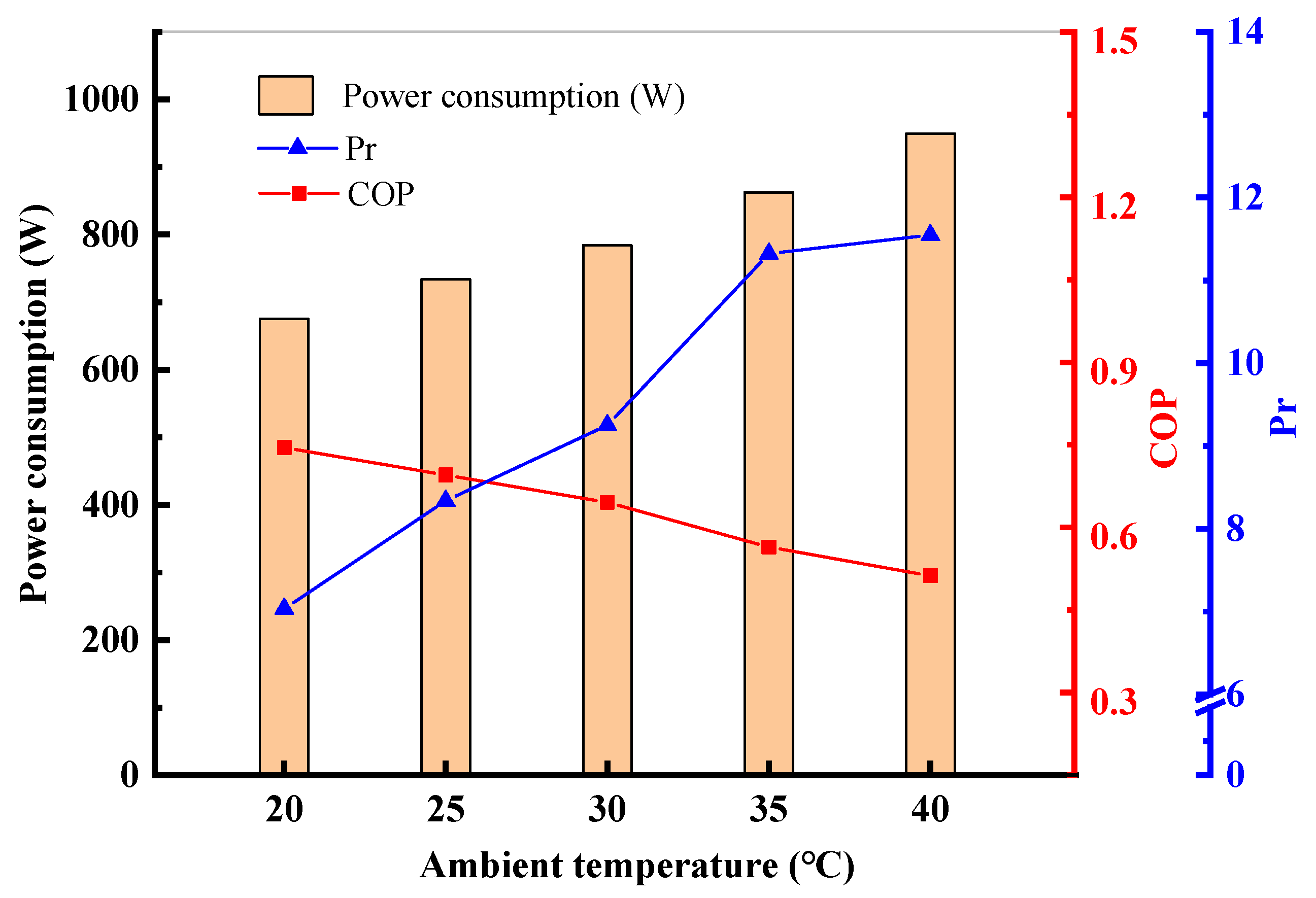
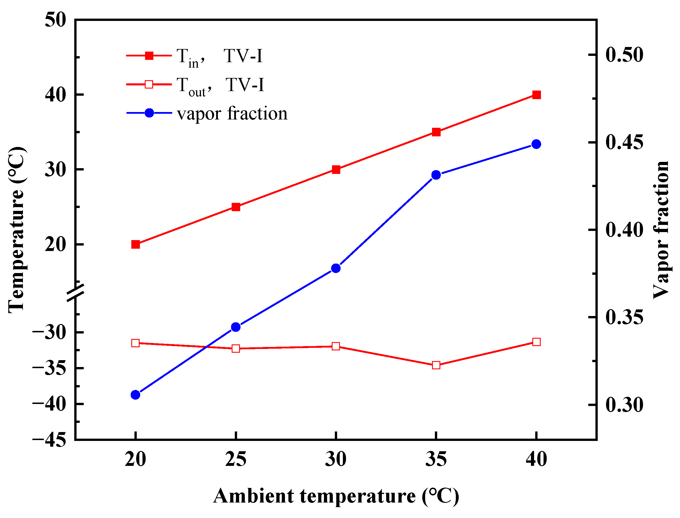
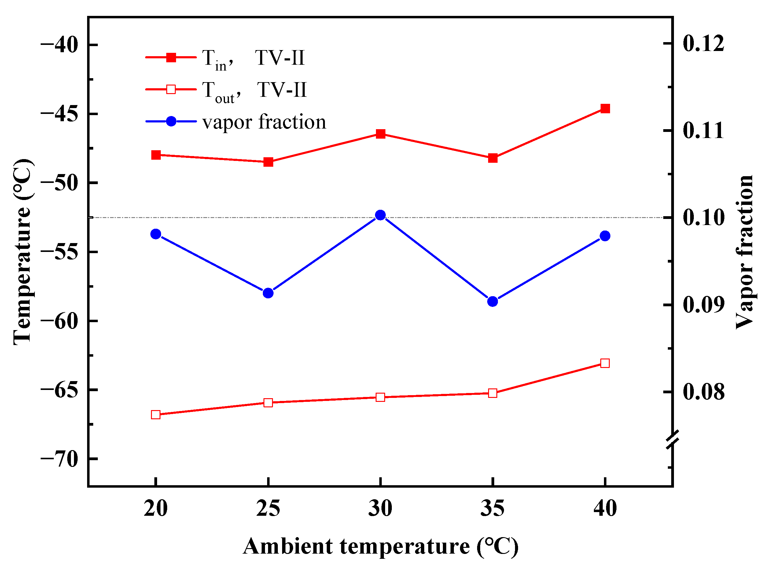
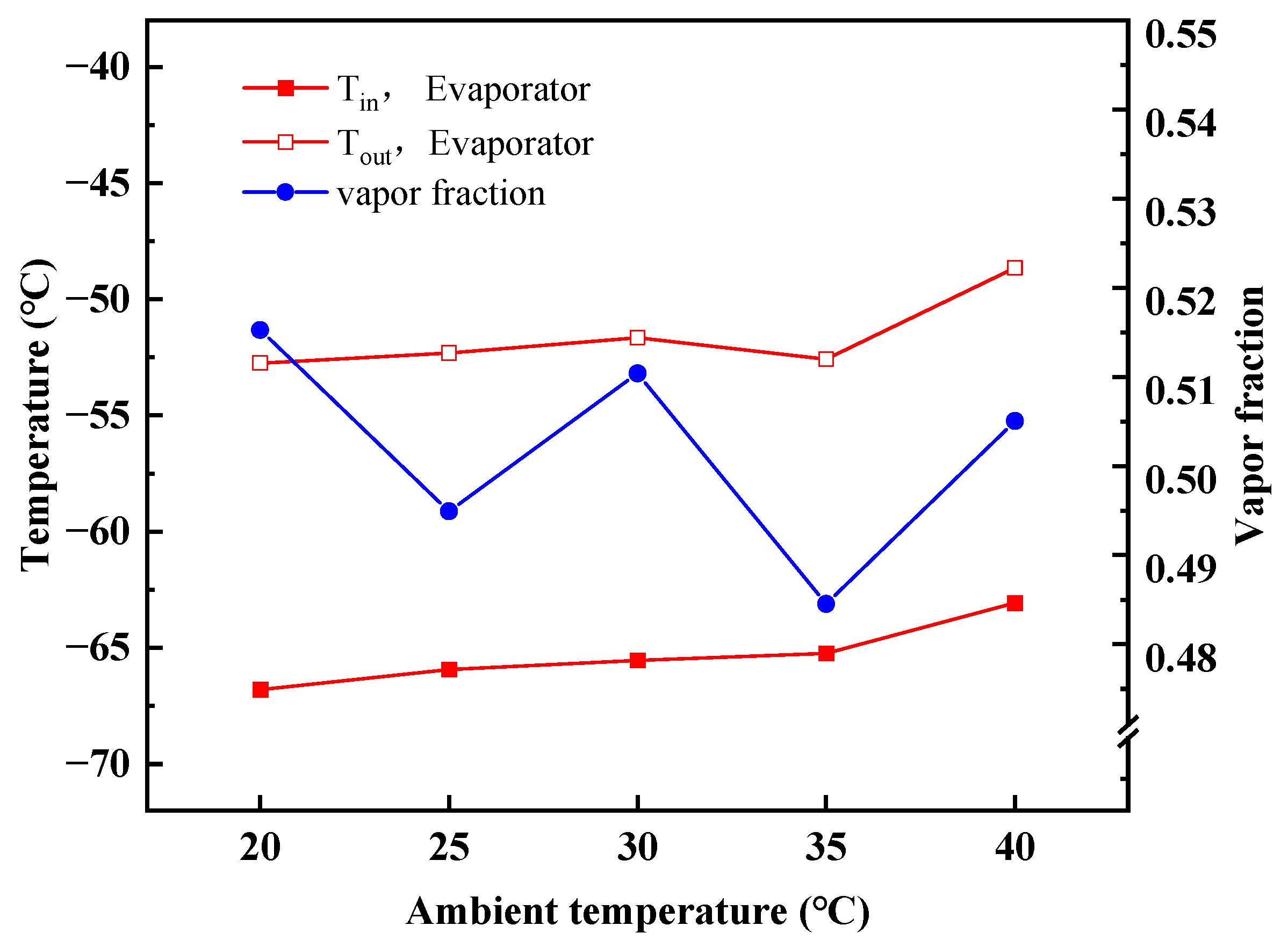
4.2. Performance Variations with Ambient Temperature

Both the temperature at the condenser outlet and the phase separator internal approximates the ambient temperature. The compressor power consumption increases as the ambient temperature rise, as shown in Figure 7. It could also account for the decrease in COP with increasing ambient temperature. The increased ambient temperature results in an increased temperature and pressure at compressor discharge. As a result, the ratio of high to low pressure in the cycle tends to increase as the ambient temperature rises. Numerically, the COP of the MACRC is over 0.4, and the pressure ratio is less than 12.
Figure 8 shows the variation in exergy loss for each component at different ambient temperatures when the ternary refrigerants R600a/R290/R170 with the mass fraction of 0.25/0.4/0.35. The graph indicates that the compressor does maintain the most evident exergy loss. The exergy destruction of the cascade condenser-I is greater than that of the condenser. The energy that may be converted into useful work of the three mentioned components above would decrease as the ambient temperature rises. But the exergy destruction of the evaporator is almost unchanged. The exergy destruction of the first throttle valve is greater than that of the second one. Compared with the previous one, the exergy loss of the second cascade condenser is minor, and which trend is similar to that of evaporators. All these trends indicate that the exergy destruction of components is merely independent of the ambient temperature in stage-II.
Figure 9 shows the throttling-related variations parameter in the first refrigeration stage. In this part, the inlet temperature of TV-I is close to the temperature in the phase separator, i.e., it approaches the ambient temperature. After throttling, the low pressure is 1.6 bar, and the outlet temperature is below −30 °C. As the ambient temperature increases, the temperature after throttling decreases as the concentration of high boiling working fluid in the phase separator becomes larger after the ambient temperature rises. The condensed liquid of R600a and R290, which is almost free of non-condensable gases, flows out of the liquid outlet of the phase separator. Most of them flowed to the first throttle valve. The vapor fraction at the throttle outlet changes from 0.3 to 0.45, which is the scenario of throttling flash in the refrigeration system. The temperature difference between the inlet and outlet of the throttle valve increases as the ambient temperature increases, and the gas content of the outlet in the two-phase region increases, as shown in the pressure-enthalpy diagram previously discussed. The two-phase refrigerant with a certain liquid phase is blended with the backflow fluid from stage-II. It enters the evaporating side of the first cascade condenser to achieve the effect of condensing heat flow.
The outlet temperature of the second throttle valve increases as the ambient temperature rises, as shown in Figure 10. Influenced by the outlet temperature of the cascade condenser-I, the inlet temperature of the TV-II is below −45 °C. After the refrigerant passes through the TV-II, the vapor fraction becomes smaller, indicating that the fluid is close to the liquid phase. The vapor fraction of the refrigerant is below 0.1, ensuring the phase change in the evaporator absorbs heat for cooling. At lower ambient temperatures, the outlet temperature of the TV-II can reach below −65 °C, which is also the temperature of the refrigerant entering the evaporator. When the ambient temperature increases gradually, altering the inlet temperature of the evaporator so that the heat transfer temperature difference between the evaporator and the cooled space gradually decreases, and the cooling effectiveness deteriorates. It indicates that the ambient temperature should be controlled to be not excessively high to ensure reasonable low-temperature working requirements.
Figure 11 shows the thermal parameters of the evaporator as the ambient temperature changes. The evaporator, specifically its cold end, has a relatively constant temperature at the inlet and outlet, increasing as the ambient temperature increases, indicating inadequate thermodynamic performance. The outlet vapor fraction of the evaporator is approximately 0.5, meaning a positive latent heat of the working fluid. The lower vapor fraction ensures the cooling capacity of the cold end. The refrigerant with a certain percentage of liquid phase enters the evaporative side of the second cascade condenser to cool the hot flow.

5. Conclusions

A two-stage modified auto-cascade refrigeration cycle for small ULT systems was proposed. The orientations are to improve the performance of the system with a certain amount of energy consumption and cooling demand. The ternary mixture with temperature glide and composition variation is employed in this MACRC system. To date, there has been little work to introduce ternary refrigerants into two-stage auto-cascade refrigeration systems. In this work, the exergy and performance analyses of the MACRC system were carried out.
(1)
The MACRC system introduces a subcooled cascade condenser-II, which enables the refrigerant entering stage-II to obtain a greater cooling capacity. This method without complex mechanical components is more suitable for application in practice.
(2)
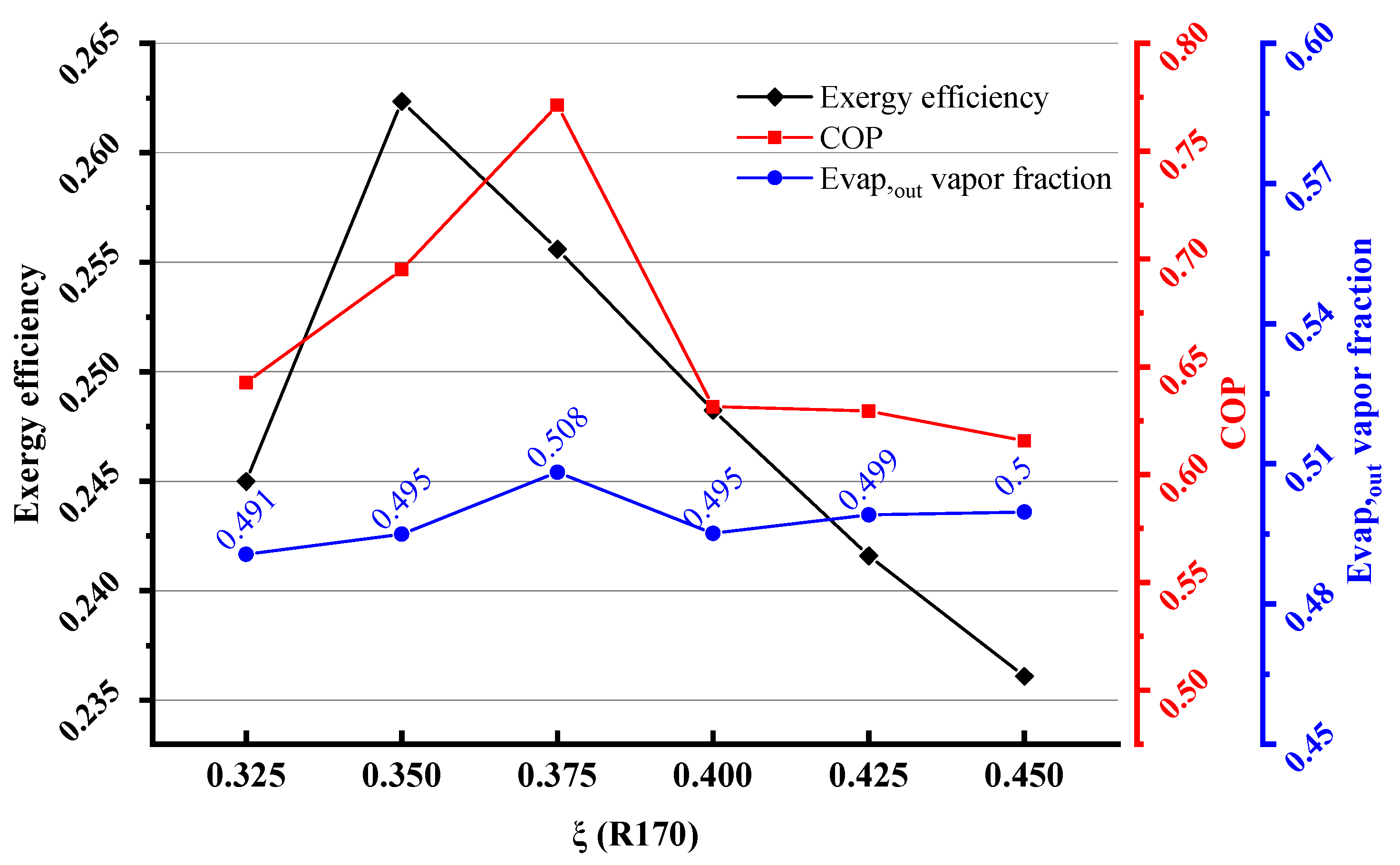
The ternary mixture of R600a/R290/R170 of the mass fraction of 0.25/0.35/0.40 having a coefficient of performance of 0.695 and an exergy efficiency of 0.262 was recommended for the MACRC system.
(3)
With increasing ambient temperatures, the outlet temperature of TV-I in stage-I is almost constant, whereas the outlet temperature of TV-II in stage-II goes up. The MACRC system can achieve −65 °C when the ambient temperature is less than 35 °C.
The auto-cascade refrigeration system is inherently self-regulating so that the cold end will meet the demands of the application. The MCRAC system theoretically shows its advantages for applications at the temperature level of −60 °C. Further theoretical and experimental work is expected to validate the potential of the proposed cycle in terms of improved performance.

Author Contributions

Conceptualization, Z.L., J.J., Z.W. and H.Z.; methodology, Z.L., Z.W.; software, Z.L. and Z.W.; validation, Z.L.; formal analysis, Z.L.; investigation, Z.L. and Z.W.; resources, Z.L. and J.J.; data curation, Z.L. and Z.W.; writing—original draft preparation, Z.L.; writing—review and editing, Z.L.; visualization, Z.L.; supervision, H.Z.; project administration, Z.W.; funding acquisition, Z.W. and H.Z. All authors have read and agreed to the published version of the manuscript.

Funding

This research was funded by the Shanghai Municipal Natural Science Foundation (20ZR1438600), the Special Project of Biomedical Science and Technology Support of Shanghai Science and Technology Innovation Action Plan (21S31900200), the Open Project of the Shanghai Key Laboratory of Multiphase Flow and Heat Transfer in Power Engineering and the Central Guidance on Local Science and Technology Development Fund of Shanghai City (No. YDZX20213100003002), the Special Project of Independent Innovation of Qingdao City (21-1-2-6-NSH). And The APC was funded by the Shanghai Municipal Natural Science Foundation (20ZR1438600).

Data Availability Statement

Not applicable.

Conflicts of Interest

The authors declare that they have no known competing financial interests or personal relationships that could have appeared to influence the work reported in this paper.

Nomenclature

AbbreviationsSubscripts
ULTultra-low temperatureincomponent inlet side
ACRCauto-cascade refrigeration cycleoutcomponent outlet side
MACRCmodified auto-cascade refrigeration cyclecompcompressor
COPcoefficient of performanceRIfirst refrigerant group
TVthrottle valveRIIsecond refrigerant group
NBPnomal boiling pointevapevaporator
condcondenser
Symbols cas-condcascade condenser
Qheat capacity of heat exchanger (W)cas-evapcascade evaporator
hspecific enthalpy (J·kg−1)0reference state
sspecific entropy (J·kg−1·K−1)1–12state points
m ˙ mass flow rate (kg·s−1))icycle components
exspecific exergy (J·kg−1)
qunit cooling capacity (W)Greek letters
E ˙ xdexergy destruction (W)ξmass fraction
Wpower consumption (W)μexergy destruction efficiency
Prpressure ratio of compressor (-)ηexergy efficiency
Ppressure (bar)
Ttemperature (°C)

References

  1. Miyara, A.; Onaka, Y.; Koyama, S. Ways of Next Generation Refrigerants and Heat Pump/Refrigeration Systems. Int. J. Air-Cond. Refri. 2012, 20, 1130002. [Google Scholar] [CrossRef]
  2. Li, D.; Wu, Y.; Wang, B.; Liu, C.; Arıcı, M. Optical and thermal performance of glazing units containing PCM in buildings: A review. Constr. Build. Mater. 2020, 233, 117327. [Google Scholar] [CrossRef]
  3. Tolstorebrov, I.; Eikevik, T.M.; Bantle, M. Effect of low and ultra-low temperature applications during freezing and frozen storage on quality parameters for fish. Int. J. Refrig. 2016, 63, 37–47. [Google Scholar] [CrossRef]
  4. Mota-Babiloni, A.; Joybari, M.M.; Navarro-Esbrí, J.; Mateu-Royo, C.; Barragán-Cervera, Á.; Amat-Albuixech, M.; Molés, F. Ultralow-temperature refrigeration systems: Configurations and refrigerants to reduce the environmental impact. Int. J. Refrig. 2020, 111, 147–158. [Google Scholar] [CrossRef]
  5. Bai, T.; Li, D.; Xie, H.; Yan, G.; Yu, J. Experimental research on a Joule-Thomson refrigeration cycle with mixture R170/R290 for −60 °C low-temperature freezer. Appl. Therm. Eng. 2021, 186, 116476. [Google Scholar] [CrossRef]
  6. Qin, Y.; Li, N.; Zhang, H.; Liu, B. Thermodynamic performance of a modified −150 °C refrigeration system coupled with Linde-Hampson and three-stage auto-cascade using low-GWP refrigerants. Energ. Convers. Manag. 2021, 236, 114093. [Google Scholar] [CrossRef]
  7. Xu, X.; Liu, J.; Cao, L. Mixed refrigerant composition shift due to throttle valves opening in auto cascade refrigeration system. Chinese. J. Chem. Eng. 2015, 23, 199–204. [Google Scholar] [CrossRef]
  8. Gao, Y.; He, G.; Cai, D.; Fan, M. Performance evaluation of a modified R290 dual-evaporator refrigeration cycle using two-phase ejector as expansion device. Energy 2020, 212, 118614. [Google Scholar] [CrossRef]
  9. Bai, T.; Yan, G.; Yu, J. Experimental research on the pull-down performance of an ejector enhanced auto-cascade refrigeration system for low-temperature freezer. Energy 2018, 157, 647–657. [Google Scholar] [CrossRef]
  10. Bai, T.; Yan, G.; Yu, J. Experimental investigation of an ejector-enhanced auto-cascade refrigeration system. Appl. Therm. Eng. 2018, 129, 792–801. [Google Scholar] [CrossRef]
  11. Bai, T.; Yan, G.; Yu, J. Experimental investigation on the dynamic malfunction behavior of the two-phase ejector in a modified auto-cascade freezer refrigeration system. Energ. Convers. Manag. 2019, 183, 382–390. [Google Scholar] [CrossRef]
  12. Yu, M.; Yu, J. Thermodynamic analyses of a flash separation ejector refrigeration cycle with zeotropic mixture for cooling applications. Energ. Convers. Manag. 2021, 229, 113755. [Google Scholar] [CrossRef]
  13. Elbel, S.; Lawrence, N. Review of recent developments in advanced ejector technology. Int. J. Refrig. 2016, 62, 1–18. [Google Scholar] [CrossRef]
  14. Wang, Q.; Cui, K.; Sun, T.-F.; Chen, G.-M. Performance of a single-stage auto-cascade refrigerator operating with a rectifying column at the temperature level of −60 °C. J. Zhejiang. Univ.-Sci. A 2011, 12, 139–145. [Google Scholar] [CrossRef]
  15. Wang, Q.; Liu, R.; Wang, J.; Chen, F.; Han, X.; Chen, G. An investigation of the mixing position in the recuperators on the performance of an auto-cascade refrigerator operating with a rectifying column. Cryogenics 2012, 52, 581–589. [Google Scholar] [CrossRef]
  16. Liu, J.; Liu, Y.; Yan, G.; Yu, J. Theoretical study on a modified single-stage autocascade refrigeration cycle with auxiliary phase separator. Int. J. Refrig. 2021, 122, 181–191. [Google Scholar] [CrossRef]
  17. Zhang, L.; Xu, S.; Du, P.; Liu, H. Experimental and theoretical investigation on the performance of CO2/propane auto-cascade refrigerator with a fractionation heat exchanger. Appl. Therm. Eng. 2015, 87, 669–677. [Google Scholar] [CrossRef]
  18. Gurudath Nayak, H.; Venkatarathnam, G. Performance of an auto refrigerant cascade refrigerator operating in liquid refrigerant supply (LRS) mode with different cascade heat exchangers. Cryogenics 2010, 50, 720–727. [Google Scholar] [CrossRef]
  19. Sobieraj, M.; Rosiński, M. High phase-separation efficiency auto-cascade system working with a blend of carbon dioxide for low-temperature isothermal refrigeration. Appl. Therm. Eng. 2019, 161, 114149. [Google Scholar] [CrossRef]
  20. Yan, G.; Hu, H.; Yu, J. Performance evaluation on an internal auto-cascade refrigeration cycle with mixture refrigerant R290/R600a. Appl. Therm. Eng. 2015, 75, 994–1000. [Google Scholar] [CrossRef]
  21. Asgari, S.; Noorpoor, A.R.; Boyaghchi, F.A. Parametric assessment and multi-objective optimization of an internal auto-cascade refrigeration cycle based on advanced exergy and exergoeconomic concepts. Energy 2017, 125, 576–590. [Google Scholar] [CrossRef]
  22. Boyaghchi, F.A.; Asgari, S. A comparative study on exergetic, exergoeconomic and exergoenvironmental assessments of two internal auto-cascade refrigeration cycles. Appl. Therm. Eng. 2017, 122, 723–737. [Google Scholar] [CrossRef]
  23. Du, K.; Zhang, S.; Xu, W.; Niu, X. A study on the cycle characteristics of an auto-cascade refrigeration system. Exp. Therm. Fluid. Sci. 2009, 33, 240–245. [Google Scholar] [CrossRef]
  24. Sivakumar, M.; Somasundaram, P. Exergy and energy analysis of three stage auto refrigerating cascade system using Zeotropic mixture for sustainable development. Energ. Convers. Manag. 2014, 84, 589–596. [Google Scholar] [CrossRef]
  25. Rui, S.; Zhang, H.; Zhang, B.; Wen, D. Experimental investigation of the performance of a single-stage auto-cascade refrigerator. Heat. Mass. Transfer. 2015, 52, 11–20. [Google Scholar] [CrossRef]
  26. Park, W.Y.; Shah, N.; Vine, E.; Blake, P.; Holuj, B.; Kim, J.H.; Kim, D.H. Ensuring the climate benefits of the Montreal Protocol: Global governance architecture for cooling efficiency and alternative refrigerants. Energy. Res. Soc. Sci. 2021, 76, 102068. [Google Scholar] [CrossRef]
  27. Aktemur, C.; Ozturk, I.T.; Cimsit, C. Comparative energy and exergy analysis of a subcritical cascade refrigeration system using low global warming potential refrigerants. Appl. Therm. Eng. 2021, 184, 116254. [Google Scholar] [CrossRef]
  28. Rodríguez-Jara, E.Á.; Sánchez-de-la-Flor, F.J.; Expósito-Carrillo, J.A.; Salmerón-Lissén, J.M. Thermodynamic analysis of auto-cascade refrigeration cycles, with and without ejector, for ultra low temperature freezing using a mixture of refrigerants R600a and R1150. Appl. Therm. Eng. 2022, 200, 117598. [Google Scholar] [CrossRef]
  29. Li, D.; Bai, T.; Yu, J. Thermodynamic performance optimization and analysis of an auto-cascade refrigeration cycle with vapor injection for ultra-low temperature freezer. Int. J. Refrig. 2022, 145, 425–435. [Google Scholar] [CrossRef]
  30. Bai, T.; Yan, G.; Yu, J. Influence of internal heat exchanger position on the performance of ejector-enhanced auto-cascade refrigeration cycle for the low-temperature freezer. Energy 2022, 238, 121803. [Google Scholar] [CrossRef]
  31. Faruque, M.W.; Uddin, M.R.; Salehin, S.; Ehsan, M.M. A Comprehensive Thermodynamic Assessment of Cascade Refrigeration System Utilizing Low GWP Hydrocarbon Refrigerants. Int. J. Thermofluids 2022, 15, 100177. [Google Scholar] [CrossRef]
  32. Gill, J.; Singh, J. Adaptive neuro-fuzzy inference system approach to predict the mass flow rate of R-134a/LPG refrigerant for straight and helical coiled adiabatic capillary tubes in the vapor compression refrigeration system. Int. J. Refrig. 2017, 78, 166–175. [Google Scholar] [CrossRef]
  33. Sobieraj, M. Experimental Investigation of the Effect of a Recuperative Heat Exchanger and Throttles Opening on a CO2/Isobutane Autocascade Refrigeration System. Energies 2020, 13, 5285. [Google Scholar] [CrossRef]
  34. Wang, J. Modern thermodynamics—New concepts based on the second law of thermodynamics. Prog. Nat. Sci. 2009, 19, 125–135. [Google Scholar] [CrossRef]
  35. Huber, M.L.; Lemmon, E.W.; Bell, I.H.; McLinden, M.O. The NIST REFPROP Database for Highly Accurate Properties of Industrially Important Fluids. Ind. Eng. Chem. Res. 2022, 61, 15449–15472. [Google Scholar] [CrossRef] [PubMed]
Figure 1. (a) The schematic diagram of the ACRC; (b) The schematic diagram of the MACRC.
Energies 16 02282 g001
Figure 2. Pressure-enthalpy diagrams of ACRC (a) and MACRC (b) using R600a/R290/R170. (The yellow lines represent the overall circulation in the process, the green lines represent the stage-I part with R600a-enriched, and the purple lines represent the stage-II part with R170-enriched.)
Energies 16 02282 g002
Figure 3. Concentration-enthalpy diagram of the MACRC.
Energies 16 02282 g003
Figure 4. Parameter changes in and out of the evaporator.
Energies 16 02282 g004
Figure 5. The components’ exergy destruction percentage at different concentrations.
Energies 16 02282 g005
Figure 6. The coefficient of performance, exergy efficiency, and outlet vapor fraction of evaporator at different concentrations.
Energies 16 02282 g006
Figure 7. The compressor power consumption, coefficient of performance, and ratio of pressure change at different ambient temperatures.
Energies 16 02282 g007
Figure 8. The exergy destruction changes of each component at different ambient temperatures.
Energies 16 02282 g008
Figure 9. Parameters on the first throttle valve at different ambient temperatures.
Energies 16 02282 g009
Figure 10. Parameters on the second throttle valve at different ambient temperatures.
Energies 16 02282 g010
Figure 11. Parameters on the evaporator at different ambient temperatures.
Energies 16 02282 g011
Table 1. Physical properties of refrigerants [25,31].
RefrigerantMolecular FormulaMolecular Weight
(g·mol−1)
ODPGWP100-yr
(CO2-eq)
NBP (K)Freezing Point (K)Critical temp. (K)Critical Press. (MPa)ASHRAE Safety Group
R600aC4H1058.12020261.4113.7407.813.629A3
R290CH3CH2CH344.103231.0485.53369.894.251A3
R170C2H630.07020184.5790.368305.324.872A3
Table 2. The performance comparisons between different initial components.
Components
(R600a/R290/R170)
0.25/0.425/0.3250.25/0.40/0.350.25/0.375/0.3750.25/0.35/0.4000.25/0.325/0.4250.25/0.3/0.450
COP0.6340.6950.7710.6310.6290.626
Exergy efficiency (%)0.2450.26202560.2480.2420.236
Temperature in °C
Compressor inlet−15.7−13.1−14.5−17.5−14.0−13.2
Compressor outlet93.896.090.3102.8100.2105.3
Evaporator inlet−61.5−65.9−66.4−70.3−69.7−69.7
Evaporator outlet−47.3−52.3−52.6−60.0−58.8−58.7
Disclaimer/Publisher’s Note: The statements, opinions and data contained in all publications are solely those of the individual author(s) and contributor(s) and not of MDPI and/or the editor(s). MDPI and/or the editor(s) disclaim responsibility for any injury to people or property resulting from any ideas, methods, instructions or products referred to in the content.

