Communication

Sensitivity Analysis of the Complex Dynamics of an Expansion Process in Low-Pressure Compressed Air for an Electrical Energy Storage System

1
Department of Thermal and Fluid Flow Machines, Faculty of Energy and Fuels, AGH University of Science and Technology, Al. Mickiewicza 30, 30-059 Krakow, Poland
2
Department of Mechanical Engineering, Shibaura Institute of Technology, 3-7-5 Toyosu, Koto-ku, Tokyo 135-8548, Japan
*
Author to whom correspondence should be addressed.
Energies 2023, 16(5), 2310; https://doi.org/10.3390/en16052310
Submission received: 7 December 2022 / Revised: 14 February 2023 / Accepted: 22 February 2023 / Published: 28 February 2023
(This article belongs to the Special Issue Advanced Fluid Power and Mechatronics)

Abstract

:
This study presents the research and development possibilities of an expander for compressed air energy storage systems (CAES). The computer simulations made by the authors aim to find the optimal working parameters of the piston engine. The criteria for evaluating engine operation and the objects of analysis are the compressed air engine system’s efficiency and the electrical power output. Sensitivity analysis was performed on well-suited system parameters and geometrical sizes of the energy utilisation element. Appropriate selection achieves not only higher efficiency but also allows the system to be scaled to the end-user’s needs.

1. Introduction

Energy storage is essential for proper operation of a power system. The irregularity of energy production from renewable energy sources requires using systems that can cope with fluctuations [1]. Among the many energy storage systems, pumped hydro-storage (PHS), Li-ion batteries, and compressed air energy storage (CAES) seem to be the most promising. Each system has its own advantages and disadvantages. A pumped storage power plant requires huge investments and cannot be built on a small scale. On the other hand, Li-ion batteries struggle with material and environmental issues, as well as battery damage during full discharge and low power range [2,3]. CAES is a technology that allows you to build storage on any scale [4,5,6]. The durability, long discharge time and scalability are advantages of CAES over other energy storage methods [4,5,6]. CAES projects have been implemented in China, USA, Germany and Canada [3,7,8]. The challenge facing today’s engineers and scientists is to achieve total CAES efficiency. Depending on the technology and the scale of theoretical values, the efficiency ranges between 30% and 70%. Experimental studies on CAES systems are scarce in the literature. Efficiencies obtained during experimental tests usually oscillate around 45% [4,9]. An interesting and promising solution is the adiabatic energy storage of compressed air (ACAES), in which the heat generated during air compression is recovered by a heat exchanger and stored. Heat is used during the energy utilisation process, i.e., air expansion. Barbour et al. [10] presented development opportunities and challenges faced by scientists and constructors. In their article, they pointed out that one of the critical aspects of CAES development is continuous research at the university level and extending access to the results of currently operating projects.
In the literature, CAES consists of four elements (storage tank, compressor, utilisation element, generator), each of which are being examined. There are descriptions of constant-pressure tanks [11] and constant-volume tanks [12]. The authors [13] presented a tank system that maintains constant pressure due to the water system. When air from the tank is used, water is supplied to the interior to reduce the volume occupied by the air and thus maintain a constant pressure. It is known that using the hydrostatic pressure of the water column is also a method to maintain constant pressure [14]. The paper [14] shows the concept of an isobaric storage device in which energy savings are equal to 18% compared to an isochoric storage system. With the use of the presented moving piston prototype, the stable pressure was kept within 2.14%. Budt et al. [15] submitted a review showing the possibilities of storing energy in compressed air. They noted that there are still no well-developed machines that would allow CAES to operate properly and efficiently. Continuous development and exploration may benefit CAES technology due to its economic aspects and the possibility of using geological conditions such as mine shafts or salt shafts as storage space. However, the authors [15], did not present the option of using reciprocating piston machines as an element of energy utilisation, which can also be economically cheap and, with further development, highly effective. Although most articles on CAES systems are based on the use of a turbine as an expander [4,13,16], it should be noted that in the case of low-volume flows and low pressure, a positive reciprocating engine seems to be a better solution. Optimal adjustment of the expander to the value of desired power, supply pressure, or the size of the storage scale is necessary to obtain the best system operation results [17].
In the literature or as a subject of scientific research, piston expanders are rarely considered utilisation elements for CAES systems. This article presents an analysis of the geometrical parameters and their impact on the performance/characteristics of the compressed air expander. The presented results will show the expander’s power and efficiency possibilities, depending on the individual element size selection.

2. Materials and Methods

2.1. Mathematical Model

The mathematical model of expander (shown in Figure 1) performance is described by ordinary differential equations, including the mass balance equation in the actuator’s chamber and air tank, the dynamic equation for the rectilinear motion of the piston and angular motion of the generator shaft, and Kirchoff’s law of electrical circuits.
Model equations are shown below:
d m 1 d t = m ˙ 1 d m 2 d t = m ˙ 2 d m t a n k d t = m ˙ t o t a l m d 2 y d t 2 = F d r i v e + F v + F g + F e d ω d t J = T D T F T G L g d I d t = N p b ω Ψ R L O A D + R g I
where the mass of moist air in the storage tank is m t a n k , the mass of moist air under a piston is m 1 , the mass of moist air over a piston is   m 2   , the summary of mass flow exiting a tank is m ˙ t o t a l , the mass flow entering or exiting under a piston is m ˙ 2 , the mass flow entering or exiting over a piston is m ˙ 1 ,   the mass of the mechanical elements is m, the piston position is y, time is t, the driving/braking force under a piston is F d r i v e , friction force is F v , gravitational force is F g electromagnetic force is F e , rotary speed is ω , the moment of inertia is J , driving torque is T D , friction torque is T F , generator breaking torque is   T G , stator winding resistance is R g , number of poles is N p b , magnetic flux in the air gap is Ψ , stator winding inductance is L g , load resistance is R L O A D , voltage is U, current is I.
Driving torque is calculated as follows:
T D = r F d r i v e sin α r l 2 sin 2 α + r l cos α 1 r l 2 sin 2 α 1
where angular position of the crank is α , crank length is r, crank arm length is l.
Friction torque has been divided into two parts—load dependent and load independent to increase the correctness of the calculations:
T F = T 0 T 1
Load-independent part:
T 1 = f 1 P z d w
Load-dependent part
T 0 = f 0 ν ω 2 3 d w 10 7
where the factor depending on the type and size of the bearing and the acceptable static load factor is f 1 , equivalent load is P z , bearing pitch diameter is d w , factor depending on the type and size of the bearing and the type of lubrication is f 0 , and the kinematic viscosity of oil is ν .
Generator breaking torque:
T G = 3 2 I Ψ N p b
The angular speed of the shaft:
ω t = d α d t
The mass flow is calculated by formulas presented by Leszczyński and Gryboś [18]:
m ˙ = A 2 κ κ 1 ρ p 1 p 2 p 1 2 κ p 2 p 1 κ + 1 κ   d l a   p 2 p 1 > β 0                   d l a           p 1 <   p 2 A κ ρ p 1 2 κ + 1 κ + 1 κ 1                               d l a   p 2 p 1 β ˙
where cross-section is A, the adiabatic exponent for air density is ρ , pressure p 1 , p 2 , critical pressure ratio is β .
The Critical pressure ratio:
β = ζ 2 κ + 1 κ κ 1
where the numerical factor is ζ .
ζ takes values from 0 to 1 depending on whether sections of transition connecting the cross-sections have sharp or smooth edges. As noted in [18], this significantly affects the value of β .
The power output is calculated as a result of the current obtained from the differential equations:
P g e n e r a t e d = U I = I 2 R L O A D
The pneumatic work of compressed air used to power the expander can be calculated as air power [19]:
P a i r = p a V ˙ a   ln p a p b
where storage pressure is p a , volumetric flow is V ˙ a , the pressure after the expansion process is p b .
To calculate efficiency, the output power of the expander was compared to the calculated power of the compressed air used by the expander during work. Air-to-electricity efficiency:
η = P g e n e r a t e d P a i r

2.2. Solution Procedure

To examine the performance of the expander, a mathematical model was implemented in MATLAB software in which all processes occurring in the entire system were recorded. A series of computer simulations were performed to find the appropriate and most effective solution.
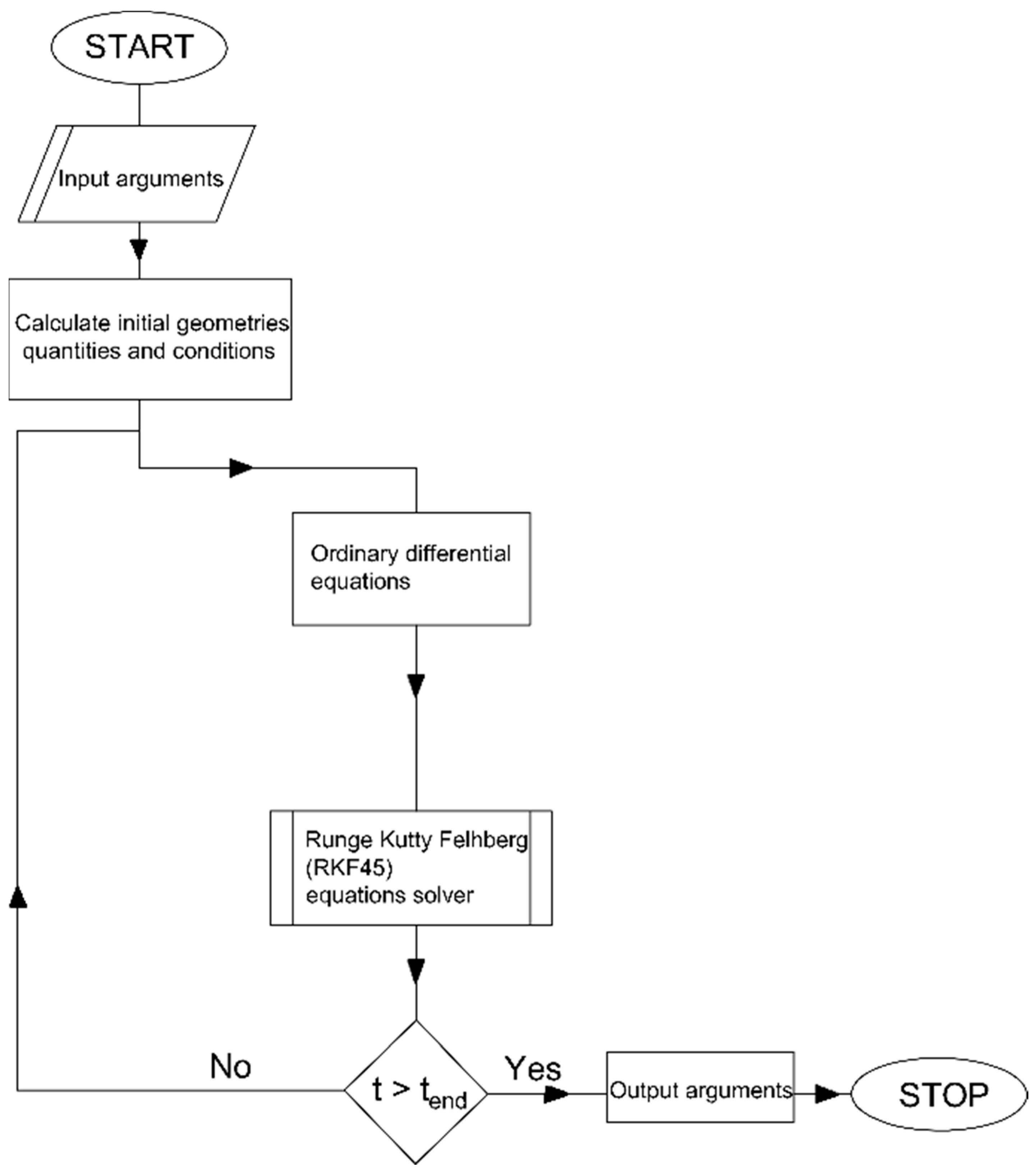
The solution procedure is presented below in Figure 2:
The initial arguments are primarily the expander system parameter, the supply pressure and the coefficients needed for calculations.
In the next step, the initial geometric quantities are calculated, e.g., the surface area of the given elements and the initial conditions, such as pressure or air mass in the tank.
Since the calculation-solving method requires high accuracy, the method presented in [20] was used. The type of calculation method has been selected with particular attention to minimise errors and maximise convergence in simulation results.

3. Results

3.1. Research Motivation

To analyse the compressed air expander, tests and computer simulations were performed in order to find the optimal solution. It was decided to investigate the influence of the selection of geometrical sizes of actuators on the efficiency, called air-to-electric efficiency by the author.

3.2. Validation

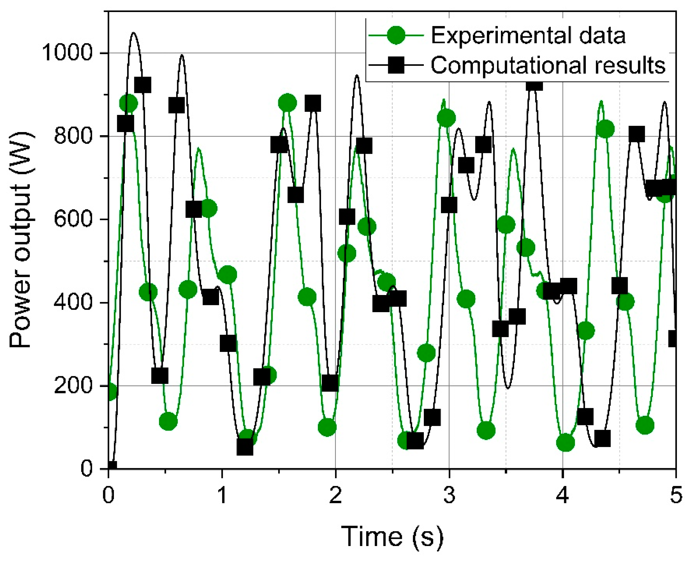
In order to confirm the correctness of the computer model, the simulation results were validated. Experimental results of single-actuator expander performance were compared. The laboratory-scale system consisted of a 200-L compressed air tank, an expander drive with a 200 mm diameter and a 200 mm stroke cylinder. The expander is connected via a mechanical gear with a permanent magnet synchronous generator. Figure 3 shows a comparison of the output power generated. Simulation results are shown on the graph as squares, and experimental results as circles.
The average power obtained from computer calculations was 493 W, and from the experimental results, 462 W. The percentage difference was only 6%. The validation showed the convergence and correctness of the model with the experimental results.

3.3. Computer Simulations

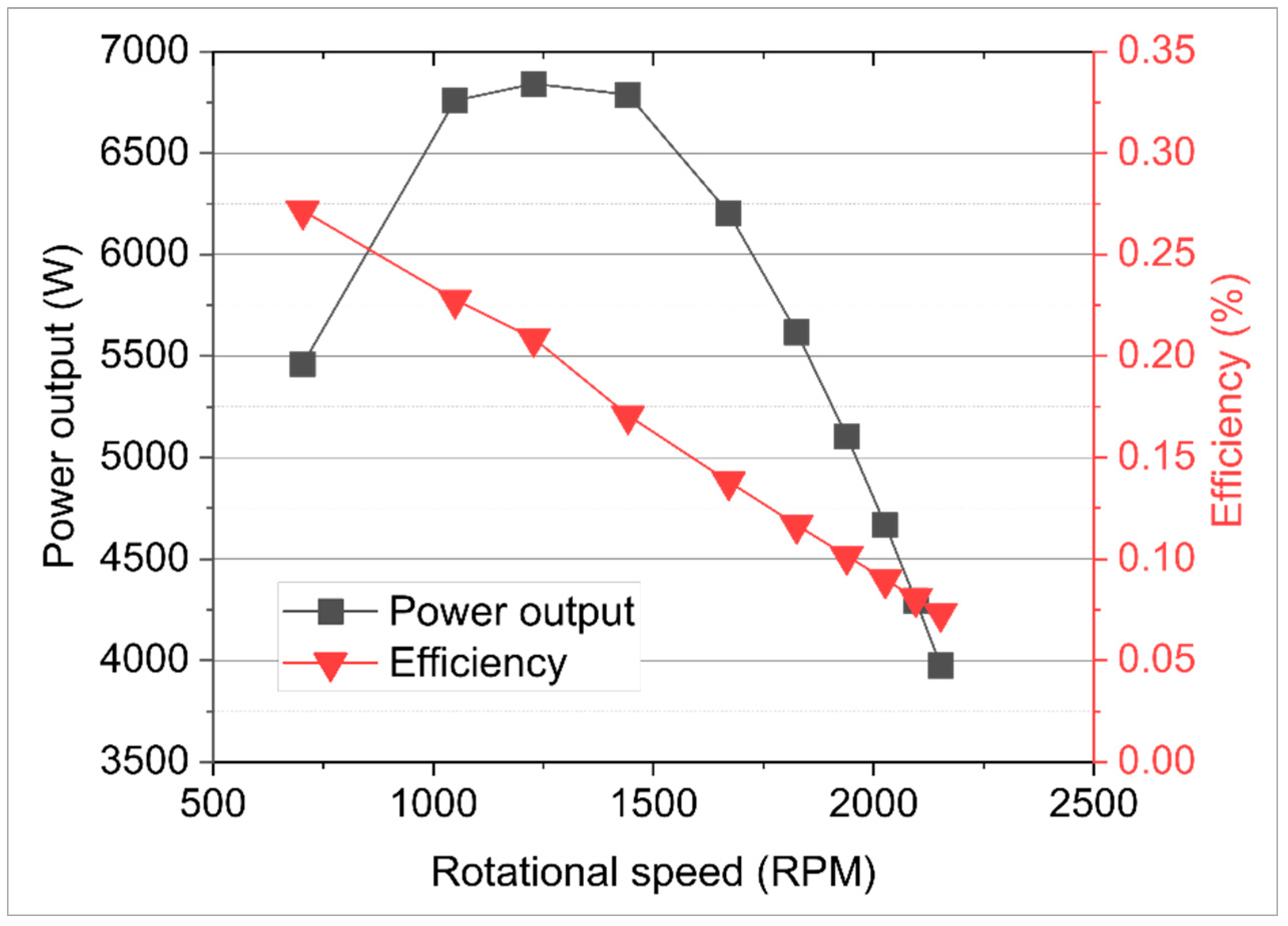
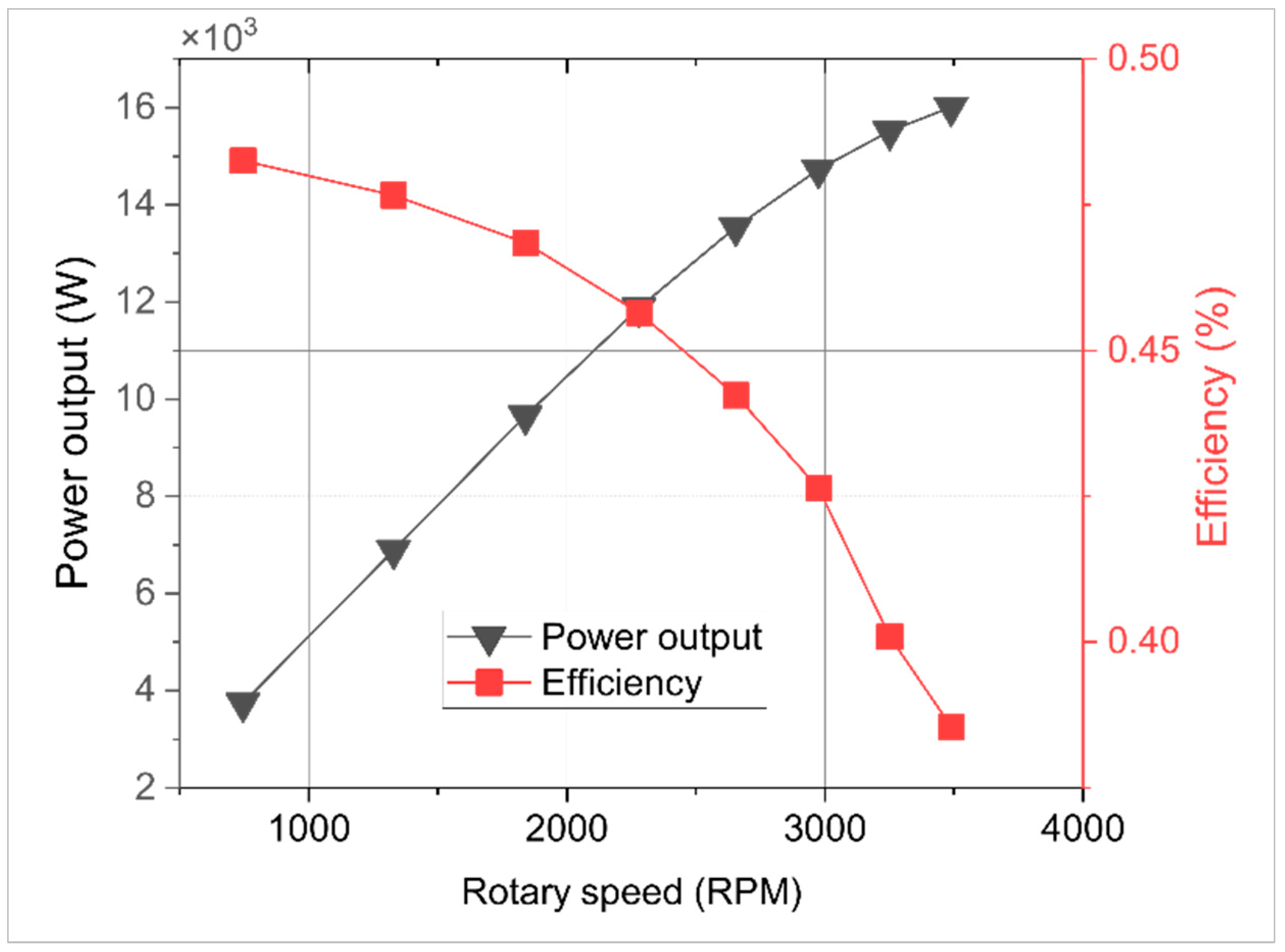
Figure 4 shows the performance of the three-cylinder expander, whose geometrical parameters are presented in Table 1. The rotational speed is controlled by a variable load resistance which takes values from 1 to 9 Ohm. The expander was working with a supply pressure of 7 bar.
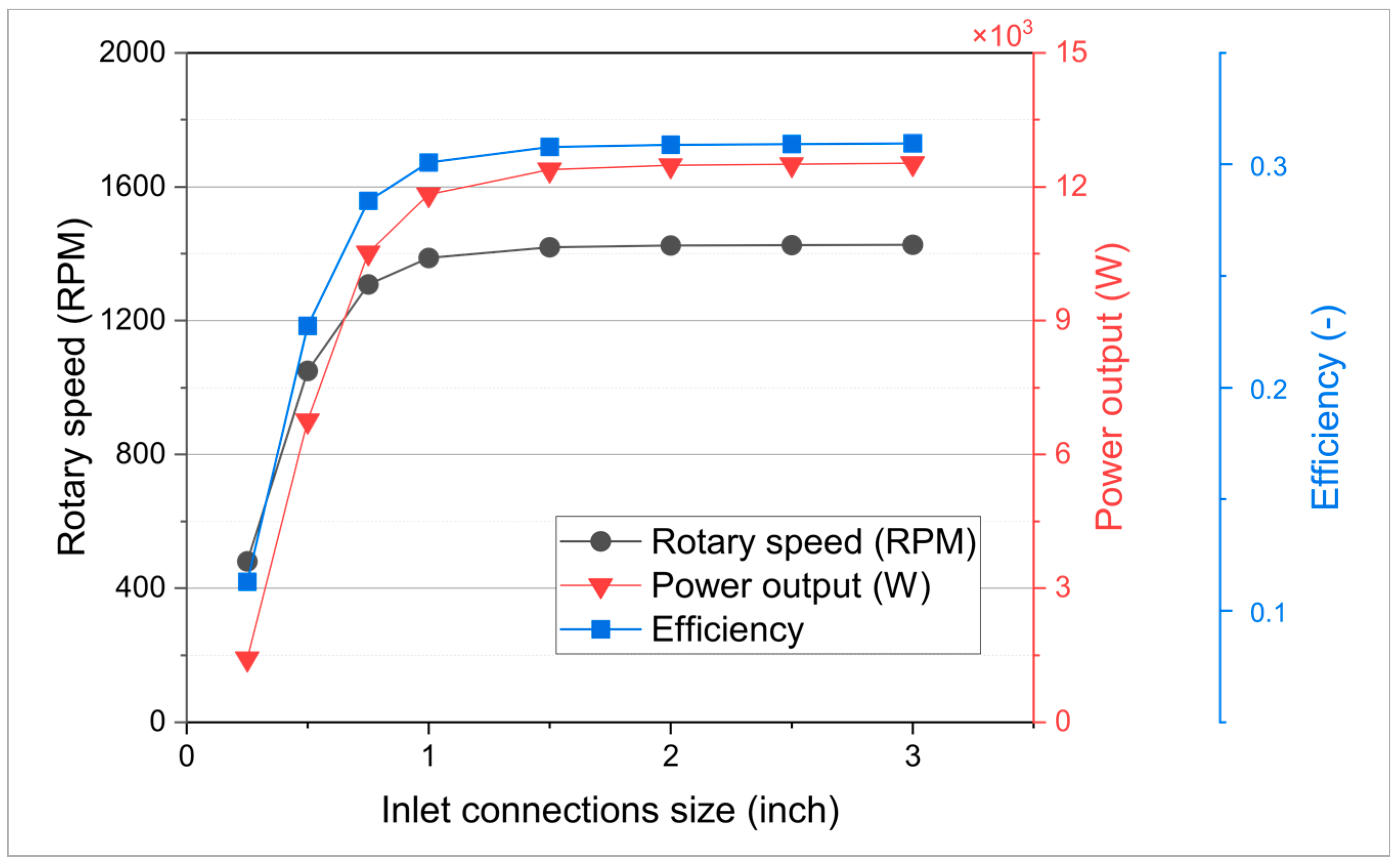
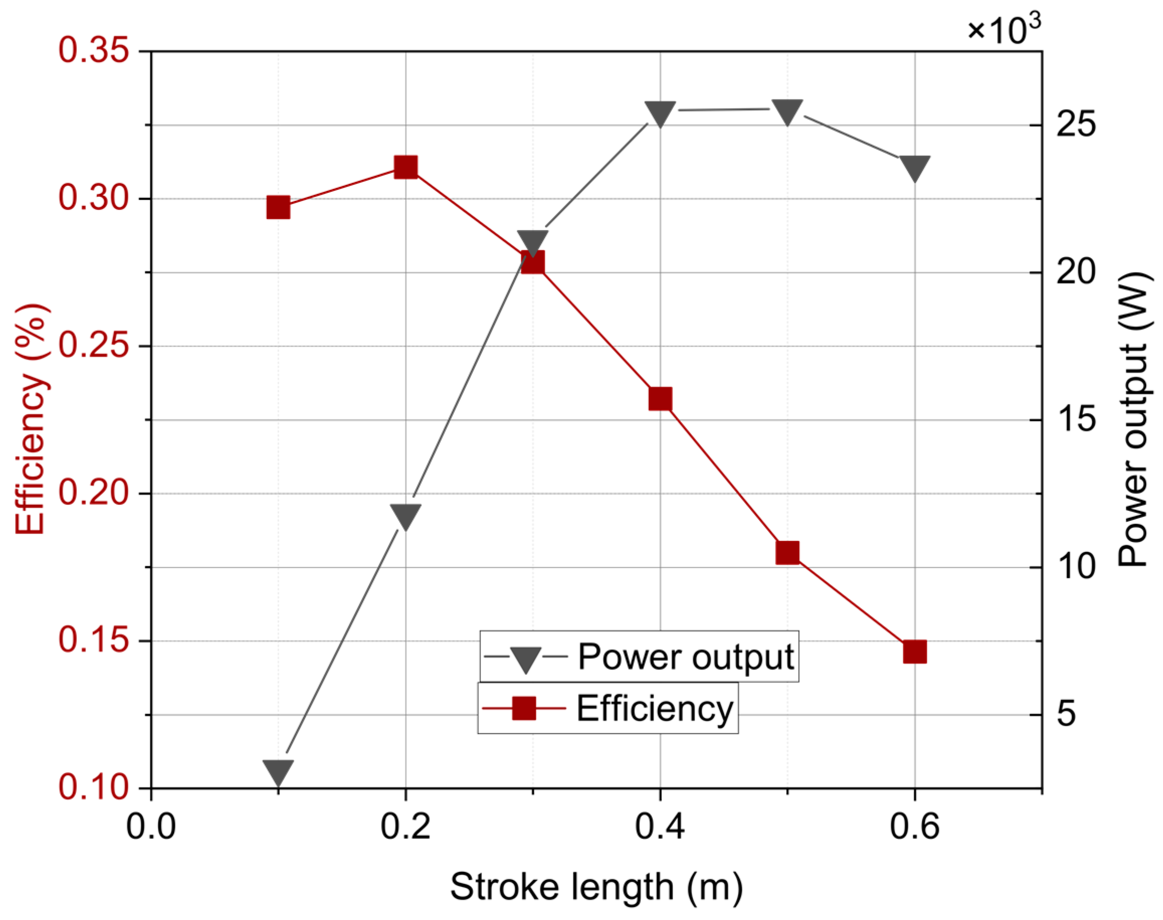
As shown in the figure, the simulations allowed us to find the optimal operating point. Depending on whether the system would ultimately work at maximum power or the highest possible efficiency, we can select the proper operating point for the desired effects. The highest efficiency of the tested three-cylinder engine was 26%, with a simultaneous generated power of 5.4 kW. To increase efficiency and improve engine operation, it was decided to perform simulations to select the appropriate connector sizes (Figure 5) and then the cylinder stroke size (Figure 6).
By choosing the right size of the cylinder inlet ports, the efficiency of the device increases by more than 5% and the output power also increases significantly.
The efficiency, power and rotational speed values increase with the size of the inlet connections. Starting from 0.25 inch in diameter up to 1 inch, we can notice a dynamic increase in the generated power. Using larger connectors up to 3 inches, we do not obtain such changes in power or efficiency values; moreover, it can be accompanied by much greater air consumption. The best solution seems to be a 1 inch connection. Therefore, optimisation simulations have been conducted for these proper values of inlet connectors.
The choice of the actuator stroke length does not increase the system’s efficiency. Still, we can obtain much higher output power with a relatively high-efficiency value and the same supply pressure. A greater stroke volume results in a larger volumetric flow of compressed air during the operation of the expander and, thus, larger air consumption. In order to obtain higher efficiency values with a larger actuator stroke, it would be necessary to find the appropriate operating point of the expander for each stroke value.
Since an efficiency of barely more than 30% does not seem to prove the usefulness of a compressed air expander, the authors decided to use the method of air injection to reduce the air supply consumption consisting in the right disconnection of the power supply at the right moment of the piston’s movement. The results of this solution are shown in the Figure 7.
The figure illustrates how the efficiency and output power curves are arranged. Since these are two different forms of energy, their relationship is not linear. The power produced by a rotating electric machine is quadratic, while the energy of air is not. Optimum efficiency and power can only be obtained if the entire expander system operates at the optimal operating point.
The study confirmed the authors’ hypothesis, which assumed that the proper selection of geometric parameters can manipulate the power and efficiency obtained by the device. Table 2 shows a comparison of the different expander types.

4. Conclusions

The study carried out confirmed the authors’ hypothesis, which assumed that the proper selection of geometric parameters can influence the obtained values of power received and device efficiency. The simulations made by the authors of the work show that we can achieve higher efficiency values by analysing individual engine components. Further research may result in even higher performance of the utilisation element and thus also higher efficiency of the entire system. Only some parameters were selected during a series of simulations. For each value of the supply pressure, target power and storage scale, a similar selection of the parameters of each element should be made to avoid rescaling, losses, and thus lower efficiency.
Using a unique compressed air injection system for the supply pressure resulted in an efficiency of more than 48%, which can be increased by selecting the appropriate parameters for this solution later. Sensitivity analysis and air injection systems significantly increase device efficiency. By using the injection system, we increase the effect of air expansion on power output, so the next development step seems to be to preheat the air in front of the expander to achieve higher efficiency. The compressed air piston engine as an element of the CAES system appears to be a good solution; however, it is still in the early stages of development. Due to their low efficiency, they are omitted and replaced with turbines. In our work, we want to draw attention to the possibilities of a compressed air reciprocating drive and how its efficiency can be increased to compete with the turbine. The work draws attention to the possible directions of development and the need to direct the attention of researchers to reciprocating expanders. A sensitivity analysis of the piston expander is the first possible optimisation step that increases efficiency. The selection of parameters is, therefore, a process that should not be omitted in any case; on the contrary, it should be given a high degree of attention. The simulations carried out show the importance of selecting the optimal parameters at the stage of construction and design of the piston expander system. The novelty of the work is to demonstrate the possibilities of using one-stroke piston expanders in CAES installation, its parameter design and control by cutting off the air supply to reduce compressed air consumption. This motivates further research, not only related to mathematical calculations and computer simulations, but also experimental research. As the literature review showed, efficiency improvement should also be sought in combined solutions, e.g., CAES with TES, PH-CAES (pumped hydro compressed air storage) or CAES with a system of isobaric tanks.

Author Contributions

Conceptualisation, J.L.; methodology J.L., D.G. and Y.S.; software, J.M. and D.G.; formal analysis, J.L., D.G., Y.S. and J.M.; resources, J.M.; writing—original draft preparation, J.M. writing—review and editing, J.L.; visualisation, J.M. All authors have read and agreed to the published version of the manuscript.

Funding

The work was carried out as part of a research subvention under contract no. 16.16.210.476 supported by the Polish Ministry of Science and Higher Education and by the Polish National Agency for Academic Exchange under the Strategic Partnerships Programme, Project No. BPI/PST/2021/1/00023.

Data Availability Statement

Not applicable.

Conflicts of Interest

The authors declare no conflict of interest.

References

  1. Bollinger, B. Demonstration of Isothermal Compressed Air Energy Storage to Support Renewable Energy Production; SustainX Smart Grid Program, Technical Raport; OSTI: Pittsburgh, PA, USA; Morgantown, WV, USA, 2015. [Google Scholar] [CrossRef]
  2. Chen, H.; Cong, T.N.; Yang, W.; Tan, C.; Li, Y.; Ding, Y. Progress in Electrical Energy Storage System: A Critical Review. Prog. Nat. Sci. 2009, 19, 291–312. [Google Scholar] [CrossRef]
  3. Mitali, J.; Dhinakaran, S.; Mohamad, A.A. Energy Storage Systems: A Review. Energy Storage Sav. 2022, 1, 166–216. [Google Scholar] [CrossRef]
  4. Maia, T.A.C.; Barros, J.E.M.; Cardoso Filho, B.J.; Porto, M.P. Experimental Performance of a Low Cost Micro-CAES Generation System. Appl. Energy 2016, 182, 358–364. [Google Scholar] [CrossRef]
  5. Tallini, A.; Vallati, A.; Cedola, L. Applications of Micro-CAES Systems: Energy and Economic Analysis. Energy Procedia 2015, 82, 797–804. [Google Scholar] [CrossRef] [Green Version]
  6. He, W.; Luo, X.; Evans, D.; Busby, J.; Garvey, S.; Parkes, D.; Wang, J. Exergy Storage of Compressed Air in Cavern and Cavern Volume Estimation of the Large-Scale Compressed Air Energy Storage System. Appl. Energy 2017, 208, 745–757. [Google Scholar] [CrossRef]
  7. Shengwei, M.; Wang, J.; Fang, T.; Laijun, C.; Xiaodai, X.; Qiang, L.U.; Yuan, Z.; Zhou, X. Science China Design and Engineering Implementation of Non-Supplementary Fired Compressed Air Energy Storage System: TICC-500. Sci. China Tech. Sci. 2015, 58, 600–611. [Google Scholar] [CrossRef]
  8. Technology—Hydrostor. Available online: https://www.hydrostor.ca/technology/ (accessed on 19 November 2022).
  9. Camargos, T.P.L.; Pottie, D.L.F.; Ferreira, R.A.M.; Maia, T.A.C.; Porto, M.P. Experimental Study of a PH-CAES System: Proof of Concept. Energy 2018, 165, 630–638. [Google Scholar] [CrossRef]
  10. Barbour, E.R.; Pottie, D.L.; Eames, P. Why Is Adiabatic Compressed Air Energy Storage yet to Become a Viable Energy Storage Option? iScience 2021, 24, 1–26. [Google Scholar] [CrossRef] [PubMed]
  11. Mazloum, Y.; Sayah, H.; Nemer, M. Exergy Analysis and Exergoeconomic Optimization of a Constant-Pressure Adiabatic Compressed Air Energy Storage System. J. Energy Storage 2017, 14, 192–202. [Google Scholar] [CrossRef]
  12. Tong, Z.; Wang, H.; Xiong, W.; Ting, D.S.; Carriveau, R.; Wang, Z. Accumulated and Transient Exergy Analyses of Pneumatic Systems with Isochoric and Isobaric Compressed Air Storage Tanks. Energy Storage 2021, 3, 1–10. [Google Scholar] [CrossRef]
  13. Mazloum, Y.; Sayah, H.; Nemer, M. Dynamic Modeling and Simulation of an Isobaric Adiabatic Compressed Air Energy Storage (IA-CAES) System. J. Energy Storage 2017, 11, 178–190. [Google Scholar] [CrossRef]
  14. Wang, H.; Tong, Z.; Dong, X.; Xiong, W.; Ting, D.S.K.; Carriveau, R.; Wang, Z. Design and Energy Saving Analysis of a Novel Isobaric Compressed Air Storage Device in Pneumatic Systems. J. Energy Storage 2021, 38, 102614. [Google Scholar] [CrossRef]
  15. Budt, M.; Wolf, D.; Span, R.; Yan, J. A Review on Compressed Air Energy Storage: Basic Principles, Past Milestones and Recent Developments. Appl. Energy 2016, 170, 250–268. [Google Scholar] [CrossRef]
  16. Qing, S.; Wang, Y.; Wen, X.; Zhong, J.; Gou, X.; Tang, S. Optimal Working-Parameter Analysis of an Ejector Integrated into the Energy-Release Stage of a Thermal-Storage Compressed Air Energy Storage System under Constant-Pressure Operation: A Case Study. Energy Convers Manag. 2021, 247, 114715. [Google Scholar] [CrossRef]
  17. He, W.; Wang, J. Optimal Selection of Air Expansion Machine in Compressed Air Energy Storage: A Review. Renew. Sustain. Energy Rev. 2018, 87, 77–95. [Google Scholar] [CrossRef]
  18. Leszczyński, J.S.; Gryboś, D. Compensation for the Complexity and Over-Scaling in Industrial Pneumatic Systems by the Accumulation and Reuse of Exhaust Air. Appl. Energy 2019, 239, 1130–1141. [Google Scholar] [CrossRef]
  19. Cai, M.; Kagawa, T.; Kawashima, K. Energy Conversion Mechanics and Power Evaluation of Compressible Fluid in Pneumatic Actuator Systems. In Proceedings of the 37th Intersociety Energy Conversion Engineering Conference (IECEC) 2002, Washington, DC, USA, 29–31 July 2002; pp. 471–474. [Google Scholar]
  20. Mohd Nor, M.A.; Suwa, Y. Evaluation of the Accuracy of Trajectory Time Integration Used for Lagrangian Particle Tracking. Earozoru Kenkyu 2022, 37, 127–135. [Google Scholar] [CrossRef]
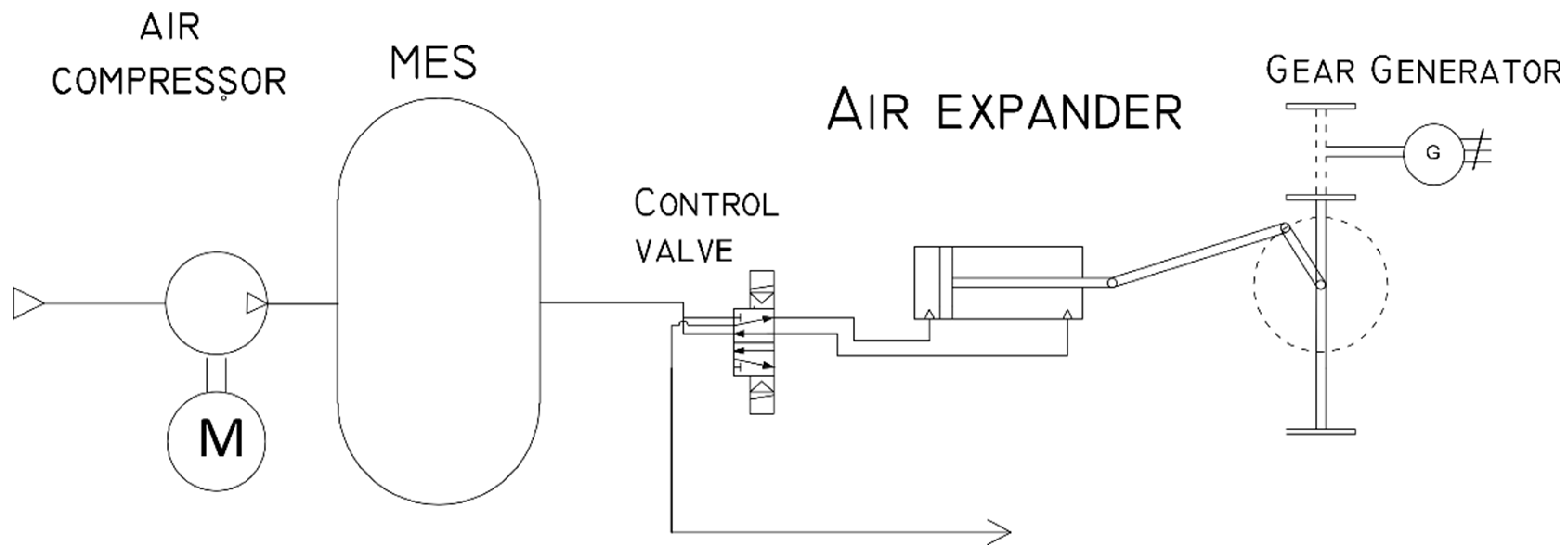
Figure 1. Conceptual diagram of the CAES system.
Energies 16 02310 g001
Figure 2. Flowchart of a set of ordinary differential equations solver.
Energies 16 02310 g002
Figure 3. Comparison of power output—experimental data and computational results.
Energies 16 02310 g003
Figure 4. Efficiency and power output as a function of the rotary speed for the three-cylinder engine.
Energies 16 02310 g004
Figure 5. Efficiency and power output as a function of the inlet connections for the three-cylinder engine.
Energies 16 02310 g005
Figure 6. Efficiency and power output as a function of stroke length for a three-cylinder engine.
Energies 16 02310 g006
Figure 7. Efficiency and power output as a function of the rotary speed for the three-cylinder engine with special air injection system and a supply pressure of 7 bar.
Energies 16 02310 g007
Table 1. Initial parameters of simulated CAS.
ParameterValueUnit
Cylinder Stroke0.2m
Cylinder diameter0.1m
Crank length0.1m
Crank arm length0.42m
Supply pressure7bar
Inlet ports size0.5inch
Temperature of stored air293K
R L O A D From 1 to 9Ohm
R g 0.13Ohm
N p b 6-
L g 0.26 mH
Ψ 0.08Wb
Table 2. Comparison of different expander prototypes.
ExpanderEfficiency [%]
One Cylinder engine19
Three-cylinders engine32
Three-cylinder engine with air injection system48
Disclaimer/Publisher’s Note: The statements, opinions and data contained in all publications are solely those of the individual author(s) and contributor(s) and not of MDPI and/or the editor(s). MDPI and/or the editor(s) disclaim responsibility for any injury to people or property resulting from any ideas, methods, instructions or products referred to in the content.