Article

Multi-Objective Optimization of Graded Thermal Storage System for Direct Steam Generation with Dish Concentrators

School of Mechanical Engineering, Beijing Institute of Petrochemical Technology, Beijing 102617, China
*
Author to whom correspondence should be addressed.
Energies 2023, 16(5), 2404; https://doi.org/10.3390/en16052404
Submission received: 1 February 2023 / Revised: 21 February 2023 / Accepted: 28 February 2023 / Published: 2 March 2023
(This article belongs to the Special Issue Advances in Geothermal and Solar Energy Development and Utilization)

Abstract

:
A single sensible thermal storage system has the disadvantage of poor system efficiency, and a sensible-latent graded thermal storage system can effectively solve this problem. Moreover, the graded thermal storage system has the virtue of being adjustable, which can be adapted to many power generation systems. Therefore, this paper first analyzes the influence factors of the graded thermal storage system’s exergy and thermal efficiency. Subsequently, each factor’s significance was analyzed using the response surface method, and the prediction model for system exergy efficiency and cost was established using the support vector machine method. Finally, the second-generation nondominated sorting genetic algorithm (NSGA-II) was used to globally optimize the graded thermal storage system’s exergy efficiency and cost by Matlab software. As a result, the exergy efficiency was increased by 11.01%, and the cost was reduced by RMB 5.85 million. In general, the effect of multi-objective optimization is obvious.

1. Introduction

Concentrated solar power with thermal energy storage (TES) is an essential solar thermal power (STP) technology. When the sunlight is insufficient or the power grid needs peak shaving, the stored thermal energy is converted to electric energy to meet the demand for a stable power supply [1,2,3]. Therefore, STP is a promising generation technology for renewable energy. Sunlight is concentrated on the heat absorber through the parabolic reflector, and the working medium is heated. Then, the high pressure and temperature steam is generated to drive the turbine to achieve electric energy. STP technology can be divided into four types: tower, dish, trough, and linear Fresnel [4,5,6]. Compared with the other three forms, the dish-type STP has a simple structure, flexible layout, higher power generation efficiency, and great potential for cost reduction [7]. In addition, different positions and different energies of solar energy have minimal impact on the dish-type STP. Currently, research on the dish-type STP is mainly focused on solar Stirling power generation. However, this type of power generation system cannot store heat and does not have the capability of stable and continuous power output, so it cannot be applied to commercial applications. Therefore, research on dish-type STP with TES is urgently needed.
According to the heat storage principle, TES technologies include thermochemical heat storage and thermophysical heat storage (sensible and latent TES) [8]. The thermochemical TES has a much higher energy density than the thermophysical TES. Sensible TES has the advantages of low cost, simple principles, convenient management, etc., and is widely used in the STP field. The benefits of latent TES are high TES density, relatively small heat storage volume, and slight temperature fluctuation [9,10,11]. In the dish-type STP, water as the heat transfer medium has the characteristics of no pollution, no corrosion, and low price. At the same time, direct steam generation technology is mature and has good application prospects [12,13,14]. However, the water-working medium undergoes a phase change, and it is difficult for a single sensible TES to match the temperature–enthalpy curve of the water-working medium, resulting in a large energy loss. The graded TES, which couples sensible and latent TES, can solve this problem. The graded TES has a broader range of adjustable parameters and can be adapted to various power generation systems compared with the single-stage TES. However, minimal research on graded TES restricts its development and application to some degree.
Among the graded TES, the sensible-latent graded TES is mostly studied. In 2009, Laing et al. [15] first proposed a solid concrete three-tank graded sensible-latent graded TES. The material’s melting point shows that the phase change material (PCM) uses sodium nitrate (NaNO3). To study the process of heat storage/release for the graded TES, the German Aerospace Center [16] has built a sensible-latent graded TES for the Spanish direct steam power generation system. To improve the PCM’s thermal conductivity, Laing et al. [15] used a PCM system containing aluminum fins and tested this system for 172 cycles at 400 ℃/11.0 MPa. The results showed that the PCM would not degrade and had a reasonable heat storage/heat release rate. This experimental system’s successful implementation guaranteed the later experiments’ safety. Additionally, it confirmed the feasibility of applying sensible-latent graded TES in direct steam solar thermal power generation.
Birnbaum et al. [17] studied the direct steam generation power system based on Spain’s 50 MW installed capacity power station. It was found that the temperature of the reheated steam was significantly lower than that of the main steam. Guo et al. [18] proposed a three-tank graded TES, in which a sensible TES consists of two-tank indirect TES and two heat exchangers. An intermediate buffer tank is added, and the mass flow rate of liquid sensible heat storage material could be adjusted according to the temperature–enthalpy characteristic curve of hydraulic characteristics so that the temperature–enthalpy characteristic curve of heat storage material could be better matched with water-based working medium and the system efficiency is improved. Guo et al. [19] compared the exergy efficiency and thermal efficiency of the two-tank sensible, three-tank sensible, and two-tank sensible-latent graded TES based on the previous three-stage graded TES through thermodynamic calculation. The results showed that the temperature–enthalpy characteristic curve of double-tank sensible TES is well matched with the water-based working medium, which effectively solved the problem of excessive loss caused by the pinch analysis. The exergy efficiency and thermal efficiency were about twice that of the single-stage sensible TES. Based on the above studies, Bian et al. [20] studied the energy level matching of sensible-latent graded TES and adopted a single objective optimization method to optimize the system’s exergy efficiency. After optimization, the exergy efficiency of the graded TES increased by 20%.
Due to the internal complexity of the sensible-latent graded TES, the experimental method has some limitations, such as low efficiency, long time consumption, and a large investment. The thermodynamic calculation method can solve this problem. However, thermodynamic calculation of a sensible-latent graded TES is still time-consuming, and the data-driven surrogate models can effectively solve this problem. The artificial neural network (ANN) [21] and support vector machine (SVM) [22] are widely used surrogate models. Compared with the traditional ANNs, the SVM has good generalization ability and can obtain the optimal solution with fewer samples. This method is an intelligent algorithm proposed in 1995 by Cortes and Vapnik. Due to this study’s small number of sample points, SVM was chosen to establish the surrogate model.
The sensible-latent graded TES generally considers the two factors of exergy efficiency and cost. While ensuring high exergy efficiency, the cost is also low, resulting in better overall system performance. With the development of computer science, optimization algorithms are more and more widely used in system optimization [23]. Based on the first nondominated sorting genetic algorithm (NSGA), NSGA-II [24] studied the fast non-dominated sorting method and crowded comparison operator. Therefore, this algorithm has good global search performance and is the most popular multi-objective optimization algorithm [25]. Rahder et al. [26] applied the NSGA-II method in the optimization of ice thermal energy storage air conditioning system, and the results showed that energy consumption and annual carbon dioxide emissions were reduced by 11% after optimization. Yuan et al. [27] improved the performance of household air conditioners based on NSGA-II method, saving 20–26% of energy after optimization and about $1.8–3.4 in cost. Li et al. [28] studied the optimization of dish-shaped Brayton system based on NSGA-II method and finally got the optimal solution. However, it was found that there needs to be research on the optimization design of the dish-type graded TES.
In summary, the energy level match for the dish-type sensible-latent graded TES is relatively low. Thus, the system may have low exergy efficiency and high cost. There needs to be more research on the performance optimization design of the dish-type STP. Therefore, this paper intends to study the system’s heat storage and release performance by analyzing the effects of different factors on the exergy efficiency of the system. BBD experimental design and response surface methodology were used to analyze the significance of various factors on the cost of graded TES. The prediction model for the exergy efficiency and cost of the sensible-latent graded TES was established using the SVM. The NSGA-II algorithm globally optimizes the graded TES to realize the optimal parameter configuration for the exergy efficiency and cost.

2. System and Method

2.1. System Introduction

Figure 1 illustrates the working process of the dish-type direct steam generation STP system with TES [29,30,31]. The low-temperature water absorbs the concentrated solar energy in the absorber and turns it into high-temperature and high-pressure steam. Then, the steam drives the turbine to generate electricity and stores/releases energy according to the load. The amount of superheated steam generated by the heat absorber during the daytime operation is far greater than the steam amount required by the system. The excess superheated steam heat is stored in the TES material. When the heat absorber cannot work, it serves as the heat source to supply the system to run normally.
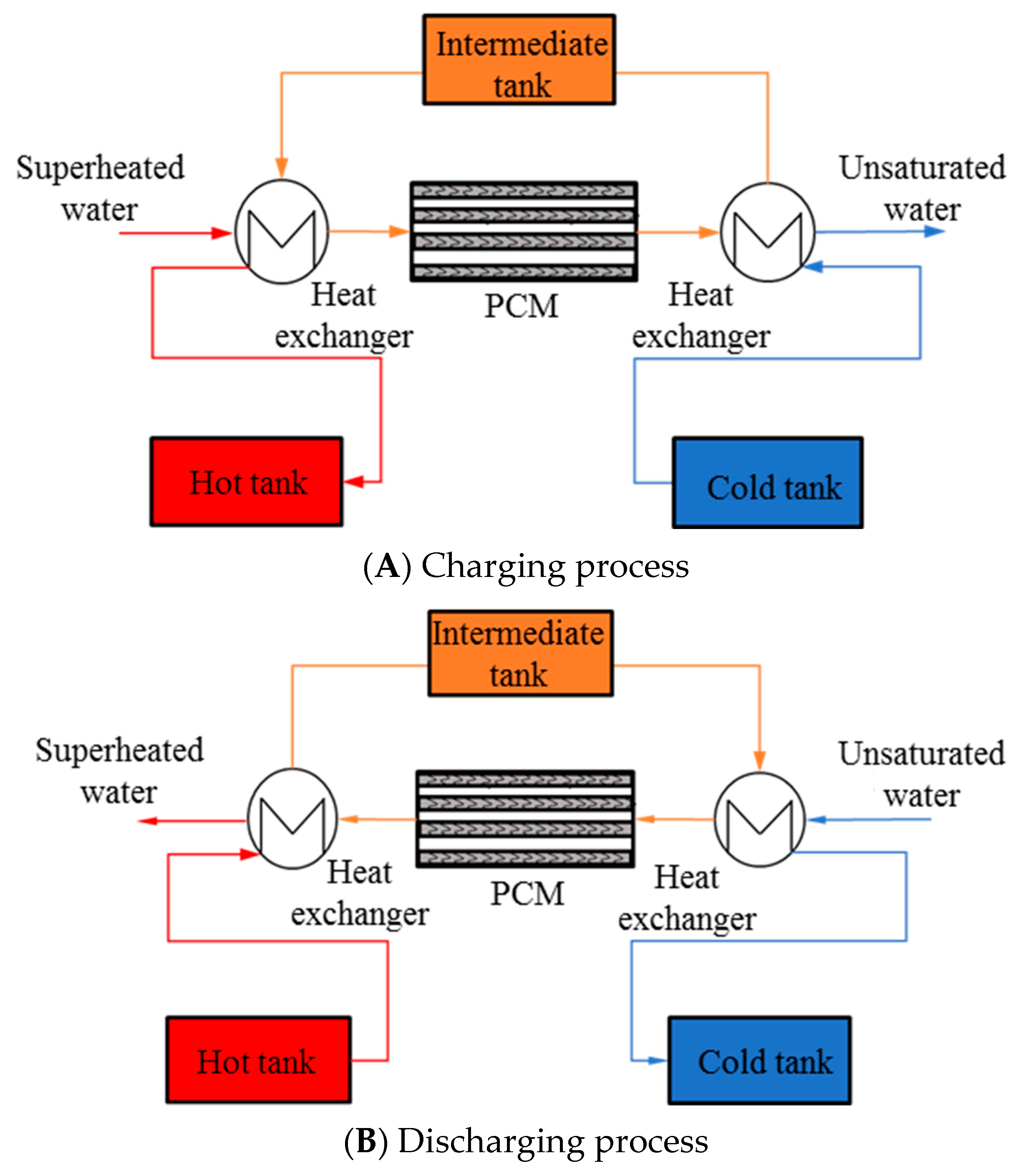
Using a two-tank sensible-latent graded TES can effectively solve the difficulty of a single-stage TES by matching the temperature–enthalpy characteristic curve of the working fluid [32,33,34]. However, the temperature–enthalpy characteristic curve of the working fluid in this system cannot have the same slope for the sensible heat section. The reason is that the specific heat capacity of the superheated steam and liquid water varies greatly. Therefore, an intermediate tank is added between the high-temperature and low-temperature heat exchangers to solve this problem. Figure 2 shows the sensible-latent graded TES sketch map with an intermediate tank.

2.2. Theoretical Method of the TES System

The power generation system is a 25 kW dish-type direct steam thermal power generation system. The power generation is in the form of a steam turbine driving a generator to generate electricity. The heat storage time is the operating hours of the steam turbine at night. According to the energy balance, the heat required for normal operation of the turbine during the TES period is called the TES capacity of the TES system. The formula of the heat required for normal operation of the turbo-generator is as follows:
Q 0 = 3600 · P e · t η e
where Q0 is the heat required by the turbo-generator, kJ; Pe is the installed capacity of the power station, kW; t is the TES time, h; and ηe is the absolute electrical efficiency of the turbo-generator.
Heat loss will occur during the operation of the TES system, resulting in insufficient utilization of the stored heat. Therefore, the heat loss of these parts must be considered when calculating the mass of the TES material. The formula for the mass of the TES material in the system is as follows:
m = Q 1 c p Δ t = Q 0 η 2 c p Δ t = 3600 P e t η e η 2 c p Δ t
where Q 1 is the total amount of TES, kJ; cp is the specific heat capacity of the working fluid, kJ/kg·°C; Δ t is the TES temperature difference of the TES material, °C; η2 is the thermal efficiency of the TES system, since the thermal efficiency of the TES system is unknown when calculating the mass of the TES material, it is necessary to perform a certain number of iterations until the equation reaches equilibrium to obtain the total mass of the TES material.
During the process of heat storage and release, the calculation formula for the temperature enthalpy characteristic curve of the system is as follows:
Q = m c p Δ T
where Q is the heat change, kJ; m is the mass flow rate of the working fluid, kg/s; c p is the specific heat capacity of the working fluid, kJ/kg·°C; and ΔT is the temperature difference of the working fluid at different positions, °C.
The exergy analysis method was used to compare and evaluate the thermodynamic performance of the graded TES system [35].
E x = Δ H T e Δ S
where Ex is exergy, kJ; ΔH is the enthalpy change of the working fluid in the TES or heat release process, kJ; Te is the ambient temperature, °C; and ΔS is the entropy change caused by the heat exchange process, kJ/kg·°C [36,37].
The formula for the entropy change is as follows:
Δ S = m h c p , h ln ( T h , o T h , i ) + m c c p , c ln ( T c , o T c , i )
where h and c respectively represent the hot- and cold-working fluids, and i and o denote the inlet and outlet.
The exergy efficiency (REx) of TES system was obtained by substituting REx from Equations (2)–(4) into the following equation.
R E x = E x D E x C
The effectiveness for high-temperature heat exchangers can be written as [38]:
ε = 1 exp [ N t u H ( 1 ( m c p ) min / ( m c p ) max ) ] 1 ( ( m c p ) min / ( m c p ) max ) exp [ N t u H ( 1 ( m c p ) min / ( m c p ) max ) ]
where NtuH is the number of heat transfer units of high-temperature heat exchanger. The outlet temperatures of liquid LBE and superheated steam in high-temperature heat exchanger can be derived from the entry condition and Equation (7).

2.3. Economic Calculation Method for TES System

The cost of the TES system is composed of direct and indirect costs. The direct cost comprises TES material cost, TES tank cost, and miscellaneous cost, and the indirect cost includes tax and engineering cost. Because the research is mainly based on theoretical analysis, only direct costs are considered when calculating the cost of the TES system.

2.3.1. Calculation of TES Tank Parameters

The TES tank is an essential component of the TES system. According to the calculation results of Formula (2), the volume of the TES material is calculated. The calculation formula is as follows:
V 1 = m ρ
When calculating the internal volume of the tank, for practical safety considerations, the volume of the TES tank is calculated as 1.15 times the volume of the TES material.
V = 1.15 × V 1
After the calculation result of the Formula (2) is determined, the internal diameter of the tank can be calculated. The calculation method is as follows:
d = 4 V n π 3
where n is the ratio of the tank’s inner diameter and height. In this paper, this ratio is 3.

2.3.2. Cost Calculation of the TES System

The calculation formula for the cost of TES material is:
C s m = C s m * M s m × 10 3
where Csm is the cost of TES material; C s m * is the unit price of the TES material; and Msm is the total mass of the TES material, kg.
The calculation formula for the cost of a single TES tank is:
C s t = C s t * ρ s t ( V tan k 1.15 M s m ρ s m ) × 10 3
where C s t is the cost of a single TES tank, RMB; C s t * is the unit price of tank steel, yuan/t; ρ s t and ρ s m are the density of the steel material and the density of the heat storage material in kg/m3; Vtank is the total volume of the TES tank.
The unit prices of different materials in the calculation of the TES system cost are shown in Table 1.

2.4. Optimization Design Analysis Method

2.4.1. Response Surface Method

When analyzing the significance of factors using the response surface method, the commonly used sample design methods include the central composite design (CCD) and the Box–Behnken design (BBD) [39,40]. Compared with the CCD test, the overall number of test combinations in the BBD test is smaller and thus has higher economic efficiency. Therefore, this paper selects the BBD experimental design for the optimization study and Design Expert 11 was used to design the structural parameter scheme of the graded TES. The BBD method was used to obtain the structural parameter design scheme of the 17-component TES system. The specific structural design parameters are shown in Table 2. The above test scheme was calculated using the thermodynamic and economic calculation program of the graded TES system.

2.4.2. Data-Driven Surrogate Model

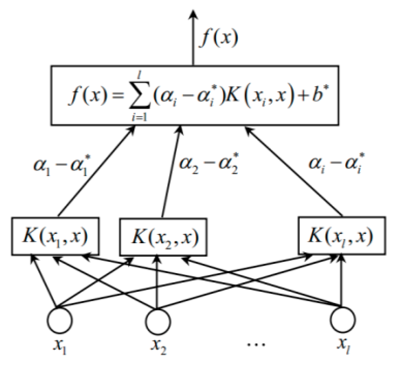
In multi-objective optimization, the physical model has the disadvantages of long computing time and low computing efficiency. Thus, a data-driven surrogate model is established using the SVM [41]. As a fast and efficient forecasting tool, SVM can predict the REx and cost of graded TES efficiently and quickly. The surrogate model via the SVM can be expressed as follows:
f ( x ) = x i S V M α i α i * K x i x + b
where α i , α i * is the Lagrange multipliers; b is the undetermined coefficient vector; K ( x i x ) = ϕ ( x i ) ϕ ( x j ) is the kernel function.
The surrogate model is implemented using the open-source MATLAB library LIBSVM. LIBSVM provides the linear, polynomial, radial basis (RBF), sigmoid, and precomputed kernel functions. By comparing the adaptability, the present work uses the RBF kernel function. The expression is as follows:
K ( x i , x j ) = exp ( x i x j 2 / 2 γ 2 )
Figure 3 shows the structure diagram of SVM. Each support vector can be represented by an intermediate node, and the linear combination of the intermediate nodes can obtain the output.
Therefore, this study firstly determines the constraint conditions for the optimal design of a graded TES according to the pitch point constraint conditions and uses the BBD experimental design method to obtain the sample solution set required for prediction. Secondly, thermodynamics is applied to calculate the REx and total system cost of each design sample to obtain a rapid prediction model of the system.

2.4.3. Multi-Objective Optimization Method

The multi-objective problem usually has multiple objectives, which are mutually exclusive. If one of them increases, the other one decreases. Therefore, multi-objective optimization is not the optimal global solution but a series of optimal solution sets. The goal of multi-objective optimization is to find the Pareto optimal solution set for a specific optimization problem. Figure 4 illustrates the principle of the NSGA-II algorithm. More details about the NSGA-II algorithm are provided elsewhere.
Figure 5 illustrates the optimization flow chart of the NSGA-II algorithm. The fitness functions (i.e., cost parameter and REx) are evaluated via SVM using the data-driven surrogate model. The parameter settings are shown in Table 3.

3. Results and Discussion

3.1. Analysis of Influencing Factors

In this section, the control variable method is adopted. Different parameters are studied by thermodynamic calculation, including the mass flow rate of the TES material from the cold tank to the intermediate tank (ms), the superheated steam temperature at the inlet of the system (Ts), and the ratio of the mass flow rate of the regenerative material from the cold tank to the intermediate tank to the thermal material from the intermediate tank to the hot tank (Rm). The calculation case parameters are shown in Table 4.

3.1.1. The Effect of ms of TES Material on the Graded TES

The TS and Rm were fixed to study the effect of ms on the graded TES. The TES conditions with ms of 18 kg/s, 19 kg/s, 20 kg/s, 21 kg/s, and 22 kg/s were studied. To prevent the sensible TES material from solidifying during the heat storage and release process, the temperature of the sensible TES material in the fixed cold tank is 227 °C. At the same time, the temperature of the working fluid at the outlet was set to 247 °C.
Figure 6 shows the variation in the sensible heat of the superheated steam absorbed by the sensible TES material and the latent TES material with the steam at the system’s inlet during the TES process of the graded TES system. It can be seen from the figure that as the ms of the TES material in the system increases, the sensible heat storage material absorbs heat in the superheated steam section under heat storage condition (QCS) and the superheated steam section gradually increases, but the latent heat storage material in the superheated steam section absorbs heat under heat storage conditions (QCN) and gradually decreases. As the ms of the TES material increases, the temperature of the system hot tank first decreases and then increases. The reason is that when the ms of the TES material is changed, the heat capacity flow (the product of the ms and the specific heat capacity) between the TES material and the working fluid changes, which causes the heat exchanger performance to change significantly, which affects the outlet temperature of TES material of the heat exchanger and the outlet temperature of hot material. Other factors need to be analyzed to obtain the change of the different ms of the sensible TES material on the TES and release performance of the system.
Figure 7 shows the variation pattern of the energy level in the high-temperature and low-temperature heat exchangers with the ms of the TES material during the heat release process. For the energy level heat QDL in the low-temperature heat exchanger, the ms of the sensible TES material was increased from 18 kg/s to 22 kg/s, and QDL increased from 2.4 MW to 2.7 MW. At the same time, the energy level QDH in the high-temperature heat exchanger rapidly increased from 1.6 MW to 2.0 MW. The figure shows that when the ms of the working fluid increases from 20 kg/s to 21 kg/s, the energy level heat QDL of the high-temperature heat exchanger suddenly increases. The primary cause is that the efficiency of the heat exchanger is significantly improved, which increases the heat transfer temperature difference, increasing the energy level of the high-temperature heat exchanger.
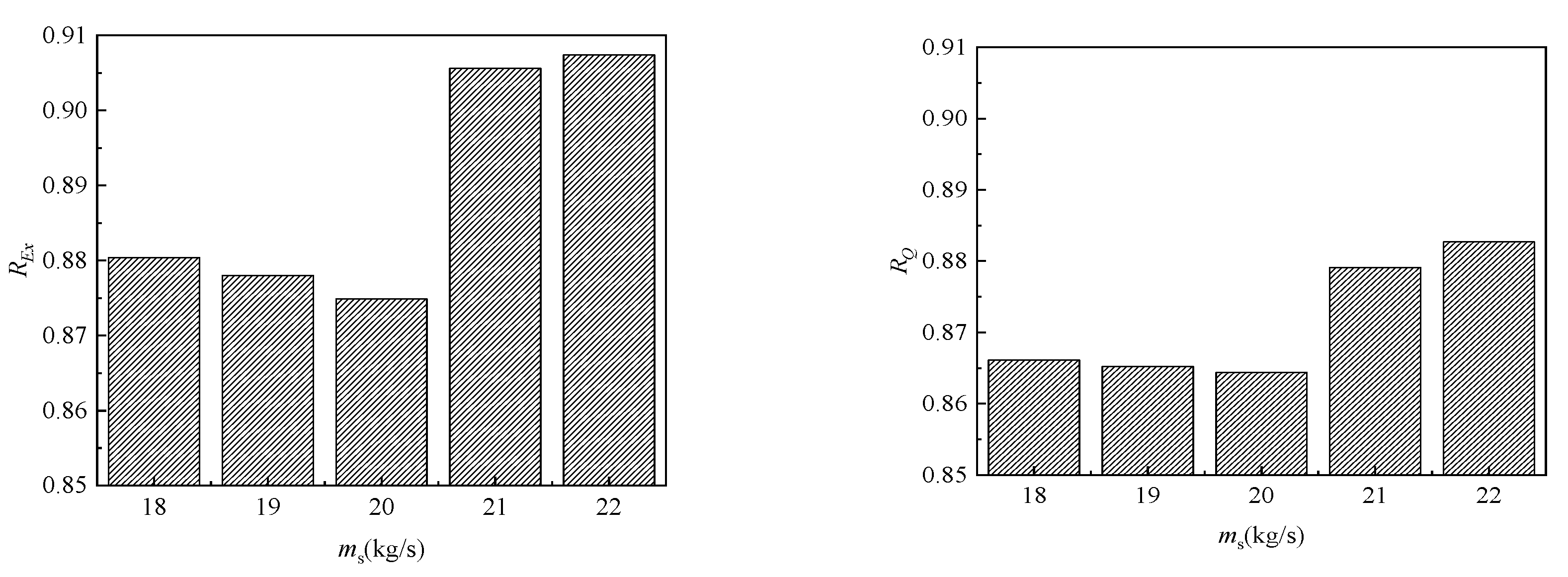
Based on the variation pattern of the energy level heat in the high-temperature and low-temperature heat exchangers with the ms, the storage and release performance of the system is further studied. As shown in Figure 8, when the ms of the TES material increases, the exergy efficiency of the system REx and the thermal efficiency of the system RQ of the system both decrease. As the ms of the TES material increased from 18 kg/s to 20 kg/s, the REx and RQ of the system decreased to 87.49% and 86.44%, respectively. As the ms of the TES material increases from 20 kg/s to 21 kg/s, the change in efficiency reduces the energy level of the low-temperature heat exchanger during the process of heat release. It simultaneously increases the energy level of the high-temperature heat exchanger, which eventually leads to the REx of the system’s significant increase.

3.1.2. Effect of TS on the Graded TES System

When studying the effect of system inlet steam on the graded TES system, the fixed variable method was also used to study the working conditions of the TS of 450 °C, 500 °C, 550 °C, 600 °C, and 650 °C.
Figure 9 shows the curve of sensible heat absorbed by superheated steam in the heat storage process in the graded TES. It can be seen from the figure that as the temperature of the superheated steam at the inlet of the system increases, the QCS and QCN of the superheated steam section gradually increase. Moreover, with the increase in superheated steam temperature, the growth rate of QCS is greater than the growth rate of QCN. Since the amount of heat used to absorb the latent heat of the working fluid in the latent TES energy level remains unchanged, it can be concluded that when the temperature of the superheated steam at the inlet of the system is changed, the heat increase of the energy level of the high-temperature heat exchanger is much larger than that of the phase change TES energy level, considering that the energy level matching of TES materials under TES conditions is not sufficient to explain the effect of energy level matching on the overall TES and release performance of the graded TES system. Therefore, it is necessary to study the energy level matching in the exothermic process systematically.
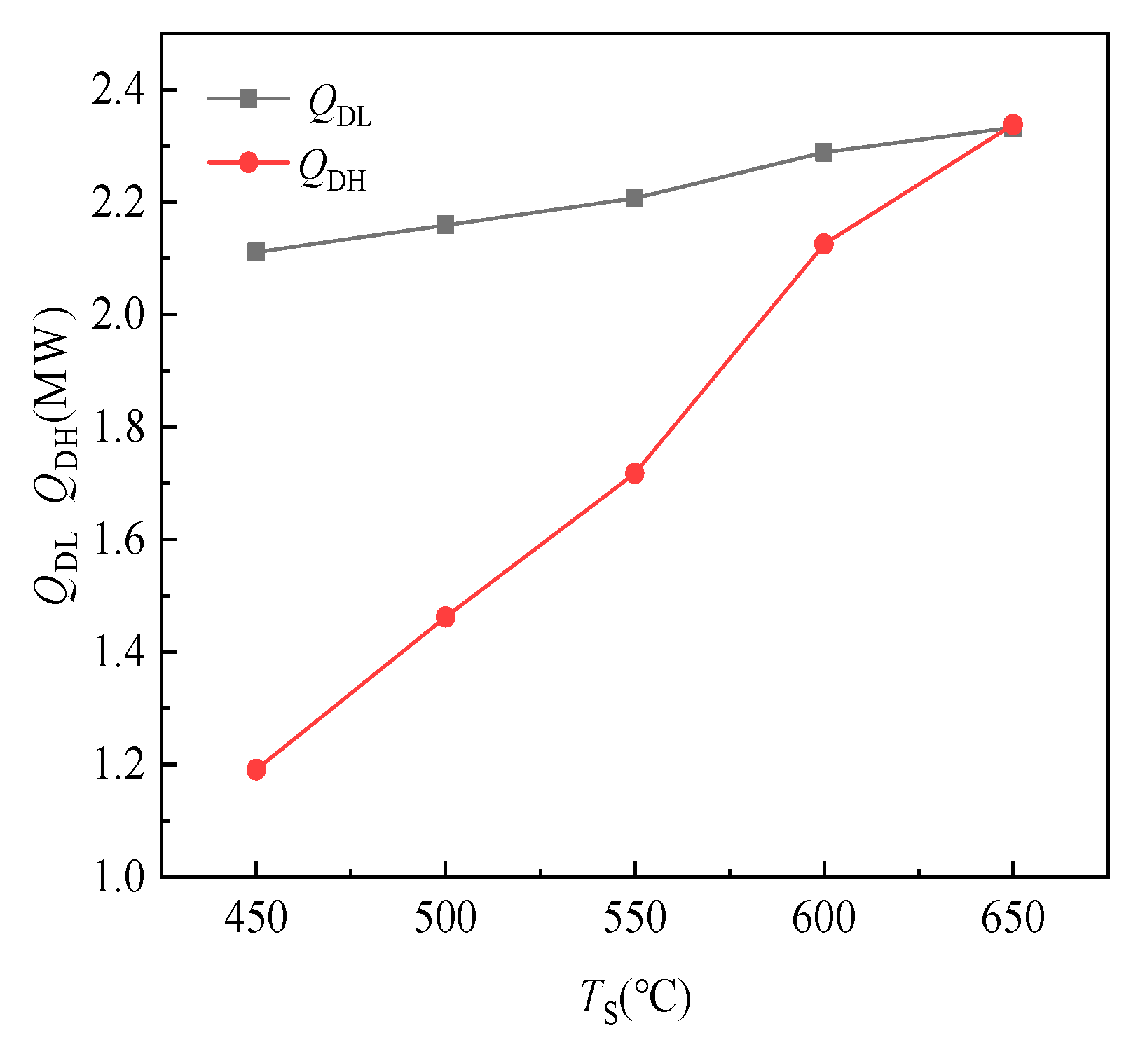
Figure 10 shows the variation pattern of the energy level of the high- and low-temperature heat exchangers with the TS during the heat release process. For the energy level heat QDL of the low-temperature heat exchanger, as the TS increases from 450 °C to 650 °C, QDL gently increases from 2.1 MW to 2.3 MW. Meanwhile, the high-temperature heat exchanger heat exchange QDH rapidly increased from 1.2 MW to 2.3 MW. From the above data, it can be seen that during the heat release process, the energy level heat of the high- and low-temperature heat exchangers gradually increases with increasing TS; the energy level heat and heat loss of the low-temperature heat exchanger increase slightly with increasing TS. The high-temperature heat exchanger’s energy level heat and heat loss increased significantly with increasing TS, and the change was dramatic. From the numerical analysis of the energy level heat, the energy level heat of the low-temperature heat exchanger always has a relatively large impact on the TES and release performance of the graded TES system, but the resulting system exergy loss does not significantly increase with the increase in the inlet superheated steam. On the other hand, as the temperature of the superheated steam at the inlet of the system increases, the energy level of the high-temperature heat exchanger increases significantly, and the corresponding exergy loss increases significantly. Therefore, for the exothermic process, the increase in the exergy loss caused by the increase in the TS is principal because of the change in the energy level of the high-temperature heat exchanger.
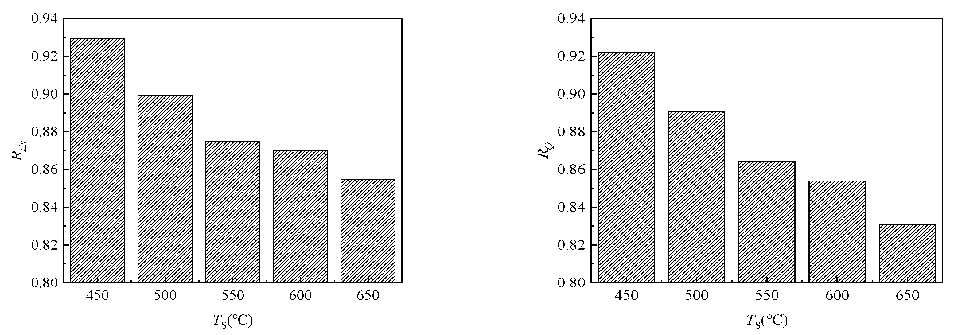
The variation pattern of the REx and RQ of the system with the TS is shown in Figure 11. As the inlet superheated steam increases, the REx and RQ of the system both decrease. As the TS increased from 450 °C to 650 °C, the REx of the system decreased from 92.9% to 85.5%. The RQ also showed a decreasing trend with the decrease in the superheated steam inlet temperature, and the RQ of the system decreased from 92.19% to 83.06%.

3.1.3. Effect of the TES Material Rm on the Graded TES System

When studying the effect of the TES material Rm, the fixed variable method was also used to study the TES system working conditions when the TES material Rm is 0.1, 0.3, 0.5, 0.7, and 0.9. Based on the temperature–enthalpy characteristic curve, the Rm’s effect on the graded TES’s energy level matching was analyzed.
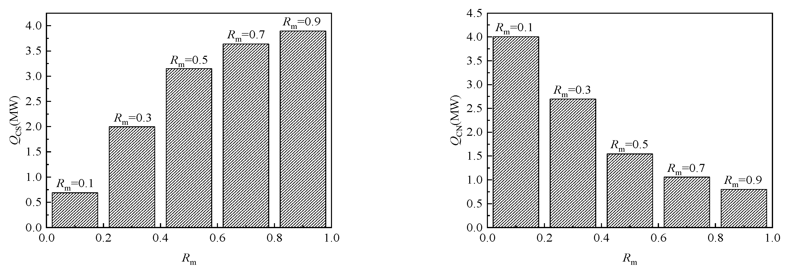
Figure 12 shows the variation in the sensible heat of the superheated steam absorbed by the sensible TES material with the Rm. It can be seen from the figure that as the Rm of the TES material increases, the QCS of the superheated steam section gradually increases, but the QCN gradually decreases. Due to the control of factors such as the TS, the outlet temperature of the TES material gradually decreases. Other factors need to be analyzed to obtain the change of the different Rm of the sensible TES material more clearly on the TES and release performance of the system.
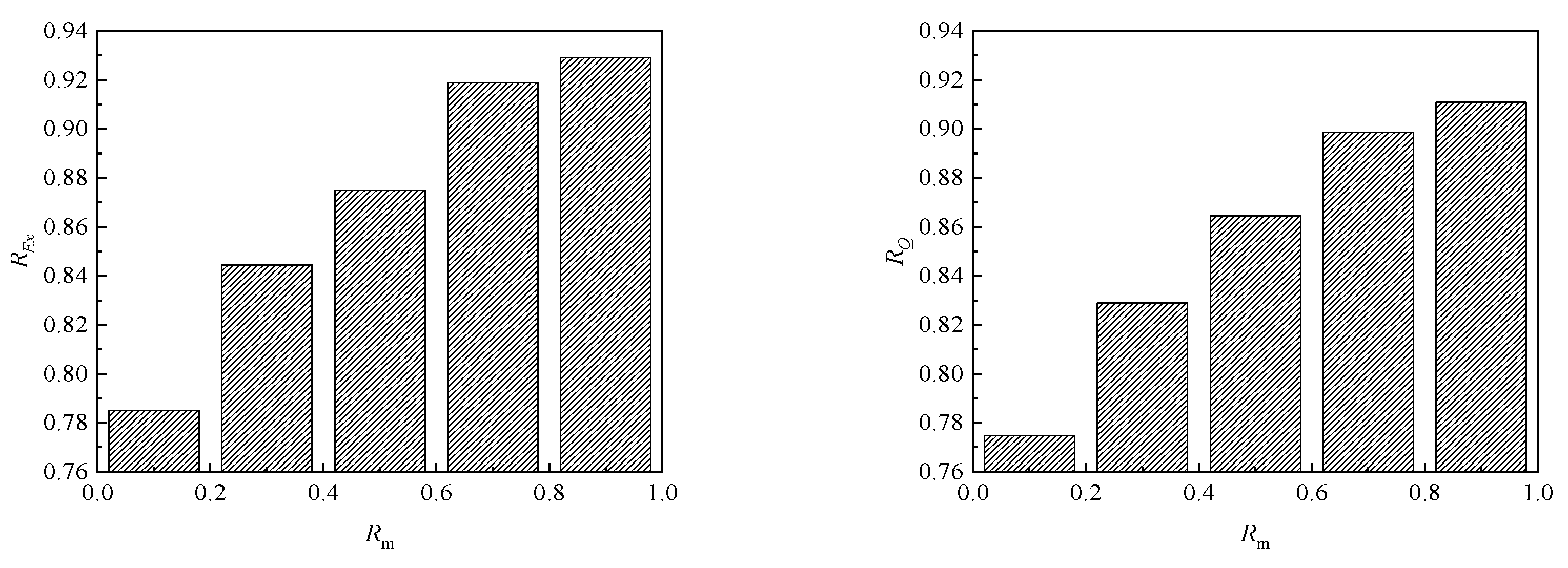
The variation pattern of the REx and RQ of the system with the Rm of the TES material is shown in Figure 13. As the Rm of the TES material increases, the REx and RQ of the system both increase. As the Rm of the TES material increases from 0.1 to 0.9, the REx and RQ of the system increase from 78.50% to 92.91%. Meanwhile, the RQ increased with the Rm of the TES material, from 77.47% to 91.08%.

3.2. Response Surface Method

Figure 14 shows the comparison between the actual calculated value and the predicted value using the graded TES system cost model as the optimization target. According to the distribution of the calculation results of different design combinations in the figure, the actual values are basically distributed near the prediction line of the regression model, indicating that the calculated results are basically consistent with the predicted values, and the prediction results of the regression model have high accuracy.
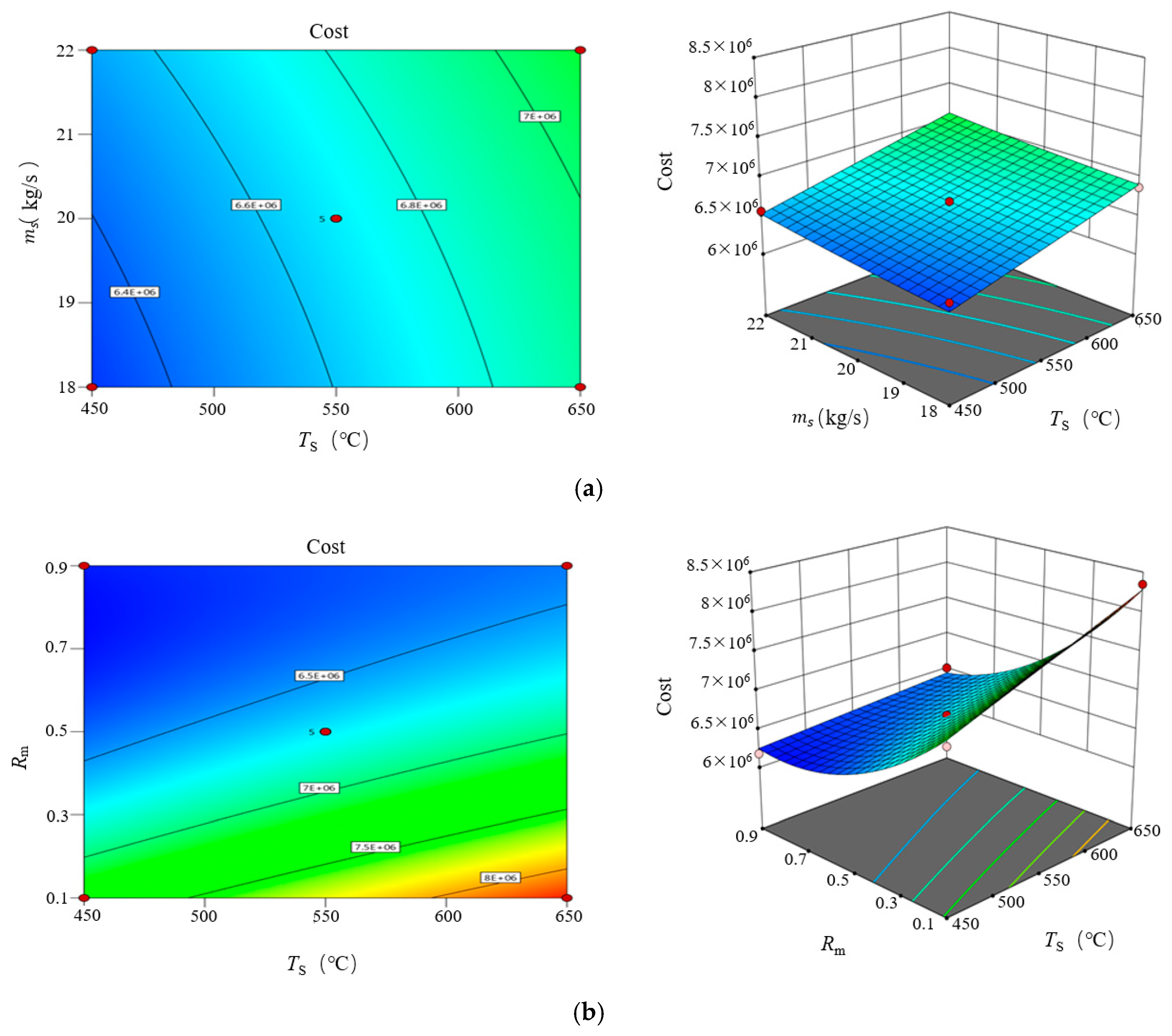
To further discuss the impact of each variable of the two-tank sensible-latent graded TES system on the system cost, Figure 15 shows the cost changes of the graded TES system under different system parameters. Figure 15a shows the interaction response surface diagram of the system cost between the superheated steam temperature and the sensible TES material mass flow at the inlet and outlet of the graded TES system when the Rm of the sensible TES material at the inlet and outlet of the graded TES system is 0.5. It can be seen from the figure that as the inlet steam temperature of the system increases, the system cost changes significantly. Taking the TES material ms of 18 kg/s as an example, when the system steam inlet temperature increases from 450 °C to 650 °C, the system cost increases from RMB 6.41 m to RMB 6.87 m. In comparison, when the steam inlet temperature of the system is 450 °C, the system cost only rises from RMB 6.41 m to RMB 6.56 m when the ms of the TES material changed.
Figure 15b shows the response surface diagram of the interaction between the superheated steam temperature at the inlet of the system and the Rm of sensible TES material on the system cost when the ms of the sensible TES material in the graded TES system is 20 kg/s. The figure shows that the Rm of the TES material and the temperature of the superheated steam at the inlet of the system have a large impact on the system cost, and the system cost changes significantly with the change in parameters. Taking the TES material Rm as an example, when the system steam inlet temperature increased from 450 °C to 650 °C, the system cost increased from RMB 7.21 m to RMB 8.35 m; when the system steam inlet temperature was 450 °C, the Rm of the TES material is changed, the system cost was only reduced from RMB 7.21 m to RMB 6.18 m.
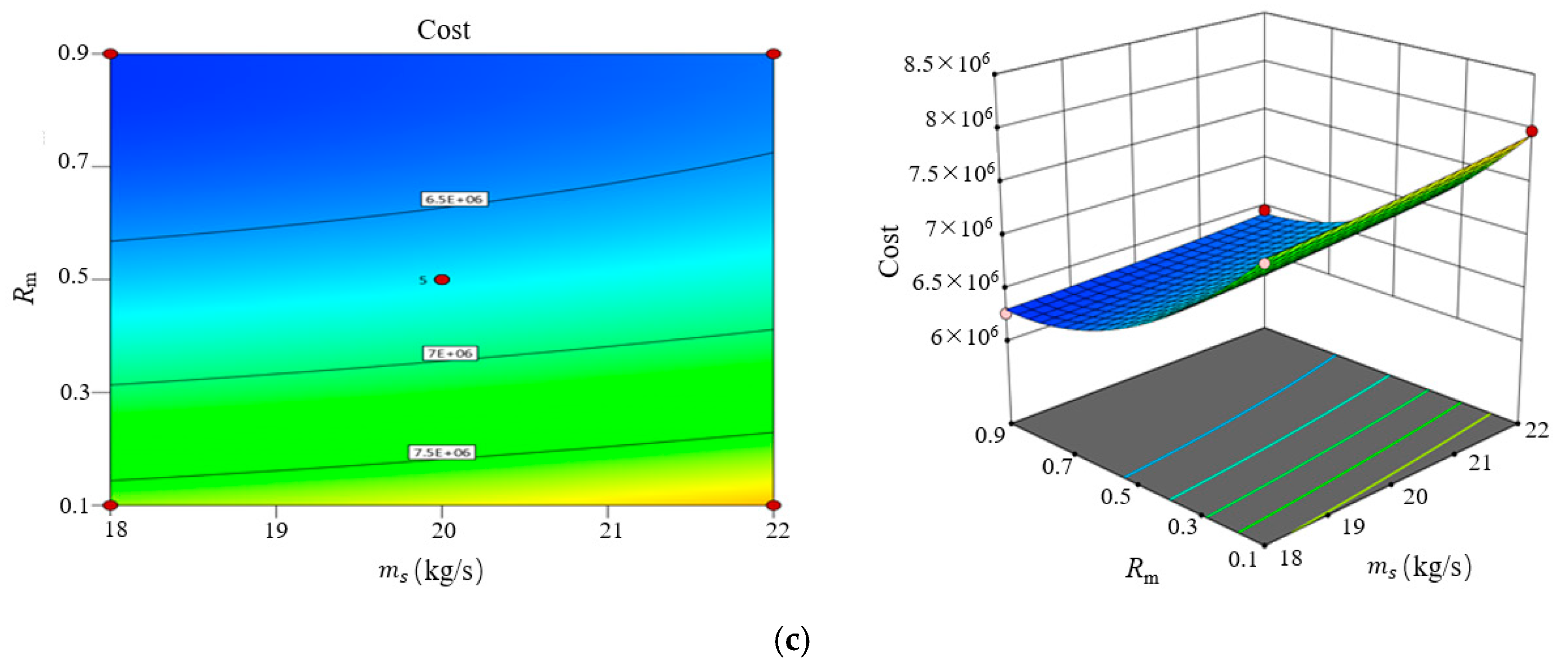
Figure 15c shows the interaction response surface of the sensible TES material Rm and the sensible TES material ms on the system cost when the inlet steam temperature of the graded TES system is 550 °C. It can be seen from the figure that as the Rm of the system sensible TES material increases, the system cost changes significantly. Taking the ms of the TES material as 18 kg/s as an example, when the ms of the sensible TES material in the system increases from 0.1 to 0.9, the system cost is reduced from RMB 7.62 m to RMB 6.26 m. In comparison, when the Rm of the TES material in the system is 0.1, the system cost only rises from RMB 7.62 m to RMB 7.99 m when the ms of the TES material is changed.

3.3. Rapid System Prediction Model Based on Support Vector Machine

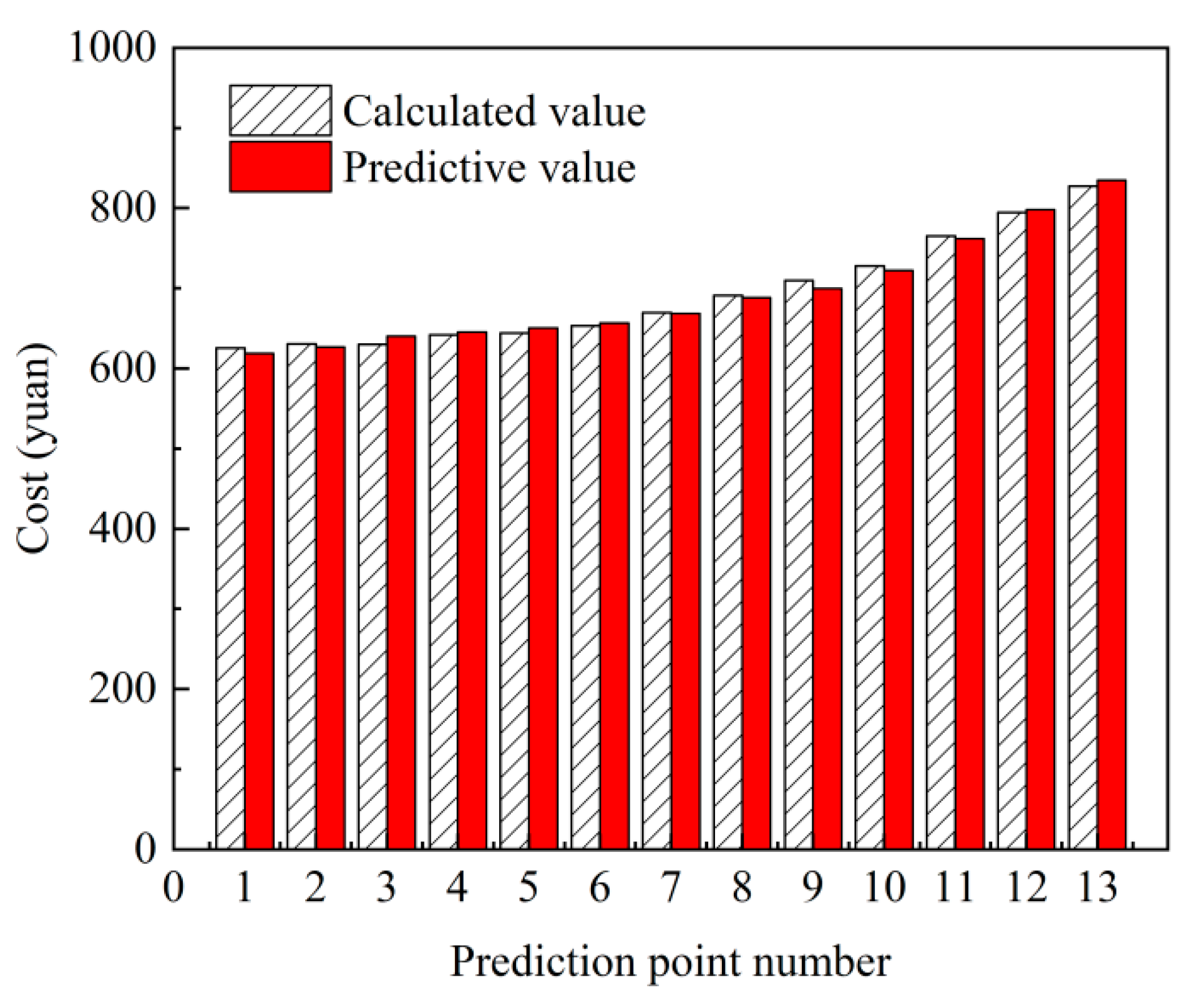
The thermodynamic calculation results of the above BBD design samples were used to establish a fast model of the graded TES, the REx and cost of the system were determined. The comparison results are shown in Figure 16. The results of the comparison between the predicted values and the calculated values of most of the design samples are good, which proves the reliability of the prediction model. Through the analysis, the prediction results of the SVM were compared with the thermodynamic calculation. The maximum errors were 4.39% and 3.26%, and mean deviation value was 0.86% and 0.82%. In summary, the SVM rapid prediction model obtained in this work has high accuracy and can accurately and rapidly predict the REx and cost of the graded TES.

3.4. Multi-Objective Optimization Based on the NSGA-II Algorithm

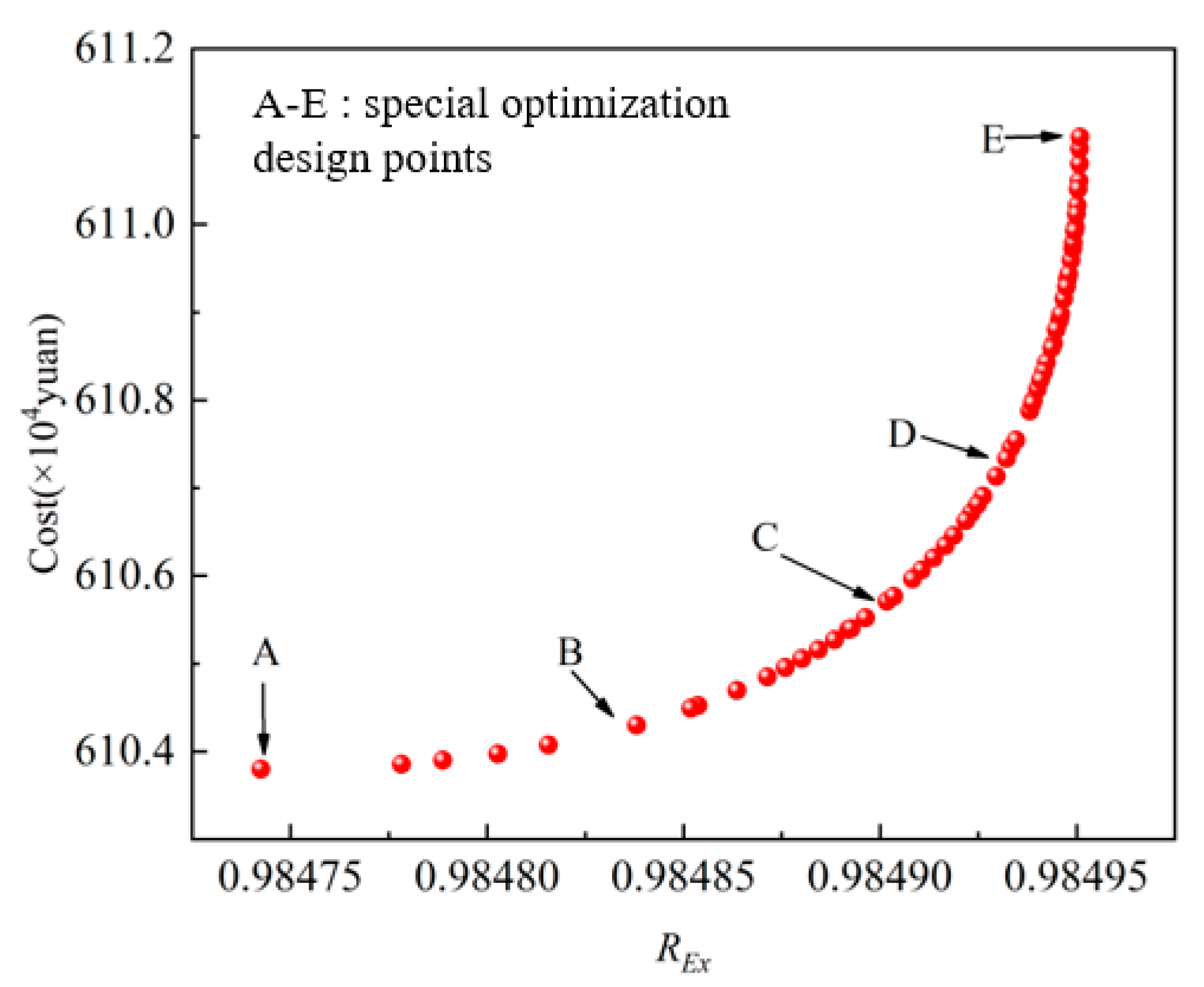
The multi-objective optimization of the graded TES system studied in this section uses the Rm of the TES material at the inlet and outlet of the system buffer tank, the TS, and the Rm of the TES material as the optimized fitness values. The overall cost is used as two functions of the optimization objective. Figure 17 shows the calculation results.
It can be analyzed from the optimization implementation results in the figure that a total of 60 nondominant Pareto optimal solution sets are obtained. The variance trend of the two targets in the figure is not obvious. The primary cause is that when the Rm of the system sensible TES material and the inlet super steamed steam temperature reaches the optimal value, the REx and cost of the system have been basically determined and will only fluctuate slightly with the variation of ms of TES materials. This also confirms that the factors in the response surface method affect the research results. There are five special optimization design points in the optimization solution set. The REx and cost at point A are at the lowest level, and the REx and cost at point E are at the highest level. In the process of moving from point A to point B, the REx increase is more significant than cost increases, and while moving from point D to point E, the significance of the increase in cost is much greater than the significance of the increase in REx. In the two-tank sensible-latent graded TES system studied in this paper, point C is an optimal design point for the REx and cost of the system. Table 5 shows the corresponding factor design.
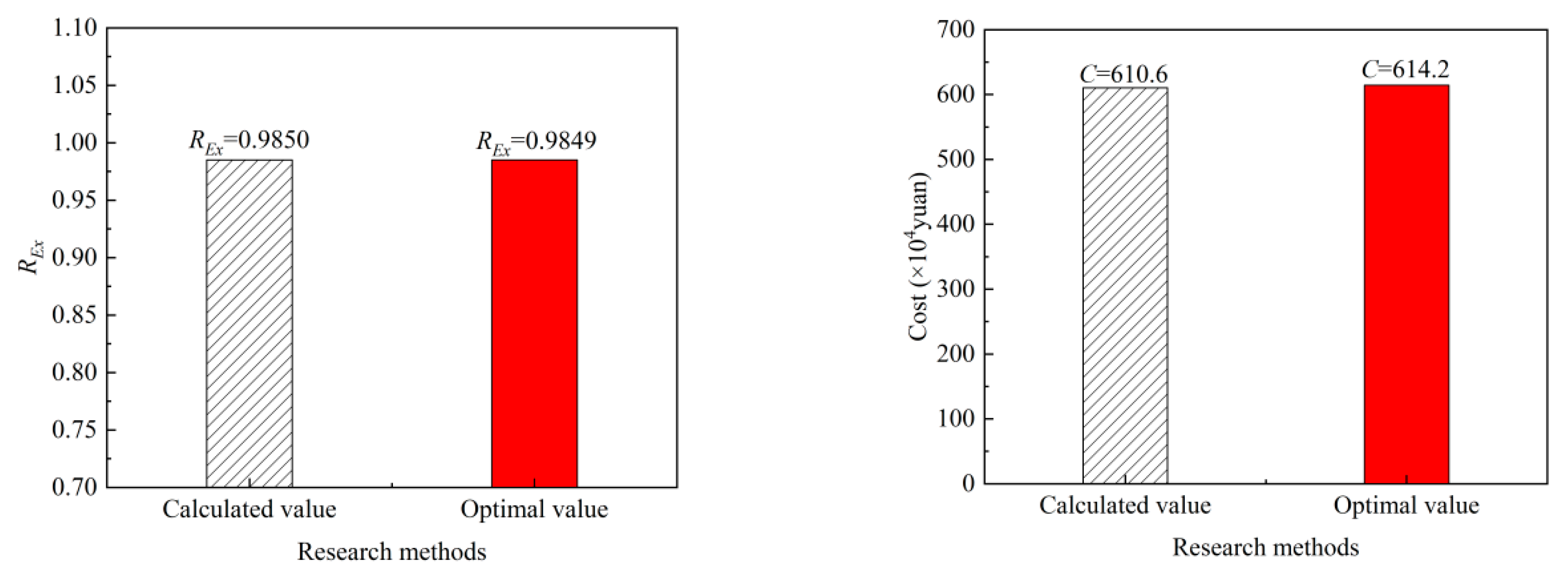
Figure 18 compares the calculation results of REx and cost at point C and the results of multi-objective optimization. As shown in the figure, according to the comparison, it was found that the difference between the calculation results of REx and cost and the multi-objective optimization result is 0.0001 and RMB 36,000, respectively, and the error is within the allowable range. In addition, the REx and cost of the graded TES can be accurately predicted by the prediction model.
Figure 19 compares the calculation results of the REx and cost of the samples before and after optimization. As shown in the figure, the results show that after optimization, the calculation result of REx is 11.01% higher than that before optimization, and the cost calculation result after optimization is reduced by RMB 585,000 compared with that before optimization. It proves that the optimization model has a significant optimization effect while ensuring high accuracy.

4. Conclusions

The present study established a data-driven surrogate model for a two-tank sensible-latent graded TES system by using the SVM. Then, the NSGA-II algorithm is used for multi-objective optimization of the graded TES system, in which the efficiency and cost of the graded TES are calculated using the surrogate model. The conclusions of the study are as follows:
  • Using the response surface method as the objective function, the significance of the impact of the three factors is studied. The results show that the system TS and the Rm of the sensible TES material have a significant impact on the system cost, and there is an optimal mass flow of sensible TES material, thereby maximizing the overall performance of the system.
  • The rapid cost prediction model of the graded TES based on SVM is trained. The results showed that the predicted cost was in good agreement with the thermodynamic calculation results. The maximum error is 3.26%, and the average error is 0.82%, which aligns with the demand for rapid performance prediction of the graded TES system.
  • By comparing the REx and cost corresponding to design point C obtained from the multi-objective optimization with the thermodynamic calculation results, the REx calculation result after optimization was 11.01% higher than that before optimization, and the cost calculation result after optimization was 585,000 yuan less than that before optimization. Its accuracy is at a high level, and the optimization effect is obvious.

Author Contributions

Conceptualization, B.Y.; Methodology, Z.Z. and R.B.; Investigation, Z.Z.; Writing—original draft, Z.Z.; Writing—review & editing, Y.D. and D.S.; Visualization, Z.Z.; Funding acquisition, Y.D. and B.Y. All authors have read and agreed to the published version of the manuscript.

Funding

This work is supported by the National Key R&D Program of China (No. 2021YFF0500401), the National Natural Science Foundation of China (Nos. 51961135102, 51906018), the fund of the Beijing Municipal Education Commission (No. 22019821001), and the Award Cultivation Foundation from Beijing Institute of Petrochemical Technology (No. BIPTACF-002).

Data Availability Statement

Not applicable.

Conflicts of Interest

The authors declare no conflict of interest.

Abbreviations

Qheat quantity (kJ)
pworking pressure (MPa)
ttime (h)
η efficiency (%)
Exexergy(W)
cpspecific heat (J/kg·K)
Ttemperature (℃)
Henthalpy (J)
Sentropy (J/K)
Vvolume (m3)
nratio of the tank’s inner diameter and height (-)
Ccost (RMB)
ρ density
Greek letters
εefficiency of heat exchanger[-]
Δdifference[-]
Subscripts
0turbo-generator
eenvironment
ccold
hhot
smThermal energy storage material
ststeel material
*unit price
TESThermal energy storage
STPsolar thermal power
ANNartificial neural network
SVMsupport vector machine
NSGAnondominated sorting genetic algorithm
CCDcentral composite design
BBDBox–Behnken design

References

  1. Al-Habaibeh, A.; Shakmak, B.; Fanshawe, S. Assessment of a novel technology for a stratified hot water energy storage—The water snake. Appl. Energy 2018, 222, 189–198. [Google Scholar] [CrossRef] [Green Version]
  2. Guo, S.; Liu, Q.; Sun, J.; Jin, H. A review on the utilization of hybrid renewable energy. Renew. Sustain. Energy Rev. 2018, 91, 1121–1147. [Google Scholar] [CrossRef]
  3. Liu, L.; Wang, R.; Wang, Y.; Li, W.; Sun, J.; Guo, Y.; Qu, W.; Li, W.; Zhao, C. Comprehensive analysis and optimization of combined cooling heating and power system integrated with solar thermal energy and thermal energy storage. Energy Convers. Manag. 2023, 275, 116464. [Google Scholar] [CrossRef]
  4. Ravi Kumar, K.; Krishna Chatanya, N.V.V.; Sendhil Kumar, N. Solar thermal energy technologies and its applications for process heating and power generation—A review. J. Clean. Prod. 2021, 282, 125296. [Google Scholar] [CrossRef]
  5. Zayed, M.E.; Zhao, J.; Li, W.; Sadek, S.; Elsheikh, A.H. Applications of Artificial Neural Networks in Concentrating Solar Power Systems. In Artificial Neural Networks for Renewable Energy Systems and Manufacturing Applications; Academic Press: Cambridge, MA, USA, 2021. [Google Scholar]
  6. Behar, O. Solar thermal power plants—A review of configurations and performance comparison. Renew. Sustain. Energy Rev. 2018, 92, 608–627. [Google Scholar] [CrossRef]
  7. Zayed, M.E.; Zhao, J.; Elsheikh, A.H.; Li, W.; Sadek, S.; Aboelmaaref, M.M. A comprehensive review on Dish/Stirling concentrated solar power systems: Design, optical and geometrical analyses, thermal performance assessment, and applications. J. Clean. Prod. 2021, 283, 124664. [Google Scholar] [CrossRef]
  8. Milian, Y.E.; Ushak, S.; Cabeza, L.F.; Grageda, M. Advances in the development of latent heat storage materials based on inorganic lithium salts. Sol. Energy Mater. Sol. Cells 2020, 208, 110344. [Google Scholar] [CrossRef]
  9. Suresh, C.; Saini, R.P. Thermal performance of sensible and latent heat thermal energy storage systems. Int. J. Energy Res. 2020, 44, 4743–4758. [Google Scholar] [CrossRef]
  10. Ben Khedher, N.; Bantan, R.A.; Kolsi, L.; Omri, M. Performance investigation of a vertically configured LHTES via the combination of nano-enhanced PCM and fins: Experimental and numerical approaches. Int. Commun. Heat Mass Transf. 2022, 137, 106246. [Google Scholar] [CrossRef]
  11. Ben Khedher, N.; Ben Nasrallah, S. Three-Dimensional Simulation of a porous thermal energy storage system using solid-liquid phase change material. J. Porous Media 2011, 14, 777–790. [Google Scholar]
  12. Wang, K.; Jia, P.-S.; Zhang, Y.; Zhang, Z.-D.; Wang, T.; Min, C.-H. Thermal-fluid-mechanical analysis of tubular solar receiver panels using supercritical CO2 as heat transfer fluid under non-uniform solar flux distribution. Sol. Energy 2021, 223, 72–86. [Google Scholar] [CrossRef]
  13. Malviya, R.; Agrawal, A.; Baredar, P.V. A comprehensive review of different heat transfer working fluids for solar thermal parabolic trough concentrator. Mater. Today Proc. 2021, 46, 5490–5500. [Google Scholar] [CrossRef]
  14. Yilmazoglu, M.Z. Effects of the selection of heat transfer fluid and condenser type on the performance of a solar thermal power plant with technoeconomic approach. Energy Convers. Manag. 2016, 111, 271–278. [Google Scholar] [CrossRef]
  15. Laing, D.; Bahl, C.; Bauer, T.; Lehmann, D.; Steinmann, W.-D. Thermal energy storage for direct steam generation. Sol. Energy 2011, 85, 627–633. [Google Scholar] [CrossRef]
  16. Eck, M.; Eickhoff, M.; Fontela, P.; Gathmann, N.; Meyer-Grünefeldt, M.; Hillebrand, S.J.; Schulte-Fischedick, J. Direct Steam Generation in parabolic troughs at 500 °C—First results of the REAL-DISS project. In Proceedings of the 17th Solar PACES Conference, Granada, Spain, 20–23 September 2011. [Google Scholar]
  17. Seitz, M.; Cetin, P.; Eck, M. Thermal storage concept for solar thermal power plants with direct steam generation. Energy Procedia 2014, 49, 993–1002. [Google Scholar] [CrossRef] [Green Version]
  18. Eck, M.; Eickhoff, M.; Fontela, P.; Laing, D.; Meyer-Grünefeldt, M.; Möllenhoff, M.; Nölke, M.; Vives, F.O.; Riffelmann, K.-J.; Sanchez-Biezma, A.; et al. Test and demonstration of the direct steam generation (DSG) at 500 °C. In Proceedings of the Solar PACES 2009—Electricity, Fuels and Clean Water Powered by the Sun, Berlin, Germany, 15–18 September 2009. [Google Scholar]
  19. Chen, Q.; Liang, X.-G.; Guo, Z.-Y. Entransy theory for the optimization of heat transfer—A review and update. Int. J. Heat Mass Transf. 2013, 63, 65–81. [Google Scholar] [CrossRef]
  20. Bian, R.; Deng, Y.; Feng, C. Performance and optimization study of graded thermal storage system for direct steam generation dish type solar thermal power. 2022; under review. [Google Scholar]
  21. Gumar, A.K.; Demir, F. Solar photovoltaic power estimation using meta-optimized neural networks. Energies 2022, 15, 8669. [Google Scholar] [CrossRef]
  22. Cortes, C.; Vapnik, V. Support-Vector Networks. Mach. Learn. 1995, 20, 273–297. [Google Scholar] [CrossRef]
  23. Zhang, J.; Zhu, H.; Yang, C.; Li, Y.; Wei, H. Multi-objective shape optimization of helico-axial multiphase pump impeller based on NSGA-II and ANN. Energy Convers. Manag. 2011, 52, 538–546. [Google Scholar] [CrossRef]
  24. Verma, S.; Pant, M.; Snasel, V. A Comprehensive Review on NSGA-II for Multi-Objective Combinatorial Optimization Problems. IEEE Access 2021, 9, 57757–57791. [Google Scholar] [CrossRef]
  25. Deb, K.; Pratap, A.; Agarwal, S.; Meyarivan, T.A.M.T. A fast and elitist multiobjective genetic algorithm: NSGA-II. IEEE Trans. Evol. Comput. 2002, 6, 182–197. [Google Scholar] [CrossRef] [Green Version]
  26. Hoseini Rahdar, M.; Heidari, M.; Ataei, A.; Choi, J.-K. Modeling and optimization of R-717 and R-134a ice thermal energy storage air conditioning systems using NSGA-II and MOPSO algorithms. Appl. Therm. Eng. 2016, 96, 217–227. [Google Scholar] [CrossRef]
  27. Yuan, X.; Cheng, W. Multi-objective optimization of household refrigerator with novel heat-storage condensers by Genetic algorithm. Energy Convers. Manag. 2014, 84, 550–561. [Google Scholar] [CrossRef]
  28. Li, Y.; Liu, G.; Liu, X.; Liao, S. Thermodynamic multi-objective optimization of a solar-dish Brayton system based on maximum power output, thermal efficiency and ecological performance. Renew. Energy 2016, 95, 465–473. [Google Scholar] [CrossRef]
  29. Gao, D.; Li, J.; Ren, X.; Hu, T.; Pei, G. A novel direct steam generation system based on the high-vacuum insulated flat plate solar collector. Renew. Energy 2022, 197, 966–977. [Google Scholar] [CrossRef]
  30. Hirsch, T.; Eck, M. Design of a phase separation system for a direct steam generation parabolic trough collector field. J. Sol. Energy Eng. -Trans. Asme 2008, 130, 011003. [Google Scholar] [CrossRef]
  31. Zarza, E.; Valenzuela, L.; León, J.; Hennecke, K.; Eck, M.; Weyers, H.-D.; Eickhoff, M. Direct steam generation in parabolic troughs: Final results and conclusions of the DISS project. Energy 2004, 29, 635–644. [Google Scholar] [CrossRef]
  32. Li, X.; Xu, E.; Song, S.; Wang, X.; Yuan, G. Dynamic simulation of two-tank indirect thermal energy storage system with molten salt. Renew. Energy 2017, 113, 1311–1319. [Google Scholar] [CrossRef]
  33. Peiró, G.; Prieto, C.; Gasia, J.; Jové, A.; Miró, L.; Cabeza, L.F. Two-tank molten salts thermal energy storage system for solar power plants at pilot plant scale: Lessons learnt and recommendations for its design, start-up and operation. Renew. Energy 2018, 121, 236–248. [Google Scholar] [CrossRef]
  34. Wan, Z.; Wei, J.; Qaisrani, M.A.; Fang, J.; Tu, N. Evaluation on thermal and mechanical performance of the hot tank in the two-tank molten salt heat storage system. Appl. Therm. Eng. 2020, 167, 114775. [Google Scholar] [CrossRef]
  35. Bejan, A. Entropy Generation Minimization. In Advanced Engineering Thermodynamics; John Wiley & Sons: New York, NY, USA, 1995. [Google Scholar]
  36. Guo, J.; Huai, X.; Cheng, K. The comparative analysis on thermal storage systems for solar power with direct steam generation. Renew. Energy 2018, 115, 217–225. [Google Scholar] [CrossRef]
  37. Guo, J.; Huai, X. Optimization design of heat exchanger in an irreversible regenerative Brayton cycle system. Appl. Therm. Eng. 2013, 58, 77–84. [Google Scholar] [CrossRef]
  38. Shah, R.K.; Sekulic, D.P. Fundamentals of heat exchanger design. In Fundamentals of Heat Exchanger Design; John Wiley & Sons: New York, NY, USA, 2002. [Google Scholar]
  39. Yusri, I.M.; Abdul Majeed, A.P.P.; Mamat, R.; Ghazali, M.F.; Awad, O.I.; Azmi, W.H. A review on the application of response surface method and artificial neural network in engine performance and exhaust emissions characteristics in alternative fuel. Renew. Sustain. Energy Rev. 2018, 90, 665–686. [Google Scholar] [CrossRef]
  40. Mohammadi, M.M.; Vossoughi, M.; Feilizadeh, M.; Rashtchian, D.; Moradi, S.; Alemzadeh, I. Effects of electrophoretic deposition parameters on the photocatalytic activity of TiO2 films: Optimization by response surface methodology. Colloids Surf. A Physicochem. Eng. Asp. 2014, 452, 1–8. [Google Scholar] [CrossRef]
  41. Shan, Z.; Luo, H.; Qin, S.H. Polymer ratio optimization based on support vector machine and genetic algorithm. Appl. Mech. Mater. 2013, 444–445, 1026–1032. [Google Scholar] [CrossRef]
Figure 1. Workflow of the dish-type direct steam thermal power generation system.
Energies 16 02404 g001
Figure 2. Sensible-latent graded TES with an intermediate tank.
Energies 16 02404 g002
Figure 3. The structure of support vector machine for regression.
Energies 16 02404 g003
Figure 4. Illustrative representation of the NSGA-II algorithm.
Energies 16 02404 g004
Figure 5. Optimization flow chart of the NSGA-II algorithm.
Energies 16 02404 g005
Figure 6. The law of sensible heat absorbed by superheated steam of sensible-latent storage materials increasing with the ms of TES materials.
Energies 16 02404 g006
Figure 7. The law of the heat exchange capacity of high and low-temperature heat exchangers increasing with the ms of TES materials during the heat release process.
Energies 16 02404 g007
Figure 8. The law of the heat exchange capacity of high- and low-temperature heat exchangers increases with the ms of TES materials during the process of heat release.
Energies 16 02404 g008
Figure 9. The law of sensible heat absorbed by sensible-latent storage materials increasing with the inlet steam temperature of the system.
Energies 16 02404 g009
Figure 10. The law of the heat exchange rate of high and low-temperature heat exchangers rising with the inlet steam temperature of the system during heat release.
Energies 16 02404 g010
Figure 11. The law of REx and t RQ increasing with TS.
Energies 16 02404 g011
Figure 12. The law of sensible heat absorbed by superheated steam of sensible-latent storage materials increases with the Rm of TES materials.
Energies 16 02404 g012
Figure 13. The law of system REx and RQ increasing with the Rm of TES materials in the heat release process.
Energies 16 02404 g013
Figure 14. Analysis chart of the calculated cost value and test predicted value.
Energies 16 02404 g014
Figure 15. Interaction of different design variables on the cost of graded multistage TES system. (a) Response surface diagram of the interaction between superheated steam temperature and ms of TES material on system cost. (b) Response surface diagram of the interaction between superheated steam temperature and Rm of TES materials for system cost. (c) Response surface diagram of the interaction between ms of TES material and Rm of TES material to system cost.
Energies 16 02404 g015aEnergies 16 02404 g015b
Figure 16. Comparison between the support vector machine’s predicted value and calculated value.
Energies 16 02404 g016aEnergies 16 02404 g016b
Figure 17. Pareto optimal solutions for the graded multistage TES system.
Energies 16 02404 g017
Figure 18. Multi-objective optimization simulation verification diagram of the graded TES system.
Energies 16 02404 g018
Figure 19. Comparison of the graded TES system before and after optimization.
Energies 16 02404 g019
Table 1. Unit price of different materials in thermal energy storage systems.
ParameterNumeric (RMB/t)
NaNO32548
Solar Salt3388
Steel tanks19,403
Table 2. Parameter design scheme of Box–Behnken Design.
NumberRmTs (℃)ms (kg/s)
10.565018
20.955022
30.545022
40.145020
50.955018
60.555020
70.965020
80.545018
90.555020
100.565022
110.155018
120.555020
130.165020
140.945020
150.155022
160.555020
170.555020
Table 3. Genetic algorithm parameter settings.
ParameterValues
Population200
Probability of crossing: Pc0.85
Probability of variation: Pm0.1
Number of iterations500
Table 4. Design table of calculation case.
Numberms (kg/s)Ts (℃)Rm
Benchmark205500.5
1185500.1
2195500.3
3205500.5
4215500.7
5225500.9
6204500.5
7205000.5
8205500.5
9206000.5
10206500.5
11205500.5
12205500.5
13205500.5
14205500.5
15205500.5
Table 5. Optimal design results of multi-objective optimization on point C for the graded TES system.
Design VariablesOptimization Results
Rm0.9
TS450 °C
ms19.1 kg/s
Disclaimer/Publisher’s Note: The statements, opinions and data contained in all publications are solely those of the individual author(s) and contributor(s) and not of MDPI and/or the editor(s). MDPI and/or the editor(s) disclaim responsibility for any injury to people or property resulting from any ideas, methods, instructions or products referred to in the content.