1. Introduction
In recent years, to alleviate the pressure of energy shortage and environmental pollution, new-energy vehicles have been widely used [
1,
2,
3]. New-energy vehicles could be mainly arranged in three classes as follows: pure electric vehicles, hybrid electric vehicles and extended-range electric vehicles (EREVs). Pure electric vehicles can achieve zero emissions, but the disadvantages such as long charging time, high battery capacity and poor endurance are still the bottlenecks preventing the widespread applications of pure electric vehicles [
4]. Hybrid electric vehicles have the advantages of high endurance ability and low battery capacity, but the powertrain system structure of hybrid electric vehicles is complex and costly. Moreover, since the main power of hybrid electric vehicles is provided by an internal combustion engine (ICE), the effects of energy conservation and emission reduction are limited [
5]. EREVs with high endurance ability, middle battery capacity and lower emissions have the advantages of pure electric vehicles and hybrid electric vehicles and avoid the disadvantages of them. Therefore, EREVs have attracted extensive attention [
6,
7].
As shown in
Figure 1, the powertrain system of EREVs includes battery packs, traction motor and a range extender composed of an ICE and a generator [
8]. The range extender and the traction motor in conventional EREVs are independent mechanically. When the battery is sufficient, the vehicle operates in pure electric state; when the battery is low, the range extender supplies power to the battery and traction motor, thus increasing the range of the vehicle [
9].
However, the existence of a range extender will reduce the interior space and increase the complexity and the cost of the powertrain system [
10,
11,
12,
13]. In addition, the output power of the ICE needs to be converted from mechanical power to electrical power and then from electrical power to mechanical power to drive the vehicle, which will reduce the efficiency of the system [
14,
15].
Dual-mechanical port machines (DPMs) can be employed to make the powertrain system more compact, which integrates the generator and the traction motor together. Nevertheless, the DPMs usually need brushes and slip rings to feed current, which causes the inevitable problems of frequent maintenance and friction loss [
16]. Brushless doubly fed machines (BDFMs) have obvious advantages of flexible power flow, improved efficiency and extended torque-speed characteristics, which make them a potentially promising candidate for new-energy vehicle applications [
17].
By incorporating the concept of the DPMs into the BDFMs, a cup-rotor permanent-magnet doubly fed machine (CRPM-DFM) was proposed in [
18]. The CRPM-DFM integrates the generator and the traction motor together, which saves interior space, reduces vehicle weight, and improves the powertrain system’s compactness. Moreover, the CRPM-DFM has no brush and slip ring, which improves the reliability and cost-effectiveness of the powertrain system. In addition, the CRPM-DFM transmits most of the output power of the ICE directly to the drive shaft in the form of electromagnetic power, which improves the efficiency of the powertrain system.
At present, there is little performance analysis of CRPM-DFM. The heat dispersion of the CRPM-DFM is studied, and a liquid cooling strategy of the CRPM-DFM is proposed in [
18]. The equivalent circuit of the CRPM-DFM is given in [
19]. The mathematical model of the CRPM-DFM under a two-phase rotor coordinate system has been established, and the open-loop working performance is analyzed [
20]. However, different from the above studies, based on the previous work of the first author of this paper on modeling and control methods of a brushless doubly fed machine, the state space model of the CRPM-DFM in a synchronous coordinate system has been established. Then the static load capacity of the CRPM-DFM is analyzed, and the vector control strategy is proposed in [
21].
To maximize the performance of CRPM-DFM, the appropriate machine control method should be designed. CRPM-DFM evolved from BDFM. The control method design of CRPM-DFM can refer to the existing research results of BDFM. The control methods of BDFM include scalar control, direct torque control and vector control [
22,
23,
24]. The scalar control method has poor disturbance-rejection ability and is hardly used at present. A direct torque control method is simple, but it has the disadvantages of large computation and large torque ripple. Vector control is widely used and can be realized based on a double synchronous coordinate system and unified synchronous coordinate system, respectively. The speed adjustment range of vector control based on the double synchronous coordinate system is narrow, which is not suitable for the electric-vehicle driving field. The vector control based on the unified synchronous coordinate system is first oriented according to the magnetic field of the control machine or the power machine. Then, the variables of each machine are placed in a unified coordinate system by using the slip frequency relation between the windings of the two machines under the steady-state condition, and the BDFM is controlled by power machine stator field orientation, but there is coupling between flux and torque. To solve this problem, feedback linearization control of a brushless doubly fed motor is proposed in the literature [
25]. In addition to the machine torque, the vector sum of the rotor flux of the power machine and the control machine is also selected as the control object, which realizes the decoupling control of the rotor flux and the torque. Besides, the literature [
26] proposes the maximum torque per ampere (MTPA) control of BDFM, which minimizes the stator current amplitude when the output torque is the same, thus improving machine efficiency.
The motivation of this paper is to analysis the performance of the CRPM-DFM, which includes the operating principle, torque characteristics, and efficiency of the CRPM-DFM under different operating modes. In addition, to improve the driving performance and fuel economy of the powertrain system, the control strategy of CRPM-DFM and speed optimization strategy of ICE are proposed.
This paper is organized as follows:
Section 2 introduces the structure, operating principle and operating modes of the powertrain system based on CRPM-DFM.
Section 3 establishes the mathematical model and derives the feedback-linearization control method of CRPM-DFM.
Section 4 analyzes the torque characteristic and derives the load torque boundaries with the sinusoidal steady-state solution of CRPM-DFM.
Section 5 proposes the MTPA control method and analyzes the efficiency of CRPM-DFM in different operating modes.
Section 6 proposes a speed optimization strategy of ICE.
Section 7 built a simulation platform of the EREVs’ powertrain system based on CRPM-DFM and verifies the driving performance and fuel economy of the powertrain system.
Section 8 is the summary of the whole paper.
2. The Powertrain System Based on CRPM-DFM
2.1. Structure and Operating Principle of the Powertrain System Based on CRPM-DFM
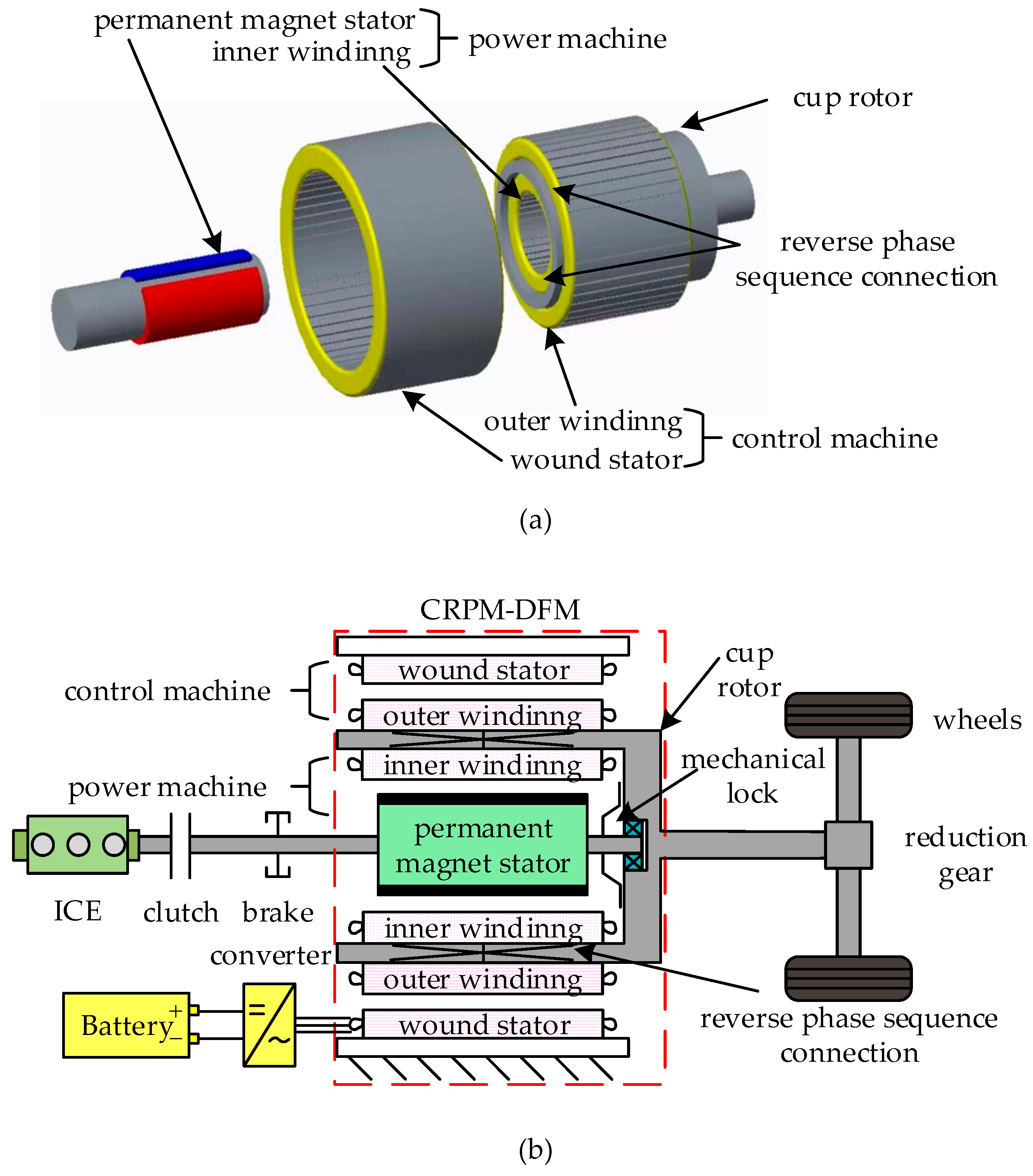
The construction of CRPM-DFM and the structure diagram of the powertrain system based on the CRPM-DFM are shown in
Figure 2. It can be seen that the powertrain system based on the CRPM-DFM is constructed by an ICE, a CRPM-DFM, a bidirectional converter module, and a battery pack, where the CRPM-DFM consists of a wound stator, a rotating permanent-magnet stator and a cup rotor. The connection between the cup-rotor windings is a reverse phase sequence. The ICE is connected to the rotating permanent-magnet stator through a clutch. The reduction gear is connected to the cup rotor for driving the vehicle. The bidirectional converter is connected to the wound stator through which electrical energy is absorbed from or charged to the battery. The mechanical lock can be controlled independently, either to lock the permanent-magnet stator and cup rotor into one, or to allow them to rotate independently, in conjunction with the engagement or disengagement of the clutch, to achieve different operating modes.
The power machine is a permanent-magnet synchronous motor whose stator can be rotated, including the cup-rotor inner winding and the permanent-magnet stator and the pole number of ; the control machine is an asynchronous machine, including the wound stator and the outer winding of cup rotor and the pole number of . Among them, there is only an electrical connection between the inner and outer windings of the cup rotor and no magnetic coupling.
When the cup rotor and permanent-magnet stator can rotate independently, the CRPM-DFM is operating in doubly fed mode. Since the rotor windings are connected in reverse phase sequence, the air-gap magnetic fields on both sides of the cup rotor rotate in reverse at the same angular velocity relative to the rotor when the CRPM-DFM is running. Therefore, the cup-rotor speed can be obtained as:
From Equation (1), the cup rotor speed can be obtained according to the power supply frequency of the wound stator and the permanent-magnet stator speed. When , it is said that the CRPM-DFM runs in super-synchronous mode; when , it runs in sub-synchronous mode, and when , in synchronous mode.
The sum of the torque acting on the cup rotor by the power machine and the control machine is the output torque of the cup rotor, that is:
Ignoring the machine losses, the input and output power of the CRPM-DFM meet the following relation.
Combining Equations (1)–(3), the relationship can be obtained that the electromagnetic torques of the power machine and control machine are proportional to their pole pairs.
It can be seen from Equations (1)–(4) that the CRPM-DFM is a speed coupler similar to a planetary gear, in that the ratio of the pole number between the power machine and control machine is equal to the ratio of the tooth number between the ring gear and sun gear, and the electromagnetic torques of the wound stator and permanent magnet stator applied to the cup rotor corresponds to the torques of the ring gear and sun gear applied to the planet carrier, respectively. When the CRPM-DFM works in super-synchronous mode (the magnetic fields of both the power machine and control machine rotate in the positive direction), the power required by the vehicle is equal to the sum of the power output of the battery and the power output of the ICE; when the CRPM-DFM works in synchronous mode (the power machine magnetic field rotates in the positive direction, and the control machine magnetic field is stationary), the power required by the vehicle is provided by the ICE and the battery is not working; when the CRPM-DFM works in sub-synchronous mode (the power machine magnetic field rotates in the positive direction, and the control machine magnetic field rotates in the reverse direction), the power output of the ICE is equal to the sum of the power required by the vehicle and the power absorbed by the battery.
For the powertrain system based on CRPM-DFM, in doubly fed mode, the torque of the ICE is equal to the torque of the power machine. Hence, according to Equations (2) and (4), the relationship of the torques of cup rotor and ICE can be obtained.
In the configuration of the powertrain system based on CRPM-DFM, Equation (5) has certain practical significance on how to choose the size of CRPM-DFM and ICE. In the application of EREVs, the power of ICE is relatively small. In this design, the rated power of ICE is slightly larger than the average power of the driving vehicle, and the shortage of peak power and peak torque is made up by the control machine. In addition, the control machine also needs to meet the power and torque requirements under pure electric driving mode, so .
2.2. Basic Operating Modes of the Powertrain System Based on CRPM-DFM
When the locking device locks the rotor and the permanent magnet into one, or enables them to rotate independently, the CRPM-DFM has two working modes: asynchronous mode and doubly fed mode.
In asynchronous mode, the rotor and the permanent magnet are locked together. At this time, there is no electromagnetic induction between the rotor winding and the magnetic field generated by the permanent magnet, and the power machine does not output power. The CRPM-DFM is equivalent to an asynchronous machine with rotor series resistance and inductance. Since the permeability of the permanent magnet stator and the air is approximately equal, the air gap of the control machine is much smaller than that of the power machine. In this case, the inductance of the power machine rotor is very small, the armature reaction is weak and the magnetic circuit of power machine will not saturate because of a large current.
In doubly fed mode, the rotor and the permanent magnet rotate independently, and the torque direction of the two machines is the same, but when the power supply frequency of control machine is greater than zero or less than zero, the power flow of the control machine is reversed, corresponding to the discharging or charging of the battery. The vehicle-requested torque is proportionally distributed to the power machine and control machine. By controlling , the ICE speed optimization can be realized to reduce fuel consumption and restrict the fluctuation of battery SOC simultaneously.
As shown in
Figure 2, the CRPM-DFM is used for a vehicle’s hybrid power plant. The asynchronous mode is only used for pure electric mode to drive vehicles or brake vehicles, and to start the ICE. The doubly fed mode is only used for driving vehicles and stopping to charge batteries. Taking forward driving as an example, the conversion sequence from doubly fed mode to asynchronous mode is as follows: release the throttle → drive torque returns to zero → press the brake pedal → release the clutch → the brake makes the permanent magnet stator speed slow down to the same speed as the cup rotor → the lock device locks the permanent magnet stator and the cup rotor → the motor operates in asynchronous mode; on the contrary, the conversion sequence from asynchronous mode to doubly fed mode is as follows: release the brake pedal → brake torque returns to zero → press down the accelerator pedal → release the locking device → clutch closes → the CRPM-DFM works in doubly fed mode.
Because the control method of the asynchronous mode is the same as that of a general asynchronous motor, we will not repeat it here. The control method and characteristics of CRPM-DFM in doubly fed mode are discussed in the following part. As for the content of parking charging, only an efficiency map is provided in this paper.
4. Torque Characteristic Analysis of CRPM-DFM
For the given values of speed difference between a permanent-magnet stator and cup rotor, rotor flux and load torque, feedback linearization control can give two solutions: a sinusoidal steady-state solution and non-sinusoidal steady-state solution. Taking the machine parameters in
Table A1 as an example, the typical response waveforms of a sinusoidal steady-state solution and non-sinusoidal steady-state solution of the CRPM-DFM under feedback linearization control are shown in
Figure 4.
Under a different permanent-magnet flux, rotor flux and speed difference, the range of torque with the sinusoidal steady-state solution is different. When the output torque exceeds the load torque boundaries, the non-sinusoidal steady-state solution exists, although the machine can still output a stable speed and torque, but the voltage and current change rate increases, and the amplitude will oscillate periodically, which requires the converter to improve the voltage and current tolerance level and provide a higher DC voltage; otherwise, the CRPM-DFM will go out of control. However, the IGBT with higher voltage and current tolerance level will increase the cost of the system. Therefore, for the powertrain system based on CRPM-DFM, the use of a non-sinusoidal steady-state solution will be avoided unless it is absolutely necessary.
The sinusoidal steady-state solution corresponds to the constant solution of Equation (20) and the constant slip frequency. For a certain permanent magnet stator speed, slip frequency and rotor flux, a set of algebraic equations can be obtained by making
,
and
in Equation (20). Then, the torque range obtained when the equations have a constant solution is the torque range with the sinusoidal steady-state solution of CRPM-DFM. Therefore, by substituting the first two lines of Equation (20) into the third line of Equation (20), the load torque can be expressed as:
According to Equation (27), because the amplitude of the m-axis component of the permanent-magnet flux cannot exceed the amplitude of the permanent-magnet flux, when
or
, the upper and lower load torque boundaries can be obtained. Taking
as an example, the values and width of load torque boundaries are:
From Equation (28), the upper, lower and width of load torque boundaries are proportional to the speed difference and inversely proportional to the rotor resistance. Because the numbers in the two square brackets in the expressions of lower and upper torque boundaries are not equal, the slopes of the lower and upper torque boundaries are different as the speed difference changes. Besides, the change of the lower and upper torque boundaries with the rotor flux amplitude of the control machine is a quadratic curve, the lower and upper torque boundaries are asymmetric, especially when , the upper boundary is and the lower boundary is 0; changing the sign of speed difference, the lower and upper torque boundaries will switch but the width remains the same.
Taking the machine parameters in
Table A1 as an example, and the per-unit value of torque is applied, which is
,
, the load torque boundaries of CRPM-DFM are obtained, as shown in
Figure 5.
To further illustrate, let
in
Figure 5 to get the curve of
Figure 6. When
, the lower and upper torque boundaries of the CRPM-DFM will decrease with the increase in the amplitude of rotor flux, and even
. When
, the lower and upper torque boundaries of the CRPM-DFM will increase with the increase in the amplitude of rotor flux, and even
, as shown in
Figure 6a,b. When the amplitude of rotor flux is constant, the upper, lower and width of load torque boundaries will linearly increase with the increase of
; when the sign of
changes, the lower and upper torque boundaries will switch, as shown in
Figure 6c.
According to Equation (28) and
Figure 6, only when the speed difference is slight will the output torque of CRPM-DFM with sinusoidal steady-state solution be limited. In most cases, the rotor flux amplitude and the speed difference can be appropriately adjusted to make the maximum output torque of CRPM-DFM with sinusoidal steady-state solution to meet the driving requirements of several times the rated torque. Only in some special cases can the CRPM-DFM be driven under a non-sinusoidal steady-state solution, such as starting the ICE when the vehicle is parked; at this time, the ICE speed and vehicle speed are both zero:
. In addition, as described in the next section, the maximum torque per ampere (MTPA) control can effectively reduce the stator current of CRPM-DFM.
6. ICE Speed Optimization Strategy
In hybrid driving mode, the CRPM-DFM works in doubly fed mode, and the vehicle-requested torque is distributed to the ICE and control machine in proportion to the pole pairs. In this case, the CRPM-DFM is equivalent to a speed coupler and the ICE speed should be optimized to adjust the power distribution of the ICE and battery. Then, the fuel consumption and battery SOC fluctuation can be reduced.
A 12 kW petrol ICE is used in this paper, and the fuel consumption map of ICE is shown in
Figure 12. The optimal operating curve is a curve formed by connecting the speed and torque points corresponding to the minimum fuel consumption rate of each output power, and ICE speed
in the optimal operating curve can be roughly expressed as a quadratic function of ICE torque
[
27], as shown in the red line in
Figure 12.
Furthermore, a 30 AH nickel metal hydride (NiMH) battery with a large discharge rate is selected; to improve the performance of the battery pack and prolong its service life, battery SOC should be kept in the efficient working zone as far as possible. In this paper, the SOC maximum value is 0.7 and the SOC minimum value is 0.6.
When the vehicle is running, the pedal-torque reference value will be given; if the battery SOC is within the efficient working zone, the ICE speed can be optimized according to Equation (35) by adjusting the power supply frequency of the converter to reduce fuel consumption, unless the speed difference is too small to obtain the desired torque within the sinusoidal steady-state solution range. Therefore, the speed difference
should be maintained above
, as according to
Figure 5.
In addition, a PI controller is used to restrain battery SOC fluctuation. PI controller input is the difference between the reference SOC value and actual SOC value; output is the ICE speed adjustment nice-soc. When the actual SOC value is higher than the reference SOC value, the ICE speed adjustment is reduced to increase the battery output power and, thus, reduce the SOC. When the actual SOC value is lower than the reference SOC value, the ICE speed adjustment is increased to reduce the battery output and, thus, increase the SOC.
Therefore, with the goal of reducing fuel consumption and SOC fluctuation, an ICE speed optimization strategy that can be applied online is proposed, and the flowchart is shown in
Figure 13.
8. Conclusions
For the coupling devices of new-energy vehicles, there are three kinds: torque coupling, speed coupling and power coupling. The complexity is increased in turn, and the fuel saving rate is also better in turn. The most prominent is the power coupling device of the two motors and mechanical planetary gear of the Prius, which can realize power coupling. The dynamic coupling device of CRPM-DFM discussed in this paper is similar to the planetary gear mechanism, which can realize the speed coupling, but there is no mechanical mechanism, and the generator and motor are integrated into one. The CRPM-DFM has high efficiency and no slip ring, and its characteristics of small size and simple structure make it suitable for the application of a vehicle’s hybrid power system.
In this paper, the mathematical model of CRPM-DFM is introduced, and a high-performance control method is provided. The lower and upper limits of output torque with a sinusoidal steady-state solution and the relationship between the limits and the design parameters and operation parameters of CRPM-DFM are analyzed. To improve the efficiency of CRPM-DFM, the control strategy of maximum-torque-per-unit current is given in this paper. These results are of great significance for the application and body design of CRPM-DFM.
Obviously, the results of modeling, control method and driving characteristics of CRPM-DFM presented in this paper are not limited to the application of this paper, and the design scheme of the dynamic coupling device presented in this paper is not unique. Changes can be made in the motor-body structure and transmission mechanism design; for example, the positions of permanent-magnet stator and wound stator can be reciprocal. The motor output shaft can be equipped with a clutch to become a dual clutch design, and the output shaft can also be coupled with a motor to achieve power-coupling control, etc. These contents need to be developed in combination with the specific control requirements and drive requirements of vehicles in further research.


